EP3150873A1 - Wheel bearing device - Google Patents
Wheel bearing device Download PDFInfo
- Publication number
- EP3150873A1 EP3150873A1 EP15799506.9A EP15799506A EP3150873A1 EP 3150873 A1 EP3150873 A1 EP 3150873A1 EP 15799506 A EP15799506 A EP 15799506A EP 3150873 A1 EP3150873 A1 EP 3150873A1
- Authority
- EP
- European Patent Office
- Prior art keywords
- raceway
- raceway grooves
- wheel
- outer member
- groove
- Prior art date
- Legal status (The legal status is an assumption and is not a legal conclusion. Google has not performed a legal analysis and makes no representation as to the accuracy of the status listed.)
- Granted
Links
Images

Classifications
-
- F—MECHANICAL ENGINEERING; LIGHTING; HEATING; WEAPONS; BLASTING
- F16—ENGINEERING ELEMENTS AND UNITS; GENERAL MEASURES FOR PRODUCING AND MAINTAINING EFFECTIVE FUNCTIONING OF MACHINES OR INSTALLATIONS; THERMAL INSULATION IN GENERAL
- F16C—SHAFTS; FLEXIBLE SHAFTS; ELEMENTS OR CRANKSHAFT MECHANISMS; ROTARY BODIES OTHER THAN GEARING ELEMENTS; BEARINGS
- F16C33/00—Parts of bearings; Special methods for making bearings or parts thereof
- F16C33/30—Parts of ball or roller bearings
- F16C33/58—Raceways; Race rings
- F16C33/583—Details of specific parts of races
- F16C33/585—Details of specific parts of races of raceways, e.g. ribs to guide the rollers
-
- B—PERFORMING OPERATIONS; TRANSPORTING
- B60—VEHICLES IN GENERAL
- B60B—VEHICLE WHEELS; CASTORS; AXLES FOR WHEELS OR CASTORS; INCREASING WHEEL ADHESION
- B60B27/00—Hubs
- B60B27/0094—Hubs one or more of the bearing races are formed by the hub
-
- B—PERFORMING OPERATIONS; TRANSPORTING
- B60—VEHICLES IN GENERAL
- B60B—VEHICLE WHEELS; CASTORS; AXLES FOR WHEELS OR CASTORS; INCREASING WHEEL ADHESION
- B60B35/00—Axle units; Parts thereof ; Arrangements for lubrication of axles
- B60B35/12—Torque-transmitting axles
- B60B35/18—Arrangement of bearings
-
- F—MECHANICAL ENGINEERING; LIGHTING; HEATING; WEAPONS; BLASTING
- F16—ENGINEERING ELEMENTS AND UNITS; GENERAL MEASURES FOR PRODUCING AND MAINTAINING EFFECTIVE FUNCTIONING OF MACHINES OR INSTALLATIONS; THERMAL INSULATION IN GENERAL
- F16C—SHAFTS; FLEXIBLE SHAFTS; ELEMENTS OR CRANKSHAFT MECHANISMS; ROTARY BODIES OTHER THAN GEARING ELEMENTS; BEARINGS
- F16C19/00—Bearings with rolling contact, for exclusively rotary movement
- F16C19/02—Bearings with rolling contact, for exclusively rotary movement with bearing balls essentially of the same size in one or more circular rows
- F16C19/14—Bearings with rolling contact, for exclusively rotary movement with bearing balls essentially of the same size in one or more circular rows for both radial and axial load
- F16C19/18—Bearings with rolling contact, for exclusively rotary movement with bearing balls essentially of the same size in one or more circular rows for both radial and axial load with two or more rows of balls
- F16C19/181—Bearings with rolling contact, for exclusively rotary movement with bearing balls essentially of the same size in one or more circular rows for both radial and axial load with two or more rows of balls with angular contact
- F16C19/183—Bearings with rolling contact, for exclusively rotary movement with bearing balls essentially of the same size in one or more circular rows for both radial and axial load with two or more rows of balls with angular contact with two rows at opposite angles
- F16C19/184—Bearings with rolling contact, for exclusively rotary movement with bearing balls essentially of the same size in one or more circular rows for both radial and axial load with two or more rows of balls with angular contact with two rows at opposite angles in O-arrangement
- F16C19/186—Bearings with rolling contact, for exclusively rotary movement with bearing balls essentially of the same size in one or more circular rows for both radial and axial load with two or more rows of balls with angular contact with two rows at opposite angles in O-arrangement with three raceways provided integrally on parts other than race rings, e.g. third generation hubs
-
- F—MECHANICAL ENGINEERING; LIGHTING; HEATING; WEAPONS; BLASTING
- F16—ENGINEERING ELEMENTS AND UNITS; GENERAL MEASURES FOR PRODUCING AND MAINTAINING EFFECTIVE FUNCTIONING OF MACHINES OR INSTALLATIONS; THERMAL INSULATION IN GENERAL
- F16C—SHAFTS; FLEXIBLE SHAFTS; ELEMENTS OR CRANKSHAFT MECHANISMS; ROTARY BODIES OTHER THAN GEARING ELEMENTS; BEARINGS
- F16C33/00—Parts of bearings; Special methods for making bearings or parts thereof
- F16C33/30—Parts of ball or roller bearings
- F16C33/58—Raceways; Race rings
- F16C33/64—Special methods of manufacture
-
- B—PERFORMING OPERATIONS; TRANSPORTING
- B60—VEHICLES IN GENERAL
- B60B—VEHICLE WHEELS; CASTORS; AXLES FOR WHEELS OR CASTORS; INCREASING WHEEL ADHESION
- B60B27/00—Hubs
- B60B27/0005—Hubs with ball bearings
-
- F—MECHANICAL ENGINEERING; LIGHTING; HEATING; WEAPONS; BLASTING
- F16—ENGINEERING ELEMENTS AND UNITS; GENERAL MEASURES FOR PRODUCING AND MAINTAINING EFFECTIVE FUNCTIONING OF MACHINES OR INSTALLATIONS; THERMAL INSULATION IN GENERAL
- F16C—SHAFTS; FLEXIBLE SHAFTS; ELEMENTS OR CRANKSHAFT MECHANISMS; ROTARY BODIES OTHER THAN GEARING ELEMENTS; BEARINGS
- F16C2220/00—Shaping
- F16C2220/60—Shaping by removing material, e.g. machining
-
- F—MECHANICAL ENGINEERING; LIGHTING; HEATING; WEAPONS; BLASTING
- F16—ENGINEERING ELEMENTS AND UNITS; GENERAL MEASURES FOR PRODUCING AND MAINTAINING EFFECTIVE FUNCTIONING OF MACHINES OR INSTALLATIONS; THERMAL INSULATION IN GENERAL
- F16C—SHAFTS; FLEXIBLE SHAFTS; ELEMENTS OR CRANKSHAFT MECHANISMS; ROTARY BODIES OTHER THAN GEARING ELEMENTS; BEARINGS
- F16C2223/00—Surface treatments; Hardening; Coating
- F16C2223/10—Hardening, e.g. carburizing, carbo-nitriding
-
- F—MECHANICAL ENGINEERING; LIGHTING; HEATING; WEAPONS; BLASTING
- F16—ENGINEERING ELEMENTS AND UNITS; GENERAL MEASURES FOR PRODUCING AND MAINTAINING EFFECTIVE FUNCTIONING OF MACHINES OR INSTALLATIONS; THERMAL INSULATION IN GENERAL
- F16C—SHAFTS; FLEXIBLE SHAFTS; ELEMENTS OR CRANKSHAFT MECHANISMS; ROTARY BODIES OTHER THAN GEARING ELEMENTS; BEARINGS
- F16C2240/00—Specified values or numerical ranges of parameters; Relations between them
- F16C2240/40—Linear dimensions, e.g. length, radius, thickness, gap
- F16C2240/70—Diameters; Radii
-
- F—MECHANICAL ENGINEERING; LIGHTING; HEATING; WEAPONS; BLASTING
- F16—ENGINEERING ELEMENTS AND UNITS; GENERAL MEASURES FOR PRODUCING AND MAINTAINING EFFECTIVE FUNCTIONING OF MACHINES OR INSTALLATIONS; THERMAL INSULATION IN GENERAL
- F16C—SHAFTS; FLEXIBLE SHAFTS; ELEMENTS OR CRANKSHAFT MECHANISMS; ROTARY BODIES OTHER THAN GEARING ELEMENTS; BEARINGS
- F16C2326/00—Articles relating to transporting
- F16C2326/01—Parts of vehicles in general
- F16C2326/02—Wheel hubs or castors
Definitions
- the present invention relates to a wheel bearing apparatus.
- a wheel bearing apparatus which is also referred to as a hub bearing, is for supporting a wheel of an automobile.
- a bearing apparatus for a driving wheel and a bearing apparatus for a driven wheel.
- a wheel bearing apparatus has an inner member and an outer member which are relatively rotatable via rolling elements.
- One of the inner member and the outer member is fixed to a vehicle body, and the other is attached to a wheel. Accordingly, the member fixed to the vehicle body is the fixed side, and the member attached to the wheel is the rotating side.
- a wheel bearing apparatus having its inner member attached to the wheel and having its outer member attached to the vehicle body is referred to as an inner ring rotation type.
- a wheel bearing apparatus having its inner member fixed to the vehicle body and having its outer member attached to the wheel is referred to as an outer ring rotation type.
- the member attached to the wheel has a hub flange. Using hub bolts implanted into the hub flange and hub nuts, the wheel are fixed to the flange.
- the wheel bearing apparatus for a driving wheel is the inner ring rotation type because it must transmit power to the driving wheel. That is, the inner member having the hub flange for attaching the wheel is rotatably supported by the outer member fixed to a knuckle, and the inner member is coupled to a drive shaft.
- the wheel bearing apparatus for a driven wheel may be any of the inner ring rotation type and the outer ring rotation type.
- the inner member is provided with the hub flange, and the inner member is rotatably supported by the outer member fixed to the vehicle body.
- the outer member is provided with the hub flange, and the outer member is rotatably supported by the inner member fixed to the vehicle body.
- a double row angular contact ball bearing with low torque characteristics is popularly employed as the wheel bearing apparatus for its desirable bearing rigidity, durability withstanding misalignment, and improved fuel efficiency.
- balls in a plurality of rows are interposed between a bearing inner ring (inner race) and a bearing outer ring (outer race).
- the rings are in contact with the rows of balls at a predetermined contact angle.
- the inner member corresponding to the bearing inner ring has two rows of raceway grooves along its outer circumference, and the outer member corresponding to the bearing outer ring has two rows of raceway grooves along its inner circumference.
- a plurality of balls roll.
- the rows of rolling elements are retained at a predetermined interval in the circumferential direction by retainers.
- the depth of a raceway groove is also referred to as a shoulder height
- the shoulder height is the distance from the bottom of a raceway groove to the upper surface of the shoulder (which is the outer diameter surface in relation to the inner member, and the inner diameter surface in relation to the outer member).
- the groove depth is the value obtained by subtracting, from the shoulder height, any chamfer, bevel, or auxiliary raceway surface provided at the surface of the raceway groove, that is, at the edge of the raceway surface. Accordingly, normally, the groove depth assumes a value smaller than the shoulder height.
- the auxiliary raceway surface is a pseudo-raceway surface provided at the edge of the raceway surface so as to address an excessive load capacity.
- the cross-sectional shape of the raceway groove is an arc-shape. While the auxiliary raceway surface is continuous from the arc of the raceway groove, the auxiliary raceway surface is not formed by an extension of the arc of the identical curvature.
- Patent Literature 1 discloses, in paragraph 0006, an auxiliary raceway surface that smoothly continues from an arc-shaped curved line forming the cross section of a raceway groove. Provision of such an auxiliary raceway surface is expected to exhibit the following effects. That is, when a great moment load is put on the bearing and the contact angle increases, the contact ellipse is pushed out from the raceway groove to the auxiliary raceway surface. However, since the auxiliary raceway surface smoothly continues from the arc-shaped curved line that forms the raceway groove, generation of the edge load is not invited despite the contact ellipse being pushed out to the auxiliary raceway surface. Further, the inclination of the auxiliary raceway surface is greater than that of a surface being just an extension of the raceway surface. That is, since an inclination angle of certain degrees can be secured, the auxiliary raceway surface will not be ground with the side surface of a grinding wheel during grinding work. This avoids an increase in the grinding work hours.
- Patent Literature 2 discloses, in paragraphs 0005 to 0008, an auxiliary raceway surface that is provided at the edge of a raceway groove and smoothly continues from an arc-shaped curved line forming the raceway groove.
- the cross section of the auxiliary raceway surface is formed by a curved line with a curvature smaller than that of the arc-shaped curved line or by a straight line. While the effects exhibited by the auxiliary raceway surface are substantially similar to those of Patent Literature 1 as described above, in Patent Literature 2, a chamfered portion having an arc-shaped cross section being continuous to the edge of the auxiliary raceway surface is further formed. Thus, the edge load of the contact ellipse is further alleviated.
- a ratio h/d of a groove depth h against a ball diameter d is h/d ⁇ 0.50 in relation to the inner ring and h/d ⁇ 0.40 in relation to the outer ring.
- h/d ⁇ 0.50 in relation to the inner ring
- h/d ⁇ 0.40 in relation to the outer ring.
- H/d > 0.50 in relation to the inner ring can be achieved by provision of the above-described auxiliary raceway surface.
- reference character H represents the shoulder height including the auxiliary raceway surface
- reference character h represents the groove depth not including the auxiliary raceway surface. That is, conventionally, while there do not exist bearings attaining h/d > 0.50, there exist bearings attaining H/d > 0.50 (see Patent Literature 2).
- the raceway groove has a cross-sectional shape in which the contour gradually rises from the bottom toward the shoulder of the raceway groove. Accordingly, with a conventional grinding manner, the pressing force of the grinding wheel in the cutting direction does not fully act around the shoulder and the force that presses the grinding wheel against the workpiece becomes small. This disadvantageously results in long work hours or grinding burns. Further, the bearing provided with the auxiliary raceway surface cannot undergo superfinishing process. There is also a problem of how to check the shape of such a bearing.
- An object of the present invention is to provide a wheel bearing apparatus with which the problems described above are solved, and which is compact and capable of withstanding a high applied load without inviting an increase in the size of the bearing.
- the object stated above is achieved by: employing hardened steel cutting as the method of forming the raceway grooves which is cutting performed after a heat treatment; providing the raceway grooves each having an arc-shaped raceway surface without an auxiliary raceway surface; and setting a great groove depth of h/D ⁇ 0.50.
- the present invention provides a wheel bearing apparatus for rotatably supporting a wheel, including: an inner member having two rows of raceway grooves on an outer circumference thereof; an outer member having two rows of raceway grooves on an inner circumference thereof; and a plurality of rolling elements interposed between the raceway grooves of the inner member and the raceway grooves of the outer member.
- the raceway grooves of the inner member and the raceway grooves of the outer member are formed by hardened steel cutting.
- h/d exceeds 0.50 where h is a depth of the groove and d is a diameter of the rolling elements.
- employing hardened steel cutting solves problems associated with grinding due to small pressing force in the cutting direction of a grinding wheel, that is, increased work hours and grinding burns, and enables work that provides a value higher than h/d ⁇ 0.50. Accordingly, a high applied load which has been conventionally addressed by an increase in the size of the bearing is addressed by an increase in the shoulder height. Thus, a bearing without an increase in the size (of compact design) can be provided.
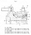
- a wheel bearing apparatus shown in Fig. 1 is for a driving wheel and is of the type called the third generation.
- the wheel bearing apparatus includes, as its main constituents, an inner member 10 corresponding to the bearing inner ring, an outer member 30 corresponding to the bearing outer ring, and two rows of rolling elements 28a, 28b.
- the inner member 10 and the outer member 30 are relatively rotatable via the rolling elements 28a, 28b.
- balls 28a, 28b are used as the rolling elements.
- the rows of balls 28a, 28b are retained at a predetermined interval in the circumferential direction by retainers 29a, 29b.
- the side closer to the center of the vehicle is referred to as an inboard side
- the side closer to the outside of the vehicle is referred to as an outboard side.
- the balls on the inboard side are denoted by reference character 28a with a suffix "a”
- the balls on the outboard side are denoted by reference character 28b with a suffix "b”.
- Such a denoting rule of reference characters holds true for raceway grooves 16a, 16b, 36a, 36b, the retainers 29a, 29b, and seals Sa, Sb.
- the inner member 10 is structured with a wheel hub 10A and an inner ring 10B. Two rows of raceway grooves 16a, 16b corresponding to inner ring raceways are respectively allocated to the inner ring 10B and the wheel hub 10A.
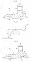
- the wheel hub 10A is formed by medium carbon steel containing carbon by 0.40 to 0.80 wt% such as S53C. As shown in Fig. 2 , the wheel hub 10A has a cylindrical portion 12 and a hub flange 14 which is positioned closer to the end portion on the outboard side (the left side in Figs. 1 and 2 ) of the cylindrical portion 12. In Fig. 2 , reference character hh represents the groove depth of the inboard side raceway groove 16b of the wheel hub 10A.
- the hub flange 14 is for attaching the wheel hub 10A to the wheel and a brake rotor.
- Hub bolts 15 are implanted into the hub flange 14 at a predetermined interval in the circumferential direction.
- Fig. 2 shows the wheel hub 10A before the hub bolts 15 are implanted into the hub flange 14. Screwing not-shown hub nuts with the hub bolts 15 fastens the wheel and the brake rotor and the hub flange 14 with each other.
- the wheel hub 10A is provided with a short cylindrical pilot portion at an end on the outboard side relative to the hub flange 14.
- the pilot portion is cylindrical with different diameters, in which the small diameter portion is a wheel pilot 20 and the great diameter portion is a disc pilot 22.
- the wheel pilot 20 and the disc pilot 22 serve to guide and center them, respectively.
- the inner diameter side of the pilot portion is hollowed to form a cylindrical inner circumferential surface 24.
- the cylindrical portion 12 of the wheel hub 10A has a serration (or spline, the same holds true for the following description) hole 26 that penetrates in the axial direction. Since the wheel bearing apparatus according to the embodiment is for a driving wheel, a serration shaft of an outer joint member of a not-shown constant velocity universal joint is inserted into the serration hole 26 of the wheel hub 10A so that the constant velocity universal joint and the wheel hub 10A are coupled to each other to be able to transmit torque. Since the structure of the constant velocity universal joint is well known and does not directly relate to the present invention, the detailed description thereof is not provided.
- the flange surface 13 rising from the disc pilot 22 on the outboard side in the radial direction serves as a disc attaching surface for attaching the brake rotor.
- a seal land 17 for allowing a seal lip of the seal Sb to be in contact with is provided at the root portion of the flange surface on the inboard side.
- the small diameter side of the seal land 17 extends in the axial direction and connected to the raceway groove 16b.
- a cylindrical small diameter shaft portion 18 is formed at the end of the cylindrical portion 12 on the inboard side (the right side in Figs. 1 and 2 ).
- the small diameter shaft portion 18 of the wheel hub 10A supports the inner ring 10B. That is, the inner ring 10B is interference-fitted to the small diameter shaft portion 18, having its end surface abutted on a shoulder surface 19 that rises from the small diameter shaft portion 18 in the radial direction. Therefore, the shoulder surface 19 is referred to as an inner ring abutting surface or simply as the abutting surface.
- the inner ring 10B is provided with the inboard-side raceway groove 16a on an outer circumference thereof.
- reference character hi represents the groove depth of the raceway groove 16a.
- a bevel 23 is formed at the edge of the raceway groove 16a by coining or the like, which bevel is not included in the groove depth hi. The same holds true for the inboard-side raceway groove 16b of the wheel hub 10A shown in Fig. 2 .
- Fig. 1 just simply shows the fixing scheme of the inner ring 10B.
- the preload can be managed by measuring torque during relative rotation of the inner member 10 and the outer member 30 and stop crimping when a torque value in a predetermined range is reached.
- the outer member 30 is made up of a sleeve 32 and a flange 34.
- the sleeve 32 is provided with two rows of outer ring raceways, that is, the raceway grooves 36a, 36b, on an inner circumference thereof.
- the raceway groove 36a is an inboard-side raceway groove and the raceway groove 36b is an outboard-side raceway groove. Since they are both outer ring raceways, as shown in Fig. 4A , the groove depth of each of the raceway grooves 36a, 36b is represented by reference character ho with a suffix "o".
- a bevel 37 is formed at the edge of each of raceway grooves 36a, 36b, which bevel 37 is not included in the groove depth ho.
- Fig. 4A shows an example where the inboard-side raceway groove 36a and the outboard-side raceway groove 36b have the identical groove depth ho
- Fig. 5 shows an example where they are different in the groove depth. That is, the groove depth of the inboard-side raceway groove 36a is represented by reference character ho-i, and the groove depth of the outboard-side raceway groove 36b by reference character ho-o. The outboard-side groove depth is greater than the inboard-side groove depth (ho-i ⁇ ho-o).
- raceway grooves 36a, 36b oppose to the raceway grooves 16a, 16b of the inner member 10 to form two rows of raceways for allowing the balls 28a, 28b to roll between the raceway grooves 36a, 36b and the raceway grooves 16a, 16b. In this manner, the inner member 10 and the outer member 30 are relatively rotatable via the balls 28a, 28b.
- the flange 34 of the outer member 30 is for fixing the outer member 30 to the knuckle of the vehicle body (the chassis), and is provided with a plurality of screw holes 35 for the fixing.
- a pilot outer diameter 38 is formed at the end of the outer member 30 on the inboard side for being inserted into the housing hole of the knuckle to center the outer member 30.
- the seals Sa, Sb are attached to the opposite openings of the outer member 30, so as to prevent leakage of lubricant such as grease with which the outer member 30 is filled inside, and entry of foreign matter from the outside.
- the seals Sa, Sb are attached to the opposite ends of the outer member 30.
- the inboard-side seal Sa is of the type referred to as a pack seal which is made up of an inner element and an outer element.
- the outer element is press fitted into a hole formed at the inboard-side end of the outer member 30, and the inner element is fitted to the outer diameter surface of the inner ring 10B.
- the outboard-side seal Sb has its mandrel portion press fitted into a hole formed at the outboard-side end of the outer member 30, and has its seal lip brought into contact with the seal land 17 of the wheel hub 10A.
- the inboard-side row of balls 28a and the outboard-side row of balls 28b are respectively in contact with the raceway grooves 16a, 16b of the inner member 10 and the raceway grooves 36a, 36b of the outer member 30 each at a contact angle.
- the contact angle is defined as an angle formed between a plane perpendicular to the bearing center axis (a radial plane) and a line of action of combined force transmitted from the raceway grooves 16a, 16b, 36a, 36b to the balls 28a, 28b (which is represented by alternate long and short dashed lines passing through the centers of the balls in Fig. 1 ).
- the embodiment corresponds to a back-to-back duplex arrangement, that is, two pieces of bearings being arranged so that the back sides of their respective outer rings are closely juxtaposed to each other. Since the present wheel bearing apparatus is capable of bearing the radial load and the axial loads in the opposite directions, it is suitable for the application in which a moment load acts, which may be observed when a vehicle makes a turn.
- the pilot outer diameter 38 of the outer member 30 is inserted into the housing hole of the knuckle, and the flange 34 is fixed to the knuckle by fastening bolts. Further, using the pilot portions (20, 22) of the inner member 10, the brake rotor (not shown) and the wheel (not shown) are attached to the hub bolts 15 of the hub flange 14, which hub bolts 15 are fastened by screwing hub nuts (not shown). At this time, the wheel is centered by the wheel pilot and the brake rotor is centered by the disc pilot.
- raceway grooves 16a, 16b of the inner member 10 and the raceway grooves 36a, 36b of the outer member 30 are the surfaces on which the balls 28a, 28b roll under a load
- a hardened layer is formed on each of the grooves by a surface hardening heat treatment.
- the hardness of the hardened layer is about HRC 50 to 65.
- An exemplary surface hardening heat treatment may be high frequency induction hardening or carburizing and quenching.
- High frequency induction hardening is a quenching method including: placing a portion necessary to be quenched inside a coil through which a high frequency current passes; and applying the principle of heating the electrically conductive material by Joule heat generated by the electromagnetic induction effect.
- Carburizing and quenching is a method including: heating steel for long hours in a gas, liquid, or solid carburizing agent that contains a great amount of activated carbon, thereby impregnating the surface layer of the steel with the carbon (a carburizing treatment); and subjecting the carburized steel to quenching and tempering.
- the raceway grooves 16a, 16b, 36a, 36b are finished by hardened steel cutting.
- Hardened steel cutting is cutting performed after quenching, and distinguished, by its being performed after a heat treatment (quenching), from normal cutting which is performed on a non-quenched workpiece. Performing cutting after quenching, heat treatment distortion of the material can be canceled out during the process. Further, quenching tends to leave tensile residual stress, which invites a reduction in fatigue strength when unaddressed.
- cutting the surface can provide compressive residual stress to the surface layer portion, improving the fatigue strength.
- a single-point cutting tool with which such cutting can be performed is used.
- An exemplary single-point cutting tool that can be used for hardened steel cutting may be a sintered compact tool in which a special ceramic binder is added to CBN (cubic boron nitride).
- CBN cubic boron nitride
- a chain double-dashed line represents an exemplary rhombus chip of a single-point cutting tool.
- the wheel hub 10A is finished to have the raceway groove 16b having a cross-sectional shape of a predetermined curvature, by being held by the cutting apparatus and rotated about its axis, and by adjustment of the cutting and axial feed of the single-point cutting tool.
- the inner ring 10B is subjected to a heat treatment as an independent inner ring before being fitted to the wheel hub 10A, and thereafter subjected to hardened steel cutting.
- the outer member 30 is finished to have the raceway grooves 36a, 36b each having a cross-sectional shape of a predetermined curvature, by being held by the cutting apparatus and rotated about its axis, and by adjustment of the cutting and axial feed of the single-point cutting tool.
- the outer member 30 is bored in contrast to the wheel hub 10A and inner ring 10B being cut around the outer diameter by hardened steel cutting.
- the two rows of raceway grooves 36a, 36b are subjected to hardened steel cutting with separate single-point cutting tools.
- finishing the raceway grooves 16a, 16b of the inner member 10 and the raceway grooves 36a, 36b of the outer member 30 by hardened steel cutting eliminates the necessity of performing grinding for finishing the raceway grooves 16a, 16b, 36a, 36b.
- raceway grooves 36a, 36b of the outer member 30 are finished by grinding
- a form grinding wheel having a portion corresponding to the two rows of raceway grooves 36a, 36b is used to cut the workpiece (outer member 30) at the right angle. Accordingly, it is geometrically impossible to form a raceway groove having a groove depth h which is 50% greater than a ball diameter d. Under present circumstances, 40% is the upper limit. Employing hardened steel cutting solves this challenge.
- the wheel bearing apparatus is for rotatably supporting a wheel, and includes: the inner member 10 having two rows of raceway grooves 16a, 16b along its outer circumference; the outer member 30 having two rows of raceway grooves 36a, 36b along its inner circumference; and a plurality of rolling elements 28a, 28b interposed between the raceway grooves 16a, 16b of the inner member 10 and the raceway grooves 36a, 36b of the outer member 30.
- the raceway grooves 16a, 16b of the inner member 10 and the raceway grooves 36a, 36b of the outer member 30 are formed by hardened steel cutting.
- h/d is set to exceed 0.50 where h is the depth of the raceway groove 16b and d is the diameter of the ball 28b.
- h/d is set to exceed 0.40 where h is the depth of the raceway grooves 36a, 36b and d is the diameter of the rolling elements 28a, 28b.
- hi/d is 0.63 or smaller where hi is the depth of the raceway grooves 16a, 16b of the inner member 10 and d is the diameter of the balls 28a, 28b.
- 0.63 d is still the limit of the groove depth h of the raceway grooves 16a, 16b of the inner member 10 from the limitations in the technical aspect.
- hh/d is 0.63 or smaller where hh is the depth of the raceway groove 16b of the wheel hub 10A.
- the upper limit of the groove depth h of the raceway grooves 36a, 36b of the outer member 30 is set to be 0.56 d.
- 0.56 d is still the limit of the groove depth h of the raceway grooves of the outer member from the limitations in the technical aspect.
- the groove depth of the outboard-side raceway groove 36b of the outer member 30 is greater than the groove depth of the inboard-side raceway groove 36a. Since a greater moment load acts on the outboard-side row of balls 28b than the inboard-side row of balls 28a, the outboard-side row of balls 28b tends to suffer from shoulder overriding. Accordingly, desirably a greatest possible groove depth is set.
- setting the groove depth of the outboard-side raceway groove to be greater than the groove depth of the inboard-side raceway groove improves resistance to indentation and prevents shoulder overriding of the contact ellipse, withstanding a great moment load put on the outboard-side ball row.
Landscapes
- Engineering & Computer Science (AREA)
- General Engineering & Computer Science (AREA)
- Mechanical Engineering (AREA)
- Manufacturing & Machinery (AREA)
- Rolling Contact Bearings (AREA)
Abstract
Description
- The present invention relates to a wheel bearing apparatus.
- A wheel bearing apparatus, which is also referred to as a hub bearing, is for supporting a wheel of an automobile. There are a bearing apparatus for a driving wheel and a bearing apparatus for a driven wheel.
- A wheel bearing apparatus has an inner member and an outer member which are relatively rotatable via rolling elements. One of the inner member and the outer member is fixed to a vehicle body, and the other is attached to a wheel. Accordingly, the member fixed to the vehicle body is the fixed side, and the member attached to the wheel is the rotating side. A wheel bearing apparatus having its inner member attached to the wheel and having its outer member attached to the vehicle body is referred to as an inner ring rotation type. A wheel bearing apparatus having its inner member fixed to the vehicle body and having its outer member attached to the wheel is referred to as an outer ring rotation type. In both of the types, the member attached to the wheel has a hub flange. Using hub bolts implanted into the hub flange and hub nuts, the wheel are fixed to the flange.
- The wheel bearing apparatus for a driving wheel is the inner ring rotation type because it must transmit power to the driving wheel. That is, the inner member having the hub flange for attaching the wheel is rotatably supported by the outer member fixed to a knuckle, and the inner member is coupled to a drive shaft.
- The wheel bearing apparatus for a driven wheel may be any of the inner ring rotation type and the outer ring rotation type. When it is the inner ring rotation type, the inner member is provided with the hub flange, and the inner member is rotatably supported by the outer member fixed to the vehicle body. When it is the outer ring rotation type, the outer member is provided with the hub flange, and the outer member is rotatably supported by the inner member fixed to the vehicle body.
- A double row angular contact ball bearing with low torque characteristics is popularly employed as the wheel bearing apparatus for its desirable bearing rigidity, durability withstanding misalignment, and improved fuel efficiency. In a double row angular contact ball bearing, balls in a plurality of rows are interposed between a bearing inner ring (inner race) and a bearing outer ring (outer race). The rings are in contact with the rows of balls at a predetermined contact angle. The inner member corresponding to the bearing inner ring has two rows of raceway grooves along its outer circumference, and the outer member corresponding to the bearing outer ring has two rows of raceway grooves along its inner circumference. Between the opposing paired raceway grooves, a plurality of balls roll. The rows of rolling elements are retained at a predetermined interval in the circumferential direction by retainers.
- In some cases, while the depth of a raceway groove, that is, the groove depth, is also referred to as a shoulder height, they are not exactly synonymous with each other. That is, the shoulder height is the distance from the bottom of a raceway groove to the upper surface of the shoulder (which is the outer diameter surface in relation to the inner member, and the inner diameter surface in relation to the outer member). On the other hand, the groove depth is the value obtained by subtracting, from the shoulder height, any chamfer, bevel, or auxiliary raceway surface provided at the surface of the raceway groove, that is, at the edge of the raceway surface. Accordingly, normally, the groove depth assumes a value smaller than the shoulder height. Here, the auxiliary raceway surface is a pseudo-raceway surface provided at the edge of the raceway surface so as to address an excessive load capacity. The cross-sectional shape of the raceway groove is an arc-shape. While the auxiliary raceway surface is continuous from the arc of the raceway groove, the auxiliary raceway surface is not formed by an extension of the arc of the identical curvature.
- Patent Literature 1 discloses, in paragraph 0006, an auxiliary raceway surface that smoothly continues from an arc-shaped curved line forming the cross section of a raceway groove. Provision of such an auxiliary raceway surface is expected to exhibit the following effects. That is, when a great moment load is put on the bearing and the contact angle increases, the contact ellipse is pushed out from the raceway groove to the auxiliary raceway surface. However, since the auxiliary raceway surface smoothly continues from the arc-shaped curved line that forms the raceway groove, generation of the edge load is not invited despite the contact ellipse being pushed out to the auxiliary raceway surface. Further, the inclination of the auxiliary raceway surface is greater than that of a surface being just an extension of the raceway surface. That is, since an inclination angle of certain degrees can be secured, the auxiliary raceway surface will not be ground with the side surface of a grinding wheel during grinding work. This avoids an increase in the grinding work hours.
- Patent Literature 2 discloses, in paragraphs 0005 to 0008, an auxiliary raceway surface that is provided at the edge of a raceway groove and smoothly continues from an arc-shaped curved line forming the raceway groove. The cross section of the auxiliary raceway surface is formed by a curved line with a curvature smaller than that of the arc-shaped curved line or by a straight line. While the effects exhibited by the auxiliary raceway surface are substantially similar to those of Patent Literature 1 as described above, in Patent Literature 2, a chamfered portion having an arc-shaped cross section being continuous to the edge of the auxiliary raceway surface is further formed. Thus, the edge load of the contact ellipse is further alleviated.
- Conventionally, from the aspects of functions and works, a ratio h/d of a groove depth h against a ball diameter d is h/d < 0.50 in relation to the inner ring and h/d < 0.40 in relation to the outer ring. With an h/d exceeding 0.50, in the cross section of the raceway groove, the sidewall of the raceway groove is inwardly warped, whereby grinding becomes difficult. Further, in relation to the outer ring, the upper limit of h/d is 0.40.
- The reason why the upper limit of the groove depth of the raceway groove is 0.40 d with the outer ring while the upper limit is 0.50 d with the inner ring is explained as follows. As to the inner ring, grinding work can be performed with an h/d exceeding 0.50, depending on the manner of abutting a grinding wheel. However, considering the number of work steps, it is practically difficult to achieve h/d > 0.50. As to the outer ring, double rows of raceway grooves are simultaneously ground for higher precision. The only solution for achieving the simultaneous high precision grinding is plunge grinding using a form grinding wheel whose contour matches with the cross-sectional shape of the raceway grooves and whose feed is the cutting direction. Accordingly, it is difficult to form deep grooves, and an h/d of 0.40 is the limit.
- Note that, H/d > 0.50 in relation to the inner ring can be achieved by provision of the above-described auxiliary raceway surface. Here, reference character H represents the shoulder height including the auxiliary raceway surface, and reference character h represents the groove depth not including the auxiliary raceway surface. That is, conventionally, while there do not exist bearings attaining h/d > 0.50, there exist bearings attaining H/d > 0.50 (see Patent Literature 2).
-
- Patent Literature 1:
Japanese Patent Laid-open Publication No. 2007-085555 - Patent Literature 2:
Japanese Patent Laid-open Publication No. 2011-241938 - During traveling of a vehicle, when a wheel bearing apparatus receives an excessive load from a wheel due to the vehicle making a turn or climbing up onto a curb, the contact ellipse between a ball and a raceway groove may override the shoulder, leaving indentations on the shoulder and emitting noises. In order to solve such an indentation problem, the shoulder height must be increased. On the other hand, an increase in the shoulder height invites an increase in the weight of the wheel bearing, a reduction in workability and the like, which disadvantageously results in an increase in costs. Further, an increase in the shoulder height of the inner ring reduces the cross-sectional height of a seal by the corresponding amount. Thus, sufficient sealability cannot be secured.
- Further, the raceway groove has a cross-sectional shape in which the contour gradually rises from the bottom toward the shoulder of the raceway groove. Accordingly, with a conventional grinding manner, the pressing force of the grinding wheel in the cutting direction does not fully act around the shoulder and the force that presses the grinding wheel against the workpiece becomes small. This disadvantageously results in long work hours or grinding burns. Further, the bearing provided with the auxiliary raceway surface cannot undergo superfinishing process. There is also a problem of how to check the shape of such a bearing.
- An object of the present invention is to provide a wheel bearing apparatus with which the problems described above are solved, and which is compact and capable of withstanding a high applied load without inviting an increase in the size of the bearing.
- According to the present invention, the object stated above is achieved by: employing hardened steel cutting as the method of forming the raceway grooves which is cutting performed after a heat treatment; providing the raceway grooves each having an arc-shaped raceway surface without an auxiliary raceway surface; and setting a great groove depth of h/D ≥ 0.50.
- That is, the present invention provides a wheel bearing apparatus for rotatably supporting a wheel, including: an inner member having two rows of raceway grooves on an outer circumference thereof; an outer member having two rows of raceway grooves on an inner circumference thereof; and a plurality of rolling elements interposed between the raceway grooves of the inner member and the raceway grooves of the outer member. The raceway grooves of the inner member and the raceway grooves of the outer member are formed by hardened steel cutting. In relation to at least a raceway groove on an outboard side out of the raceway grooves of the inner member, h/d exceeds 0.50 where h is a depth of the groove and d is a diameter of the rolling elements.
- According to the present invention, employing hardened steel cutting solves problems associated with grinding due to small pressing force in the cutting direction of a grinding wheel, that is, increased work hours and grinding burns, and enables work that provides a value higher than h/d ≥ 0.50. Accordingly, a high applied load which has been conventionally addressed by an increase in the size of the bearing is addressed by an increase in the shoulder height. Thus, a bearing without an increase in the size (of compact design) can be provided.
-
-
Fig. 1 is a half cross-sectional view of a wheel bearing apparatus for describing an embodiment. -
Fig. 2 is an enlarged view of a wheel hub inFig. 1 . -
Fig. 3A is an enlarged view of an inner ring inFig. 1 . -
Fig. 3B is an enlarged view of a raceway groove portion inFig. 3A . -
Fig. 4A is an enlarged view of an outer member inFig. 1 . -
Fig. 4B is an enlarged view of a raceway groove portion on an inboard side inFig. 4A . -
Fig. 5 is an enlarged view of an outer member similar to that shown inFig. 4A . - In the following, a description will be given of an embodiment of the present invention with reference to the attached drawings.
- A wheel bearing apparatus shown in
Fig. 1 is for a driving wheel and is of the type called the third generation. The wheel bearing apparatus includes, as its main constituents, aninner member 10 corresponding to the bearing inner ring, anouter member 30 corresponding to the bearing outer ring, and two rows of rollingelements inner member 10 and theouter member 30 are relatively rotatable via the rollingelements balls balls retainers - Here, in the state where the bearing is mounted on a vehicle, the side closer to the center of the vehicle is referred to as an inboard side, and the side closer to the outside of the vehicle is referred to as an outboard side. Of the two rows of balls, the balls on the inboard side are denoted by
reference character 28a with a suffix "a", and the balls on the outboard side are denoted byreference character 28b with a suffix "b". Such a denoting rule of reference characters holds true forraceway grooves retainers - The
inner member 10 is structured with awheel hub 10A and aninner ring 10B. Two rows ofraceway grooves inner ring 10B and thewheel hub 10A. - The
wheel hub 10A is formed by medium carbon steel containing carbon by 0.40 to 0.80 wt% such as S53C. As shown inFig. 2 , thewheel hub 10A has acylindrical portion 12 and ahub flange 14 which is positioned closer to the end portion on the outboard side (the left side inFigs. 1 and2 ) of thecylindrical portion 12. InFig. 2 , reference character hh represents the groove depth of the inboardside raceway groove 16b of thewheel hub 10A. - The
hub flange 14 is for attaching thewheel hub 10A to the wheel and a brake rotor.Hub bolts 15 are implanted into thehub flange 14 at a predetermined interval in the circumferential direction. Note that,Fig. 2 shows thewheel hub 10A before thehub bolts 15 are implanted into thehub flange 14. Screwing not-shown hub nuts with thehub bolts 15 fastens the wheel and the brake rotor and thehub flange 14 with each other. - The
wheel hub 10A is provided with a short cylindrical pilot portion at an end on the outboard side relative to thehub flange 14. The pilot portion is cylindrical with different diameters, in which the small diameter portion is awheel pilot 20 and the great diameter portion is adisc pilot 22. In attaching the wheel and the brake rotor, thewheel pilot 20 and thedisc pilot 22 serve to guide and center them, respectively. The inner diameter side of the pilot portion is hollowed to form a cylindrical innercircumferential surface 24. - The
cylindrical portion 12 of thewheel hub 10A has a serration (or spline, the same holds true for the following description)hole 26 that penetrates in the axial direction. Since the wheel bearing apparatus according to the embodiment is for a driving wheel, a serration shaft of an outer joint member of a not-shown constant velocity universal joint is inserted into theserration hole 26 of thewheel hub 10A so that the constant velocity universal joint and thewheel hub 10A are coupled to each other to be able to transmit torque. Since the structure of the constant velocity universal joint is well known and does not directly relate to the present invention, the detailed description thereof is not provided. - In the flange surface of the
hub flange 14, theflange surface 13 rising from thedisc pilot 22 on the outboard side in the radial direction serves as a disc attaching surface for attaching the brake rotor. At the root portion of the flange surface on the inboard side, aseal land 17 for allowing a seal lip of the seal Sb to be in contact with is provided. The small diameter side of theseal land 17 extends in the axial direction and connected to theraceway groove 16b. At the end of thecylindrical portion 12 on the inboard side (the right side inFigs. 1 and2 ), a cylindrical smalldiameter shaft portion 18 is formed. - The small
diameter shaft portion 18 of thewheel hub 10A supports theinner ring 10B. That is, theinner ring 10B is interference-fitted to the smalldiameter shaft portion 18, having its end surface abutted on ashoulder surface 19 that rises from the smalldiameter shaft portion 18 in the radial direction. Therefore, theshoulder surface 19 is referred to as an inner ring abutting surface or simply as the abutting surface. - The
inner ring 10B is provided with the inboard-side raceway groove 16a on an outer circumference thereof. InFigs. 3A and 3B , reference character hi represents the groove depth of theraceway groove 16a. As can be seen fromFig. 3B , abevel 23 is formed at the edge of theraceway groove 16a by coining or the like, which bevel is not included in the groove depth hi. The same holds true for the inboard-side raceway groove 16b of thewheel hub 10A shown inFig. 2 . -
Fig. 1 just simply shows the fixing scheme of theinner ring 10B. For example, in the state where theinner ring 10B abuts on the abuttingsurface 19, crimping the end of the smalldiameter shaft portion 18 of thewheel hub 10A can fix theinner ring 10B onto the smalldiameter shaft portion 18. Here, for example, by theinner ring 10B being axially applied with pressure toward the abuttingsurface 19, the distance between theraceway grooves inner member 10 and theouter member 30 and stop crimping when a torque value in a predetermined range is reached. - The
outer member 30 is made up of asleeve 32 and aflange 34. Thesleeve 32 is provided with two rows of outer ring raceways, that is, theraceway grooves raceway groove 36a is an inboard-side raceway groove and theraceway groove 36b is an outboard-side raceway groove. Since they are both outer ring raceways, as shown inFig. 4A , the groove depth of each of theraceway grooves Fig. 4B , abevel 37 is formed at the edge of each ofraceway grooves - Further, while
Fig. 4A shows an example where the inboard-side raceway groove 36a and the outboard-side raceway groove 36b have the identical groove depth ho,Fig. 5 shows an example where they are different in the groove depth. That is, the groove depth of the inboard-side raceway groove 36a is represented by reference character ho-i, and the groove depth of the outboard-side raceway groove 36b by reference character ho-o. The outboard-side groove depth is greater than the inboard-side groove depth (ho-i < ho-o). - These
raceway grooves raceway grooves inner member 10 to form two rows of raceways for allowing theballs raceway grooves raceway grooves inner member 10 and theouter member 30 are relatively rotatable via theballs - The
flange 34 of theouter member 30 is for fixing theouter member 30 to the knuckle of the vehicle body (the chassis), and is provided with a plurality of screw holes 35 for the fixing. A pilotouter diameter 38 is formed at the end of theouter member 30 on the inboard side for being inserted into the housing hole of the knuckle to center theouter member 30. - The seals Sa, Sb are attached to the opposite openings of the
outer member 30, so as to prevent leakage of lubricant such as grease with which theouter member 30 is filled inside, and entry of foreign matter from the outside. The seals Sa, Sb are attached to the opposite ends of theouter member 30. Specifically, the inboard-side seal Sa is of the type referred to as a pack seal which is made up of an inner element and an outer element. The outer element is press fitted into a hole formed at the inboard-side end of theouter member 30, and the inner element is fitted to the outer diameter surface of theinner ring 10B. The outboard-side seal Sb has its mandrel portion press fitted into a hole formed at the outboard-side end of theouter member 30, and has its seal lip brought into contact with theseal land 17 of thewheel hub 10A. - The inboard-side row of
balls 28a and the outboard-side row ofballs 28b are respectively in contact with theraceway grooves inner member 10 and theraceway grooves outer member 30 each at a contact angle. The contact angle is defined as an angle formed between a plane perpendicular to the bearing center axis (a radial plane) and a line of action of combined force transmitted from theraceway grooves balls Fig. 1 ). The embodiment corresponds to a back-to-back duplex arrangement, that is, two pieces of bearings being arranged so that the back sides of their respective outer rings are closely juxtaposed to each other. Since the present wheel bearing apparatus is capable of bearing the radial load and the axial loads in the opposite directions, it is suitable for the application in which a moment load acts, which may be observed when a vehicle makes a turn. - In mounting the wheel bearing apparatus structured as described above on an actual vehicle, the pilot
outer diameter 38 of theouter member 30 is inserted into the housing hole of the knuckle, and theflange 34 is fixed to the knuckle by fastening bolts. Further, using the pilot portions (20, 22) of theinner member 10, the brake rotor (not shown) and the wheel (not shown) are attached to thehub bolts 15 of thehub flange 14, whichhub bolts 15 are fastened by screwing hub nuts (not shown). At this time, the wheel is centered by the wheel pilot and the brake rotor is centered by the disc pilot. - Meanwhile, since the
raceway grooves inner member 10 and theraceway grooves outer member 30 are the surfaces on which theballs - An exemplary surface hardening heat treatment may be high frequency induction hardening or carburizing and quenching. High frequency induction hardening is a quenching method including: placing a portion necessary to be quenched inside a coil through which a high frequency current passes; and applying the principle of heating the electrically conductive material by Joule heat generated by the electromagnetic induction effect. Carburizing and quenching is a method including: heating steel for long hours in a gas, liquid, or solid carburizing agent that contains a great amount of activated carbon, thereby impregnating the surface layer of the steel with the carbon (a carburizing treatment); and subjecting the carburized steel to quenching and tempering.
- The
raceway grooves - As a cutting tool, a single-point cutting tool with which such cutting can be performed is used. An exemplary single-point cutting tool that can be used for hardened steel cutting may be a sintered compact tool in which a special ceramic binder is added to CBN (cubic boron nitride). In
Figs. 3B and4B , a chain double-dashed line represents an exemplary rhombus chip of a single-point cutting tool. - The
wheel hub 10A is finished to have theraceway groove 16b having a cross-sectional shape of a predetermined curvature, by being held by the cutting apparatus and rotated about its axis, and by adjustment of the cutting and axial feed of the single-point cutting tool. This substantially holds true for theinner ring 10B at least as to hardened steel cutting of theraceway groove 16a. Note that, theinner ring 10B is subjected to a heat treatment as an independent inner ring before being fitted to thewheel hub 10A, and thereafter subjected to hardened steel cutting. - The
outer member 30 is finished to have theraceway grooves outer member 30 is bored in contrast to thewheel hub 10A andinner ring 10B being cut around the outer diameter by hardened steel cutting. Further, the two rows ofraceway grooves - In this manner, finishing the
raceway grooves inner member 10 and theraceway grooves outer member 30 by hardened steel cutting eliminates the necessity of performing grinding for finishing theraceway grooves - In the case where the
raceway grooves outer member 30 are finished by grinding, a form grinding wheel having a portion corresponding to the two rows ofraceway grooves - The effect of the embodiment described above is summarized and listed below.
- The wheel bearing apparatus according to the embodiment is for rotatably supporting a wheel, and includes: the
inner member 10 having two rows ofraceway grooves outer member 30 having two rows ofraceway grooves elements raceway grooves inner member 10 and theraceway grooves outer member 30. Theraceway grooves inner member 10 and theraceway grooves outer member 30 are formed by hardened steel cutting. In relation to at least theraceway groove 16b on the outboard side out of theraceway grooves inner member 10, h/d is set to exceed 0.50 where h is the depth of theraceway groove 16b and d is the diameter of theball 28b. - In relation to the
raceway grooves outer member 30, h/d is set to exceed 0.40 where h is the depth of theraceway grooves elements - Preferably, hi/d is 0.63 or smaller where hi is the depth of the
raceway grooves inner member 10 and d is the diameter of theballs raceway grooves inner member 10 from the limitations in the technical aspect. - Preferably, hh/d is 0.63 or smaller where hh is the depth of the
raceway groove 16b of thewheel hub 10A. - Preferably, the upper limit of the groove depth h of the
raceway grooves outer member 30 is set to be 0.56 d. Using hardened steel cutting, 0.56 d is still the limit of the groove depth h of the raceway grooves of the outer member from the limitations in the technical aspect. - Preferably, the groove depth of the outboard-
side raceway groove 36b of theouter member 30 is greater than the groove depth of the inboard-side raceway groove 36a. Since a greater moment load acts on the outboard-side row ofballs 28b than the inboard-side row ofballs 28a, the outboard-side row ofballs 28b tends to suffer from shoulder overriding. Accordingly, desirably a greatest possible groove depth is set. Here, setting the groove depth of the outboard-side raceway groove to be greater than the groove depth of the inboard-side raceway groove improves resistance to indentation and prevents shoulder overriding of the contact ellipse, withstanding a great moment load put on the outboard-side ball row. This prevents generation of edge loads, and improves the noise level and the life of the bearing. Further, setting a minimum possible groove depth of the tolerating inboard-side raceway groove 36a thereby reducing the work hours, a reduction in the whole work hours can be achieved. - In the foregoing, the embodiment of the present invention has been described with reference to the attached drawings. It goes without saying that the present invention is not limited to the described and illustrated embodiment, and can be carried out with various modifications without departing from the scope of claims.
-
- 10:
- Inner member
- 10A:
- Wheel hub
- 10B:
- Inner ring
- 12:
- Cylindrical portion
- 14:
- Hub flange
- 16a:
- Raceway groove (inboard side)
- 16b:
- Raceway groove (outboard side)
- 17:
- Seal land
- 18:
- Small diameter shaft portion
- 20:
- Wheel pilot
- 22:
- Disc pilot
- 23:
- Bevel
- 26:
- Serration hole
- 28a:
- Ball (inboard side)
- 28b:
- Ball (outboard side)
- 29a:
- Retainer (inboard side)
- 29b:
- Retainer (outboard side)
- 30:
- Outer member
- 32:
- Sleeve
- 34:
- Flange
- 36a:
- Raceway groove (inboard side)
- 36b:
- Raceway groove (outboard side)
- 37:
- Bevel
- 38:
- Pilot outer diameter
- Sa:
- Seal (inboard side)
- Sb:
- Seal (outboard side)
Claims (6)
- A wheel bearing apparatus for rotatably supporting a wheel, comprising:an inner member having two rows of raceway grooves on an outer circumference thereof;an outer member having two rows of raceway grooves on an inner circumference thereof; anda plurality of rolling elements interposed between the raceway grooves of the inner member and the raceway grooves of the outer member, whereinthe raceway grooves of the inner member and the raceway grooves of the outer member are formed by hardened steel cutting after a heat treatment, andin relation to at least a raceway groove on an outboard side out of the raceway grooves of the inner member, h/d exceeds 0.50 where h is a depth of the groove and d is a diameter of the rolling elements.
- The wheel bearing apparatus according to claim 1, wherein, in relation to the raceway grooves of the outer member, h/d exceeds 0.40.
- The wheel bearing apparatus according to one of claims 1 and 2, wherein hi/d is 0.63 or smaller where hi is a depth of the raceway grooves of the inner member and d is the diameter of the balls.
- The wheel bearing apparatus according to one of claims 1, 2 and 3 wherein hh/d is 0.63 or smaller where hh is a depth of the raceway groove of the wheel hub.
- The wheel bearing apparatus according to one of claims 1 to 4, wherein, in relation to the raceway grooves of the outer member, h/d is 0.56 or smaller.
- The wheel bearing apparatus according to claim 1, wherein, among the raceway grooves of the outer member, a raceway groove on an outboard side is greater in depth than a raceway groove on an inboard side.
Applications Claiming Priority (2)
| Application Number | Priority Date | Filing Date | Title |
|---|---|---|---|
| JP2014108109A JP6422669B2 (en) | 2014-05-26 | 2014-05-26 | Wheel bearing device |
| PCT/JP2015/063436 WO2015182357A1 (en) | 2014-05-26 | 2015-05-11 | Wheel bearing device |
Publications (3)
| Publication Number | Publication Date |
|---|---|
| EP3150873A1 true EP3150873A1 (en) | 2017-04-05 |
| EP3150873A4 EP3150873A4 (en) | 2018-03-07 |
| EP3150873B1 EP3150873B1 (en) | 2020-06-24 |
Family
ID=54698697
Family Applications (1)
| Application Number | Title | Priority Date | Filing Date |
|---|---|---|---|
| EP15799506.9A Not-in-force EP3150873B1 (en) | 2014-05-26 | 2015-05-11 | Wheel bearing device |
Country Status (5)
| Country | Link |
|---|---|
| US (1) | US10087988B2 (en) |
| EP (1) | EP3150873B1 (en) |
| JP (1) | JP6422669B2 (en) |
| CN (1) | CN106415037B (en) |
| WO (1) | WO2015182357A1 (en) |
Cited By (2)
| Publication number | Priority date | Publication date | Assignee | Title |
|---|---|---|---|---|
| EP3403848A1 (en) * | 2017-04-18 | 2018-11-21 | Toyota Jidosha Kabushiki Kaisha | Wheel mounting structure |
| IT202200007313A1 (en) * | 2022-04-13 | 2023-10-13 | Skf Ab | BEARING-HUB ASSEMBLY FOR A MOTOR VEHICLE WHEEL |
Families Citing this family (4)
| Publication number | Priority date | Publication date | Assignee | Title |
|---|---|---|---|---|
| JP2019019870A (en) * | 2017-07-14 | 2019-02-07 | 株式会社ジェイテクト | Wheel bearing device and sealing device |
| DE102019205782B4 (en) * | 2019-04-23 | 2022-04-28 | Audi Ag | Wheel bearing arrangement for a motor vehicle |
| JP7367379B2 (en) * | 2019-08-20 | 2023-10-24 | 日本精工株式会社 | Manufacturing method of inner ring for hub unit bearing |
| US12152636B2 (en) | 2020-05-22 | 2024-11-26 | Nok Corporation | Sealing device |
Family Cites Families (15)
| Publication number | Priority date | Publication date | Assignee | Title |
|---|---|---|---|---|
| JP3690821B2 (en) * | 1993-12-15 | 2005-08-31 | 日本精工株式会社 | Double row angular contact ball bearings for wheels |
| JP4455182B2 (en) * | 2004-06-24 | 2010-04-21 | Ntn株式会社 | Wheel bearing device |
| JP2007071628A (en) * | 2005-09-06 | 2007-03-22 | Ntn Corp | Wheel bearing with sensor |
| JP4489672B2 (en) * | 2005-09-20 | 2010-06-23 | Ntn株式会社 | Wheel bearing device |
| WO2007037477A1 (en) * | 2005-09-30 | 2007-04-05 | Ntn Corporation | Bearing device for wheel |
| JP4251332B2 (en) | 2006-12-21 | 2009-04-08 | Ntn株式会社 | Wheel bearing device |
| JP5184875B2 (en) * | 2007-12-19 | 2013-04-17 | Ntn株式会社 | Wheel bearing device |
| JP2009191909A (en) * | 2008-02-13 | 2009-08-27 | Ntn Corp | Wheel bearing device |
| DE112009003533B4 (en) | 2008-12-09 | 2019-05-23 | Ntn Corporation | Wheel bearing device for a vehicle |
| JP2011002030A (en) * | 2009-06-18 | 2011-01-06 | Ntn Corp | Wheel bearing |
| JP5570297B2 (en) | 2010-05-20 | 2014-08-13 | Ntn株式会社 | Wheel bearing device |
| JP5852388B2 (en) * | 2011-09-29 | 2016-02-03 | Ntn株式会社 | Wheel bearing device |
| WO2013035756A1 (en) * | 2011-09-06 | 2013-03-14 | Ntn株式会社 | Bearing device for wheel |
| DE102012216598B4 (en) * | 2012-09-18 | 2022-08-25 | Schaeffler Technologies AG & Co. KG | Wheel bearing arrangement for a vehicle |
| JP6114556B2 (en) * | 2013-01-09 | 2017-04-12 | Ntn株式会社 | Wheel bearing device |
-
2014
- 2014-05-26 JP JP2014108109A patent/JP6422669B2/en not_active Expired - Fee Related
-
2015
- 2015-05-11 CN CN201580026108.0A patent/CN106415037B/en not_active Expired - Fee Related
- 2015-05-11 US US15/312,390 patent/US10087988B2/en not_active Expired - Fee Related
- 2015-05-11 WO PCT/JP2015/063436 patent/WO2015182357A1/en not_active Ceased
- 2015-05-11 EP EP15799506.9A patent/EP3150873B1/en not_active Not-in-force
Cited By (4)
| Publication number | Priority date | Publication date | Assignee | Title |
|---|---|---|---|---|
| EP3403848A1 (en) * | 2017-04-18 | 2018-11-21 | Toyota Jidosha Kabushiki Kaisha | Wheel mounting structure |
| IT202200007313A1 (en) * | 2022-04-13 | 2023-10-13 | Skf Ab | BEARING-HUB ASSEMBLY FOR A MOTOR VEHICLE WHEEL |
| CN116901616A (en) * | 2022-04-13 | 2023-10-20 | 斯凯孚公司 | Hub bearing unit for a wheel of a motor vehicle |
| US12304238B2 (en) | 2022-04-13 | 2025-05-20 | Aktiebolaget Skf | Hub-bearing unit for a wheel of a motor vehicle |
Also Published As
| Publication number | Publication date |
|---|---|
| WO2015182357A1 (en) | 2015-12-03 |
| JP6422669B2 (en) | 2018-11-14 |
| JP2015224655A (en) | 2015-12-14 |
| EP3150873B1 (en) | 2020-06-24 |
| CN106415037A (en) | 2017-02-15 |
| EP3150873A4 (en) | 2018-03-07 |
| CN106415037B (en) | 2019-03-15 |
| US20170097045A1 (en) | 2017-04-06 |
| US10087988B2 (en) | 2018-10-02 |
Similar Documents
| Publication | Publication Date | Title |
|---|---|---|
| EP3150873B1 (en) | Wheel bearing device | |
| US10207536B2 (en) | Drive wheel bearing and method of manufacturing the same | |
| CN100436853C (en) | Wheel bearing device and manufacturing method thereof | |
| EP2573412B1 (en) | Vehicle wheel bearing device | |
| JP2008174208A (en) | Hub ring of bearing device for wheel and method of producing the same | |
| US20120148181A1 (en) | Wheel Bearing | |
| US8092096B2 (en) | Wheel bearing apparatus for a vehicle | |
| US20060033381A1 (en) | Bearing apparatus for a wheel of vehicle | |
| KR102543652B1 (en) | wheel bearing assembly | |
| JP2013053707A (en) | Wheel bearing device | |
| JP6366233B2 (en) | Wheel bearing device | |
| JP2012180091A (en) | Bearing device for wheel | |
| JP2005096617A (en) | Bearing device for wheel | |
| JP2009191902A (en) | Wheel bearing device | |
| EP1726388B1 (en) | Method of manufacturing bearing device for vehicle | |
| KR20170013666A (en) | Tandem angular contact ball bearing, axle for vehicle applying the same and method of measuring bearing axial inside clearance thereof | |
| JP2025067505A (en) | Method for manufacturing outer ring of hub unit bearing | |
| JP2012189217A (en) | Wheel bearing device | |
| JP2013151223A (en) | Bearing device for driving wheel | |
| EP2113394A1 (en) | Bearing for wheel and method for manufacturing the same | |
| KR102543235B1 (en) | Wheel bearing assembly | |
| JP2013076424A (en) | Bearing device for wheel | |
| KR102556455B1 (en) | Wheel bearing assembly | |
| JP2009191907A (en) | Wheel bearing device | |
| JP2004338584A (en) | Manufacturing method of bearing unit for driving wheel and drive unit for wheel |
Legal Events
| Date | Code | Title | Description |
|---|---|---|---|
| STAA | Information on the status of an ep patent application or granted ep patent |
Free format text: STATUS: THE INTERNATIONAL PUBLICATION HAS BEEN MADE |
|
| PUAI | Public reference made under article 153(3) epc to a published international application that has entered the european phase |
Free format text: ORIGINAL CODE: 0009012 |
|
| STAA | Information on the status of an ep patent application or granted ep patent |
Free format text: STATUS: REQUEST FOR EXAMINATION WAS MADE |
|
| 17P | Request for examination filed |
Effective date: 20161220 |
|
| AK | Designated contracting states |
Kind code of ref document: A1 Designated state(s): AL AT BE BG CH CY CZ DE DK EE ES FI FR GB GR HR HU IE IS IT LI LT LU LV MC MK MT NL NO PL PT RO RS SE SI SK SM TR |
|
| AX | Request for extension of the european patent |
Extension state: BA ME |
|
| DAV | Request for validation of the european patent (deleted) | ||
| DAX | Request for extension of the european patent (deleted) | ||
| A4 | Supplementary search report drawn up and despatched |
Effective date: 20180202 |
|
| RIC1 | Information provided on ipc code assigned before grant |
Ipc: B60B 35/14 20060101ALI20180129BHEP Ipc: F16C 33/64 20060101AFI20180129BHEP Ipc: B60B 35/18 20060101ALI20180129BHEP Ipc: F16C 33/58 20060101ALI20180129BHEP Ipc: F16C 19/18 20060101ALI20180129BHEP |
|
| STAA | Information on the status of an ep patent application or granted ep patent |
Free format text: STATUS: EXAMINATION IS IN PROGRESS |
|
| 17Q | First examination report despatched |
Effective date: 20190404 |
|
| GRAP | Despatch of communication of intention to grant a patent |
Free format text: ORIGINAL CODE: EPIDOSNIGR1 |
|
| STAA | Information on the status of an ep patent application or granted ep patent |
Free format text: STATUS: GRANT OF PATENT IS INTENDED |
|
| INTG | Intention to grant announced |
Effective date: 20200217 |
|
| GRAS | Grant fee paid |
Free format text: ORIGINAL CODE: EPIDOSNIGR3 |
|
| GRAA | (expected) grant |
Free format text: ORIGINAL CODE: 0009210 |
|
| STAA | Information on the status of an ep patent application or granted ep patent |
Free format text: STATUS: THE PATENT HAS BEEN GRANTED |
|
| AK | Designated contracting states |
Kind code of ref document: B1 Designated state(s): AL AT BE BG CH CY CZ DE DK EE ES FI FR GB GR HR HU IE IS IT LI LT LU LV MC MK MT NL NO PL PT RO RS SE SI SK SM TR |
|
| REG | Reference to a national code |
Ref country code: GB Ref legal event code: FG4D |
|
| REG | Reference to a national code |
Ref country code: CH Ref legal event code: EP |
|
| REG | Reference to a national code |
Ref country code: AT Ref legal event code: REF Ref document number: 1284182 Country of ref document: AT Kind code of ref document: T Effective date: 20200715 |
|
| REG | Reference to a national code |
Ref country code: DE Ref legal event code: R096 Ref document number: 602015054799 Country of ref document: DE |
|
| REG | Reference to a national code |
Ref country code: IE Ref legal event code: FG4D |
|
| PG25 | Lapsed in a contracting state [announced via postgrant information from national office to epo] |
Ref country code: LT Free format text: LAPSE BECAUSE OF FAILURE TO SUBMIT A TRANSLATION OF THE DESCRIPTION OR TO PAY THE FEE WITHIN THE PRESCRIBED TIME-LIMIT Effective date: 20200624 Ref country code: NO Free format text: LAPSE BECAUSE OF FAILURE TO SUBMIT A TRANSLATION OF THE DESCRIPTION OR TO PAY THE FEE WITHIN THE PRESCRIBED TIME-LIMIT Effective date: 20200924 Ref country code: SE Free format text: LAPSE BECAUSE OF FAILURE TO SUBMIT A TRANSLATION OF THE DESCRIPTION OR TO PAY THE FEE WITHIN THE PRESCRIBED TIME-LIMIT Effective date: 20200624 Ref country code: FI Free format text: LAPSE BECAUSE OF FAILURE TO SUBMIT A TRANSLATION OF THE DESCRIPTION OR TO PAY THE FEE WITHIN THE PRESCRIBED TIME-LIMIT Effective date: 20200624 Ref country code: GR Free format text: LAPSE BECAUSE OF FAILURE TO SUBMIT A TRANSLATION OF THE DESCRIPTION OR TO PAY THE FEE WITHIN THE PRESCRIBED TIME-LIMIT Effective date: 20200925 |
|
| REG | Reference to a national code |
Ref country code: LT Ref legal event code: MG4D |
|
| PG25 | Lapsed in a contracting state [announced via postgrant information from national office to epo] |
Ref country code: HR Free format text: LAPSE BECAUSE OF FAILURE TO SUBMIT A TRANSLATION OF THE DESCRIPTION OR TO PAY THE FEE WITHIN THE PRESCRIBED TIME-LIMIT Effective date: 20200624 Ref country code: RS Free format text: LAPSE BECAUSE OF FAILURE TO SUBMIT A TRANSLATION OF THE DESCRIPTION OR TO PAY THE FEE WITHIN THE PRESCRIBED TIME-LIMIT Effective date: 20200624 Ref country code: LV Free format text: LAPSE BECAUSE OF FAILURE TO SUBMIT A TRANSLATION OF THE DESCRIPTION OR TO PAY THE FEE WITHIN THE PRESCRIBED TIME-LIMIT Effective date: 20200624 Ref country code: BG Free format text: LAPSE BECAUSE OF FAILURE TO SUBMIT A TRANSLATION OF THE DESCRIPTION OR TO PAY THE FEE WITHIN THE PRESCRIBED TIME-LIMIT Effective date: 20200924 |
|
| REG | Reference to a national code |
Ref country code: NL Ref legal event code: MP Effective date: 20200624 |
|
| REG | Reference to a national code |
Ref country code: AT Ref legal event code: MK05 Ref document number: 1284182 Country of ref document: AT Kind code of ref document: T Effective date: 20200624 |
|
| PG25 | Lapsed in a contracting state [announced via postgrant information from national office to epo] |
Ref country code: NL Free format text: LAPSE BECAUSE OF FAILURE TO SUBMIT A TRANSLATION OF THE DESCRIPTION OR TO PAY THE FEE WITHIN THE PRESCRIBED TIME-LIMIT Effective date: 20200624 Ref country code: AL Free format text: LAPSE BECAUSE OF FAILURE TO SUBMIT A TRANSLATION OF THE DESCRIPTION OR TO PAY THE FEE WITHIN THE PRESCRIBED TIME-LIMIT Effective date: 20200624 |
|
| PG25 | Lapsed in a contracting state [announced via postgrant information from national office to epo] |
Ref country code: RO Free format text: LAPSE BECAUSE OF FAILURE TO SUBMIT A TRANSLATION OF THE DESCRIPTION OR TO PAY THE FEE WITHIN THE PRESCRIBED TIME-LIMIT Effective date: 20200624 Ref country code: CZ Free format text: LAPSE BECAUSE OF FAILURE TO SUBMIT A TRANSLATION OF THE DESCRIPTION OR TO PAY THE FEE WITHIN THE PRESCRIBED TIME-LIMIT Effective date: 20200624 Ref country code: AT Free format text: LAPSE BECAUSE OF FAILURE TO SUBMIT A TRANSLATION OF THE DESCRIPTION OR TO PAY THE FEE WITHIN THE PRESCRIBED TIME-LIMIT Effective date: 20200624 Ref country code: SM Free format text: LAPSE BECAUSE OF FAILURE TO SUBMIT A TRANSLATION OF THE DESCRIPTION OR TO PAY THE FEE WITHIN THE PRESCRIBED TIME-LIMIT Effective date: 20200624 Ref country code: IT Free format text: LAPSE BECAUSE OF FAILURE TO SUBMIT A TRANSLATION OF THE DESCRIPTION OR TO PAY THE FEE WITHIN THE PRESCRIBED TIME-LIMIT Effective date: 20200624 Ref country code: EE Free format text: LAPSE BECAUSE OF FAILURE TO SUBMIT A TRANSLATION OF THE DESCRIPTION OR TO PAY THE FEE WITHIN THE PRESCRIBED TIME-LIMIT Effective date: 20200624 Ref country code: ES Free format text: LAPSE BECAUSE OF FAILURE TO SUBMIT A TRANSLATION OF THE DESCRIPTION OR TO PAY THE FEE WITHIN THE PRESCRIBED TIME-LIMIT Effective date: 20200624 Ref country code: PT Free format text: LAPSE BECAUSE OF FAILURE TO SUBMIT A TRANSLATION OF THE DESCRIPTION OR TO PAY THE FEE WITHIN THE PRESCRIBED TIME-LIMIT Effective date: 20201026 |
|
| PG25 | Lapsed in a contracting state [announced via postgrant information from national office to epo] |
Ref country code: SK Free format text: LAPSE BECAUSE OF FAILURE TO SUBMIT A TRANSLATION OF THE DESCRIPTION OR TO PAY THE FEE WITHIN THE PRESCRIBED TIME-LIMIT Effective date: 20200624 Ref country code: PL Free format text: LAPSE BECAUSE OF FAILURE TO SUBMIT A TRANSLATION OF THE DESCRIPTION OR TO PAY THE FEE WITHIN THE PRESCRIBED TIME-LIMIT Effective date: 20200624 Ref country code: IS Free format text: LAPSE BECAUSE OF FAILURE TO SUBMIT A TRANSLATION OF THE DESCRIPTION OR TO PAY THE FEE WITHIN THE PRESCRIBED TIME-LIMIT Effective date: 20201024 |
|
| REG | Reference to a national code |
Ref country code: DE Ref legal event code: R097 Ref document number: 602015054799 Country of ref document: DE |
|
| PG25 | Lapsed in a contracting state [announced via postgrant information from national office to epo] |
Ref country code: DK Free format text: LAPSE BECAUSE OF FAILURE TO SUBMIT A TRANSLATION OF THE DESCRIPTION OR TO PAY THE FEE WITHIN THE PRESCRIBED TIME-LIMIT Effective date: 20200624 |
|
| PLBE | No opposition filed within time limit |
Free format text: ORIGINAL CODE: 0009261 |
|
| STAA | Information on the status of an ep patent application or granted ep patent |
Free format text: STATUS: NO OPPOSITION FILED WITHIN TIME LIMIT |
|
| 26N | No opposition filed |
Effective date: 20210325 |
|
| PGFP | Annual fee paid to national office [announced via postgrant information from national office to epo] |
Ref country code: DE Payment date: 20210520 Year of fee payment: 7 Ref country code: FR Payment date: 20210522 Year of fee payment: 7 |
|
| PG25 | Lapsed in a contracting state [announced via postgrant information from national office to epo] |
Ref country code: SI Free format text: LAPSE BECAUSE OF FAILURE TO SUBMIT A TRANSLATION OF THE DESCRIPTION OR TO PAY THE FEE WITHIN THE PRESCRIBED TIME-LIMIT Effective date: 20200624 |
|
| REG | Reference to a national code |
Ref country code: CH Ref legal event code: PL |
|
| GBPC | Gb: european patent ceased through non-payment of renewal fee |
Effective date: 20210511 |
|
| PG25 | Lapsed in a contracting state [announced via postgrant information from national office to epo] |
Ref country code: LU Free format text: LAPSE BECAUSE OF NON-PAYMENT OF DUE FEES Effective date: 20210511 Ref country code: MC Free format text: LAPSE BECAUSE OF FAILURE TO SUBMIT A TRANSLATION OF THE DESCRIPTION OR TO PAY THE FEE WITHIN THE PRESCRIBED TIME-LIMIT Effective date: 20200624 Ref country code: LI Free format text: LAPSE BECAUSE OF NON-PAYMENT OF DUE FEES Effective date: 20210531 Ref country code: CH Free format text: LAPSE BECAUSE OF NON-PAYMENT OF DUE FEES Effective date: 20210531 |
|
| REG | Reference to a national code |
Ref country code: BE Ref legal event code: MM Effective date: 20210531 |
|
| PG25 | Lapsed in a contracting state [announced via postgrant information from national office to epo] |
Ref country code: IE Free format text: LAPSE BECAUSE OF NON-PAYMENT OF DUE FEES Effective date: 20210511 Ref country code: GB Free format text: LAPSE BECAUSE OF NON-PAYMENT OF DUE FEES Effective date: 20210511 |
|
| PG25 | Lapsed in a contracting state [announced via postgrant information from national office to epo] |
Ref country code: BE Free format text: LAPSE BECAUSE OF NON-PAYMENT OF DUE FEES Effective date: 20210531 |
|
| REG | Reference to a national code |
Ref country code: DE Ref legal event code: R119 Ref document number: 602015054799 Country of ref document: DE |
|
| PG25 | Lapsed in a contracting state [announced via postgrant information from national office to epo] |
Ref country code: FR Free format text: LAPSE BECAUSE OF NON-PAYMENT OF DUE FEES Effective date: 20220531 |
|
| PG25 | Lapsed in a contracting state [announced via postgrant information from national office to epo] |
Ref country code: HU Free format text: LAPSE BECAUSE OF FAILURE TO SUBMIT A TRANSLATION OF THE DESCRIPTION OR TO PAY THE FEE WITHIN THE PRESCRIBED TIME-LIMIT; INVALID AB INITIO Effective date: 20150511 Ref country code: DE Free format text: LAPSE BECAUSE OF NON-PAYMENT OF DUE FEES Effective date: 20221201 |
|
| PG25 | Lapsed in a contracting state [announced via postgrant information from national office to epo] |
Ref country code: CY Free format text: LAPSE BECAUSE OF FAILURE TO SUBMIT A TRANSLATION OF THE DESCRIPTION OR TO PAY THE FEE WITHIN THE PRESCRIBED TIME-LIMIT Effective date: 20200624 |
|
| PG25 | Lapsed in a contracting state [announced via postgrant information from national office to epo] |
Ref country code: MK Free format text: LAPSE BECAUSE OF FAILURE TO SUBMIT A TRANSLATION OF THE DESCRIPTION OR TO PAY THE FEE WITHIN THE PRESCRIBED TIME-LIMIT Effective date: 20200624 |
|
| PG25 | Lapsed in a contracting state [announced via postgrant information from national office to epo] |
Ref country code: MT Free format text: LAPSE BECAUSE OF FAILURE TO SUBMIT A TRANSLATION OF THE DESCRIPTION OR TO PAY THE FEE WITHIN THE PRESCRIBED TIME-LIMIT Effective date: 20200624 |
|
| PG25 | Lapsed in a contracting state [announced via postgrant information from national office to epo] |
Ref country code: TR Free format text: LAPSE BECAUSE OF FAILURE TO SUBMIT A TRANSLATION OF THE DESCRIPTION OR TO PAY THE FEE WITHIN THE PRESCRIBED TIME-LIMIT Effective date: 20200624 |