EP3150851A1 - Pompe volumétrique améliorée - Google Patents
Pompe volumétrique améliorée Download PDFInfo
- Publication number
- EP3150851A1 EP3150851A1 EP15187889.9A EP15187889A EP3150851A1 EP 3150851 A1 EP3150851 A1 EP 3150851A1 EP 15187889 A EP15187889 A EP 15187889A EP 3150851 A1 EP3150851 A1 EP 3150851A1
- Authority
- EP
- European Patent Office
- Prior art keywords
- control device
- pressure
- pressure control
- displacement
- hole
- Prior art date
- Legal status (The legal status is an assumption and is not a legal conclusion. Google has not performed a legal analysis and makes no representation as to the accuracy of the status listed.)
- Granted
Links
- 238000006073 displacement reaction Methods 0.000 title claims abstract description 156
- 238000005086 pumping Methods 0.000 claims abstract description 57
- 101150003344 cdt1 gene Proteins 0.000 claims description 7
- 238000007373 indentation Methods 0.000 claims description 2
- 230000001921 mouthing effect Effects 0.000 claims 1
- 230000008901 benefit Effects 0.000 description 9
- 230000007246 mechanism Effects 0.000 description 9
- 238000007906 compression Methods 0.000 description 6
- 230000001419 dependent effect Effects 0.000 description 6
- 230000007704 transition Effects 0.000 description 6
- 230000000903 blocking effect Effects 0.000 description 5
- 230000008859 change Effects 0.000 description 5
- 230000006835 compression Effects 0.000 description 5
- 239000012530 fluid Substances 0.000 description 5
- 230000006837 decompression Effects 0.000 description 4
- 230000000694 effects Effects 0.000 description 4
- 238000004891 communication Methods 0.000 description 3
- 101150115945 DTL gene Proteins 0.000 description 2
- 230000007423 decrease Effects 0.000 description 2
- 230000003993 interaction Effects 0.000 description 2
- 238000010276 construction Methods 0.000 description 1
- 230000003247 decreasing effect Effects 0.000 description 1
- 238000004519 manufacturing process Methods 0.000 description 1
- 239000000243 solution Substances 0.000 description 1
- 239000012086 standard solution Substances 0.000 description 1
Images


Classifications
-
- F—MECHANICAL ENGINEERING; LIGHTING; HEATING; WEAPONS; BLASTING
- F04—POSITIVE - DISPLACEMENT MACHINES FOR LIQUIDS; PUMPS FOR LIQUIDS OR ELASTIC FLUIDS
- F04B—POSITIVE-DISPLACEMENT MACHINES FOR LIQUIDS; PUMPS
- F04B1/00—Multi-cylinder machines or pumps characterised by number or arrangement of cylinders
- F04B1/12—Multi-cylinder machines or pumps characterised by number or arrangement of cylinders having cylinder axes coaxial with, or parallel or inclined to, main shaft axis
- F04B1/20—Multi-cylinder machines or pumps characterised by number or arrangement of cylinders having cylinder axes coaxial with, or parallel or inclined to, main shaft axis having rotary cylinder block
- F04B1/2014—Details or component parts
- F04B1/2042—Valves
-
- F—MECHANICAL ENGINEERING; LIGHTING; HEATING; WEAPONS; BLASTING
- F01—MACHINES OR ENGINES IN GENERAL; ENGINE PLANTS IN GENERAL; STEAM ENGINES
- F01B—MACHINES OR ENGINES, IN GENERAL OR OF POSITIVE-DISPLACEMENT TYPE, e.g. STEAM ENGINES
- F01B3/00—Reciprocating-piston machines or engines with cylinder axes coaxial with, or parallel or inclined to, main shaft axis
- F01B3/0032—Reciprocating-piston machines or engines with cylinder axes coaxial with, or parallel or inclined to, main shaft axis having rotary cylinder block
- F01B3/0044—Component parts, details, e.g. valves, sealings, lubrication
- F01B3/0055—Valve means, e.g. valve plate
-
- F—MECHANICAL ENGINEERING; LIGHTING; HEATING; WEAPONS; BLASTING
- F03—MACHINES OR ENGINES FOR LIQUIDS; WIND, SPRING, OR WEIGHT MOTORS; PRODUCING MECHANICAL POWER OR A REACTIVE PROPULSIVE THRUST, NOT OTHERWISE PROVIDED FOR
- F03C—POSITIVE-DISPLACEMENT ENGINES DRIVEN BY LIQUIDS
- F03C1/00—Reciprocating-piston liquid engines
- F03C1/02—Reciprocating-piston liquid engines with multiple-cylinders, characterised by the number or arrangement of cylinders
- F03C1/06—Reciprocating-piston liquid engines with multiple-cylinders, characterised by the number or arrangement of cylinders with cylinder axes generally coaxial with, or parallel or inclined to, main shaft axis
- F03C1/0636—Reciprocating-piston liquid engines with multiple-cylinders, characterised by the number or arrangement of cylinders with cylinder axes generally coaxial with, or parallel or inclined to, main shaft axis having rotary cylinder block
- F03C1/0644—Component parts
- F03C1/0655—Valve means
-
- F—MECHANICAL ENGINEERING; LIGHTING; HEATING; WEAPONS; BLASTING
- F04—POSITIVE - DISPLACEMENT MACHINES FOR LIQUIDS; PUMPS FOR LIQUIDS OR ELASTIC FLUIDS
- F04B—POSITIVE-DISPLACEMENT MACHINES FOR LIQUIDS; PUMPS
- F04B1/00—Multi-cylinder machines or pumps characterised by number or arrangement of cylinders
- F04B1/12—Multi-cylinder machines or pumps characterised by number or arrangement of cylinders having cylinder axes coaxial with, or parallel or inclined to, main shaft axis
- F04B1/122—Details or component parts, e.g. valves, sealings or lubrication means
-
- F—MECHANICAL ENGINEERING; LIGHTING; HEATING; WEAPONS; BLASTING
- F04—POSITIVE - DISPLACEMENT MACHINES FOR LIQUIDS; PUMPS FOR LIQUIDS OR ELASTIC FLUIDS
- F04B—POSITIVE-DISPLACEMENT MACHINES FOR LIQUIDS; PUMPS
- F04B1/00—Multi-cylinder machines or pumps characterised by number or arrangement of cylinders
- F04B1/12—Multi-cylinder machines or pumps characterised by number or arrangement of cylinders having cylinder axes coaxial with, or parallel or inclined to, main shaft axis
- F04B1/20—Multi-cylinder machines or pumps characterised by number or arrangement of cylinders having cylinder axes coaxial with, or parallel or inclined to, main shaft axis having rotary cylinder block
- F04B1/2014—Details or component parts
- F04B1/2021—Details or component parts characterised by the contact area between cylinder barrel and valve plate
-
- F—MECHANICAL ENGINEERING; LIGHTING; HEATING; WEAPONS; BLASTING
- F04—POSITIVE - DISPLACEMENT MACHINES FOR LIQUIDS; PUMPS FOR LIQUIDS OR ELASTIC FLUIDS
- F04B—POSITIVE-DISPLACEMENT MACHINES FOR LIQUIDS; PUMPS
- F04B11/00—Equalisation of pulses, e.g. by use of air vessels; Counteracting cavitation
- F04B11/0091—Equalisation of pulses, e.g. by use of air vessels; Counteracting cavitation using a special shape of fluid pass, e.g. throttles, ducts
Definitions
- the present disclosure relates to the field of pumping/motor arrangements and especially to displacement pumps/motors. More particularly, the disclosure relates to the field of means for controlling the flow of pressure medium within displacement pumps/motors.
- the displacement of a displacement pump is commonly controlled by means of a control ring.
- the control ring is provided with openings in order to control the flow of pressure medium from the displacement pump.
- the land, and the blocking of pressure chambers provided by the land, is necessary in order to avoid the low pressure side of the control ring to be connected to the high pressure side of the control ring.
- Pumping unit is herein defined as the unit of the displacement pump that provides the pumping functionality of the displacement pump such as the cylinder/piston arrangement of a piston displacement pump or the inner and outer gerotor of a gerotor pump.
- Pre-compression/pre-decompression and how it varies, depends on the position of the control ring.
- the pressure rises slowly over the land.
- the pressure rises very rapidly over the land, causing high pressure differences between the opening of the pressure chamber and the opening in the control ring to which it opens to.
- An exemplary object of the exemplary embodiments disclosed herein is to provide a pressure control device, a displacement control arrangement and a pumping arrangement, which balances the pressure forces generated within the pumping arrangement and minimizes the pressure pulses.
- An exemplary embodiment of a pressure control device is disclosed in claim 1
- an exemplary embodiment of a displacement control arrangement is disclosed in claim 8
- an exemplary embodiment of a pumping arrangement is disclosed in claim 15.
- Further exemplary advantageous embodiments of pressure control devices, displacement control arrangements and pumping arrangements are disclosed in the dependent claims.
- the pressure control devices, displacement control arrangements and pumping arrangements of the exemplary embodiments are based on that pre-compression/pre-decompression can be obtained by applying embodiments of a pressure control device that adjusts the perceived length of transition between the high pressure side and the low pressure side of a control ring during which no fluid can flow from/to pressure chambers of a pump unit to/from a control ring, i.e. the length of the land, wherein the land is defined as intermediate sections separating the high pressure opening of the high pressure side and the low pressure opening of the low pressure side of the control ring, can be varied.
- the pressure chambers are defined as the conduits of respective pump unit through which a fluid pressure medium is sucked in and pushed out of during pumping operation, such as e.g.
- a displacement pump generally applies that when the pressure rises rapidly, such as when the control ring is arranged for 0% displacement, it is desirable that the land is perceived to be small, wherein the pressure chamber is blocked for a limited time, and when the pressure rises slowly, such as when the control ring is arranged for 100% displacement, it is acceptable that the land is perceived to be larger, wherein the pressure chamber may be blocked for a longer period of time.
- the design of the pressure control device is such that by adjusting the position of the control ring in relation to the position of the pressure control device the size of the land (i.e. the perceived length of the land over which the pressure chambers passes) can be varied dependent of the position of the control ring.
- the exemplary embodiments disclosed herein can advantageously be applied for controlling the flow of a pressure medium in any form of displacement pump comprising pressure chambers.
- a displacement pump also can be used as a motor if a flow of the pressure medium is reversed.
- flow directions components indicting specific flow directions such as e.g. inlet and outlet, this is based on that the pressure control devices, the displacement control arrangements and the pumping arrangements are used as displacement pumps and not as motors.
- the pumping arrangement could also be referred to as a pumping/motor arrangement, or if being used as a motor, simply being referred to as a motor arrangement.
- the pressure control device comprises a first and a second, circumferentially circular, axial surface, wherein the first and second axial surfaces are arranged facing essentially opposite directions.
- the pressure control device is rotational symmetric about a first rotational axis, wherein the first rotational axis is extending in a direction perpendicular to the first and/or second axial surface of the pressure control device, and wherein the pressure control device is extending with a thickness cdt1 along the first rotational axis.
- the disc that constitutes the pressure control device has a thickness cdt1.
- axial direction a direction parallel to, or coinciding with, the rotational axis is intended.
- radial direction a direction perpendicular to the axial direction is intended.
- the pressures control device has a circular outer circumference. Further, the pressure control device is preferably provided with a centrally arranged hole forming a circular passage through the pressure control device in axial direction.
- the pressure control device is also provided with a plurality of rotation symmetrically arranged through holes, wherein respective through hole has an extension in radial direction and an extension in an intended rotational direction and wherein respective through hole extends from one axial surface to the other axial surface.
- a plurality of rotation symmetrically arranged through holes is meant that a number of holes are evenly arranged close to an outer edge of the disc constituting the pressure control device.
- Respective through hole is defined by a circumferential inner surface.
- the circumferential inner surface of respective through hole is further provided with at least one protrusion extending into the through hole such that a midsection, in radial direction in respect to the disc shaped pressure control device, of the through hole having a smaller extension in an intended rotational direction than an outer section and an inner section, in radial direction in respect to the disc shaped pressure control device, of the through hole, is formed.
- a protrusion of the disc shaped pressure control device extends into respective through hole and forms a midsection of respective through hole that is narrower than an inner and an outer section in radial direction of respective through hole.
- respective through hole is defined by a circumferential inner surface, wherein respective at least one protrusion, extending from a circumferential inner surface of respective through hole, extends from a portion of the circumferential inner surface facing away from an intended rotational direction of the pressure control device.
- This exemplary embodiment has the advantage, as will be disclosed in the following disclosure where the embodiments of pressure control devices are used in displacement control arrangements and pumping arrangements, that by arranging such that the protrusion is extending in a direction opposite the intended rotational direction the flow of pressure medium through the pressure control device is controlled by the design of the through hole and that additionally choking effects, which arises due to the interaction between the protrusions and the first and second openings, may be used to control the flow.
- At least respective at least one protrusion of respective circumferential inner surface of respective through hole extends from a portion of the circumferential inner surface facing an intended rotational direction of the pressure control device.
- at least one protrusion, extending from a circumferential inner surface of respective through hole extends from the portion of the circumferential inner surface facing away from an intended rotational direction of the pressure control device and at least one protrusion of respective circumferential inner surface of respective through hole extends from the portion of the circumferential inner surface facing an intended rotational direction of the pressure control device, wherein the through hole takes the form of an I-beam in cross-section.
- This aspect of the present disclosure e.g. has the exemplary advantage that the functionality of the pressure control device is more flexible in terms of mounting and during reverse operation.
- respective protrusion comprises at least a first and a second axial surface, and the first axial surface of the protrusion forms a planar surface with the first axial surface of the pressure control device.
- the second axial surface of the protrusion forms a planar surface with the second axial surface of the pressure control device.
- both the first and second axial surface of the protrusion are essentially planar and the first axial surface of the protrusion forms a planar surface with the first axial surface of the pressure control device and the second axial surface of the protrusion forms a planar surface with the second axial surface of the pressure control device.
- the at least one axial surface of the at least one protrusion forms an essentially rectangular protrusion with a width B1 in radial direction.
- a first and a second slot is formed on a first and second radial side of the protrusion.
- the first and second slots are also essentially rectangular.
- respective through hole adopts a U-shape wherein the U is formed enclosing the protrusion.
- the indentations of the first and second slot has a radial width B2.
- the through hole adopts the shape of an I-beam in cross section.
- the first and/or second slot are formed as tapered grooves.
- the tapered grooves are continuously tapered.
- the tapered grooves are provided with a stepped tapered form.
- the displacement control arrangement comprises a control ring, a rear face of a pump unit and a there between arranged pressure control device.
- the pressure control device may be of any of the herein described embodiments of pressure control devices.
- the first axial surface of the pressure control device is fixedly arranged to an axial surface of the rear face of the pump unit, wherein the second axial surface of the pressure control device is facing an axial surface of the control ring, such that the pressure control device is arranged between an axial surface of the rear face of a pump unit and an axial surface of the control ring.
- the second axial surface of the pressure control device is arranged to be movable in relation to the axial surface of the control ring.
- the rear face of a pump unit wherein the pump unit, as will be disclosed more in detail, may be any pump unit comprising cylinders or like, comprises a number of pressure chambers.
- Pressure chambers are herein defined as a conduit through which pressure medium is sucked and pushed during the operation of the pump unit, and may e.g. be a cylinder of piston displacement pump.
- At one end the pressure chambers open up to the axial surface of the rear face of a pump unit via a pressure chamber outlet.
- the pressure control device wherein the first axial surface of the pressure control device is arranged to the axial surface of the rear face of a pump unit, is arranged such that a through hole of the pressure control device is arranged to respective pressure chamber outlet of a pressure chamber. Thereby pressure medium flowing into a pressure chamber and out from a pressure chamber during operation of the pump unit flows through the through holes of the pressure control device.
- the control ring is provided with at least a first and a second opening on the axial surface of the control ring.
- the first and second openings are formed as semi-circular arcs and are separated by a first and a second intermediate section herein referred to as land.
- one of the openings is a high pressure opening on a high pressure side and one of the openings is a low pressure opening on a low pressure side.
- the first and second openings of the control ring also opens up to the second axial surface of the pressure control device.
- the rear face of a pump unit and the pressure control device are rotational symmetrically arranged about the first rotational axis.
- the control ring is rotational symmetrically arranged about a second rotational axis.
- the second rotational axis is radially offset by a distance E in relation to the first rotational axis and is arranged in parallel to the first rotational axis.
- the configuration of the through holes of the pressure control device will vary the experienced length of the lands depending on in which rotational position the control ring is positioned, i.e. the displacement. This enables pre-compression/pre-decompression which in turn reduces vibrations and noise of the pumping device. This is explained in further detail in following detailed description of the drawings.
- the pressure control device is an integrated part of the rear face of a pump unit. Having the pressure control device as an integrated part of the rear face of a pump unit may be advantageous from manufacturing and durability perspective. However, note that herein the pressure control device is predominantly described as a separate component.
- a displacement control arrangement at least an end portion of the first and second openings has a radial width B3, and wherein B3 is essentially equal to the width B1 of the protrusion/protrusions. That the radial width B1 of the protrusion/protrusions is essentially equal to the radial width B3 of the first and second openings of the control ring, or at least an end portion of respective first and second opening, provides the important effect that by setting the displacement of the displacement pump for 100% displacement, as the rear face of a pump unit and the pressure control device rotates in relation to the control ring, the protrusion/protrusions completely block the first and second openings for a period of time that is significantly longer than when the displacement of the displacement pump is set for 0% displacement.
- a displacement control arrangement when the control ring is positioned for 100% displacement the through holes of the pressure control devices are passing over the first land and are fully covered by the first land during a first predetermined angular distance, and when the control ring is positioned for 0% displacement the through holes of the pressure control devices are passing over the first land and are fully covered by the first land during a second predetermined angular distance, wherein the first predetermined angular distance is longer than the second predetermined angular distance.
- the land When the control ring is positioned in a position for 100% displacement, the land is arranged between the high pressure and the low pressure side. In this position the pressure is raised minimal for each angular distance the through hole of the pressure chamber is moved over the land. Therefore it is desired that the through hole is blocked by the land sufficiently long to build up a pressure in the through hole passing over the land, which correlates with the pressure in the high pressure opening of the high pressure side. Hence, the length of the land is adjusted to reach such a pressure increase in the through hole. Because the pressure thereby is essentially equal in the high pressure opening as in the through hole there will be no pressure spikes causing vibrations or noise as pressure medium is delivered from the pressure chamber, via the through hole of the pressure control device, and into the high pressure opening.
- the land is arranged in the middle of the high pressure opening of the high pressure side, where the pressure raises quickly with the angular distance the through hole of the pressure chamber is moved over the land. Therefore it is desired that through hole is blocked by the land for as short time as possible.
- the design of the through holes, and the radial offset between the fist rotational axis and the second rotational axis, i.e. the eccentric arrangement of the control ring relative the pressure control device and pump unit, the angular distance the land completely covers the through holes can be varied with the position of the control ring.
- each pressure chamber of the rear face of a pump unit opens up to one through hole of the pressure control device integrated with, or arranged to, respective rear face of a pump unit, wherein according to one exemplary embodiment of a displacement control arrangement the number of pressure chambers, thus pressure chamber openings, on the axial surface of the rear face of the pump unit is equal to the number of through holes of the pressure control device.
- the radial offset E between the first rotational axis and the second rotational axis is essentially equal to the width B1 of the protrusion/protrusions of the through holes.
- the pressure chamber has a first radial cross-sectional area and respective through hole of the pressure control device, which is arranged adjacent the pressure chamber, has a second cross-sectional area.
- the radial cross-sectional area is defined as the total area of a cross-section in radial direction of a pressure chamber, through hole, cylinder or like.
- the first radial cross-sectional area is essentially equal to a second radial cross-sectional area.
- the pressure chambers may e.g. be cylinders of a piston displacement pump with reciprocating pistons.
- the pump unit comprises a number of cylinders, wherein the number of pressure chambers on the first axial side of the rear face of the pump unit is equal to a number of cylinders of the pump unit.
- respective cylinder has a third radial cross-sectional area, thus the third radial cross-section is essentially equal to the first radial cross-sectional area of the pressure chamber, wherein also the third radial cross-section is also essentially equal to the second radial cross-sectional area of respective through hole.
- said pump unit is a bent-axis displacement pump unit.
- the pump unit is a rotational piston displacement pump unit or a development of a rotational piston displacement pump unit.
- a pump unit of the pumping arrangement is a gerotor pump. If the pumping arrangement comprises a gerotor pump the cylinders referred to in the exemplary embodiments disclosed above may instead be on form of conduits of rear support plate.
- the pump unit and the control ring is arranged within the same housing.
- first opening is separated from a high pressure, second opening by a first and a second land.
- Fig. 1 discloses exemplary embodiments of pumping arrangements 1 wherein four exemplary pump units 2a-2d, are presented as alternative pump units 2a-2d that may be used in combination with a displacement control arrangement 5 comprising a pressure control device 10.
- An actuator pin 8 is provided, which acts upon a gearing 18 of the control ring 3 in order to rotate the control ring 3 into different control positions.
- the displacement of the displacement pump 1 can be set between 0 and 100 %. This will be discussed more in detail later in the detailed description.
- a first rotational axis ax1 is extending through the pumping arrangement 1 wherein e.g. the pressure control device 10 is rotational symmetric about the first rotational axis ax1.
- the control ring 3 is rotational symmetric about a second rotational axis ax2, wherein the second rotational axis is radially offset in relation to the first rotational axis ax1 and is parallel to the first rotational axis ax1.
- the displacement control arrangement 5 comprises, except for pressure control device 10, the control ring 3 and a rear face of a pump unit 6a-6d. Further, the pump unit 2a-2d, the pressure control device 10 and the control ring 3 is enclosed by a housing 7a, 7b, comprising of a front housing 7a and a rear housing 7b.
- control ring 3 is provided in between the rear face of a pump unit 6a-6d with the pressure control device 10 and the rear housing 7b, such that it controls the flow of pressure medium between an inlet 38 and an outlet 39 of the control ring 3 and pressure chambers 25a-25d of respective pumping unit 2a-2d.
- An additional plate with conduits for pressure medium could however also be arranged between the control ring and the pressure control device, or even between the pressure control device and the rear face of a pump unit, without affecting the functionality.
- the rear face of a pump unit 6a-6d is defined as the rear part of respective pump unit 2a-2d, which is similarly configured independently of which pump mechanism that is used in respective pump unit 2a-2d. All rear faces of a pump unit 6a-6d disclosed herein comprises pressure chambers which opens up to the pressure control device 10 via pressure chamber outlets. Pressure chambers 25a-25d are defined as the conduits through which pressure medium is sucked and pushed by respective pump mechanism, such as e.g. the cylinders of a piston displacement pump.
- Fig. 1 is intended to demonstrate that the exemplary embodiments of pressure control devices 10, displacement control arrangements 5 and pumping arrangements 1 disclosed herein is compatible with any displacement pump with pressure chambers 25a-25d.
- the exemplary pump units 2a-2d that schematically are disclosed in fig. 1 are:
- the offset between the first and second rotational axis together with the design of through holes of the pressure control device according to the present disclosure enables the experienced length of the first and second land to be varied wherein the problem of build-up of pressure differences, causing noise and vibrations, can be solved.
- Fig. 2a discloses an exemplary embodiment of a pressure control device 10.
- the pressure control device 10 is rotational symmetric about a first rotational axis ax1 and has a thickness cdt1 in the direction of the first rotational axis ax1.
- the pressure control device 10 is in form of an essentially planar, round disc having a first axial surface 11 on a first side of the pressure control device 10 and a second axial surface 12 on a second side of the pressure control device 10, wherein the first and second axial surface are arranged to face essentially opposite axial directions.
- the pressure control device 10 is provided with a centrally arranged hole 15 in the planar surface of the pressure control device 10, extending from the first axial surface 10 to the second axial surface 11 in the middle of the pressure control device 10 such that the pressure control device 10 may be arranged to encircle an axis extending through said hole 15.
- An intended rotational direction of the pressure control device 10 is indicated by an arrow IRD.
- rotational direction such rotational direction is what is intended.
- a radial direction in relation to the circular pressure control device 10 is indicated by an arrow RD pointing from said first rotational axis ax1 in a radial direction.
- the pressure control device 10 is additionally provided with a plurality of through holes 13.
- the through holes 13 are evenly distributed around, and close to the outer edge of, the pressure control device 10.
- the through holes 13 of the exemplary embodiment of fig. 2a are essentially rectangular (but with - as will be discussed below - a protrusion giving them a U-shape) and have a thickness cdt1 in the direction of the first rotational axis ax1.
- Respective through hole 13 extends from the first axial surface 11 to the second axial surface 12, and respective through hole 13 is defined by an enclosing, circumferential inner surface 14.
- the circumferential inner surface 14 is defined by the thickness cdt1 of the pressure control device 10 and outer edges 16 of respective through hole 13.
- a portion of the circumferential inner surface 14 of respective through hole 13 in the intended rotational direction IRD of the pressure control device 10 is provided with a protrusion 30 extending into the through hole 13.
- the protrusions 30 of the exemplary embodiment disclosed in fig. 2 are essentially rectangular and have a thickness cdt2.
- the thickness cdt1 is essentially equal to the thickness cdt2.
- the through holes 13 of the exemplary embodiment of the pressure control device 10 of fig. 2a may be described as U-shaped.
- the first and second slot 31, 32 of the exemplary embodiment disclosed in fig. 2a are also essentially rectangular.
- the through holes 13 has a second radial cross-sectional area RA2, wherein the second radial cross-sectional area RA2 is defined by the outer edge 16 of the circumferential inner surface 14 of the through hole 13.
- the essentially rectangular protrusion 30 has a width B1 in the radial direction RD
- the first and second slots 31, 32 have a width of B2 in the radial direction RD respectively
- the through holes 13 have a width B4 in the radial direction RD.
- B1 is essentially equal to B2
- B4 is essentially equal to the sum of B2, the width of the first slot 31, B1, the width of the protrusion 30, and B2, the width of the second slot 32.
- other configurations of the pressure control device 10 and the through holes 13 are possible.
- the exemplary embodiment of the pressure control device 10 disclosed in fig. 2a has the advantage that by rotating the pressure control device 10 around the first rotational axis ax1 in the intended rotational direction IRD in relation to a control ring 3, being centred around the second rotational axis, in combination with the configuration of the through holes 13 having a narrower midsection MS, depending on the displacement of the control ring 3 the angular distance, thus period of time, the through hole 13b is completely blocked by a land can varied.
- the through hole 13 has a midsection MS which is significantly narrower than an adjacent outer section OS and an adjacent inner section IS.
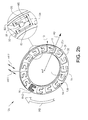
- Fig. 2b discloses another exemplary embodiment of a pressure control device 10b.
- the through holes 13b of the exemplary embodiment disclosed in fig. 2b are turned 180 degrees, such that the protrusion 30b is extending in opposite direction then of the exemplary embodiment of fig. 2a , in relation to the intended rotational direction.
- a portion of the circumferential inner surface 14 of respective through hole 13b opposite the intended rotational direction IRD of the pressure control device 10 is provided with a protrusion 30b extending into the through hole 13b.
- Fig. 2c discloses yet another exemplary embodiment of a pressure control device 10c.
- the through holes 13c of fig. 2c are provided with two protrusions 30, 30b, wherein a first protrusion 30 extends from the circumferential inner surface 14 of respective through hole 13c in the intended rotational direction IRD of the pressure control device 10c and a second protrusion 30b extends from the circumferential inner surface 14 of respective through hole 13c opposite the intended rotational direction IRD of the pressure control device 10c, such that respective through hole 13c essentially is in form of a cross-section of an I-beam.
- the midsection MS significantly narrower than adjacent outer section OS and inner section IS.
- an exemplary advantage with through holes 13c configured according to the exemplary embodiment of fig. 2c is that this enables that the angular distance, thus period of time, the through hole 13c is completely blocked by a land to be varied.
- Fig, 2a . 2b and 2c discloses preferred exemplary embodiments of pressure control devices 10.
- other configurations e.g. other configurations of the through holes, the protrusions or the slots, providing essentially the same functionality, are also realizable and thereby considered to be within the scope of the present disclosure.
- Fig. 3 discloses an exemplary embodiment of a pressure control device 10 and of a control ring 3.
- the exemplary embodiment of the pressure control device 10 corresponds to the exemplary embodiment of the pressure control device 10 disclosed in relation to fig. 1 and 2a to 2c , wherein the pressure control device 10 is arranged along the first rotational axis ax1.
- the exemplary embodiment of the control ring 3 corresponds to the exemplary embodiment of the control ring 3 disclosed in relation to fig. 1 .
- the control ring 3 is rotational symmetric about the second rotational axis ax2, wherein the second rotational axis ax2 is radially offset by a distance E in relation to the first rotational axis ax1.
- the control ring is further provided with a high pressure side HP and a low pressure side LP.
- the low pressure side LP is provided with at least a semi-circular arc shaped first opening 35 and the high pressure side HP is provided with at least a semi-circular arc shaped second opening 36.
- the second opening 36 is divided into three openings due to durability reasons. At least an end portion of the first opening 35 and of the second openings 36 has a radial width B3.
- the whole extension of as well the first opening 35 as of the second opening 36 has the radial width B3.
- the first and second openings 35, 36 are separated by a first land 33 and a second land 34. Further, the second opening 36 is in fluid communication with the outlet 39 and the first opening 35 is in fluid communication with the inlet 38.
- the pumping arrangement 1 as disclosed in fig. 1 comprising the control ring 3
- the present inlet 38 may be used as an outlet and the present outlet 39 may be used as an inlet.
- the exemplary embodiment of a pressure control device 10 disclosed in fig. 3 corresponds to the exemplary embodiment of a pressure control device of fig. 2a , wherein the pressure control device has a first axial surface 11 and a second axial surface 12, wherein the second axial surface 12 is facing the control ring 3, and wherein the pressure control device 10 is provided with a number of through holes 13.
- the through holes 13 are formed with protrusions 30 extending from an inner circumferential surface 14 of respective through hole 13 in an intended rotational direction IRD of the pressure control device 10.
- the through holes 13 are further formed to have a first and a second slot 31, 32 on a first and second radial side of the protrusions 13.
- the protrusion 30 has a radial width B1 and the first and second slot 31, 32 have a radial width B2.
- the width B1 is essentially equal to B3.
- the first and the second opening 35, 36 of the control ring 3 is fluidly connected to the inlet 38 and the outlet 39, wherein the inlet 38 and the outlet 39 are provided at different axial distance from an axial surface 300 of the control ring 3.
- the different axial distance is important in order to create two separate areas between a radial outer surface of the control ring 3 and an inner radial surface of an enclosing rear housing 7b.
- a first, a second and a third seal ring 301, 302, 303 is provided in order to create these separate areas.
- One of the inlet and outlet 38, 39 is connected to a respective separated area between the seal rings 301, 302, 303.
- the control ring 3 is further provided with a gearing 18 used to adjust the displacement of the control ring 3. Since offset E between the first rotational axis ax1 in relation to the second rotational axis ax2 the displacement of the control ring 3 in relation to the pressure control device 10, and due to the configuration of the through holes 13 with protrusions 30, the displacement of the control ring will affect how long respective first and second lands 33, 34 completely blocks the through holes 13 during operation when the pressure control device 10 rotates in relation to the control ring 3. This will be disclosed more in detail in relation to fig. 5a-5f .
- Fig. 4 discloses that the first axial surface of an exemplary embodiment of a pressure control device 10b is fixedly arranged to an axial surface 400 of the rear face of a pump unit 6c.
- a second axial surface 12 of the pressure control device 10b arranged on opposite axial side than the first axial surface of the control device 10b, is facing away from the rear face of a pump unit 6c.
- the rear face of the pump unit 6c and the pressure control device 10b are centred along the first rotational axis ax1.
- the pressure control device 10b may be fixedly arranged to the axial surface 400 of the rear face of a pump unit 6c or an integrated part of the rear face of a pump unit 6c.
- the rear face of a pump unit 6c disclosed in fig. 4 belongs to an improved piston displacement pump and is defined as a rear portion, which is essentially equal independently on which pump unit that is applied, of a cylinder plate 22c.
- the improved piston displacement pump further comprises a swashplate 21c with pistons 42, wherein the pistons 42 are configured for reciprocating in cylinders.
- the pistons 42 reciprocates within the cylinders as the swashplate 21c and the cylinder plate 22c rotates due to the skew arrangement of the swashplate 21c in relation to the cylinder plate 22c.
- the cylinders of the improved piston displacement pump are herein generically referred to as pressure chambers 25c.
- the pressure control device 10b is provided with one through hole 13b for each pressure chamber 25c (cylinder).
- An axis 23c is extending through the swashplate 21c and the cylinder plate 22c comprising the pressure control device 10b, wherein the cylinder plate 22c is fixedly arranged, e.g. by splines, to the axis 23c and the swashplate 21c is arranged to rotate freely in relation to the axis 23c.
- a first radial cross-sectional area RA1 of the pressure chamber 25c (cylinder) which is essentially equal to a radial cross-sectional area RA1 of the piston 42, is essentially equal to a second radial cross-sectional area RA2 of respective through hole 13.
- the first radial cross-sectional area RA1 of the pressure chamber 25c (cylinder)/piston 42 is defined by the an outer circumferential edge 43 of the piston 42/an inner wall 43 of the pressure chamber 25c (cylinder) whereas the second radial cross-sectional area RA2 of the through holes 13b are, as previously disclosed, defined by the outer edge 16 of the circumferential inner surface 14 of the through hole 13.
- Respective pressure chamber 25c (cylinder) is arranged to be in fluid communication with respective through hole 13b via pressure chamber outlet 44.
- the pressure chamber outlet 44 is defined as a passage opening up respective pressure chamber 25c (cylinder) at an end opposite to the end where respective piston 42 enters respective pressure chamber 25c (cylinder).
- Fig. 5a discloses the control ring 3 and the pressure control device 10 as it interacts with the control ring 3.
- the pressure control device 10 is centred about the first rotational axis ax1 of the pumping arrangement 1, whereby the control ring 3 is eccentric arranged relative the rear pressure control device 10 and is centred about the second rotational axis ax2.
- the first and second rotational axes ax1, ax2 are separated by a distance E.
- the through holes 13 can be seen.
- the pressure control device 10 and the cylinder plate to which the pressure control device 10 is arranged etc. rotates with the first rotational axis ax1 in the intended rotational direction IRD, whereas the control ring is stationary.
- the pumping arrangement 1 is in the same position.
- the pressure control device 10 is transparently depicted wherein the semi-circular, low pressure first opening 35 and the semi-circular, high pressure second opening 36 are visible.
- the first and second openings 35, 36 opens up to pressure chambers of the pressure control device 10.
- the second opening 36 also opens up to the outlet whereas first opening 35 also opens up to the inlet.
- the control ring 3 can be turned to change the displacement by means of the actuator pin 8 interacting with the gearing 18, in order to change the displacement of the pumping arrangement 1, and thereby also change the position of the first and the second land 33, 34.
- the through holes 13 are completely blocked by the first and the second land 33, 34 respectively.
- the blocking is necessary to avoid that the low pressure first opening 35 is connected to the high pressure second opening 36 of the control ring.
- a pressure rise/pressure drop in the through holes 13 occurs, because of the blocking.
- the control ring 3 is positioned such that the first land and the second land 33, 34 are positioned in between the high pressure side HP and the low pressure side LP.
- the pumping arrangement 1 is controlled to deliver 100% displacement.
- the pressure rises/decreases slowly. This means that a small pressure increase occurs for each angular distance a blocked through hole 13a moves over the first land 33 and a small pressure decrease occurs for each angular distance a blocked through hole 13a moves over the second land 34.
- the illustrated through hole 13 is in a position where it just became fully blocked by the first land 33. In this position no pressure medium can be provided out from the through hole 13.
- no pressure medium can be provided out from the through hole 13
- no pressure medium which is provided to the through hole 13 by that the piston exerts pressure on pressure medium of the pressure chamber, which forces pressure medium into the through hole 13 of the pressure control device 10 via the pressure chamber outlet, may flow into the second opening 36 of the control ring 3.
- the control ring 3 is still in the same position as in figure 5b , however, in fig. 5c the pressure control device 10 has rotated a bit further wherein the illustrated through hole 13 is in a position such that it is just about to open up to the second opening 36, i.e. not be fully blocked by the first land 33 anymore.
- the pressure control device 10 has thereby moved a first angular distance AD1 between fig. 5b and fig. 5c .
- the first angular distance AD1 is the angular distance the through hole 13a moves over the first land 33 and is fully blocked thereby, when the control ring 3 is positioned in a position for 100% displacement.
- fig. 5d and 5e disclosing an exemplary embodiment where the control ring 3 has been turned 90 degrees in a counter clockwise direction, and is positioned in a position for 0% displacement.
- the through hole 13 is in a position where it just became fully blocked by the first land 33.
- the pressure control device 10 has moved a second angular distance AD2 between fig. 5d and fig. 5e .
- the through hole 13 will be completely blocked by the first land 33 for a significantly shorter period of time when the control ring is in a position for 0% displacement, as is disclosed in fig. 5d and 5e , than when the control ring is in a position for 100% displacement, as is disclosed in fig. 5b and 5c .
- fig. 5f which corresponds to the exemplary embodiments of fig. 5d and 5e , but with a differently configured control ring 3
- the control ring 3 is arranged in a position for a 0% displacement and the through hole 13 is in a position where it just became fully blocked by the first land 33.
- the through hole 13 will open up to the second opening 360.
- the through hole 13 will be completely blocked by the first land 33 only at one angle.
- the angular distance between a complete blocking of the through hole 13 and the reopening is zero, whereby no additional pressure will be able to be build up during the passing of the first land 33.
- the pressure control arrangement 5 and the pumping arrangement 1 disclosed herein is the angular distance the through holes 13, 13b, 13c travels over the first land 33 and is fully blocked in relation to the displacement and the pressure built up during that a pressure chamber passes of a land at that displacement.
- the angular distance the through holes 13, 13b, 13c travels can be varied dependent on the position of the control ring 3 due to that the control ring 3 is eccentrically arranged relative the pressure control device 10, the pressure control arrangement 5 and the pumping arrangement 1, and due to the unique design of the through holes 1313b, 13c.
- other designs of the through holes may give the same functionality as the exemplary design disclosed herein. Such designs, providing the same exemplary advantage, are considered to be within the scope of the present invention.
Landscapes
- Engineering & Computer Science (AREA)
- Mechanical Engineering (AREA)
- General Engineering & Computer Science (AREA)
- Chemical & Material Sciences (AREA)
- Combustion & Propulsion (AREA)
- Details And Applications Of Rotary Liquid Pumps (AREA)
Priority Applications (1)
| Application Number | Priority Date | Filing Date | Title |
|---|---|---|---|
| EP15187889.9A EP3150851B1 (fr) | 2015-10-01 | 2015-10-01 | Pompe volumétrique améliorée |
Applications Claiming Priority (1)
| Application Number | Priority Date | Filing Date | Title |
|---|---|---|---|
| EP15187889.9A EP3150851B1 (fr) | 2015-10-01 | 2015-10-01 | Pompe volumétrique améliorée |
Publications (2)
| Publication Number | Publication Date |
|---|---|
| EP3150851A1 true EP3150851A1 (fr) | 2017-04-05 |
| EP3150851B1 EP3150851B1 (fr) | 2019-12-25 |
Family
ID=54260635
Family Applications (1)
| Application Number | Title | Priority Date | Filing Date |
|---|---|---|---|
| EP15187889.9A Active EP3150851B1 (fr) | 2015-10-01 | 2015-10-01 | Pompe volumétrique améliorée |
Country Status (1)
| Country | Link |
|---|---|
| EP (1) | EP3150851B1 (fr) |
Cited By (1)
| Publication number | Priority date | Publication date | Assignee | Title |
|---|---|---|---|---|
| US10968741B2 (en) | 2019-02-08 | 2021-04-06 | Volvo Car Corporation | Variable pre and de-compression control mechanism and method for hydraulic displacement pump |
Citations (4)
| Publication number | Priority date | Publication date | Assignee | Title |
|---|---|---|---|---|
| US3369458A (en) * | 1966-07-05 | 1968-02-20 | Dowty Technical Dev Ltd | Hydraulic apparatus |
| US5103642A (en) * | 1990-07-12 | 1992-04-14 | Fuji Tekko Co., Ltd. | Rotary shaft coupler with rotary valve plate position dependent on direction of shaft rotation |
| WO1999054625A1 (fr) * | 1998-04-07 | 1999-10-28 | Caterpillar Inc. | Plateau de distribution a regulation pour convertisseur de pression |
| US6038958A (en) * | 1998-04-07 | 2000-03-21 | Noax B.V. | Porting for hydraulic pressure transformer |
-
2015
- 2015-10-01 EP EP15187889.9A patent/EP3150851B1/fr active Active
Patent Citations (4)
| Publication number | Priority date | Publication date | Assignee | Title |
|---|---|---|---|---|
| US3369458A (en) * | 1966-07-05 | 1968-02-20 | Dowty Technical Dev Ltd | Hydraulic apparatus |
| US5103642A (en) * | 1990-07-12 | 1992-04-14 | Fuji Tekko Co., Ltd. | Rotary shaft coupler with rotary valve plate position dependent on direction of shaft rotation |
| WO1999054625A1 (fr) * | 1998-04-07 | 1999-10-28 | Caterpillar Inc. | Plateau de distribution a regulation pour convertisseur de pression |
| US6038958A (en) * | 1998-04-07 | 2000-03-21 | Noax B.V. | Porting for hydraulic pressure transformer |
Cited By (2)
| Publication number | Priority date | Publication date | Assignee | Title |
|---|---|---|---|---|
| US10968741B2 (en) | 2019-02-08 | 2021-04-06 | Volvo Car Corporation | Variable pre and de-compression control mechanism and method for hydraulic displacement pump |
| US11306589B2 (en) | 2019-02-08 | 2022-04-19 | Volvo Construction Equipment Ab | Mechanism and method for a high efficiency low noise hydraulic pump/motor |
Also Published As
| Publication number | Publication date |
|---|---|
| EP3150851B1 (fr) | 2019-12-25 |
Similar Documents
| Publication | Publication Date | Title |
|---|---|---|
| EP2828525B1 (fr) | Pompe rotative à cylindrée variable et procédé de commande de la cylindrée | |
| US10550840B2 (en) | Vane pump device | |
| JP2013527379A (ja) | 可変容積形潤滑剤ポンプ | |
| US20110038746A1 (en) | Variable-volume internal gear pump | |
| JP6608673B2 (ja) | ベーンポンプ装置 | |
| EP2960510A1 (fr) | Pompe à palettes à capacité variable | |
| CN107002672A (zh) | 可变容量式叶片泵 | |
| CN106884791B (zh) | 叶片泵装置 | |
| EP3135913B1 (fr) | Pompe à cylindrée variable | |
| EP3150851A1 (fr) | Pompe volumétrique améliorée | |
| EP1536138A1 (fr) | Machine a rotor | |
| CN106968944B (zh) | 叶片泵装置 | |
| JPH04265484A (ja) | タンデムポンプ | |
| JP6670119B2 (ja) | ベーンポンプ | |
| JP6615579B2 (ja) | ベーンポンプ装置 | |
| EP2894295B1 (fr) | Anneau de commande pour pompe volumétrique et pompe volumétrique | |
| EP2894294B1 (fr) | Bague de control pour un dispositif hydrostatiques | |
| US10731646B2 (en) | Vane pump device having two different discharge amounts | |
| JP6615580B2 (ja) | ベーンポンプ装置、油圧装置 | |
| CN1573112A (zh) | 滚子叶片泵 | |
| JP2846340B2 (ja) | 可変容量型ベーンオイルポンプ | |
| US10655624B2 (en) | Vane pump device for controlling deviation of a force applied to the vanes | |
| CN106917745B (zh) | 叶片泵装置 | |
| CN107061262B (zh) | 叶片泵装置 | |
| JP2017110573A (ja) | 油圧装置、油圧式無段変速機 |
Legal Events
| Date | Code | Title | Description |
|---|---|---|---|
| PUAI | Public reference made under article 153(3) epc to a published international application that has entered the european phase |
Free format text: ORIGINAL CODE: 0009012 |
|
| STAA | Information on the status of an ep patent application or granted ep patent |
Free format text: STATUS: THE APPLICATION HAS BEEN PUBLISHED |
|
| AK | Designated contracting states |
Kind code of ref document: A1 Designated state(s): AL AT BE BG CH CY CZ DE DK EE ES FI FR GB GR HR HU IE IS IT LI LT LU LV MC MK MT NL NO PL PT RO RS SE SI SK SM TR |
|
| AX | Request for extension of the european patent |
Extension state: BA ME |
|
| STAA | Information on the status of an ep patent application or granted ep patent |
Free format text: STATUS: REQUEST FOR EXAMINATION WAS MADE |
|
| 17P | Request for examination filed |
Effective date: 20171005 |
|
| RBV | Designated contracting states (corrected) |
Designated state(s): AL AT BE BG CH CY CZ DE DK EE ES FI FR GB GR HR HU IE IS IT LI LT LU LV MC MK MT NL NO PL PT RO RS SE SI SK SM TR |
|
| GRAP | Despatch of communication of intention to grant a patent |
Free format text: ORIGINAL CODE: EPIDOSNIGR1 |
|
| STAA | Information on the status of an ep patent application or granted ep patent |
Free format text: STATUS: GRANT OF PATENT IS INTENDED |
|
| INTG | Intention to grant announced |
Effective date: 20190718 |
|
| GRAS | Grant fee paid |
Free format text: ORIGINAL CODE: EPIDOSNIGR3 |
|
| GRAA | (expected) grant |
Free format text: ORIGINAL CODE: 0009210 |
|
| STAA | Information on the status of an ep patent application or granted ep patent |
Free format text: STATUS: THE PATENT HAS BEEN GRANTED |
|
| RAP1 | Party data changed (applicant data changed or rights of an application transferred) |
Owner name: MOOG GMBH |
|
| AK | Designated contracting states |
Kind code of ref document: B1 Designated state(s): AL AT BE BG CH CY CZ DE DK EE ES FI FR GB GR HR HU IE IS IT LI LT LU LV MC MK MT NL NO PL PT RO RS SE SI SK SM TR |
|
| REG | Reference to a national code |
Ref country code: GB Ref legal event code: FG4D |
|
| REG | Reference to a national code |
Ref country code: CH Ref legal event code: EP |
|
| REG | Reference to a national code |
Ref country code: AT Ref legal event code: REF Ref document number: 1217406 Country of ref document: AT Kind code of ref document: T Effective date: 20200115 |
|
| REG | Reference to a national code |
Ref country code: DE Ref legal event code: R096 Ref document number: 602015044174 Country of ref document: DE |
|
| REG | Reference to a national code |
Ref country code: IE Ref legal event code: FG4D |
|
| REG | Reference to a national code |
Ref country code: NL Ref legal event code: MP Effective date: 20191225 |
|
| PG25 | Lapsed in a contracting state [announced via postgrant information from national office to epo] |
Ref country code: LT Free format text: LAPSE BECAUSE OF FAILURE TO SUBMIT A TRANSLATION OF THE DESCRIPTION OR TO PAY THE FEE WITHIN THE PRESCRIBED TIME-LIMIT Effective date: 20191225 Ref country code: GR Free format text: LAPSE BECAUSE OF FAILURE TO SUBMIT A TRANSLATION OF THE DESCRIPTION OR TO PAY THE FEE WITHIN THE PRESCRIBED TIME-LIMIT Effective date: 20200326 Ref country code: NO Free format text: LAPSE BECAUSE OF FAILURE TO SUBMIT A TRANSLATION OF THE DESCRIPTION OR TO PAY THE FEE WITHIN THE PRESCRIBED TIME-LIMIT Effective date: 20200325 Ref country code: SE Free format text: LAPSE BECAUSE OF FAILURE TO SUBMIT A TRANSLATION OF THE DESCRIPTION OR TO PAY THE FEE WITHIN THE PRESCRIBED TIME-LIMIT Effective date: 20191225 Ref country code: LV Free format text: LAPSE BECAUSE OF FAILURE TO SUBMIT A TRANSLATION OF THE DESCRIPTION OR TO PAY THE FEE WITHIN THE PRESCRIBED TIME-LIMIT Effective date: 20191225 Ref country code: BG Free format text: LAPSE BECAUSE OF FAILURE TO SUBMIT A TRANSLATION OF THE DESCRIPTION OR TO PAY THE FEE WITHIN THE PRESCRIBED TIME-LIMIT Effective date: 20200325 Ref country code: FI Free format text: LAPSE BECAUSE OF FAILURE TO SUBMIT A TRANSLATION OF THE DESCRIPTION OR TO PAY THE FEE WITHIN THE PRESCRIBED TIME-LIMIT Effective date: 20191225 |
|
| REG | Reference to a national code |
Ref country code: LT Ref legal event code: MG4D |
|
| PG25 | Lapsed in a contracting state [announced via postgrant information from national office to epo] |
Ref country code: RS Free format text: LAPSE BECAUSE OF FAILURE TO SUBMIT A TRANSLATION OF THE DESCRIPTION OR TO PAY THE FEE WITHIN THE PRESCRIBED TIME-LIMIT Effective date: 20191225 Ref country code: HR Free format text: LAPSE BECAUSE OF FAILURE TO SUBMIT A TRANSLATION OF THE DESCRIPTION OR TO PAY THE FEE WITHIN THE PRESCRIBED TIME-LIMIT Effective date: 20191225 |
|
| PG25 | Lapsed in a contracting state [announced via postgrant information from national office to epo] |
Ref country code: AL Free format text: LAPSE BECAUSE OF FAILURE TO SUBMIT A TRANSLATION OF THE DESCRIPTION OR TO PAY THE FEE WITHIN THE PRESCRIBED TIME-LIMIT Effective date: 20191225 |
|
| PG25 | Lapsed in a contracting state [announced via postgrant information from national office to epo] |
Ref country code: EE Free format text: LAPSE BECAUSE OF FAILURE TO SUBMIT A TRANSLATION OF THE DESCRIPTION OR TO PAY THE FEE WITHIN THE PRESCRIBED TIME-LIMIT Effective date: 20191225 Ref country code: NL Free format text: LAPSE BECAUSE OF FAILURE TO SUBMIT A TRANSLATION OF THE DESCRIPTION OR TO PAY THE FEE WITHIN THE PRESCRIBED TIME-LIMIT Effective date: 20191225 Ref country code: RO Free format text: LAPSE BECAUSE OF FAILURE TO SUBMIT A TRANSLATION OF THE DESCRIPTION OR TO PAY THE FEE WITHIN THE PRESCRIBED TIME-LIMIT Effective date: 20191225 Ref country code: CZ Free format text: LAPSE BECAUSE OF FAILURE TO SUBMIT A TRANSLATION OF THE DESCRIPTION OR TO PAY THE FEE WITHIN THE PRESCRIBED TIME-LIMIT Effective date: 20191225 Ref country code: PT Free format text: LAPSE BECAUSE OF FAILURE TO SUBMIT A TRANSLATION OF THE DESCRIPTION OR TO PAY THE FEE WITHIN THE PRESCRIBED TIME-LIMIT Effective date: 20200520 |
|
| PG25 | Lapsed in a contracting state [announced via postgrant information from national office to epo] |
Ref country code: SM Free format text: LAPSE BECAUSE OF FAILURE TO SUBMIT A TRANSLATION OF THE DESCRIPTION OR TO PAY THE FEE WITHIN THE PRESCRIBED TIME-LIMIT Effective date: 20191225 Ref country code: SK Free format text: LAPSE BECAUSE OF FAILURE TO SUBMIT A TRANSLATION OF THE DESCRIPTION OR TO PAY THE FEE WITHIN THE PRESCRIBED TIME-LIMIT Effective date: 20191225 Ref country code: IS Free format text: LAPSE BECAUSE OF FAILURE TO SUBMIT A TRANSLATION OF THE DESCRIPTION OR TO PAY THE FEE WITHIN THE PRESCRIBED TIME-LIMIT Effective date: 20200425 |
|
| REG | Reference to a national code |
Ref country code: DE Ref legal event code: R097 Ref document number: 602015044174 Country of ref document: DE |
|
| PG25 | Lapsed in a contracting state [announced via postgrant information from national office to epo] |
Ref country code: ES Free format text: LAPSE BECAUSE OF FAILURE TO SUBMIT A TRANSLATION OF THE DESCRIPTION OR TO PAY THE FEE WITHIN THE PRESCRIBED TIME-LIMIT Effective date: 20191225 Ref country code: DK Free format text: LAPSE BECAUSE OF FAILURE TO SUBMIT A TRANSLATION OF THE DESCRIPTION OR TO PAY THE FEE WITHIN THE PRESCRIBED TIME-LIMIT Effective date: 20191225 |
|
| PLBE | No opposition filed within time limit |
Free format text: ORIGINAL CODE: 0009261 |
|
| STAA | Information on the status of an ep patent application or granted ep patent |
Free format text: STATUS: NO OPPOSITION FILED WITHIN TIME LIMIT |
|
| REG | Reference to a national code |
Ref country code: AT Ref legal event code: MK05 Ref document number: 1217406 Country of ref document: AT Kind code of ref document: T Effective date: 20191225 |
|
| PG25 | Lapsed in a contracting state [announced via postgrant information from national office to epo] |
Ref country code: SI Free format text: LAPSE BECAUSE OF FAILURE TO SUBMIT A TRANSLATION OF THE DESCRIPTION OR TO PAY THE FEE WITHIN THE PRESCRIBED TIME-LIMIT Effective date: 20191225 |
|
| 26N | No opposition filed |
Effective date: 20200928 |
|
| PG25 | Lapsed in a contracting state [announced via postgrant information from national office to epo] |
Ref country code: IT Free format text: LAPSE BECAUSE OF FAILURE TO SUBMIT A TRANSLATION OF THE DESCRIPTION OR TO PAY THE FEE WITHIN THE PRESCRIBED TIME-LIMIT Effective date: 20191225 Ref country code: AT Free format text: LAPSE BECAUSE OF FAILURE TO SUBMIT A TRANSLATION OF THE DESCRIPTION OR TO PAY THE FEE WITHIN THE PRESCRIBED TIME-LIMIT Effective date: 20191225 |
|
| PG25 | Lapsed in a contracting state [announced via postgrant information from national office to epo] |
Ref country code: PL Free format text: LAPSE BECAUSE OF FAILURE TO SUBMIT A TRANSLATION OF THE DESCRIPTION OR TO PAY THE FEE WITHIN THE PRESCRIBED TIME-LIMIT Effective date: 20191225 |
|
| REG | Reference to a national code |
Ref country code: CH Ref legal event code: PL |
|
| GBPC | Gb: european patent ceased through non-payment of renewal fee |
Effective date: 20201001 |
|
| PG25 | Lapsed in a contracting state [announced via postgrant information from national office to epo] |
Ref country code: LU Free format text: LAPSE BECAUSE OF NON-PAYMENT OF DUE FEES Effective date: 20201001 Ref country code: MC Free format text: LAPSE BECAUSE OF FAILURE TO SUBMIT A TRANSLATION OF THE DESCRIPTION OR TO PAY THE FEE WITHIN THE PRESCRIBED TIME-LIMIT Effective date: 20191225 |
|
| REG | Reference to a national code |
Ref country code: BE Ref legal event code: MM Effective date: 20201031 |
|
| PG25 | Lapsed in a contracting state [announced via postgrant information from national office to epo] |
Ref country code: FR Free format text: LAPSE BECAUSE OF NON-PAYMENT OF DUE FEES Effective date: 20201031 |
|
| PG25 | Lapsed in a contracting state [announced via postgrant information from national office to epo] |
Ref country code: LI Free format text: LAPSE BECAUSE OF NON-PAYMENT OF DUE FEES Effective date: 20201031 Ref country code: GB Free format text: LAPSE BECAUSE OF NON-PAYMENT OF DUE FEES Effective date: 20201001 Ref country code: CH Free format text: LAPSE BECAUSE OF NON-PAYMENT OF DUE FEES Effective date: 20201031 Ref country code: BE Free format text: LAPSE BECAUSE OF NON-PAYMENT OF DUE FEES Effective date: 20201031 |
|
| PG25 | Lapsed in a contracting state [announced via postgrant information from national office to epo] |
Ref country code: IE Free format text: LAPSE BECAUSE OF NON-PAYMENT OF DUE FEES Effective date: 20201001 |
|
| PG25 | Lapsed in a contracting state [announced via postgrant information from national office to epo] |
Ref country code: TR Free format text: LAPSE BECAUSE OF FAILURE TO SUBMIT A TRANSLATION OF THE DESCRIPTION OR TO PAY THE FEE WITHIN THE PRESCRIBED TIME-LIMIT Effective date: 20191225 Ref country code: MT Free format text: LAPSE BECAUSE OF FAILURE TO SUBMIT A TRANSLATION OF THE DESCRIPTION OR TO PAY THE FEE WITHIN THE PRESCRIBED TIME-LIMIT Effective date: 20191225 Ref country code: CY Free format text: LAPSE BECAUSE OF FAILURE TO SUBMIT A TRANSLATION OF THE DESCRIPTION OR TO PAY THE FEE WITHIN THE PRESCRIBED TIME-LIMIT Effective date: 20191225 |
|
| PG25 | Lapsed in a contracting state [announced via postgrant information from national office to epo] |
Ref country code: MK Free format text: LAPSE BECAUSE OF FAILURE TO SUBMIT A TRANSLATION OF THE DESCRIPTION OR TO PAY THE FEE WITHIN THE PRESCRIBED TIME-LIMIT Effective date: 20191225 |
|
| PGFP | Annual fee paid to national office [announced via postgrant information from national office to epo] |
Ref country code: DE Payment date: 20231020 Year of fee payment: 9 |