EP3150487A1 - Axle saddle - Google Patents
Axle saddle Download PDFInfo
- Publication number
- EP3150487A1 EP3150487A1 EP16191533.5A EP16191533A EP3150487A1 EP 3150487 A1 EP3150487 A1 EP 3150487A1 EP 16191533 A EP16191533 A EP 16191533A EP 3150487 A1 EP3150487 A1 EP 3150487A1
- Authority
- EP
- European Patent Office
- Prior art keywords
- saddle
- undercut
- axle
- strap
- bearing land
- Prior art date
- Legal status (The legal status is an assumption and is not a legal conclusion. Google has not performed a legal analysis and makes no representation as to the accuracy of the status listed.)
- Granted
Links
- 230000004323 axial length Effects 0.000 claims description 23
- 238000000034 method Methods 0.000 claims description 23
- 238000003780 insertion Methods 0.000 claims description 4
- 230000037431 insertion Effects 0.000 claims description 4
- 229910001220 stainless steel Inorganic materials 0.000 claims description 4
- 239000010935 stainless steel Substances 0.000 claims description 4
- 238000009434 installation Methods 0.000 abstract description 5
- 230000007704 transition Effects 0.000 description 15
- 230000008901 benefit Effects 0.000 description 6
- 230000008569 process Effects 0.000 description 3
- 230000005494 condensation Effects 0.000 description 1
- 238000009833 condensation Methods 0.000 description 1
- 238000012423 maintenance Methods 0.000 description 1
- 239000000463 material Substances 0.000 description 1
- 230000007246 mechanism Effects 0.000 description 1
- 239000002184 metal Substances 0.000 description 1
- 230000008439 repair process Effects 0.000 description 1
- 239000000126 substance Substances 0.000 description 1
- 239000013585 weight reducing agent Substances 0.000 description 1
Images


Classifications
-
- B—PERFORMING OPERATIONS; TRANSPORTING
- B64—AIRCRAFT; AVIATION; COSMONAUTICS
- B64C—AEROPLANES; HELICOPTERS
- B64C25/00—Alighting gear
- B64C25/32—Alighting gear characterised by elements which contact the ground or similar surface
- B64C25/34—Alighting gear characterised by elements which contact the ground or similar surface wheeled type, e.g. multi-wheeled bogies
- B64C25/36—Arrangements or adaptations of wheels, tyres or axles in general
-
- B—PERFORMING OPERATIONS; TRANSPORTING
- B60—VEHICLES IN GENERAL
- B60B—VEHICLE WHEELS; CASTORS; AXLES FOR WHEELS OR CASTORS; INCREASING WHEEL ADHESION
- B60B35/00—Axle units; Parts thereof ; Arrangements for lubrication of axles
- B60B35/02—Dead axles, i.e. not transmitting torque
- B60B35/025—Dead axles, i.e. not transmitting torque the wheels being removable
-
- B—PERFORMING OPERATIONS; TRANSPORTING
- B64—AIRCRAFT; AVIATION; COSMONAUTICS
- B64F—GROUND OR AIRCRAFT-CARRIER-DECK INSTALLATIONS SPECIALLY ADAPTED FOR USE IN CONNECTION WITH AIRCRAFT; DESIGNING, MANUFACTURING, ASSEMBLING, CLEANING, MAINTAINING OR REPAIRING AIRCRAFT, NOT OTHERWISE PROVIDED FOR; HANDLING, TRANSPORTING, TESTING OR INSPECTING AIRCRAFT COMPONENTS, NOT OTHERWISE PROVIDED FOR
- B64F5/00—Designing, manufacturing, assembling, cleaning, maintaining or repairing aircraft, not otherwise provided for; Handling, transporting, testing or inspecting aircraft components, not otherwise provided for
- B64F5/10—Manufacturing or assembling aircraft, e.g. jigs therefor
-
- B—PERFORMING OPERATIONS; TRANSPORTING
- B60—VEHICLES IN GENERAL
- B60B—VEHICLE WHEELS; CASTORS; AXLES FOR WHEELS OR CASTORS; INCREASING WHEEL ADHESION
- B60B2340/00—Wheel transporting, Mounting of wheels
-
- B—PERFORMING OPERATIONS; TRANSPORTING
- B60—VEHICLES IN GENERAL
- B60B—VEHICLE WHEELS; CASTORS; AXLES FOR WHEELS OR CASTORS; INCREASING WHEEL ADHESION
- B60B2900/00—Purpose of invention
- B60B2900/20—Avoidance of
- B60B2900/212—Damage
Definitions
- Aircraft axles may have an undercut between the bearing lands, e.g., for weight reduction or other design considerations. Assembly and installation or removal of a wheel assembly onto such an axle may subject the axle and bearing assembly to damage such as dislodging of the bearing assembly. Damage may occur, for example, as the bearing assembly tilts and impacts the axle undercut or bearing lands. This may lead to bearing failures, damaged wheels and/or lost wheels.
- an axle saddle system comprising:
- an axle method comprising: inserting a saddle over an undercut of an axle, and tightening the saddle around the undercut, wherein the axle comprises an outboard bearing land and an inboard bearing land, wherein the undercut is situated between the outboard bearing land and the inboard bearing land and is radially tapered with respect to at least one of the outboard bearing land and the inboard bearing land, and wherein the saddle is configured to substantially fill the undercut over a surface area of the undercut, such that the substantially filled undercut is substantially level with the outboard bearing land and the inboard bearing land, wherein the undercut comprises an undercut perimeter and an undercut axial length forming the surface area of the undercut, and wherein the saddle has a saddle axial length approximately equal to the undercut axial length.
- the axle method further comprises tightening the saddle around the undercut with at least one saddle strap. In one embodiment, the axle method further comprises prying the saddle open before inserting. In one embodiment, the saddle strap comprises a buckle and a strap end, the axle saddle method further comprising inserting the strap end through the buckle, pulling the strap end to tighten the saddle strap around the saddle, and breaking off an excess portion of the saddle strap.
- an axle saddle system comprising: a saddle configured to substantially cover an undercut of an axle over a surface area of the undercut, and a saddle strap configured to tighten the saddle around the undercut, wherein the undercut is situated between an outboard bearing land and an inboard bearing land of the axle, wherein the undercut is radially tapered with respect to the outboard bearing land and the inboard bearing land, wherein the undercut comprises an undercut perimeter and an undercut axial length forming the surface area of the undercut, wherein the saddle has a saddle axial length approximately equal to the undercut axial length, and a saddle perimeter configured to span at least 315 degrees of the undercut perimeter, wherein the saddle is configured to substantially fill the undercut, such that the substantially filled undercut has a profile which is substantially level with the outboard bearing land and the inboard bearing land, wherein the saddle comprises a strap channel, and wherein the saddle strap is configured to nest within the strap channel.
- the saddle and saddle strap are metallic.
- an axle saddle system 100 for an axle 101 having an undercut between the outboard and inboard bearing lands comprising a saddle configured to fill the axle undercut in order to protect the axle 101 from damage by the installation of a wheel onto the axle.
- axle 101 may be a wheel axle, and may comprise an outboard bearing land 102, an inboard bearing land 104, and an axle shaft 106 between the outboard bearing land 102 and inboard bearing land 104.
- the outboard bearing land 102, and the inboard bearing land 104 are each configured to receive a bearing assembly 200 of a wheel 202 (e.g. an aircraft wheel), as shown in Figure 1B .
- the bearing assembly 200 comprises an outboard bearing 204 configured to rotationally engage with the outboard bearing land 102, and an inboard bearing 206 configured to rotationally engage with the inboard bearing land 104.
- outboard bearing 204, and inboard bearing 206 may comprising, for example, tapered roller bearings.
- the axle shaft 106 is typically radially tapered with respect to at least one of the outboard bearing land 102 and inboard bearing land 104 to form an undercut axle shaft or axle undercut 107 between the outboard bearing land 102 and inboard bearing land 104.
- the axle undercut 107 may be tapered with respect to both the outboard bearing land 102, and inboard bearing land 104, with an outboard transition wall 103 between the outboard bearing land 102 and axle undercut 107, and an inboard transition wall 105 between the inboard bearing land 104 and axle undercut 107, as shown in Figures 1A and 1B .
- the outboard transition wall 103 spans radially outwards from the axle undercut 107 to the outboard bearing land 102, and the inboard transition wall 105 spans radially outwards from the axle undercut 107 to the outboard bearing land 102.
- the outboard transition wall 103, and the inboard transition wall 105 may each have various configurations, such as tapered, straight, etc., according to various embodiments.
- the axle undercut 107 can take on various configurations, such as conical, cylindrical, etc., according to various embodiments.
- the inner diameter(s) of the outboard bearing 204 and inboard bearing 206 of bearing assembly 200 are typically both greater than the outer diameter(s) of the axle undercut 107, according to various embodiments. This may subject the axle 101 and bearing assembly 200 to damage, including dislodging of the bearing assembly 200, for example, during assembly, and/or removal of the wheel 202 and bearing assembly 200 (e.g. for repair, maintenance, etc.), and may make installation difficult, as the wheel may fail to translate smoothly over the bearing lands 102 and 104.
- Damage may occur, for example, as the bearing assembly 200 tilts and impacts against the axle undercut 107, exerts torque against one of the outboard bearing land 102 and/or inboard bearing land 104, impacts against one of the outboard transition wall 103 and/or inboard transition wall 105, etc.
- Figure 1B shows a possible scenario wherein the inboard bearing 206 compacts against the inboard transition wall 105 of the inboard bearing land 104.
- axle saddle system 100 is configured to substantially fill the axle undercut 107, to create an axle profile 107a, which is substantially flush or level with the outboard bearing land 102 and inboard bearing land 104.
- the outer diameter 108 of the filled axle shaft 106 may be slightly below the inner diameter(s) 108a of the bearing assembly 200. This may prevent damage to the axle 101 and bearing assembly 200, as described above, as the substantially filled axle undercut more closely conforms to the diameter(s) 108a of the bearing assembly 200.
- the axle saddle system 100 comprises a saddle 110 and may comprise a saddle strap 112, as shown in Figure 2 .
- the saddle 110 is configured to substantially cover the axle undercut 107 over its surface area, and to substantially fill the axle undercut 107, such that the substantially filled undercut has a profile 107a which is substantially level with the outboard bearing land 102 and the inboard bearing land 104.
- saddle 110 is configured to conform to the geometry of the axle undercut 107.
- the axle undercut 107 has a circumferential perimeter, and may be cylindrical or conical (e.g., where the inboard bearing 206 has a larger diameter than the outboard bearing 204).
- the saddle 110 may have an axial length 124 approximately equal to the axial length 124a (see Figure 1A ) of the axle undercut 107.
- the saddle 110 may wrap around a majority portion of the circumferential perimeter of the axle undercut 107.
- the saddle 110 comprises a first saddle end 114 configured to abut the outboard transition wall 103, and a second saddle end 116 configured to abut the inboard transition wall 105.
- the saddle 110 may have a thickness 118 approximately equal to or slightly less than the radial span 120 ( FIG. 1A ) of the outboard transition wall 103 and/or radial span 122 ( FIG. 1A ) of the inboard transition wall 105.
- radial span 120 may equal the radial span 122.
- radial span 120 may not equal the radial span 122, and thickness 118 may gradually transition from a thickness approximately equal to or slightly less than radial span 120 at first saddle end 114, to a thickness approximately equal to or slightly less than radial span 122 at second saddle end 116, or thickness 118 may be approximately equal to or slightly less than the lesser of radial span 120 and radial span 122, according to various embodiments.
- saddle 110 may be formed from a metal such as stainless steel.
- saddle 110 comprises an axial cut out portion or an axial split 126, along the axial length 124 of the saddle 110, for facilitating insertion of the saddle into the axle undercut 107.
- axial split 126 may span between approximately 10° to 45° of the circumference of the saddle 110.
- substantially cover may include a coverage spanning at least 315° of the perimeter of the surface area according to various embodiments.
- saddle 110 may be deformed to an open position for insertion by pulling apart the edges 127 of the axial split 126, enabling the saddle 110 to spread open, and slip over the axle undercut 107, then spring back into its natural shape.
- saddle 110 in the open position, saddle 110 may be deformed, such that axial split is approximately equal to the diameter 108a of the bearing assembly 200.
- axial split 126 of the saddle 110 in its natural shape may span approximately 45° of the perimeter of the surface area of the axle undercut 107.
- saddle 110 of axle saddle system 100 is tightened around axle undercut 107 via saddle strap 112.
- saddle strap 112 comprises a buckle 128 and strap end 129.
- saddle strap 112 may be a band clamp or cable tie, or other similar closure device having low strap and buckle profiles.
- the saddle strap 112 may be a stainless steel cable tie.
- suitable saddle straps 112 having a low profile, flat head buckle e.g. pawl and ratchet locking mechanism
- saddle strap 112 may be installed by pulling the strap end 129 through buckle 128 to tighten its hold of the saddle 110 around the axle undercut 107. According to various embodiments, an excess end portion of saddle strap 112 may be broken off after tightening (e.g by twisting the end of the saddle strap 112, wherein saddle strap 112 is metallic).
- saddle 110 comprises a strap channel 130 and a buckle cut out 140.
- saddle strap 112 is configured to nest within the strap channel 130
- buckle 128 is configured to nest within the buckle cut out 140 adjacent to the strap channel 130.
- strap channel 130 forms a circumferential recess in saddle 110
- the buckle cut out 140 is an extension of axial split 126, as shown in Figure 2 .
- the thickness of saddle strap 112 and buckle 128 are less than the thickness 118 of the saddle 110, such that saddle strap 112 and buckle 128, situated within strap channel 130 and buckle cut out 140, are flush and/or recessed with respect to an outer surface 150 of saddle 110.
- axle saddle system 100 comprises two or more saddle straps 112, and saddle 110 comprises two or more strap channels 130.
- two or more strap channels 130 include adjacent buckle cut outs 140 for each strap channel 130, wherein the saddle straps 112 are configured to nest with strap channels 130.
- the axle saddle system 100 comprises 3 saddle straps 112, and saddle 110 comprises 3 strap channels 130 and 3 buckle cut outs 140, for the saddle straps 112.
- saddle 110 may further comprise a moisture draining system comprising drain holes 142 to prevent moisture (e.g., from condensation) from being trapped between the saddle 110 and axle undercut 107.
- the saddle 110 may comprise a plurality of spaced apart drain holes 142 throughout the saddle 110.
- the saddle 110 includes 4 rows of 4 drain holes 142, for a total of 16 drain holes 142 as shown in Figure 2 .
- the axle saddle system 100 may comprise any number of the strap channels 130 and the buckle cut outs 140, the drain holes 142, different types and/or number of the saddle straps 112, including embodiments without straps, and moisture drainage systems, etc. depending on design preferences, available materials, axle design, etc.
- axle method 400 further comprises a next step of inserting the saddle over an undercut of a wheel axle (step 402).
- the wheel axle comprises an outboard bearing land and an inboard bearing land, wherein the undercut is situated between the outboard bearing land and the inboard bearing land and is tapered with respect to at least one of the outboard bearing land and the inboard bearing land.
- the saddle is configured to substantially fill the undercut, such that the substantially filled undercut is substantially level with the outboard bearing land and the inboard bearing land.
- axle method 400 further comprises a step of tightening the saddle around the undercut (step 403).
- at least one saddle strap may be used to tighten the saddle around the undercut for step 403.
- the saddle strap comprises a buckle and a strap end, the axle method 400 further comprising a step of inserting the strap end through the buckle (step 405), and a step of pulling the strap end through the buckle to tighten the strap around the saddle (step 406).
- axle method 400 may further comprise a step of breaking off an excess portion of the strap (step 407), which is the portion of the strap adjacent the strap end which was pulled through the buckle in step 406.
- the saddle may be left installed on the undercut, for example, after installation of a wheel.
- the saddle may be removed after the wheel has been installed.
- references to "various embodiments”, “one embodiment”, “an embodiment”, “an example embodiment”, etc. indicate that the embodiment described may include a particular feature, structure, or characteristic, but every embodiment may not necessarily include the particular feature, structure, or characteristic. Moreover, such phrases are not necessarily referring to the same embodiment. Further, when a particular feature, structure, or characteristic is described in connection with an embodiment, it is submitted that it is within the knowledge of one skilled in the art to affect such feature, structure, or characteristic in connection with other embodiments whether or not explicitly described. After reading the description, it will be apparent to one skilled in the relevant art(s) how to implement the disclosure in alternative embodiments.
Landscapes
- Engineering & Computer Science (AREA)
- Aviation & Aerospace Engineering (AREA)
- Manufacturing & Machinery (AREA)
- Mechanical Engineering (AREA)
- Transportation (AREA)
- Rolling Contact Bearings (AREA)
Abstract
Description
- Aircraft axles may have an undercut between the bearing lands, e.g., for weight reduction or other design considerations. Assembly and installation or removal of a wheel assembly onto such an axle may subject the axle and bearing assembly to damage such as dislodging of the bearing assembly. Damage may occur, for example, as the bearing assembly tilts and impacts the axle undercut or bearing lands. This may lead to bearing failures, damaged wheels and/or lost wheels.
- In accordance with various embodiments, disclosed is an axle saddle system comprising:
- a saddle configured to substantially cover an undercut. of an axle over a surface area of the undercut; and at least one saddle strap configured to tighten the saddle around the undercut, wherein the axle comprises an outboard bearing land and an inboard bearing land, wherein the undercut is situated between the outboard bearing land and the inboard bearing land, wherein the undercut comprises an undercut perimeter and an undercut axial length, wherein the undercut is radially tapered with respect to at least one of the outboard bearing land and the inboard bearing land, and wherein the saddle is configured to substantially fill the undercut, such that the substantially filled undercut has a profile which is substantially level with the outboard bearing land and the inboard bearing land. In one embodiment, the saddle has a saddle axial length approximately equal to the undercut axial length. In one embodiment, the saddle comprises a strap channel, wherein the saddle strap is configured to nest within the strap channel. In one embodiment, the saddle strap comprises a buckle, and the saddle comprises a buckle cut out adjacent the strap channel, wherein the buckle is configured to nest within the buckle cut out. In one embodiment, the saddle comprises an outer surface, wherein the saddle strap and the buckle are substantially level with the outer surface when nested. In one embodiment, the axle saddle system comprises three saddle straps, and the saddle comprises three strap channels and three buckle cut outs. In one embodiment, the saddle strap is a stainless steel cable tie. In one embodiment, the saddle further comprises a moisture draining system. In one embodiment, the moisture draining system comprises a plurality of drain holes in the saddle. In one embodiment, the saddle comprises at least one of a cylindrical or a conical geometry. In one embodiment, the saddle has a saddle perimeter and an axial split along the saddle axial length, the axial split spanning between approximately 10° to 45° of the saddle perimeter. In one embodiment, the saddle may be deformed to an open position for insertion over the undercut. In one embodiment, the outboard bearing land and the inboard bearing land are each configured to receive a bearing assembly of an aircraft wheel. In one embodiment, the undercut is tapered with respect to both the outboard bearing land and the inboard bearing land.
- In accordance with various embodiments, disclosed is an axle method comprising: inserting a saddle over an undercut of an axle, and tightening the saddle around the undercut, wherein the axle comprises an outboard bearing land and an inboard bearing land, wherein the undercut is situated between the outboard bearing land and the inboard bearing land and is radially tapered with respect to at least one of the outboard bearing land and the inboard bearing land, and wherein the saddle is configured to substantially fill the undercut over a surface area of the undercut, such that the substantially filled undercut is substantially level with the outboard bearing land and the inboard bearing land, wherein the undercut comprises an undercut perimeter and an undercut axial length forming the surface area of the undercut, and wherein the saddle has a saddle axial length approximately equal to the undercut axial length. In one embodiment, the axle method further comprises tightening the saddle around the undercut with at least one saddle strap. In one embodiment, the axle method further comprises prying the saddle open before inserting. In one embodiment, the saddle strap comprises a buckle and a strap end, the axle saddle method further comprising inserting the strap end through the buckle, pulling the strap end to tighten the saddle strap around the saddle, and breaking off an excess portion of the saddle strap.
- In accordance with various embodiments, disclosed is an axle saddle system, comprising: a saddle configured to substantially cover an undercut of an axle over a surface area of the undercut, and a saddle strap configured to tighten the saddle around the undercut, wherein the undercut is situated between an outboard bearing land and an inboard bearing land of the axle, wherein the undercut is radially tapered with respect to the outboard bearing land and the inboard bearing land, wherein the undercut comprises an undercut perimeter and an undercut axial length forming the surface area of the undercut, wherein the saddle has a saddle axial length approximately equal to the undercut axial length, and a saddle perimeter configured to span at least 315 degrees of the undercut perimeter, wherein the saddle is configured to substantially fill the undercut, such that the substantially filled undercut has a profile which is substantially level with the outboard bearing land and the inboard bearing land, wherein the saddle comprises a strap channel, and wherein the saddle strap is configured to nest within the strap channel. In one embodiment, the saddle and saddle strap are metallic.
- The drawings described herein are for illustration purposes only and are not intended to limit the scope of the present disclosure in any way. The present disclosure will become more fully understood from the detailed description and the accompanying drawings wherein:
-
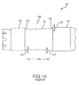
Figure 1A is a partial view of an axle, which is a prior art axle for use with the saddle of the present invention; -
Figure 1B shows interference between the inboard bearings of a wheel and an inboard transition wall of the axle ofFigure 1A ; -
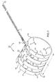
Figure 2 is a perspective view of an axle saddle system comprising a saddle and at least one strap, according to various embodiments; -
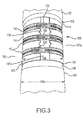
Figure 3 shows the axle saddle system ofFigure 2 covering the axle ofFigure 1A ; and -
Figure 4 is an axle method, according to various embodiments. - All ranges and ratio limits disclosed herein may be combined. It is to be understood that unless specifically stated otherwise, references to "a," "an," and/or "the" may include one or more than one and that reference to an item in the singular may also include the item in the plural.
- The detailed description of exemplary embodiments herein makes reference to the accompanying drawings, which show exemplary embodiments by way of illustration and its best mode, and not of limitation. While these exemplary embodiments are described in sufficient detail to enable those skilled in the art to practice the invention, it should be understood that other embodiments may be realized and that logical, chemical and mechanical changes may be made without departing from the spirit and scope of the invention. For example, the steps recited in any of the method or process descriptions may be executed in any order and are not necessarily limited to the order presented. Moreover, many of the functions or steps may be outsourced to or performed by one or more third parties. Furthermore, any reference to singular includes plural embodiments, and any reference to more than one component or step may include a singular embodiment or step. Also, any reference to attached, fixed, connected or the like may include permanent, removable, temporary, partial, full and/or any other possible attachment option. Additionally, any reference to without contact (or similar phrases) may also include reduced contact or minimal contact.
- In accordance with various embodiments, disclosed is an
axle saddle system 100 for anaxle 101 having an undercut between the outboard and inboard bearing lands. Theaxle saddle system 100 comprises a saddle configured to fill the axle undercut in order to protect theaxle 101 from damage by the installation of a wheel onto the axle. - According to various embodiments, and as shown in
Figure 1A ,axle 101 may be a wheel axle, and may comprise an outboard bearingland 102, an inboard bearingland 104, and anaxle shaft 106 between the outboard bearingland 102 and inboard bearingland 104. According to various embodiments, theoutboard bearing land 102, and the inboard bearingland 104, are each configured to receive abearing assembly 200 of a wheel 202 (e.g. an aircraft wheel), as shown inFigure 1B . With reference toFigure 1B , according to various embodiments, thebearing assembly 200 comprises an outboard bearing 204 configured to rotationally engage with theoutboard bearing land 102, and an inboard bearing 206 configured to rotationally engage with the inboard bearingland 104. In various embodiments, outboard bearing 204, and inboard bearing 206, may comprising, for example, tapered roller bearings. - The
axle shaft 106 is typically radially tapered with respect to at least one of theoutboard bearing land 102 and inboard bearingland 104 to form an undercut axle shaft or axle undercut 107 between the outboard bearingland 102 and inboard bearingland 104. According to various embodiments, the axle undercut 107 may be tapered with respect to both theoutboard bearing land 102, and inboard bearingland 104, with anoutboard transition wall 103 between the outboard bearingland 102 and axle undercut 107, and aninboard transition wall 105 between the inboard bearingland 104 and axle undercut 107, as shown inFigures 1A and1B . Theoutboard transition wall 103 spans radially outwards from the axle undercut 107 to theoutboard bearing land 102, and theinboard transition wall 105 spans radially outwards from the axle undercut 107 to theoutboard bearing land 102. Theoutboard transition wall 103, and theinboard transition wall 105 may each have various configurations, such as tapered, straight, etc., according to various embodiments. The axle undercut 107 can take on various configurations, such as conical, cylindrical, etc., according to various embodiments. - Due to the radial tapering of the axle undercut 107 with respect to the bearing lands, the inner diameter(s) of the outboard bearing 204 and inboard bearing 206 of
bearing assembly 200, are typically both greater than the outer diameter(s) of the axle undercut 107, according to various embodiments. This may subject theaxle 101 and bearingassembly 200 to damage, including dislodging of thebearing assembly 200, for example, during assembly, and/or removal of thewheel 202 and bearing assembly 200 (e.g. for repair, maintenance, etc.), and may make installation difficult, as the wheel may fail to translate smoothly over thebearing lands bearing assembly 200 tilts and impacts against the axle undercut 107, exerts torque against one of theoutboard bearing land 102 and/or inboard bearingland 104, impacts against one of theoutboard transition wall 103 and/orinboard transition wall 105, etc.Figure 1B shows a possible scenario wherein the inboard bearing 206 compacts against theinboard transition wall 105 of the inboard bearingland 104. - According to various embodiments,
axle saddle system 100 is configured to substantially fill the axle undercut 107, to create anaxle profile 107a, which is substantially flush or level with theoutboard bearing land 102 and inboard bearingland 104. According to various embodiments, theouter diameter 108 of the filledaxle shaft 106 may be slightly below the inner diameter(s) 108a of thebearing assembly 200. This may prevent damage to theaxle 101 and bearingassembly 200, as described above, as the substantially filled axle undercut more closely conforms to the diameter(s) 108a of thebearing assembly 200. - According to various embodiments, the
axle saddle system 100 comprises asaddle 110 and may comprise asaddle strap 112, as shown inFigure 2 . - According to various embodiments, the
saddle 110 is configured to substantially cover the axle undercut 107 over its surface area, and to substantially fill the axle undercut 107, such that the substantially filled undercut has aprofile 107a which is substantially level with theoutboard bearing land 102 and theinboard bearing land 104. - According to various embodiments,
saddle 110 is configured to conform to the geometry of the axle undercut 107. According to various embodiments, the axle undercut 107 has a circumferential perimeter, and may be cylindrical or conical (e.g., where theinboard bearing 206 has a larger diameter than the outboard bearing 204). According to various embodiments, thesaddle 110 may have anaxial length 124 approximately equal to theaxial length 124a (seeFigure 1A ) of the axle undercut 107. According to various embodiments, thesaddle 110 may wrap around a majority portion of the circumferential perimeter of the axle undercut 107. According to various embodiments, thesaddle 110 comprises afirst saddle end 114 configured to abut theoutboard transition wall 103, and asecond saddle end 116 configured to abut theinboard transition wall 105. According to various embodiments, thesaddle 110 may have athickness 118 approximately equal to or slightly less than the radial span 120 (FIG. 1A ) of theoutboard transition wall 103 and/or radial span 122 (FIG. 1A ) of theinboard transition wall 105. In various embodiments,radial span 120 may equal theradial span 122. In various embodiments,radial span 120 may not equal theradial span 122, andthickness 118 may gradually transition from a thickness approximately equal to or slightly less thanradial span 120 atfirst saddle end 114, to a thickness approximately equal to or slightly less thanradial span 122 atsecond saddle end 116, orthickness 118 may be approximately equal to or slightly less than the lesser ofradial span 120 andradial span 122, according to various embodiments. According to various embodiments,saddle 110 may be formed from a metal such as stainless steel. - According to various embodiments,
saddle 110 comprises an axial cut out portion or anaxial split 126, along theaxial length 124 of thesaddle 110, for facilitating insertion of the saddle into the axle undercut 107. According to various embodiments,axial split 126 may span between approximately 10° to 45° of the circumference of thesaddle 110. Thus, in describing thesaddle 110 as configured to substantially cover the axle undercut 107 over its surface area, the term "substantially cover" may include a coverage spanning at least 315° of the perimeter of the surface area according to various embodiments. According to various embodiments,saddle 110 may be deformed to an open position for insertion by pulling apart theedges 127 of theaxial split 126, enabling thesaddle 110 to spread open, and slip over the axle undercut 107, then spring back into its natural shape. According to various embodiments, in the open position,saddle 110 may be deformed, such that axial split is approximately equal to thediameter 108a of the bearingassembly 200. According to various embodiments,axial split 126 of thesaddle 110 in its natural shape may span approximately 45° of the perimeter of the surface area of the axle undercut 107. - According to various embodiments,
saddle 110 ofaxle saddle system 100 is tightened around axle undercut 107 viasaddle strap 112. According to various embodiments,saddle strap 112 comprises abuckle 128 andstrap end 129. According to various embodiments,saddle strap 112 may be a band clamp or cable tie, or other similar closure device having low strap and buckle profiles. According to various embodiments thesaddle strap 112 may be a stainless steel cable tie. Example of suitable saddle straps 112 having a low profile, flat head buckle (e.g. pawl and ratchet locking mechanism) may include various cable ties manufactured by Thomas and Betts and sold under the tradename TY RAP® or TY-MET®. According to various embodiments,saddle strap 112 may be installed by pulling thestrap end 129 throughbuckle 128 to tighten its hold of thesaddle 110 around the axle undercut 107. According to various embodiments, an excess end portion ofsaddle strap 112 may be broken off after tightening (e.g by twisting the end of thesaddle strap 112, whereinsaddle strap 112 is metallic). - According to various embodiments,
saddle 110 comprises astrap channel 130 and a buckle cut out 140. According to various embodiments,saddle strap 112 is configured to nest within thestrap channel 130, and buckle 128 is configured to nest within the buckle cut out 140 adjacent to thestrap channel 130. According to various embodiments,strap channel 130 forms a circumferential recess insaddle 110, and the buckle cut out 140 is an extension ofaxial split 126, as shown inFigure 2 . According to various embodiments, the thickness ofsaddle strap 112 and buckle 128 are less than thethickness 118 of thesaddle 110, such thatsaddle strap 112 andbuckle 128, situated withinstrap channel 130 and buckle cut out 140, are flush and/or recessed with respect to anouter surface 150 ofsaddle 110. - According to various embodiments,
axle saddle system 100 comprises two or more saddle straps 112, and saddle 110 comprises two ormore strap channels 130. According to various embodiments, two ormore strap channels 130 include adjacent buckle cutouts 140 for eachstrap channel 130, wherein the saddle straps 112 are configured to nest withstrap channels 130. In various embodiments, theaxle saddle system 100 comprises 3 saddle straps 112, and saddle 110 comprises 3strap channels 130 and 3 buckle cutouts 140, for the saddle straps 112. - According to various embodiments,
saddle 110 may further comprise a moisture draining system comprising drain holes 142 to prevent moisture (e.g., from condensation) from being trapped between thesaddle 110 and axle undercut 107. According to various embodiments, thesaddle 110 may comprise a plurality of spaced apart drainholes 142 throughout thesaddle 110. In various embodiments, thesaddle 110 includes 4 rows of 4 drain holes 142, for a total of 16drain holes 142 as shown inFigure 2 . - According to various embodiments, the
axle saddle system 100 may comprise any number of thestrap channels 130 and the buckle cutouts 140, the drain holes 142, different types and/or number of the saddle straps 112, including embodiments without straps, and moisture drainage systems, etc. depending on design preferences, available materials, axle design, etc. - According to various embodiments, an
axle method 400, shown inFigure 4 comprises a first step of prying a saddle open (step 401), wherein the saddle comprises an axial split which enables the saddle to be deformed open. According to various embodiments,axle method 400 further comprises a next step of inserting the saddle over an undercut of a wheel axle (step 402). According to various embodiments, the wheel axle comprises an outboard bearing land and an inboard bearing land, wherein the undercut is situated between the outboard bearing land and the inboard bearing land and is tapered with respect to at least one of the outboard bearing land and the inboard bearing land. According to various embodiments, the saddle is configured to substantially fill the undercut, such that the substantially filled undercut is substantially level with the outboard bearing land and the inboard bearing land. According to various embodiments,axle method 400 further comprises a step of tightening the saddle around the undercut (step 403). According to various embodiments, at least one saddle strap may be used to tighten the saddle around the undercut forstep 403. According to various embodiments, the saddle strap comprises a buckle and a strap end, theaxle method 400 further comprising a step of inserting the strap end through the buckle (step 405), and a step of pulling the strap end through the buckle to tighten the strap around the saddle (step 406). According to various embodiments,axle method 400 may further comprise a step of breaking off an excess portion of the strap (step 407), which is the portion of the strap adjacent the strap end which was pulled through the buckle instep 406. According to various embodiments, the saddle may be left installed on the undercut, for example, after installation of a wheel. According to various embodiments, the saddle may be removed after the wheel has been installed. - Systems and methods are provided. In the detailed description herein, references to "various embodiments", "one embodiment", "an embodiment", "an example embodiment", etc., indicate that the embodiment described may include a particular feature, structure, or characteristic, but every embodiment may not necessarily include the particular feature, structure, or characteristic. Moreover, such phrases are not necessarily referring to the same embodiment. Further, when a particular feature, structure, or characteristic is described in connection with an embodiment, it is submitted that it is within the knowledge of one skilled in the art to affect such feature, structure, or characteristic in connection with other embodiments whether or not explicitly described. After reading the description, it will be apparent to one skilled in the relevant art(s) how to implement the disclosure in alternative embodiments.
- Benefits, other advantages, and solutions to problems have been described herein with regard to specific embodiments. However, the benefits, advantages, solutions to problems, and any elements that may cause any benefit, advantage, or solution to occur or become more pronounced are not to be construed as critical, required, or essential features or elements of the invention. The scope of the invention is accordingly to be limited by nothing other than the appended claims, in which reference to an element in the singular is not intended to mean "one and only one" unless explicitly so stated, but rather "one or more." Moreover, where a phrase similar to "at least one of A, B, or C" is used in the claims, it is intended that the phrase be interpreted to mean that A alone may be present in an embodiment, B alone may be present in an embodiment, C alone may be present in an embodiment, or that any combination of the elements A, B and C may be present in a single embodiment; for example, A and B, A and C, B and C, or A and B and C. Furthermore, no element, component, or method step in the present disclosure is intended to be dedicated to the public regardless of whether the element, component, or method step is explicitly recited in the claims. No claim element herein is to be construed under the provisions of 35 U.S.C. 112(f) unless the element is expressly recited using the phrase "means for." As used herein, the terms "comprises", "comprising", or any other variation thereof, are intended to cover a non-exclusive inclusion, such that a process, method, article, or apparatus that comprises a list of elements does not include only those elements but may include other elements not expressly listed or inherent to such process, method, article, or apparatus.
Claims (15)
- An axle saddle system comprising:a saddle (110) configured to substantially cover an undercut (107) of an axle over a surface area of the undercut (107); andat least one saddle strap (112) configured to tighten the saddle around the undercut,wherein the axle comprises an outboard bearing land and an inboard bearing land,wherein the undercut (107) is situated between the outboard bearing land and the inboard bearing land,wherein the undercut (107) comprises an undercut perimeter and an undercut axial length,wherein the undercut (107) is radially tapered with respect to at least one of the outboard bearing land and the inboard bearing land, andwherein the saddle (110) is configured to substantially fill the undercut (107), such that the substantially filled undercut (107) has a profile which is substantially level with the outboard bearing land and the inboard bearing land.
- The axle saddle system of claim 1, wherein the saddle (110) has a saddle axial length approximately equal to the undercut axial length.
- The axle saddle system of claim 2, the saddle (110) comprising a strap channel (130), wherein the at least one saddle strap (112) is configured to nest within the strap channel (130).
- The axle saddle system of claim 3, the saddle strap (112) comprising a buckle (128), the saddle (110) comprising a buckle cut out (140) adjacent the strap channel, wherein the buckle (128) is configured to nest within the buckle cut out (140).
- The axle saddle system of claim 4, the saddle comprising an outer surface, wherein the saddle strap (112) and the buckle (128) are substantially level with the outer surface when nested, or the axle saddle system comprising three saddle straps (112), and the saddle comprising three strap channels (130) and three buckle cut outs (140).
- The axle saddle system of claim 2, wherein the at least one saddle strap (112) is a stainless steel cable tie.
- The axle saddle system of any preceding claim, wherein the saddle (110) further comprises a moisture draining system, and preferably wherein the moisture draining system comprises a plurality of drain holes in the saddle (110).
- The axle saddle system of any preceding claim, the saddle (110) comprising at least one of a cylindrical or a conical geometry.
- The axle saddle system of claim 1, the saddle (110) having a saddle perimeter and an axial split along the saddle axial length, the axial split spanning between approximately 10° to 45° of the saddle perimeter, and preferably wherein the saddle (110) may be deformed to an open position for insertion over the undercut (107).
- The axle saddle system of any preceding claim, wherein the outboard bearing land and the inboard bearing land are each configured to receive a bearing assembly of an aircraft wheel, and/or wherein the undercut (107) is tapered with respect to both the outboard bearing land and the inboard bearing land.
- An axle method comprising:inserting a saddle (110) over an undercut (107) of an axle, andtightening the saddle (110) around the undercut (107),wherein the axle comprises an outboard bearing land and an inboard bearing land,wherein the undercut (107) is situated between the outboard bearing land and the inboard bearing land and is radially tapered with respect to at least one of the outboard bearing land and the inboard bearing land, andwherein the saddle (110) is configured to substantially fill the undercut (107) over a surface area of the undercut (107), such that the substantially filled undercut (107) is substantially level with the outboard bearing land and the inboard bearing land,wherein the undercut (107) comprises an undercut perimeter and an undercut axial length forming the surface area of the undercut (107), andwherein the saddle (110) has a saddle axial length approximately equal to the undercut axial length.
- The axle method of claim 11, further comprising tightening the saddle (110) around the undercut (107) with at least one saddle strap (112).
- The axle method of claim 12, further comprising deforming the saddle open before inserting, and/or the saddle strap (112) comprising a buckle (128) and a strap end, the axle saddle method further comprising inserting the strap end through the buckle (128), pulling the strap end to tighten the saddle strap (112) around the saddle (110), and breaking off an excess portion of the saddle strap (112).
- An axle saddle system, comprising:a saddle (110) configured to substantially cover an undercut (107) of an axle over a surface area of the undercut (107), anda saddle strap (112) configured to tighten the saddle (110) around the undercut (107),wherein the undercut (107) is situated between an outboard bearing land and an inboard bearing land of the axle,wherein the undercut (107) is radially tapered with respect to the outboard bearing land and the inboard bearing land,wherein the undercut (107) comprises an undercut perimeter and an undercut axial length forming the surface area of the undercut (107),wherein the saddle (110) has a saddle axial length approximately equal to the undercut axial length, and a saddle perimeter configured to span at least 315 degrees of the undercut perimeter,wherein the saddle (110) is configured to substantially fill the undercut (107), such that the substantially filled undercut (107) has a profile which is substantially level with the outboard bearing land and the inboard bearing land,wherein the saddle (110) comprises a strap channel (130), andwherein the saddle strap (112) is configured to nest within the strap channel (130).
- The axle saddle system of claim 14, wherein the saddle (110) and saddle strap (112) are metallic.
Applications Claiming Priority (1)
| Application Number | Priority Date | Filing Date | Title |
|---|---|---|---|
| US14/874,098 US10329011B2 (en) | 2015-10-02 | 2015-10-02 | Axle saddle |
Publications (2)
| Publication Number | Publication Date |
|---|---|
| EP3150487A1 true EP3150487A1 (en) | 2017-04-05 |
| EP3150487B1 EP3150487B1 (en) | 2018-11-21 |
Family
ID=57083155
Family Applications (1)
| Application Number | Title | Priority Date | Filing Date |
|---|---|---|---|
| EP16191533.5A Not-in-force EP3150487B1 (en) | 2015-10-02 | 2016-09-29 | Axle saddle |
Country Status (2)
| Country | Link |
|---|---|
| US (2) | US10329011B2 (en) |
| EP (1) | EP3150487B1 (en) |
Families Citing this family (1)
| Publication number | Priority date | Publication date | Assignee | Title |
|---|---|---|---|---|
| FR3037914B1 (en) * | 2015-06-23 | 2017-08-11 | Alstom Transp Tech | AXLE COMPRISING AT LEAST TWO PROTECTIVE DEVICES |
Citations (2)
| Publication number | Priority date | Publication date | Assignee | Title |
|---|---|---|---|---|
| US3707270A (en) * | 1970-11-30 | 1972-12-26 | Blh Electronics | Wear sleeve-transducer combination for aircraft landing gear |
| US20160297516A1 (en) * | 2015-04-10 | 2016-10-13 | Goodrich Corporation | Axle sleeve |
Family Cites Families (23)
| Publication number | Priority date | Publication date | Assignee | Title |
|---|---|---|---|---|
| US2435048A (en) * | 1946-05-02 | 1948-01-27 | J H Weatherford | Antiground-loop brake |
| US4433765A (en) * | 1982-09-13 | 1984-02-28 | General Clutch Corp. | Spring clutches |
| US4772139A (en) * | 1987-09-23 | 1988-09-20 | Bretton Kenneth M | Liner for bearing assemblies and the like |
| US5020832A (en) | 1990-04-04 | 1991-06-04 | General Engineering Company | Flexible pipe saddle |
| US5360241A (en) | 1991-08-07 | 1994-11-01 | Npc, Inc. | Universal saddle tee for pipes |
| US5995202A (en) * | 1995-03-03 | 1999-11-30 | Fuji Photo Film Co., Ltd. | Method and apparatus for producing index prints and density adjusting method |
| US5695202A (en) * | 1996-09-27 | 1997-12-09 | Trw Inc. | Flexible boot for enclosing a universal joint |
| US6139027A (en) * | 1998-01-05 | 2000-10-31 | Biekx; Ron O. | CV joint boot with sealing sleeves |
| JPH11198887A (en) * | 1998-01-13 | 1999-07-27 | Honda Motor Co Ltd | Axle fixing device |
| US6412803B1 (en) * | 2001-05-04 | 2002-07-02 | Answer Products, Inc. | Front fork for cycles |
| CA2452908C (en) * | 2002-03-20 | 2008-05-20 | Rollease, Inc. | A roller shade clutch with internal gearing |
| GB2392140B (en) * | 2002-08-23 | 2004-06-30 | Kenneth William Baldwin | Cycle wheel mounting components thereof and cycle including wheel mounting |
| US7409749B2 (en) * | 2003-03-06 | 2008-08-12 | Panduit Corp. | Coated stainless steel cable tie |
| JP2004340242A (en) * | 2003-05-15 | 2004-12-02 | Ntn Corp | Tapered roller bearing device for wheel |
| US7090308B2 (en) * | 2003-11-24 | 2006-08-15 | Sram Corporation | Axle assembly for mounting a wheel to a vehicle |
| DE10359645B4 (en) * | 2003-12-18 | 2015-02-05 | Schaeffler Technologies Gmbh & Co. Kg | Wheel bearing module in a wheel carrier |
| US20080191545A1 (en) * | 2007-02-13 | 2008-08-14 | Fox Factory, Inc. | Axles, Such as for Bicycles |
| JP2008284919A (en) * | 2007-05-15 | 2008-11-27 | Ntn Corp | Bearing device for wheel, method of assembling bearing device for wheel, assembly body, and method of assembling assembly body |
| US20120031516A1 (en) | 2010-06-18 | 2012-02-09 | National Machine Company | Axle Sleeve Manufacturing Process |
| US10189305B2 (en) * | 2011-08-29 | 2019-01-29 | Sram, Llc | Bicycle front wheel hub with torque tube |
| WO2016080959A1 (en) * | 2014-11-18 | 2016-05-26 | Compagnie Generale Des Etablissements Michelin | Spindle system for wheel alignment correction |
| US20160236511A1 (en) * | 2015-02-13 | 2016-08-18 | Kic Llc | Extended length bearing cone system |
| US10041544B2 (en) * | 2015-11-20 | 2018-08-07 | Honda Patents & Technologies North America, Llc | Preloading axle clamp for a landing gear wheel bearing and a method of controlling a preloading force on a landing gear wheel bearing |
-
2015
- 2015-10-02 US US14/874,098 patent/US10329011B2/en not_active Expired - Fee Related
-
2016
- 2016-09-29 EP EP16191533.5A patent/EP3150487B1/en not_active Not-in-force
-
2019
- 2019-05-16 US US16/413,962 patent/US10787248B2/en not_active Expired - Fee Related
Patent Citations (2)
| Publication number | Priority date | Publication date | Assignee | Title |
|---|---|---|---|---|
| US3707270A (en) * | 1970-11-30 | 1972-12-26 | Blh Electronics | Wear sleeve-transducer combination for aircraft landing gear |
| US20160297516A1 (en) * | 2015-04-10 | 2016-10-13 | Goodrich Corporation | Axle sleeve |
Also Published As
| Publication number | Publication date |
|---|---|
| US10329011B2 (en) | 2019-06-25 |
| US20190270514A1 (en) | 2019-09-05 |
| US10787248B2 (en) | 2020-09-29 |
| US20170096216A1 (en) | 2017-04-06 |
| EP3150487B1 (en) | 2018-11-21 |
Similar Documents
| Publication | Publication Date | Title |
|---|---|---|
| US12253198B2 (en) | Insert for mounting multiple cables in cable hanger | |
| EP3146122B1 (en) | Cap for anchor of post-tension anchorage system | |
| US10787248B2 (en) | Axle saddle | |
| CN112228434A (en) | Clamping collar with fixing fingers | |
| WO2018229445A1 (en) | Positive locking fastener | |
| EP3159179A2 (en) | Mismatch side rim and lock ring interface angles for lock ring wheel | |
| WO2004088153A1 (en) | A fastening | |
| US20160201834A1 (en) | Hose clamp | |
| US9956817B2 (en) | Wheel assembly tie bolt retention system | |
| EP3324059B1 (en) | Nut retention system | |
| WO2020146201A1 (en) | Cushion sleeve | |
| KR101494722B1 (en) | Anchor for construction lift and method for assembling the same | |
| US20060043692A1 (en) | Crimp-ring for stabilizer bar | |
| US6932389B2 (en) | Connector with fluid line installation indicator | |
| US10982707B2 (en) | Tie bolt retention | |
| EP3715244B1 (en) | Bolted joint for wheel assemblies | |
| EP3587140B1 (en) | Torque bar retention for wheel assemblies | |
| WO2017102265A1 (en) | Clamping joint for an anchoring wire | |
| WO2007049969A1 (en) | Extraction means for a connector element of a coupling and protection means for the connector element | |
| JP3831817B2 (en) | Rust prevention coated PC steel edge fixing method | |
| AU2006200094A1 (en) | Cable bolt | |
| WO2024115217A1 (en) | Support for cable harness rails | |
| US20170022695A1 (en) | Toilet installation system and method of installing toilet | |
| WO2018058156A2 (en) | Tension limiting rock anchor | |
| JPH10281358A (en) | Forming method of the projection of the tube opening |
Legal Events
| Date | Code | Title | Description |
|---|---|---|---|
| PUAI | Public reference made under article 153(3) epc to a published international application that has entered the european phase |
Free format text: ORIGINAL CODE: 0009012 |
|
| STAA | Information on the status of an ep patent application or granted ep patent |
Free format text: STATUS: THE APPLICATION HAS BEEN PUBLISHED |
|
| AK | Designated contracting states |
Kind code of ref document: A1 Designated state(s): AL AT BE BG CH CY CZ DE DK EE ES FI FR GB GR HR HU IE IS IT LI LT LU LV MC MK MT NL NO PL PT RO RS SE SI SK SM TR |
|
| AX | Request for extension of the european patent |
Extension state: BA ME |
|
| STAA | Information on the status of an ep patent application or granted ep patent |
Free format text: STATUS: REQUEST FOR EXAMINATION WAS MADE |
|
| 17P | Request for examination filed |
Effective date: 20171005 |
|
| RBV | Designated contracting states (corrected) |
Designated state(s): AL AT BE BG CH CY CZ DE DK EE ES FI FR GB GR HR HU IE IS IT LI LT LU LV MC MK MT NL NO PL PT RO RS SE SI SK SM TR |
|
| GRAP | Despatch of communication of intention to grant a patent |
Free format text: ORIGINAL CODE: EPIDOSNIGR1 |
|
| STAA | Information on the status of an ep patent application or granted ep patent |
Free format text: STATUS: GRANT OF PATENT IS INTENDED |
|
| RIC1 | Information provided on ipc code assigned before grant |
Ipc: B64C 25/36 20060101AFI20180427BHEP |
|
| INTG | Intention to grant announced |
Effective date: 20180605 |
|
| RIN1 | Information on inventor provided before grant (corrected) |
Inventor name: PATTERSON, MICHAEL NEAL Inventor name: KOSSLER, JOSHUA STEPHEN Inventor name: SWANK, JOHN Inventor name: HUNNICUTT, SHANE E. |
|
| GRAS | Grant fee paid |
Free format text: ORIGINAL CODE: EPIDOSNIGR3 |
|
| GRAA | (expected) grant |
Free format text: ORIGINAL CODE: 0009210 |
|
| STAA | Information on the status of an ep patent application or granted ep patent |
Free format text: STATUS: THE PATENT HAS BEEN GRANTED |
|
| AK | Designated contracting states |
Kind code of ref document: B1 Designated state(s): AL AT BE BG CH CY CZ DE DK EE ES FI FR GB GR HR HU IE IS IT LI LT LU LV MC MK MT NL NO PL PT RO RS SE SI SK SM TR |
|
| REG | Reference to a national code |
Ref country code: CH Ref legal event code: EP |
|
| REG | Reference to a national code |
Ref country code: IE Ref legal event code: FG4D |
|
| REG | Reference to a national code |
Ref country code: DE Ref legal event code: R096 Ref document number: 602016007361 Country of ref document: DE |
|
| REG | Reference to a national code |
Ref country code: AT Ref legal event code: REF Ref document number: 1067243 Country of ref document: AT Kind code of ref document: T Effective date: 20181215 |
|
| REG | Reference to a national code |
Ref country code: NL Ref legal event code: MP Effective date: 20181121 |
|
| REG | Reference to a national code |
Ref country code: AT Ref legal event code: MK05 Ref document number: 1067243 Country of ref document: AT Kind code of ref document: T Effective date: 20181121 |
|
| PG25 | Lapsed in a contracting state [announced via postgrant information from national office to epo] |
Ref country code: ES Free format text: LAPSE BECAUSE OF FAILURE TO SUBMIT A TRANSLATION OF THE DESCRIPTION OR TO PAY THE FEE WITHIN THE PRESCRIBED TIME-LIMIT Effective date: 20181121 Ref country code: AT Free format text: LAPSE BECAUSE OF FAILURE TO SUBMIT A TRANSLATION OF THE DESCRIPTION OR TO PAY THE FEE WITHIN THE PRESCRIBED TIME-LIMIT Effective date: 20181121 Ref country code: NO Free format text: LAPSE BECAUSE OF FAILURE TO SUBMIT A TRANSLATION OF THE DESCRIPTION OR TO PAY THE FEE WITHIN THE PRESCRIBED TIME-LIMIT Effective date: 20190221 Ref country code: FI Free format text: LAPSE BECAUSE OF FAILURE TO SUBMIT A TRANSLATION OF THE DESCRIPTION OR TO PAY THE FEE WITHIN THE PRESCRIBED TIME-LIMIT Effective date: 20181121 Ref country code: IS Free format text: LAPSE BECAUSE OF FAILURE TO SUBMIT A TRANSLATION OF THE DESCRIPTION OR TO PAY THE FEE WITHIN THE PRESCRIBED TIME-LIMIT Effective date: 20190321 Ref country code: BG Free format text: LAPSE BECAUSE OF FAILURE TO SUBMIT A TRANSLATION OF THE DESCRIPTION OR TO PAY THE FEE WITHIN THE PRESCRIBED TIME-LIMIT Effective date: 20190221 Ref country code: LT Free format text: LAPSE BECAUSE OF FAILURE TO SUBMIT A TRANSLATION OF THE DESCRIPTION OR TO PAY THE FEE WITHIN THE PRESCRIBED TIME-LIMIT Effective date: 20181121 Ref country code: HR Free format text: LAPSE BECAUSE OF FAILURE TO SUBMIT A TRANSLATION OF THE DESCRIPTION OR TO PAY THE FEE WITHIN THE PRESCRIBED TIME-LIMIT Effective date: 20181121 Ref country code: LV Free format text: LAPSE BECAUSE OF FAILURE TO SUBMIT A TRANSLATION OF THE DESCRIPTION OR TO PAY THE FEE WITHIN THE PRESCRIBED TIME-LIMIT Effective date: 20181121 |
|
| PG25 | Lapsed in a contracting state [announced via postgrant information from national office to epo] |
Ref country code: NL Free format text: LAPSE BECAUSE OF FAILURE TO SUBMIT A TRANSLATION OF THE DESCRIPTION OR TO PAY THE FEE WITHIN THE PRESCRIBED TIME-LIMIT Effective date: 20181121 Ref country code: RS Free format text: LAPSE BECAUSE OF FAILURE TO SUBMIT A TRANSLATION OF THE DESCRIPTION OR TO PAY THE FEE WITHIN THE PRESCRIBED TIME-LIMIT Effective date: 20181121 Ref country code: SE Free format text: LAPSE BECAUSE OF FAILURE TO SUBMIT A TRANSLATION OF THE DESCRIPTION OR TO PAY THE FEE WITHIN THE PRESCRIBED TIME-LIMIT Effective date: 20181121 Ref country code: AL Free format text: LAPSE BECAUSE OF FAILURE TO SUBMIT A TRANSLATION OF THE DESCRIPTION OR TO PAY THE FEE WITHIN THE PRESCRIBED TIME-LIMIT Effective date: 20181121 Ref country code: PT Free format text: LAPSE BECAUSE OF FAILURE TO SUBMIT A TRANSLATION OF THE DESCRIPTION OR TO PAY THE FEE WITHIN THE PRESCRIBED TIME-LIMIT Effective date: 20190321 Ref country code: GR Free format text: LAPSE BECAUSE OF FAILURE TO SUBMIT A TRANSLATION OF THE DESCRIPTION OR TO PAY THE FEE WITHIN THE PRESCRIBED TIME-LIMIT Effective date: 20190222 |
|
| PG25 | Lapsed in a contracting state [announced via postgrant information from national office to epo] |
Ref country code: DK Free format text: LAPSE BECAUSE OF FAILURE TO SUBMIT A TRANSLATION OF THE DESCRIPTION OR TO PAY THE FEE WITHIN THE PRESCRIBED TIME-LIMIT Effective date: 20181121 Ref country code: PL Free format text: LAPSE BECAUSE OF FAILURE TO SUBMIT A TRANSLATION OF THE DESCRIPTION OR TO PAY THE FEE WITHIN THE PRESCRIBED TIME-LIMIT Effective date: 20181121 Ref country code: CZ Free format text: LAPSE BECAUSE OF FAILURE TO SUBMIT A TRANSLATION OF THE DESCRIPTION OR TO PAY THE FEE WITHIN THE PRESCRIBED TIME-LIMIT Effective date: 20181121 Ref country code: IT Free format text: LAPSE BECAUSE OF FAILURE TO SUBMIT A TRANSLATION OF THE DESCRIPTION OR TO PAY THE FEE WITHIN THE PRESCRIBED TIME-LIMIT Effective date: 20181121 |
|
| REG | Reference to a national code |
Ref country code: DE Ref legal event code: R097 Ref document number: 602016007361 Country of ref document: DE |
|
| PG25 | Lapsed in a contracting state [announced via postgrant information from national office to epo] |
Ref country code: SK Free format text: LAPSE BECAUSE OF FAILURE TO SUBMIT A TRANSLATION OF THE DESCRIPTION OR TO PAY THE FEE WITHIN THE PRESCRIBED TIME-LIMIT Effective date: 20181121 Ref country code: RO Free format text: LAPSE BECAUSE OF FAILURE TO SUBMIT A TRANSLATION OF THE DESCRIPTION OR TO PAY THE FEE WITHIN THE PRESCRIBED TIME-LIMIT Effective date: 20181121 Ref country code: EE Free format text: LAPSE BECAUSE OF FAILURE TO SUBMIT A TRANSLATION OF THE DESCRIPTION OR TO PAY THE FEE WITHIN THE PRESCRIBED TIME-LIMIT Effective date: 20181121 Ref country code: SM Free format text: LAPSE BECAUSE OF FAILURE TO SUBMIT A TRANSLATION OF THE DESCRIPTION OR TO PAY THE FEE WITHIN THE PRESCRIBED TIME-LIMIT Effective date: 20181121 |
|
| PLBE | No opposition filed within time limit |
Free format text: ORIGINAL CODE: 0009261 |
|
| STAA | Information on the status of an ep patent application or granted ep patent |
Free format text: STATUS: NO OPPOSITION FILED WITHIN TIME LIMIT |
|
| 26N | No opposition filed |
Effective date: 20190822 |
|
| PG25 | Lapsed in a contracting state [announced via postgrant information from national office to epo] |
Ref country code: SI Free format text: LAPSE BECAUSE OF FAILURE TO SUBMIT A TRANSLATION OF THE DESCRIPTION OR TO PAY THE FEE WITHIN THE PRESCRIBED TIME-LIMIT Effective date: 20181121 |
|
| PG25 | Lapsed in a contracting state [announced via postgrant information from national office to epo] |
Ref country code: TR Free format text: LAPSE BECAUSE OF FAILURE TO SUBMIT A TRANSLATION OF THE DESCRIPTION OR TO PAY THE FEE WITHIN THE PRESCRIBED TIME-LIMIT Effective date: 20181121 |
|
| REG | Reference to a national code |
Ref country code: DE Ref legal event code: R119 Ref document number: 602016007361 Country of ref document: DE |
|
| PG25 | Lapsed in a contracting state [announced via postgrant information from national office to epo] |
Ref country code: MC Free format text: LAPSE BECAUSE OF FAILURE TO SUBMIT A TRANSLATION OF THE DESCRIPTION OR TO PAY THE FEE WITHIN THE PRESCRIBED TIME-LIMIT Effective date: 20181121 |
|
| REG | Reference to a national code |
Ref country code: CH Ref legal event code: PL |
|
| PG25 | Lapsed in a contracting state [announced via postgrant information from national office to epo] |
Ref country code: DE Free format text: LAPSE BECAUSE OF NON-PAYMENT OF DUE FEES Effective date: 20200401 Ref country code: LU Free format text: LAPSE BECAUSE OF NON-PAYMENT OF DUE FEES Effective date: 20190929 Ref country code: LI Free format text: LAPSE BECAUSE OF NON-PAYMENT OF DUE FEES Effective date: 20190930 Ref country code: CH Free format text: LAPSE BECAUSE OF NON-PAYMENT OF DUE FEES Effective date: 20190930 Ref country code: IE Free format text: LAPSE BECAUSE OF NON-PAYMENT OF DUE FEES Effective date: 20190929 |
|
| REG | Reference to a national code |
Ref country code: BE Ref legal event code: MM Effective date: 20190930 |
|
| PG25 | Lapsed in a contracting state [announced via postgrant information from national office to epo] |
Ref country code: BE Free format text: LAPSE BECAUSE OF NON-PAYMENT OF DUE FEES Effective date: 20190930 |
|
| PG25 | Lapsed in a contracting state [announced via postgrant information from national office to epo] |
Ref country code: CY Free format text: LAPSE BECAUSE OF FAILURE TO SUBMIT A TRANSLATION OF THE DESCRIPTION OR TO PAY THE FEE WITHIN THE PRESCRIBED TIME-LIMIT Effective date: 20181121 |
|
| PG25 | Lapsed in a contracting state [announced via postgrant information from national office to epo] |
Ref country code: HU Free format text: LAPSE BECAUSE OF FAILURE TO SUBMIT A TRANSLATION OF THE DESCRIPTION OR TO PAY THE FEE WITHIN THE PRESCRIBED TIME-LIMIT; INVALID AB INITIO Effective date: 20160929 Ref country code: MT Free format text: LAPSE BECAUSE OF FAILURE TO SUBMIT A TRANSLATION OF THE DESCRIPTION OR TO PAY THE FEE WITHIN THE PRESCRIBED TIME-LIMIT Effective date: 20181121 |
|
| PGFP | Annual fee paid to national office [announced via postgrant information from national office to epo] |
Ref country code: FR Payment date: 20210819 Year of fee payment: 6 |
|
| PGFP | Annual fee paid to national office [announced via postgrant information from national office to epo] |
Ref country code: GB Payment date: 20210820 Year of fee payment: 6 |
|
| PG25 | Lapsed in a contracting state [announced via postgrant information from national office to epo] |
Ref country code: MK Free format text: LAPSE BECAUSE OF FAILURE TO SUBMIT A TRANSLATION OF THE DESCRIPTION OR TO PAY THE FEE WITHIN THE PRESCRIBED TIME-LIMIT Effective date: 20181121 |
|
| GBPC | Gb: european patent ceased through non-payment of renewal fee |
Effective date: 20220929 |
|
| PG25 | Lapsed in a contracting state [announced via postgrant information from national office to epo] |
Ref country code: FR Free format text: LAPSE BECAUSE OF NON-PAYMENT OF DUE FEES Effective date: 20220930 |
|
| PG25 | Lapsed in a contracting state [announced via postgrant information from national office to epo] |
Ref country code: GB Free format text: LAPSE BECAUSE OF NON-PAYMENT OF DUE FEES Effective date: 20220929 |