EP3150391A2 - Printing apparatus - Google Patents
Printing apparatus Download PDFInfo
- Publication number
- EP3150391A2 EP3150391A2 EP16187615.6A EP16187615A EP3150391A2 EP 3150391 A2 EP3150391 A2 EP 3150391A2 EP 16187615 A EP16187615 A EP 16187615A EP 3150391 A2 EP3150391 A2 EP 3150391A2
- Authority
- EP
- European Patent Office
- Prior art keywords
- roller
- belt
- endless belt
- recording medium
- section
- Prior art date
- Legal status (The legal status is an assumption and is not a legal conclusion. Google has not performed a legal analysis and makes no representation as to the accuracy of the status listed.)
- Granted
Links
Images




Classifications
-
- B—PERFORMING OPERATIONS; TRANSPORTING
- B41—PRINTING; LINING MACHINES; TYPEWRITERS; STAMPS
- B41J—TYPEWRITERS; SELECTIVE PRINTING MECHANISMS, i.e. MECHANISMS PRINTING OTHERWISE THAN FROM A FORME; CORRECTION OF TYPOGRAPHICAL ERRORS
- B41J11/00—Devices or arrangements of selective printing mechanisms, e.g. ink-jet printers or thermal printers, for supporting or handling copy material in sheet or web form
- B41J11/007—Conveyor belts or like feeding devices
-
- B—PERFORMING OPERATIONS; TRANSPORTING
- B41—PRINTING; LINING MACHINES; TYPEWRITERS; STAMPS
- B41J—TYPEWRITERS; SELECTIVE PRINTING MECHANISMS, i.e. MECHANISMS PRINTING OTHERWISE THAN FROM A FORME; CORRECTION OF TYPOGRAPHICAL ERRORS
- B41J11/00—Devices or arrangements of selective printing mechanisms, e.g. ink-jet printers or thermal printers, for supporting or handling copy material in sheet or web form
- B41J11/36—Blanking or long feeds; Feeding to a particular line, e.g. by rotation of platen or feed roller
- B41J11/42—Controlling printing material conveyance for accurate alignment of the printing material with the printhead; Print registering
-
- B—PERFORMING OPERATIONS; TRANSPORTING
- B41—PRINTING; LINING MACHINES; TYPEWRITERS; STAMPS
- B41J—TYPEWRITERS; SELECTIVE PRINTING MECHANISMS, i.e. MECHANISMS PRINTING OTHERWISE THAN FROM A FORME; CORRECTION OF TYPOGRAPHICAL ERRORS
- B41J3/00—Typewriters or selective printing or marking mechanisms characterised by the purpose for which they are constructed
- B41J3/407—Typewriters or selective printing or marking mechanisms characterised by the purpose for which they are constructed for marking on special material
- B41J3/4078—Printing on textile
Definitions
- the present invention relates to a printing apparatus.
- an ink jet type printing apparatus that performs printing of patterns, or the like, on a fabric by discharging an ink toward an outer surface of the fabric, has been used in textile printing on fabrics such as cotton, silk, wool, chemical fibers, and blended fabrics.
- a printing apparatus that is used in textile printing moves a recording medium by mounting the recording medium on an endless belt having a sticky property.
- an error in the movement amount of the endless belt occurs due to variations in the dimensions in the thickness direction of the endless belt. Therefore, for example, Japanese Patent No.
- 5332884 discloses an ink jet recording apparatus (a printing apparatus) that corrects a feeding amount of an endless belt by determining a corrected feeding amount that depends on a feeding position of a transport belt (the endless belt) using a test print. As a result of this, it is stated that it is possible to control fluctuations in the feeding amount caused by the thickness of a joining section of the endless belt.
- a movement error amount of an endless belt differs depending on various printing conditions that are stipulated at a time of printing such as decentering of a belt driving roller that moves the endless belt, the type of recording medium, and the like.
- the printing apparatus that is disclosed in Japanese Patent No. 5332884 is not provided with a unit that corrects movement error of the endless belt caused by factors other than variations in the thickness of the endless belt.
- a printing apparatus including a driving roller, an endless belt that transports a recording medium using rotation of the driving roller, a roller correction table acquisition unit that acquires a roller correction table, which represents a relationship between a point of origin position of the driving roller and a movement error of the endless belt, a belt correction table acquisition unit that acquires a belt correction table, which represents a relationship between a point of origin position of the endless belt and a movement error of the endless belt, and a control section that controls driving of the driving roller by calculating a rotation amount of the driving roller on the basis of the roller correction table and the belt correction table.
- the printing apparatus includes the roller correction table acquisition unit that acquires a roller correction table, which represents a relationship between a point of origin position of the driving roller and a movement error of the endless belt.
- the printing apparatus includes a unit that determines a movement error of the endless belt caused by decentering of the driving roller.
- the printing apparatus includes a belt correction table acquisition unit that acquires a belt correction table, which represents a relationship between a point of origin position of the endless belt and a movement error of the endless belt.
- the printing apparatus includes a unit that determines a movement error of the endless belt caused by the thickness of the endless belt.
- control section of the printing apparatus drives the driving roller by calculating a rotation amount of the driving roller on the basis of the roller correction table and the belt correction table, a movement error of the endless belt caused by decentering of the driving roller is corrected in addition to variations in the thickness of the endless belt.
- the movement accuracy of the endless belt and the transport accuracy of a recording medium, which is mounted on the endless belt are improved, it is possible to improve the printing quality of an image that is formed on the recording medium. Accordingly, it is possible to provide a printing apparatus in which the transport accuracy of a recording medium is improved and the printing quality of an image is improved.
- the printing apparatus further includes roller correction tables and belt correction tables that correspond to printing conditions that are stipulated at a time of printing, and that the control section selects a roller correction table and a belt correction table that match the stipulated printing conditions.
- the printing apparatus includes roller correction tables and a belt correction tables that are acquired on the basis of various printing conditions that are stipulated at the time of printing.
- the control section of the printing apparatus driving the driving roller by calculating a rotation amount of the driving roller by selecting a roller correction table and a belt correction table that match the stipulated printing conditions, it is possible to perform correction that includes a movement error of the endless belt caused by the printing conditions.
- the printing conditions include printing quality.
- the printing apparatus includes the roller correction tables and a belt correction tables that are acquired on the basis of a printing quality that is stipulated at the time of printing.
- a mode in which printing quality is prioritized a mode in which printing velocity is prioritized, and the like, are examples of the printing quality.
- the printing velocity differs depending on the printing quality. Since a movement error of the endless belt differs depending on the printing velocity, the printing apparatus of the present application example can perform correction that includes a movement error of the endless belt caused by differences in the printing velocity, which depends on the printing quality.
- the printing conditions include a medium type of the recording medium.
- the printing apparatus includes the printing roller correction tables and a belt correction tables that are acquired on the basis of a recording medium to be used in the printing. Since a movement error of the endless belt differs depending on the stretchability, and the like, of a recording medium to be used, the printing apparatus of the present application example can perform correction that includes a movement error of the endless belt caused by the recording medium to be used.
- the printing conditions include a condition relating to a tension at a time of transporting the recording medium.
- the printing apparatus includes roller correction tables and a belt correction tables that are acquired on the basis of a condition relating to a tension that is applied when transporting the recording medium, the condition being stipulated at the time of printing.
- a "tension mode” that transports a recording medium by applying a predetermined amount of tension thereto, and a "slack mode” that reduces damage and transports a recording medium, and the like are examples of transport methods. Since the amount of a movement error of the endless belt differs depending on a transport mode of a recording medium, the printing apparatus of the present application example can perform correction that includes a movement error of the endless belt caused by the transport method of the recording medium.
- the printing apparatus further includes a tension measurement section that measures an amount of tension that is applied to the recording medium on at least one of an upstream side and a downstream side of the endless belt in a movement direction of the recording medium; and roller correction tables and belt correction tables that correspond to tension that can be measured by the tension measurement section, and that the control section selects a roller correction table and a belt correction table that match the tension that is measured by the tension measurement section.
- the printing apparatus includes the roller correction tables and a belt correction tables that are acquired on the basis of an amount of tension of the recording medium, which is measured by the tension measurement section. Since the control section selects a roller correction table and a belt correction table that match the tension that is measured by the tension measurement section, it is even possible to perform correction that includes a movement error of the endless belt caused by tension in a case in which there are fluctuations in the amount of tension of a recording medium during printing.
- an X axis, a Y axis and a Z axis are illustrated as three axes that are orthogonal to one another, a tip end side of an arrow that illustrates an axial direction is referred to as a "+ side", and a base end side thereof is referred to as a "- side".
- X axis direction a direction that is parallel to the X axis
- Y axis direction a direction that is parallel to the Y axis
- Z axis direction a direction that is parallel to the Z axis
- Fig. 1 is a schematic diagram that schematically shows an overall configuration of a printing apparatus according to Embodiment 1.
- a printing apparatus 100 is an apparatus that performs textile printing on a recording medium 95 by forming an image, or the like on the recording medium 95.
- a fabric such as cotton, wool, a chemical fiber or a blended fabric can be used as the recording medium 95.
- a configuration that forms an image on a band-like recording medium 95 using a roll method will be illustrated by way of example, but the embodiment is not limited to this configuration.
- the embodiment may use a method such as a sheet technique.
- the printing apparatus 100 includes a recording medium supply section 10, a recording medium transport section 20, a recording medium recovery section 30, a printing section 40, a cleaning unit 50, a medium adhesion section 60, a drying section 97, and the like. Further, the printing apparatus 100 includes a control section 1 that controls each of these sections. Each section of the printing apparatus 100 is attached to a frame section 92.
- the recording medium supply section 10 is a section that supplies a recording medium 95 on which an image is to be formed, to a printing section 40 side.
- the recording medium supply section 10 includes a supply shaft section 11 and a bearing section 12.
- the supply shaft section 11 is formed in a cylindrical shape or a columnar shape, and is provided so as to be rotatable in a circumferential direction.
- a band-like recording medium 95 is wound around the supply shaft section 11 in roll shape.
- the supply shaft section 11 is attached to the bearing section 12 in an attachable and detachable manner. As a result of this, a recording medium 95 in a state of being wound around the supply shaft section 11 in advance, can be attached to the supply shaft section 11 and the bearing section 12.
- the bearing section 12 supports both ends in an axial direction of the supply shaft section 11 in a rotatable manner.
- the recording medium supply section 10 includes a rotational driving section (not illustrated in the drawing) that drives the supply shaft section 11 in a rotational manner.
- the rotational driving section rotates the supply shaft section 11 in a direction in which a recording medium 95 is fed out.
- the operation of the rotational driving section is controlled by the control section 1.
- the recording medium transport section 20 is a section that transports a recording medium 95 from the recording medium supply section 10 to the recording medium recovery section 30.
- the recording medium transport section 20 includes a transport roller 21, a tension roller 22, a transport roller 23, a belt rotation roller 24, a belt driving roller 25 as a driving roller, an endless belt 26, a transport roller 27, a tension roller 28 and a transport roller 29.
- the transport rollers 21 and 23, and the tension roller 22 relay a recording medium 95 from the recording medium supply section 10 to the endless belt 26.
- the transport rollers 21 and 23 are fixed rollers that are fixed to the frame section 92, and the tension roller 22 is provided between the transport roller 21 and the transport roller 23, and is a movable roller that is movable in a vertical direction (the Z axis direction).
- the tension roller 22 is movable in a vertical direction (the Z axis direction).
- the endless belt 26 is formed in an endless shape in which both end portions of a band-like belt are connected to one another, and is hung on the belt rotation roller 24 and the belt driving roller 25.
- the endless belt 26 is maintained in a state in which a predetermined tension is applied thereto so that a portion between the belt rotation roller 24 and the belt driving roller 25 is parallel to a floor surface 99.
- a sticky layer 26c, which causes a recording medium 95 to stick to the endless belt 26, is provided on an outer surface (a support surface) 26a of the endless belt 26.
- the endless belt 26 supports (maintains) a recording medium 95, which is supplied from the transport roller 23, and is adhered to the sticky layer 26c by the medium adhesion section 60, which will be described later. As a result of this, it is possible to handle a stretchable fabric, or the like as a recording medium 95.
- the belt rotation roller 24 and the belt driving roller 25 support an inner circumferential surface 26b of the endless belt 26. Additionally, a configuration in which a support section that supports the endless belt 26, is provided between the belt rotation roller 24 and the belt driving roller 25, may also be used.
- the endless belt 26 moves a recording medium using rotation of the belt driving roller 25.
- the endless belt 26 rotates in accordance with rotation of the belt driving roller 25, and the belt rotation roller 24 rotates due to rotation of the endless belt 26.
- a recording medium 95 which is supported on the endless belt 26 is transported in a predetermined transport direction, which is illustrated by an arrow, and an image is formed on the recording medium 95 by the printing section 40, which will be described later.
- a recording medium 95 is supported on a side (a +Z axis side) on which the outer surface 26a of the endless belt 26 faces the printing section 40, and the recording medium 95 is transported from a belt rotation roller 24 side to a belt driving roller 25 side along with the endless belt 26.
- a side (a -Z axis side) on which the outer surface 26a of the endless belt 26 faces the cleaning unit 50 only the endless belt 26 moves from the belt driving roller 25 side to the belt rotation roller 24 side.
- the transport roller 27 causes a recording medium 95, on which an image is formed, to peel away from the sticky layer 26c of the endless belt 26.
- the transport rollers 27 and 29, and the tension roller 28 relay a recording medium 95 from the endless belt 26 to the recording medium recovery section 30.
- the transport rollers 27 and 29 are fixed rollers that are fixed to the frame section 92, and the tension roller 28 is provided between the transport roller 27 and the transport roller 29, and is a movable roller that is movable in the vertical direction (the Z axis direction).
- the tension roller 28 is provided between the transport roller 27 and the transport roller 29, and is a movable roller that is movable in the vertical direction (the Z axis direction).
- the recording medium recovery section 30 recovers a recording medium 95 that is transported by the recording medium transport section 20.
- the recording medium recovery section 30 includes a wind-up shaft section 31 and a bearing section 32.
- the wind-up shaft section 31 is formed in a cylindrical shape or a columnar shape, and is provided so as to be rotatable in a circumferential direction.
- a band-like recording medium 95 is wound up onto the wind-up shaft section 31 in roll shape.
- the wind-up shaft section 31 is attached to the bearing section 32 in an attachable and detachable manner. As a result of this, a recording medium 95 in a state of being wound-up onto the wind-up shaft section 31, is released along with the wind-up shaft section 31.
- the bearing section 32 supports both ends in an axial direction of the wind-up shaft section 31 in a rotatable manner.
- the recording medium recovery section 30 includes a rotational driving section (not illustrated in the drawing) that drives the wind-up shaft section 31 in a rotational manner.
- the rotational driving section rotates the wind-up shaft section 31 in a direction in which a recording medium 95 is wound up.
- the operation of the rotational driving section is controlled by the control section 1.
- a drying section 97 is disposed between the transport roller 27 and the tension roller 28.
- the drying section 97 is a section that dries an image formed on a recording medium 95.
- an IR heater in the drying section 97, and driving the IR heater, it is possible to dry an image formed on a recording medium 95 in a short period of time. As a result of this, it is possible to wind up a band-like recording medium 95 on which an image is formed, onto the wind-up shaft section 31.
- the medium adhesion section 60 is a section that causes a recording medium 95 to adhere to the endless belt 26.
- the medium adhesion section 60 is disposed further on an upstream side (a -X axis side) than the printing section 40 in the transport direction of a recording medium 95.
- the medium adhesion section 60 includes a pressing roller 61, a pressing roller driving section 62 and a roller support section 63.
- the pressing roller 61 is formed in a cylindrical shape or a columnar shape, and is provided rotatable so as to be rotatable in a circumferential direction.
- the pressing roller 61 is disposed so that an axial direction thereof intersects the transport direction in a manner in which the pressing roller 61 rotates in a direction along the transport direction.
- the roller support section 63 is provided on an inner circumferential surface 26b side of the endless belt 26, which faces the pressing roller 61 with the endless belt 26 interposed therebetween.
- the pressing roller driving section 62 moves the pressing roller 61 in the transport direction (a +X axis direction) and a direction (a -X axis direction) that is opposite to the transport direction while pressing the pressing roller 61 toward a lower side in the vertical direction (the -Z axis side).
- a recording medium 95 that is transported from the transport roller 23, and superimposed on the endless belt 26, is pressed against the endless belt 26 between the pressing roller 61 and the roller support section 63.
- the printing section 40 includes an ink jet type discharge head 42 that discharges an ink toward a recording medium 95 as liquid droplets, a carriage movement section 41 that moves a carriage 43, in which the discharge head 42 is mounted, and the like.
- the printing section 40 is disposed above a disposition position of the endless belt 26 (on the +Z axis side).
- a discharge surface 44, on which a plurality of nozzle rows 45 are formed, is provided in the discharge head 42.
- a different color of ink for example, cyan: C, magenta: M, yellow: Y and black: K
- the discharge surface 44 faces a recording medium 95 that is transported by the endless belt 26.
- the carriage movement section 41 moves the discharge head 42 in a direction that intersects the transport direction of a recording medium 95 (a width direction of a recording medium 95 (the Y axis direction)).
- the carriage 43 is supported by a guide rail (not illustrated in the drawing), which is disposed along the Y axis direction, and the carriage 43 is configured so as to be able to reciprocate in a ⁇ Y axis direction as a result of the carriage movement section 41.
- a guide rail not illustrated in the drawing
- the carriage 43 is configured so as to be able to reciprocate in a ⁇ Y axis direction as a result of the carriage movement section 41.
- a motor (not illustrated in the drawing) is provided in the carriage movement section 41 as a motive power source for moving the carriage 43 along the Y axis direction.
- the discharge head 42 reciprocates along the Y axis direction along with the carriage 43.
- a serial head type discharge head which is installed in a movable carriage and discharges an ink while moving in the width direction of a recording medium 95 (the ⁇ Y axis direction) is illustrated as the discharge head 42 by way of example, but a line head type in which the discharge head is fixedly arranged extending in the width direction of a recording medium 95 (the Y axis direction) may be used instead.
- the printing apparatus 100 is provided with the cleaning unit 50 for cleaning the endless belt 26.
- the cleaning unit 50 includes a cleaning section 51, a pressing section 52 and a movement section 53.
- the movement section 53 can be fixed in a predetermined position by moving the cleaning unit 50 along the floor surface 99 in an integral manner.
- the cleaning unit 50 is disposed between the belt rotation roller 24 and the belt driving roller 25 in the X axis direction.
- the pressing section 52 is an elevation device that is configured by an air cylinder 56 and a ball bush 57, and is capable of moving the cleaning section 51, which is provided above the pressing section 52, between a cleaning position and a retreat position.
- the cleaning position is a position in which a cleaning roller 58 and a blade 55 abut against the endless belt 26.
- the retreat position is a position in which the cleaning roller 58 and the blade 55 are separated from the endless belt 26.
- the cleaning section 51 cleans the outer surface 26a (the support surface) of the endless belt 26, which is hanging in a state in which a predetermined amount of tension is applied between the belt rotation roller 24 and the belt driving roller 25, from below (a -Z axis direction).
- Fig. 1 shows a case in which the cleaning section 51 is raised and disposed in the cleaning position.
- the cleaning section 51 includes a cleaning tub 54, the cleaning roller 58 and the blade 55.
- the cleaning tub 54 is a tub in which a cleaning solution that is used in the cleaning of ink and foreign matter that is attached to the outer surface 26a of the endless belt 26, is retained, and the cleaning roller 58 and the blade 55 are provided on an inner side of the cleaning tub 54.
- a cleaning solution that is used in the cleaning of ink and foreign matter that is attached to the outer surface 26a of the endless belt 26, is retained, and the cleaning roller 58 and the blade 55 are provided on an inner side of the cleaning tub 54.
- water a water-soluble solvent (an alcohol aqueous solution or the like), or the like
- a surfactant, an antifoaming agent, and the like may be added thereto according to necessity.
- a lower side (the -Z axis side) of the cleaning roller 58 is immersed in the cleaning solution that is retained in the cleaning tub 54.
- the cleaning roller 58 is rotated in the cleaning position, the cleaning solution is supplied to the outer surface 26a of the endless belt 26, and the cleaning roller 58 slides along the endless belt 26.
- ink and fibers or the like of a fabric of a recording medium 95, which are attached to the endless belt 26, are washed away using the cleaning roller 58.
- the blade 55 is configured by a material having a flexible property such as a silicon rubber.
- the blade 55 is provided further on a downstream side than the cleaning roller 58 in the transport direction of the endless belt 26. Cleaning solution that remains on the outer surface 26a of the endless belt 26, is removed as a result of the endless belt 26 sliding along the blade 55.
- Fig. 2 is a perspective view in which an endless belt is displayed in an enlarged manner.
- Fig. 3 is a cross-sectional view of a movement amount detection sensor.
- a movement amount detection sensor 70 and a belt point of origin sensor 80 that determine a point of origin position and a movement amount of the endless belt 26 will be described with reference to Figs. 2 and 3 .
- the belt point of origin sensor 80 is a sensor that detects a point of origin of the endless belt 26.
- markers 81 are provided at both end portions in the width direction of the endless belt 26 (the Y axis direction) on the outer surface 26a, on which the sticky layer 26c is not formed, as points of origin of the endless belt 26.
- the belt point of origin sensor 80 is provided above (in a +Z axis direction) the marker 81 in the vertical direction.
- the movement amount detection sensor 70 is a sensor that performs image process measurement of a practical (or an actual amount of movement in practice) movement amount of the endless belt 26.
- the movement amount detection sensor 70 captures images for determining a practical movement amount that the endless belt 26 moves in a practical sense through comparison of positions before movement and after movement of the endless belt 26.
- the movement amount detection sensor 70 is provided in a position that faces the printing section 40 (refer to Fig. 1 ) with the endless belt 26 interposed therebetween, and captures images of the inner circumferential surface 26b of the endless belt 26.
- the movement amount detection sensor 70 is not limited to this configuration.
- the movement amount detection sensor 70 may be provided in any position in which it is possible to capture images of the outer surface 26a, on which the sticky layer 26c of the endless belt 26 is not formed, the outer surface of a recording medium 95 that is mounted on the endless belt 26, or the like.
- it is preferable that the movement amount detection sensor 70 is provided in the vicinity of the printing section 40.
- the movement amount detection sensor 70 is provided with a light-emitting section 72, a condensing lens 73, and an image capturing element 74 on an inner side of a case 76.
- the case 76 configures the exterior of the movement amount detection sensor 70.
- the case 76 has a truncated cone shape, and a light-transmissive glass 71 is attached to a tip end portion (an upper end portion) thereof.
- the light-transmissive glass 71 faces a gap between the light-transmissive glass 71 and the inner circumferential surface 26b of the endless belt 26 in a vertical manner in a state in which a gap is interposed therebetween.
- the light-emitting section 72 is a section that radiates light toward the endless belt 26.
- the light-emitting section 72 is provided on an inner wall surface of the case 76 with an angled posture in which it is possible to emit light toward the light-transmissive glass 71.
- a light emitting diode LED
- the condensing lens 73 is a lens that condenses reflected light that passes through the light-transmissive glass 71 for a second time and is incident to the inside of the case 76 after light that is emitted from the light-emitting section 72 and passes through the light-transmissive glass 71 is reflected by the inner circumferential surface 26b of the endless belt 26, and is provided in a cylindrical portion of the case 76.
- the image capturing element 74 is an element that captures images of the inner circumferential surface 26b of the endless belt 26, which are condensed by the condensing lens 73, and includes an image capturing surface 74a in a position in which images are formed.
- the image capturing element 74 is provided on an inner bottom surface of the case 76. Additionally, the condensing lens 73 is retained at a height at which an image of the inner circumferential surface 26b of the endless belt 26 on the image capturing surface 74a of the image capturing element 74 can obtained, by a retention member 75.
- the movement amount detection sensor 70 outputs image capturing data that is captured by the image capturing element 74, to the control section 1.
- the control section 1 compares image capturing data before and after movement of the endless belt 26, and outputs a practical movement amount that the endless belt 26 has moved in a practical sense.
- a method that uses the movement amount detection sensor 70 as a measurement method of the practical movement amount of the endless belt 26, is illustrated by way of example, but the measurement method is not limited to this configuration.
- the measurement method of the practical movement amount of the endless belt 26 may be a method that uses a laser length measurement machine.
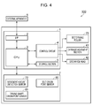
- Fig. 4 is an electrical block diagram that shows an electrical configuration of the printing apparatus. Next, the electrical configuration of the printing apparatus 100 will be described with reference to Fig. 4 .
- the control section 1 is a control unit for performing control of the printing apparatus 100.
- the control section 1 is configured to include a control circuit 4, an interface section (I/F) 2, a CPU (Central Processing Unit) 3, and a storage section 5.
- the interface section 2 is a section for performing the communication of data between an external apparatus 6, which handles images, such as a computer or a digital camera, and the printing apparatus 100.
- the CPU 3 is an arithmetic processing device for performing an input signal process from various detector groups 7 and overall control of the printing apparatus 100.
- the detector groups 7 include the movement amount detection sensor 70 for measuring the movement amount of the endless belt 26, the belt point of origin sensor 80 that detects a belt point of origin of the endless belt 26, and a driving shaft point of origin sensor 85 that detects a driving shaft point of origin of the belt driving roller 25.
- the storage section 5 is a section for securing a region that stores a program of the CPU 3, a work region, or the like, and includes storage elements such as RAM (Random Access Memory), EEPROM (Electrically Erasable Programmable Read-Only Memory), or the like.
- RAM Random Access Memory
- EEPROM Electrically Erasable Programmable Read-Only Memory
- roller correction tables and belt correction tables that correct a transport error of the endless belt 26, which will be described later, are stored in the storage section 5.
- the CPU 3 controls the belt driving roller 25 that moves the endless belt 26 in the transport direction, the carriage movement section 41 that moves the carriage 43, in which the discharge head 42 is mounted, in a direction that intersects the transport direction, the discharge head 42 that discharges ink toward a recording medium 95, and each device that is not illustrated in the drawings, on the basis of printing data and printing conditions that are received from the external apparatus 6 using the control circuit 4.
- a printing quality which is represented by "clear”, "fast”, or the like
- a medium type to be used as a recording medium 95 a condition relating to the tension when transporting the recording medium, which is represented by a "tension mode", a "slack mode", or the like, are included as the printing conditions of the present embodiment.
- Fig. 5 is a view that shows an example of a transport error of the endless belt.
- the horizontal axis in Fig. 5 represents an integrated movement amount when the endless belt 26 is rotated a single time by repeatedly moving the endless belt 26 by a predetermined movement amount from a predetermined position (for example, a point of origin position of the marker 81). That is, a maximum value of the horizontal axis in Fig. 5 is equivalent to the length of the endless belt 26.
- the vertical axis in Fig. 5 represents a difference (hereinafter, also referred to as a transport error) between practical movement amounts, which are calculated from image capturing data that is captured before and after movement of the endless belt 26, with respect to a predetermined (or intended) movement amount.
- an error that is expressed periodically in a period of an interval A and an error, which is shown by an interval B, that is expressed specifically.
- the length of the interval A is substantially equivalent to the length of the outer periphery of the belt driving roller 25, and it can be understood that the transport error of the interval A is caused by driving of the belt driving roller 25.
- the interval A is a so-called transport error that occurs as a result of decentering of the belt driving roller 25, in which the center of the circumference (the outer periphery) of the belt driving roller 25 and the center of the axis of rotation that drives the belt driving roller 25 in a rotational manner, are shifted.
- the interval B is equivalent to a position of a connection section of the endless belt 26, and it can be understood that the transport error of the interval B is caused by the thickness of the endless belt 26. Additionally, a transport error caused by the thickness of the endless belt 26 in portions other than a connection section of the endless belt 26, are also included in practice.
- Fig. 6 is a view that describes a point of origin of a driving axis of a belt driving roller.
- the belt driving roller 25 is provided with the driving shaft point of origin sensor 85.
- the position of the driving shaft point of origin sensor 85 is set as a reference position of the belt driving roller 25.
- a rotary encoder which is provided with a marker as a driving shaft point of origin, or the like, as the driving shaft point of origin sensor 85.
- the position of the driving shaft point of origin moves as a result of rotational driving of the belt driving roller 25.
- the position of the driving shaft point of origin represents an angle ⁇ that is formed by a line that connects the center of the belt driving roller 25 and the reference position, and a line that connects the center of the belt driving roller 25 and the driving shaft point of origin.
- the point of origin sensor 85 measures how much the driving roller has rotated.
- the driving shaft point of origin of the belt driving roller 25 may be determined using an absolute-type rotary encoder that outputs an absolute position of the driving shaft point of origin that depends on a rotational angle.
- Fig. 7 is a view that shows an example of a roller correction table.
- the roller correction table represents a relationship between a point of origin position of a driving roller and a movement error of the endless belt.
- a plurality of roller correction tables which correspond to a plurality of printing conditions, are stored in the storage section 5.
- Positions of the driving shaft point of origin of the belt driving roller 25 are shown using the angles ⁇ in the parameters in the rows of the roller correction table that is shown in Fig. 7 , and reference movement amounts Kn are shown as predetermined movement amounts of the endless belt 26 in the parameters of the rows. Further, correction values ⁇ of the movement amounts are shown in intersecting positions of the respective parameters (the angles ⁇ and the reference movement amounts Kn).
- a roller correction table acquisition unit which acquires roller correction tables, calculates correction values ⁇ of movement amounts from the reference movement amounts Kn, by which the control section 1 feeds out the endless belt 26 by driving (rotating) the belt driving roller 25, and practical movement amounts of the endless belt 26, which are determined using the movement amount detection sensor 70.
- Correction values ⁇ of at least a single circuit (an amount that is equivalent to 360°) of the belt driving roller 25 are determined as a result of the control section 1 repeating rotation of the belt driving roller 25 and calculation of the correction values ⁇ .
- the correction values ⁇ are determined in a case in which the connection section of the endless belt 26 is not positioned at the belt rotation roller 24 or the belt driving roller 25. As a result of this, it is possible to eliminate the effects of transport errors caused by the thickness of the endless belt 26.
- Fig. 8 is a view that describes a belt phase of the endless belt.
- the position of the belt point of origin sensor 80 is set as a reference position of the endless belt 26.
- the position of the marker 81, as the point of origin position of the endless belt 26, moves as a result of rotational driving of the belt driving roller 25.
- a difference between the marker 81, as the point of origin position of the endless belt 26, and a reference position is represented by a belt phase D.
- Fig. 9 is a view that shows an example of a belt correction table.
- the belt correction table represents a relationship between a point of origin position of an endless belt and a movement error of the endless belt.
- a plurality of belt correction tables which correspond to a plurality of printing conditions, are stored in the storage section 5.
- Point of origin positions (the positions of the markers 81) of the endless belt 26 are shown using the belt phases D in the parameters in the rows of the belt correction table that is shown in Fig. 9 , and reference movement amounts Kn are shown as predetermined movement amounts of the endless belt 26 in the parameters of the rows. Further, correction values ⁇ of the movement amounts are shown in intersecting positions of the respective parameters (the belt phases D and the reference movement amounts Kn).
- a belt correction table acquisition unit which acquires belt correction tables, calculates correction values ⁇ of movement amounts from the reference movement amounts Kn, by which the control section 1 feeds out the endless belt 26 by driving (rotating) the belt driving roller 25, and practical movement amounts of the endless belt 26, which are determined using the movement amount detection sensor 70.
- Correction values ⁇ of at least a single circuit (an amount that is equivalent to 360°) of the endless belt 26 are determined as a result of the control section 1 repeating rotation of the belt driving roller 25 and calculation of the correction values ⁇ .
- a roller correction table and a belt correction table that were acquired by driving the printing apparatus 100 using printing conditions of "clear”, “medium type A” and “tension mode” are illustrated by way of example, but the printing conditions are not limited to these printing conditions.
- the correction values ⁇ and ⁇ of the belt correction tables and the roller correction tables differ depending on printing conditions such as the printing quality, which is represented by “clear”, “fast”, or the like, the medium type to be used as a recording medium 95, a condition relating to the tension when transporting a recording medium 95, which is represented by the "tension mode", the "slack mode", or the like, and the like.
- the printing apparatus 100 of the present embodiment includes roller correction tables and belt correction tables that correspond to printing conditions that are stipulated at the time of printing.
- roller correction tables and belt correction tables that correspond to printing conditions that are stipulated at the time of printing.
- a plurality of roller correction tables and a plurality of belt correction tables which are acquired by driving the printing apparatus 100 on the basis of these printing conditions, are included in the storage section 5.
- the control section 1 of the printing apparatus 100 selects a roller correction table and a belt correction table that match the printing conditions stipulated at the time of printing.
- the control section 1 selects a roller correction table and a belt correction table that match the printing conditions including the stipulated printing quality, from the plurality of roller correction tables and the plurality of belt correction tables that are saved in the storage section 5 by performing acquisition including the printing quality as a parameter.
- correction values ⁇ and ⁇ that include movement errors of the endless belt 26 caused by differences in the printing velocity, which depends on the printing quality.
- the control section 1 selects a roller correction table and a belt correction table that match the printing conditions including the stipulated medium type, from the plurality of roller correction tables and the plurality of belt correction tables that are saved in the storage section 5 by performing acquisition including the medium type of a recording medium 95 as a parameter. As a result of this, it is possible to obtain correction values ⁇ and ⁇ that include movement errors of the endless belt 26 caused by differences in the type of recording medium 95.
- the control section 1 selects a roller correction table and a belt correction table that match the printing conditions including the stipulated condition relating to the tension, from the plurality of roller correction tables and the plurality of belt correction tables that are saved in the storage section 5 by performing acquisition including the condition relating to the tension as a parameter.
- correction values ⁇ and ⁇ that include movement errors of the endless belt 26 caused by differences in the condition relating to the amount of tension of a recording medium 95.
- Fig. 10 is a flowchart that describes a printing operation of the printing apparatus. A printing operation of the printing apparatus 100 will be described with reference to Figs. 4 and 10 .
- Step S1 printing data is received.
- the CPU 3 receives printing data to record an image on a recording medium 95 and stipulated conditions from the external apparatus 6, and saves the printing data and printing conditions in the storage section 5.
- Step S2 the selection of correction tables is performed.
- the CPU 3 selects a roller correction table and a belt correction table that match the printing conditions received in Step S1 from a plurality of roller correction tables and a plurality of belt correction tables, which are saved in the storage section 5 and are acquired by setting various printing conditions as parameters.
- the printing quality which is represented by "clear”, “fast”, or the like
- the medium type to be used as a recording medium 95 the tension when transporting the recording medium, which is represented by a "tension mode”, a "slack mode”, or the like
- the CPU 3 selects the roller correction table that is shown in Fig. 7 and the belt correction table that is shown in Fig. 9 .
- Step S3 a feeding amount of the belt driving roller 25 is calculated.
- the control section 1 (the CPU 3) calculates a rotation amount of the belt driving roller 25 on the basis of the roller correction table and the belt correction table.
- the CPU 3 calculates a point of origin position (an angle ⁇ ) of the belt driving roller 25 and a point of origin position (a belt phase D) of the endless belt 26 by receiving signals that are output from the belt point of origin sensor 80 and the driving shaft point of origin sensor 85. Further, a feed out amount (a rotation amount) of the belt driving roller 25 is calculated by referring to the roller correction table and the belt correction table that were selected in Step S2.
- the feed out amount is a value in which a correction value ⁇ that is determined from the angle ⁇ and a reference movement amount Kn, and a correction value ⁇ that is determined from the belt phase D and the reference movement amount Kn, are added to the reference movement amount Kn.
- Step S4 the recording medium 95 is transported and ink is discharged.
- the control section 1 moves the endless belt 26 by rotating the belt driving roller 25 by the feed out amount that was calculated in Step S3, as a result of controlling the driving of the belt driving roller 25.
- the recording medium 95 which is mounted on the endless belt 26, is transported in the transport direction.
- the control section 1 discharges ink from the discharge head 42 toward the recording medium 95 while moving the carriage 43 in a direction that intersects the transport direction of the recording medium 95, by controlling the carriage movement section 41 and the discharge head 42.
- Step S5 it is determined whether or not there is subsequent line of printing data.
- the CPU 3 determines whether or not there is a subsequent line of printing data by referring to the printing data that is saved in the storage section 5. In a case in which there is a subsequent line of printing data (Step S5: Yes), the process returns to Step S3 and the processes from Step S3 to Step S5 are repeated. In a case in which there is not a subsequent line of printing data (Step S5: No), the control section 1 finishes the printing operation of the printing apparatus 100.
- the printing apparatus 100 includes a roller correction table acquisition unit that acquires a roller correction table that corrects a movement error caused by decentering of the belt driving roller 25, and a belt correction table acquisition unit that acquires a belt correction table that corrects a movement error caused by the thickness of the endless belt 26.
- the control section 1 drives the belt driving roller 25 by calculating a rotation amount of the belt driving roller 25 on the basis of the roller correction tables and the belt correction tables that are saved in the storage section 5.
- the printing apparatus 100 includes the roller correction table acquisition unit and the belt correction table acquisition unit, it is possible to acquire roller correction tables and belt correction tables based on various printing conditions that the printing apparatus 100 is provided with, and include the roller correction tables and the belt correction tables in the storage section 5.
- the control section 1 selects a roller correction table and a belt correction table that match printing conditions stipulated at the time of printing, and corrects the movement errors of the endless belt 26 on the basis of these tables. As a result of this, it is possible to correct movement errors of the endless belt 26 caused by printing conditions.
- the printing apparatus 100 includes roller correction tables and belt correction tables that are acquired on the basis of printing quality, it is possible to perform correction that includes a movement error of the endless belt 26 caused by differences in the printing velocity, which depends on the printing quality.
- the printing apparatus 100 includes roller correction tables and belt correction tables that are acquired on the basis of the type of recording medium 95, it is possible to perform correction that includes a movement error of the endless belt 26 caused by differences in the type of recording medium 95.
- the printing apparatus 100 includes roller correction tables and belt correction tables that are acquired on the basis of the condition relating to the tension when transporting a recording medium 95, it is possible to perform correction that includes a movement error of the endless belt 26 caused by differences in the condition relating to the amount of tension of a recording medium 95.
- the printing apparatus 100 since the movement accuracy of the endless belt 26 and the transport accuracy of a recording medium 95, which is mounted on the endless belt 26, is improved, it is possible to improve the printing quality of an image that is formed on the recording medium 95.
- Fig. 11 is a schematic diagram that schematically shows an overall configuration of a printing apparatus according to Embodiment 2.
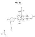
- Fig. 12 is an enlarged view of a tension measurement section.
- a printing apparatus 200 according to the present embodiment will be described with reference to these drawings. Additionally, constituent sites that are the same as those of Embodiment 1 will be given the same reference numerals, and overlapping descriptions thereof will be omitted.
- the printing apparatus 200 includes tension measurement sections 110 and 130 that measure an amount of tension that is applied to a recording medium 95 on at least one of an upstream side and a downstream side of the endless belt 26 in the movement direction of the recording medium 95.
- the printing apparatus 200 of the present embodiment includes the tension measurement sections 110 and 130 on both the upstream side and the downstream side.
- the recording medium transport section 20 includes a transport roller 21, a movable roller 122, a transport roller 23, a belt rotation roller 24, a belt driving roller 25, an endless belt 26, a transport roller 27, a movable roller 128 and a transport roller 29.
- the transport rollers 21 and 23, and the movable roller 122 relay a recording medium 95 from the recording medium supply section 10 to the endless belt 26.
- the movable roller 122 is provided between the transport roller 21 and the transport roller 23, and is configured so as to be movable in the vertical direction (the Z axis direction).
- the movable roller 122 is a constituent component of the tension measurement section 110, which measures an amount of tension of a recording medium 95 that is supplied to the endless belt 26 from the recording medium supply section 10.
- the transport rollers 27 and 29, and the movable roller 128 relay a recording medium 95 from the endless belt 26 to the recording medium recovery section 30.
- the movable roller 128 is provided between the transport roller 27 and the transport roller 29, and is configured so as to be movable in the vertical direction (the Z axis direction).
- the movable roller 128 is a constituent component of the tension measurement section 130, which measures an amount of tension of a recording medium 95 that is recovered by the recording medium recovery section 30 from the endless belt 26.
- the tension measurement section 130 will be described. Additionally, since the tension measurement section 110 has the same configuration as the tension measurement section 130, description thereof will be omitted.
- the tension measurement section 130 is provided with the movable roller 128 and an optical sensor 140.
- the movable roller 128 has a predetermined mass, and the position of the movable roller 128 moves along the vertical direction (the Z axis direction) as a result of the amount of tension that is applied to a recording medium 95. That is, the movable roller 128 is positioned in the +Z axis direction in a case in which the amount of tension of a recording medium 95 is high, and the movable roller 128 is positioned in the -Z axis direction in a case in which the amount of tension of a recording medium 95 is low.
- a plurality of optical sensors 140 are provided along the Z axis direction in which the movable roller 128 moves.
- three optical sensors 140a, 140b and 140c are provided from the +Z axis direction toward the -Z axis direction.
- the optical sensors 140a, 140b and 140c detect the position of a lower end of the movable roller 128.
- the optical sensors 140a, 140b and 140c are configured to include a light emission section, which includes a light emitting element, or the like, that emits light, and a light reception section, which includes a light receiving element, or the like, that receives light emitted from the light emission section.
- Optical axes of the light emission sections are directed toward the movable roller 128, which is movable in the Z axis direction.
- the optical sensors 140a, 140b and 140c output an "ON" signal when reflected light that is reflected by a recording medium 95 is received, and an "OFF" signal when it is not possible to receive reflected light.
- the optical sensor 140a outputs the "ON” signal
- the optical sensors 140b and 140c output the "OFF" signal.
- the optical sensors 140a, 140b and 140c output the "ON" signal.
- the control section 1 can determine the position of the movable roller 128 in the Z axis direction by analyzing the signals that are output from the optical sensors 140a, 140b and 140c. In addition, since the position of the movable roller 128 in the Z axis direction is proportionate to the amount of tension that is applied to a recording medium 95, the control section 1 can detect the amount of tension that is being applied to a recording medium 95 by determining the position of the movable roller 128 in the Z axis direction. Additionally, in the present embodiment, a configuration example that uses three optical sensors is shown, but configurations that use one or two optical sensors or four or more optical sensors, may also be used. It is possible to reduce the cost of the tension measurement sections in a case of a configuration using one or two optical sensors.
- a method that uses the optical sensors 140 is illustrated by way of example as a method for determining the position of the movable roller 128 in the Z axis direction, but a method that uses a laser length measurement machine may also be used.
- the printing apparatus 200 includes a roller correction table acquisition unit that acquires a roller correction table, and a belt correction table acquisition unit that acquires a belt correction table. Roller correction tables and belt correction tables that are acquired using the acquisition units by including amounts of tension that can be measured by the tension measurement sections 110 and 130 as a parameter, are saved in the storage section 5.
- the control section 1 of the printing apparatus 200 selects a roller correction table and a belt correction table that match amounts of tension that are measured by the tension measurement sections 110 and 130 at the time of printing.
- the control section 1 selects a roller correction table and a belt correction table that match the amounts of tension that are measured by the tension measurement sections 110 and 130, from the plurality of roller correction tables and the plurality of belt correction tables that are saved in the storage section 5 by performing acquisition including the tension as a parameter.
- correction values ⁇ and ⁇ that include movement errors of the endless belt 26 caused by amounts of tension of a recording medium 95 in a case in which there are fluctuations in the amount of tension of a recording medium 95 at the time of printing.
- the control section 1 calculates a feed out amount (a rotation amount) of the belt driving roller 25 using the correction values ⁇ and ⁇ .
- the control section 1 moves the endless belt 26 by rotating the belt driving roller 25 by the calculated feed out amount, as a result of controlling the belt driving roller 25. As a result of this, a recording medium 95, which is mounted on the endless belt 26, is transported in the transport direction.
- the printing apparatus 200 is provided with the tension measurement sections 110 and 130 that measure the amount of tension of a recording medium 95. Since the control section 1 selects a roller correction table and a belt correction table that match the amount of tension that is measured by the tension measurement sections 110 and 130, it is even possible to obtain correction values ⁇ and ⁇ that include a movement error of the endless belt 26 caused by amounts of tension of a recording medium 95 in a case in which there are fluctuations in the amount of tension of a recording medium 95 during printing. As a result of this, since the movement accuracy of the endless belt 26 and the transport accuracy of a recording medium 95, which is mounted on the endless belt 26, is improved, it is possible to improve the printing quality of an image that is formed on the recording medium 95.
Landscapes
- Engineering & Computer Science (AREA)
- Textile Engineering (AREA)
- Ink Jet (AREA)
- Handling Of Sheets (AREA)
- Controlling Rewinding, Feeding, Winding, Or Abnormalities Of Webs (AREA)
Description
- The present invention relates to a printing apparatus.
- In recent years, an ink jet type printing apparatus that performs printing of patterns, or the like, on a fabric by discharging an ink toward an outer surface of the fabric, has been used in textile printing on fabrics such as cotton, silk, wool, chemical fibers, and blended fabrics. In order to handle a stretchable fabric as a recording medium, a printing apparatus that is used in textile printing moves a recording medium by mounting the recording medium on an endless belt having a sticky property. In this kind of printing apparatus, an error in the movement amount of the endless belt occurs due to variations in the dimensions in the thickness direction of the endless belt. Therefore, for example, Japanese Patent No.
5332884 - In a printing apparatus that is provided with this kind of endless belt, in addition to variations in the thickness of the endless belt, a movement error amount of an endless belt differs depending on various printing conditions that are stipulated at a time of printing such as decentering of a belt driving roller that moves the endless belt, the type of recording medium, and the like. However, the printing apparatus that is disclosed in Japanese Patent No.
5332884 - The invention can be realized in the following aspects or application examples. Application Example 1
- According to this application example, there is provided a printing apparatus including a driving roller, an endless belt that transports a recording medium using rotation of the driving roller, a roller correction table acquisition unit that acquires a roller correction table, which represents a relationship between a point of origin position of the driving roller and a movement error of the endless belt, a belt correction table acquisition unit that acquires a belt correction table, which represents a relationship between a point of origin position of the endless belt and a movement error of the endless belt, and a control section that controls driving of the driving roller by calculating a rotation amount of the driving roller on the basis of the roller correction table and the belt correction table.
- According to the application example, the printing apparatus includes the roller correction table acquisition unit that acquires a roller correction table, which represents a relationship between a point of origin position of the driving roller and a movement error of the endless belt. In other words, the printing apparatus includes a unit that determines a movement error of the endless belt caused by decentering of the driving roller. In addition, the printing apparatus includes a belt correction table acquisition unit that acquires a belt correction table, which represents a relationship between a point of origin position of the endless belt and a movement error of the endless belt. In other words, the printing apparatus includes a unit that determines a movement error of the endless belt caused by the thickness of the endless belt. Since the control section of the printing apparatus drives the driving roller by calculating a rotation amount of the driving roller on the basis of the roller correction table and the belt correction table, a movement error of the endless belt caused by decentering of the driving roller is corrected in addition to variations in the thickness of the endless belt. As a result of this, since the movement accuracy of the endless belt and the transport accuracy of a recording medium, which is mounted on the endless belt, are improved, it is possible to improve the printing quality of an image that is formed on the recording medium. Accordingly, it is possible to provide a printing apparatus in which the transport accuracy of a recording medium is improved and the printing quality of an image is improved.
- It is preferable that the printing apparatus according to the application example further includes roller correction tables and belt correction tables that correspond to printing conditions that are stipulated at a time of printing, and that the control section selects a roller correction table and a belt correction table that match the stipulated printing conditions.
- According to the application example, the printing apparatus includes roller correction tables and a belt correction tables that are acquired on the basis of various printing conditions that are stipulated at the time of printing. As a result of the control section of the printing apparatus driving the driving roller by calculating a rotation amount of the driving roller by selecting a roller correction table and a belt correction table that match the stipulated printing conditions, it is possible to perform correction that includes a movement error of the endless belt caused by the printing conditions.
- In the printing apparatus according to the application example, it is preferable that the printing conditions include printing quality.
- According to the application example, the printing apparatus includes the roller correction tables and a belt correction tables that are acquired on the basis of a printing quality that is stipulated at the time of printing. For example, a mode in which printing quality is prioritized, a mode in which printing velocity is prioritized, and the like, are examples of the printing quality. More specifically, the printing velocity differs depending on the printing quality. Since a movement error of the endless belt differs depending on the printing velocity, the printing apparatus of the present application example can perform correction that includes a movement error of the endless belt caused by differences in the printing velocity, which depends on the printing quality.
- In the printing apparatus according to the application example, it is preferable that the printing conditions include a medium type of the recording medium.
- According to the application example, the printing apparatus includes the printing roller correction tables and a belt correction tables that are acquired on the basis of a recording medium to be used in the printing. Since a movement error of the endless belt differs depending on the stretchability, and the like, of a recording medium to be used, the printing apparatus of the present application example can perform correction that includes a movement error of the endless belt caused by the recording medium to be used.
- In the printing apparatus according to the application example, it is preferable that the printing conditions include a condition relating to a tension at a time of transporting the recording medium.
- According to the application example, the printing apparatus includes roller correction tables and a belt correction tables that are acquired on the basis of a condition relating to a tension that is applied when transporting the recording medium, the condition being stipulated at the time of printing. For example, a "tension mode" that transports a recording medium by applying a predetermined amount of tension thereto, and a "slack mode" that reduces damage and transports a recording medium, and the like, are examples of transport methods. Since the amount of a movement error of the endless belt differs depending on a transport mode of a recording medium, the printing apparatus of the present application example can perform correction that includes a movement error of the endless belt caused by the transport method of the recording medium.
- It is preferable that the printing apparatus according to the application example further includes a tension measurement section that measures an amount of tension that is applied to the recording medium on at least one of an upstream side and a downstream side of the endless belt in a movement direction of the recording medium; and roller correction tables and belt correction tables that correspond to tension that can be measured by the tension measurement section, and that the control section selects a roller correction table and a belt correction table that match the tension that is measured by the tension measurement section.
- According to the application example, the printing apparatus includes the roller correction tables and a belt correction tables that are acquired on the basis of an amount of tension of the recording medium, which is measured by the tension measurement section. Since the control section selects a roller correction table and a belt correction table that match the tension that is measured by the tension measurement section, it is even possible to perform correction that includes a movement error of the endless belt caused by tension in a case in which there are fluctuations in the amount of tension of a recording medium during printing.
- Embodiments of the invention will now be described by way of example only with reference to the accompanying drawings, wherein like numbers reference like elements.
-
Fig. 1 is a schematic diagram that schematically shows an overall configuration of a printing apparatus according toEmbodiment 1. -
Fig. 2 is a perspective view in which an endless belt is displayed in an enlarged manner. -
Fig. 3 is a cross-sectional view of a movement amount detection sensor. -
Fig. 4 is an electrical block diagram that shows an electrical configuration of the printing apparatus. -
Fig. 5 is a view that shows an example of a transport error of the endless belt. -
Fig. 6 is a view that describes a point of origin of a driving axis of a belt driving roller. -
Fig. 7 is a view that shows an example of a roller correction table. -
Fig. 8 is a view that describes a belt phase of the endless belt. -
Fig. 9 is a view that shows an example of a belt correction table. -
Fig. 10 is a flowchart that describes a printing operation of the printing apparatus. -
Fig. 11 is a schematic diagram that schematically shows an overall configuration of a printing apparatus according toEmbodiment 2. -
Fig. 12 is an enlarged view of a tension measurement section. - Hereinafter, embodiments of the invention will be described with reference to the drawings. Additionally, in each of the drawings below, the scale of each layer and each member is altered from a practical scale in order to make each layer and each member have a size that is easy to understand.
- In addition, in
Figs. 1 to 3 andFigs. 6 ,8 ,11 and12 , for the sake of convenience, an X axis, a Y axis and a Z axis are illustrated as three axes that are orthogonal to one another, a tip end side of an arrow that illustrates an axial direction is referred to as a "+ side", and a base end side thereof is referred to as a "- side". In addition, hereinafter, a direction that is parallel to the X axis is referred to as an "X axis direction", a direction that is parallel to the Y axis is referred to as a "Y axis direction" and a direction that is parallel to the Z axis is referred to as a "Z axis direction". -
Fig. 1 is a schematic diagram that schematically shows an overall configuration of a printing apparatus according toEmbodiment 1. Aprinting apparatus 100 is an apparatus that performs textile printing on arecording medium 95 by forming an image, or the like on therecording medium 95. For example, a fabric such as cotton, wool, a chemical fiber or a blended fabric can be used as therecording medium 95. In the present embodiment, a configuration that forms an image on a band-like recording medium 95 using a roll method will be illustrated by way of example, but the embodiment is not limited to this configuration. For example, the embodiment may use a method such as a sheet technique. - As shown in
Fig. 1 , theprinting apparatus 100 includes a recordingmedium supply section 10, a recordingmedium transport section 20, a recordingmedium recovery section 30, aprinting section 40, acleaning unit 50, amedium adhesion section 60, a dryingsection 97, and the like. Further, theprinting apparatus 100 includes acontrol section 1 that controls each of these sections. Each section of theprinting apparatus 100 is attached to aframe section 92. - The recording
medium supply section 10 is a section that supplies arecording medium 95 on which an image is to be formed, to aprinting section 40 side. The recordingmedium supply section 10 includes asupply shaft section 11 and abearing section 12. Thesupply shaft section 11 is formed in a cylindrical shape or a columnar shape, and is provided so as to be rotatable in a circumferential direction. A band-like recording medium 95 is wound around thesupply shaft section 11 in roll shape. Thesupply shaft section 11 is attached to thebearing section 12 in an attachable and detachable manner. As a result of this, arecording medium 95 in a state of being wound around thesupply shaft section 11 in advance, can be attached to thesupply shaft section 11 and thebearing section 12. - The bearing
section 12 supports both ends in an axial direction of thesupply shaft section 11 in a rotatable manner. The recordingmedium supply section 10 includes a rotational driving section (not illustrated in the drawing) that drives thesupply shaft section 11 in a rotational manner. The rotational driving section rotates thesupply shaft section 11 in a direction in which arecording medium 95 is fed out. The operation of the rotational driving section is controlled by thecontrol section 1. - The recording
medium transport section 20 is a section that transports arecording medium 95 from the recordingmedium supply section 10 to the recordingmedium recovery section 30. The recordingmedium transport section 20 includes atransport roller 21, atension roller 22, atransport roller 23, abelt rotation roller 24, abelt driving roller 25 as a driving roller, anendless belt 26, atransport roller 27, atension roller 28 and atransport roller 29. - The
transport rollers tension roller 22 relay arecording medium 95 from the recordingmedium supply section 10 to theendless belt 26. Thetransport rollers frame section 92, and thetension roller 22 is provided between thetransport roller 21 and thetransport roller 23, and is a movable roller that is movable in a vertical direction (the Z axis direction). As a result of being able to move thetension roller 22 in the vertical direction, the amount of tension of arecording medium 95, which is supplied to theendless belt 26 from the recordingmedium supply section 10, can be varied. - The
endless belt 26 is formed in an endless shape in which both end portions of a band-like belt are connected to one another, and is hung on thebelt rotation roller 24 and thebelt driving roller 25. Theendless belt 26 is maintained in a state in which a predetermined tension is applied thereto so that a portion between thebelt rotation roller 24 and thebelt driving roller 25 is parallel to afloor surface 99. Asticky layer 26c, which causes arecording medium 95 to stick to theendless belt 26, is provided on an outer surface (a support surface) 26a of theendless belt 26. Theendless belt 26 supports (maintains) arecording medium 95, which is supplied from thetransport roller 23, and is adhered to thesticky layer 26c by themedium adhesion section 60, which will be described later. As a result of this, it is possible to handle a stretchable fabric, or the like as arecording medium 95. - The
belt rotation roller 24 and thebelt driving roller 25 support an innercircumferential surface 26b of theendless belt 26. Additionally, a configuration in which a support section that supports theendless belt 26, is provided between thebelt rotation roller 24 and thebelt driving roller 25, may also be used. - The
endless belt 26 moves a recording medium using rotation of thebelt driving roller 25. To explain in more detail, when thebelt driving roller 25 is driven, theendless belt 26 rotates in accordance with rotation of thebelt driving roller 25, and thebelt rotation roller 24 rotates due to rotation of theendless belt 26. As a result of rotation of theendless belt 26, arecording medium 95, which is supported on theendless belt 26, is transported in a predetermined transport direction, which is illustrated by an arrow, and an image is formed on therecording medium 95 by theprinting section 40, which will be described later. In the present embodiment, arecording medium 95 is supported on a side (a +Z axis side) on which theouter surface 26a of theendless belt 26 faces theprinting section 40, and therecording medium 95 is transported from abelt rotation roller 24 side to abelt driving roller 25 side along with theendless belt 26. In addition, on a side (a -Z axis side) on which theouter surface 26a of theendless belt 26 faces thecleaning unit 50, only theendless belt 26 moves from thebelt driving roller 25 side to thebelt rotation roller 24 side. - The
transport roller 27 causes arecording medium 95, on which an image is formed, to peel away from thesticky layer 26c of theendless belt 26. Thetransport rollers tension roller 28 relay arecording medium 95 from theendless belt 26 to the recordingmedium recovery section 30. Thetransport rollers frame section 92, and thetension roller 28 is provided between thetransport roller 27 and thetransport roller 29, and is a movable roller that is movable in the vertical direction (the Z axis direction). As a result of being able to move thetension roller 28 in the vertical direction, the amount of tension of arecording medium 95, which is peeled away from theendless belt 26 and recovered by the recordingmedium recovery section 30, can be varied. Additionally, a "tension mode", and a "slack mode", which will be described later, and which are conditions relating to the tension when transporting therecording medium 95, are realized due to the movability of thetension rollers - The recording
medium recovery section 30 recovers arecording medium 95 that is transported by the recordingmedium transport section 20. The recordingmedium recovery section 30 includes a wind-upshaft section 31 and abearing section 32. The wind-upshaft section 31 is formed in a cylindrical shape or a columnar shape, and is provided so as to be rotatable in a circumferential direction. A band-like recording medium 95 is wound up onto the wind-upshaft section 31 in roll shape. The wind-upshaft section 31 is attached to thebearing section 32 in an attachable and detachable manner. As a result of this, arecording medium 95 in a state of being wound-up onto the wind-upshaft section 31, is released along with the wind-upshaft section 31. - The bearing
section 32 supports both ends in an axial direction of the wind-upshaft section 31 in a rotatable manner. The recordingmedium recovery section 30 includes a rotational driving section (not illustrated in the drawing) that drives the wind-upshaft section 31 in a rotational manner. The rotational driving section rotates the wind-upshaft section 31 in a direction in which arecording medium 95 is wound up. The operation of the rotational driving section is controlled by thecontrol section 1. - Additionally, in the present embodiment, a drying
section 97 is disposed between thetransport roller 27 and thetension roller 28. The dryingsection 97 is a section that dries an image formed on arecording medium 95. For example, by including an IR heater in thedrying section 97, and driving the IR heater, it is possible to dry an image formed on arecording medium 95 in a short period of time. As a result of this, it is possible to wind up a band-like recording medium 95 on which an image is formed, onto the wind-upshaft section 31. - The
medium adhesion section 60 is a section that causes arecording medium 95 to adhere to theendless belt 26. Themedium adhesion section 60 is disposed further on an upstream side (a -X axis side) than theprinting section 40 in the transport direction of arecording medium 95. Themedium adhesion section 60 includes apressing roller 61, a pressingroller driving section 62 and aroller support section 63. Thepressing roller 61 is formed in a cylindrical shape or a columnar shape, and is provided rotatable so as to be rotatable in a circumferential direction. Thepressing roller 61 is disposed so that an axial direction thereof intersects the transport direction in a manner in which thepressing roller 61 rotates in a direction along the transport direction. Theroller support section 63 is provided on an innercircumferential surface 26b side of theendless belt 26, which faces thepressing roller 61 with theendless belt 26 interposed therebetween. - The pressing
roller driving section 62 moves thepressing roller 61 in the transport direction (a +X axis direction) and a direction (a -X axis direction) that is opposite to the transport direction while pressing thepressing roller 61 toward a lower side in the vertical direction (the -Z axis side). Arecording medium 95 that is transported from thetransport roller 23, and superimposed on theendless belt 26, is pressed against theendless belt 26 between thepressing roller 61 and theroller support section 63. As a result of this, it is possible to reliably cause arecording medium 95 to stick to thesticky layer 26c, which is provided on theouter surface 26a of theendless belt 26, and therefore, it is possible to prevent lifting of arecording medium 95 above theendless belt 26. - The
printing section 40 includes an ink jettype discharge head 42 that discharges an ink toward arecording medium 95 as liquid droplets, acarriage movement section 41 that moves acarriage 43, in which thedischarge head 42 is mounted, and the like. Theprinting section 40 is disposed above a disposition position of the endless belt 26 (on the +Z axis side). Adischarge surface 44, on which a plurality ofnozzle rows 45 are formed, is provided in thedischarge head 42. For example, fournozzle rows 45 are formed on thedischarge surface 44, and a different color of ink (for example, cyan: C, magenta: M, yellow: Y and black: K) is discharged from eachnozzle row 45. Thedischarge surface 44 faces arecording medium 95 that is transported by theendless belt 26. - The
carriage movement section 41 moves thedischarge head 42 in a direction that intersects the transport direction of a recording medium 95 (a width direction of a recording medium 95 (the Y axis direction)). Thecarriage 43 is supported by a guide rail (not illustrated in the drawing), which is disposed along the Y axis direction, and thecarriage 43 is configured so as to be able to reciprocate in a ±Y axis direction as a result of thecarriage movement section 41. For example, it is possible to use a configuration in which a ball screw and a ball nut are combined, a linear guide mechanism or the like, as thecarriage movement section 41. - Furthermore, a motor (not illustrated in the drawing) is provided in the
carriage movement section 41 as a motive power source for moving thecarriage 43 along the Y axis direction. When the motor is driven due to the control of thecontrol section 1, thedischarge head 42 reciprocates along the Y axis direction along with thecarriage 43. Additionally, in the present embodiment, a serial head type discharge head, which is installed in a movable carriage and discharges an ink while moving in the width direction of a recording medium 95 (the ±Y axis direction), is illustrated as thedischarge head 42 by way of example, but a line head type in which the discharge head is fixedly arranged extending in the width direction of a recording medium 95 (the Y axis direction) may be used instead. - The
printing apparatus 100 is provided with thecleaning unit 50 for cleaning theendless belt 26. Thecleaning unit 50 includes acleaning section 51, apressing section 52 and amovement section 53. Themovement section 53 can be fixed in a predetermined position by moving thecleaning unit 50 along thefloor surface 99 in an integral manner. Thecleaning unit 50 is disposed between thebelt rotation roller 24 and thebelt driving roller 25 in the X axis direction. - The
pressing section 52 is an elevation device that is configured by anair cylinder 56 and aball bush 57, and is capable of moving thecleaning section 51, which is provided above thepressing section 52, between a cleaning position and a retreat position. The cleaning position is a position in which acleaning roller 58 and ablade 55 abut against theendless belt 26. The retreat position is a position in which the cleaningroller 58 and theblade 55 are separated from theendless belt 26. In the cleaning position, thecleaning section 51 cleans theouter surface 26a (the support surface) of theendless belt 26, which is hanging in a state in which a predetermined amount of tension is applied between thebelt rotation roller 24 and thebelt driving roller 25, from below (a -Z axis direction). Additionally,Fig. 1 shows a case in which thecleaning section 51 is raised and disposed in the cleaning position. - The
cleaning section 51 includes a cleaningtub 54, the cleaningroller 58 and theblade 55. The cleaningtub 54 is a tub in which a cleaning solution that is used in the cleaning of ink and foreign matter that is attached to theouter surface 26a of theendless belt 26, is retained, and the cleaningroller 58 and theblade 55 are provided on an inner side of the cleaningtub 54. For example, it is possible to use water, a water-soluble solvent (an alcohol aqueous solution or the like), or the like, as the cleaning solution, and a surfactant, an antifoaming agent, and the like may be added thereto according to necessity. - A lower side (the -Z axis side) of the cleaning
roller 58 is immersed in the cleaning solution that is retained in the cleaningtub 54. When the cleaningroller 58 is rotated in the cleaning position, the cleaning solution is supplied to theouter surface 26a of theendless belt 26, and the cleaningroller 58 slides along theendless belt 26. As a result of this, ink and fibers or the like of a fabric of arecording medium 95, which are attached to theendless belt 26, are washed away using the cleaningroller 58. - For example, the
blade 55 is configured by a material having a flexible property such as a silicon rubber. Theblade 55 is provided further on a downstream side than the cleaningroller 58 in the transport direction of theendless belt 26. Cleaning solution that remains on theouter surface 26a of theendless belt 26, is removed as a result of theendless belt 26 sliding along theblade 55. -
Fig. 2 is a perspective view in which an endless belt is displayed in an enlarged manner.Fig. 3 is a cross-sectional view of a movement amount detection sensor. A movementamount detection sensor 70 and a belt point oforigin sensor 80 that determine a point of origin position and a movement amount of theendless belt 26 will be described with reference toFigs. 2 and 3 . - The belt point of
origin sensor 80 is a sensor that detects a point of origin of theendless belt 26. As shown inFig. 2 ,markers 81 are provided at both end portions in the width direction of the endless belt 26 (the Y axis direction) on theouter surface 26a, on which thesticky layer 26c is not formed, as points of origin of theendless belt 26. The belt point oforigin sensor 80 is provided above (in a +Z axis direction) themarker 81 in the vertical direction. When themarker 81 moves in accordance with movement of theendless belt 26 and passes under the belt point oforigin sensor 80, the belt point oforigin sensor 80 detects themarker 81 and outputs a detection signal thereof. - The movement
amount detection sensor 70 is a sensor that performs image process measurement of a practical (or an actual amount of movement in practice) movement amount of theendless belt 26. The movementamount detection sensor 70 captures images for determining a practical movement amount that theendless belt 26 moves in a practical sense through comparison of positions before movement and after movement of theendless belt 26. As shown inFigs. 2 and 3 , the movementamount detection sensor 70 is provided in a position that faces the printing section 40 (refer toFig. 1 ) with theendless belt 26 interposed therebetween, and captures images of the innercircumferential surface 26b of theendless belt 26. - Additionally, in the present embodiment, a configuration in which the movement
amount detection sensor 70 is provided on the innercircumferential surface 26b of theendless belt 26 is shown, but the movementamount detection sensor 70 is not limited to this configuration. The movementamount detection sensor 70 may be provided in any position in which it is possible to capture images of theouter surface 26a, on which thesticky layer 26c of theendless belt 26 is not formed, the outer surface of arecording medium 95 that is mounted on theendless belt 26, or the like. In addition, it is preferable that the movementamount detection sensor 70 is provided in the vicinity of theprinting section 40. In addition, in a case in which images of theouter surface 26a or the innercircumferential surface 26b of theendless belt 26 are captured, it is preferable that undulations are formed on the outer surface of a target of the image capture section. As a result of this, since a clear image is captured, the calculate accuracy of the movement amount of theendless belt 26 is improved. - As shown in
Fig. 3 , the movementamount detection sensor 70 is provided with a light-emittingsection 72, a condensinglens 73, and animage capturing element 74 on an inner side of acase 76. - The
case 76 configures the exterior of the movementamount detection sensor 70. Thecase 76 has a truncated cone shape, and a light-transmissive glass 71 is attached to a tip end portion (an upper end portion) thereof. The light-transmissive glass 71 faces a gap between the light-transmissive glass 71 and the innercircumferential surface 26b of theendless belt 26 in a vertical manner in a state in which a gap is interposed therebetween. - The light-emitting
section 72 is a section that radiates light toward theendless belt 26. The light-emittingsection 72 is provided on an inner wall surface of thecase 76 with an angled posture in which it is possible to emit light toward the light-transmissive glass 71. For example, it is possible to use a light emitting diode (LED) as the light-emittingsection 72. - The condensing
lens 73 is a lens that condenses reflected light that passes through the light-transmissive glass 71 for a second time and is incident to the inside of thecase 76 after light that is emitted from the light-emittingsection 72 and passes through the light-transmissive glass 71 is reflected by the innercircumferential surface 26b of theendless belt 26, and is provided in a cylindrical portion of thecase 76. - The
image capturing element 74 is an element that captures images of the innercircumferential surface 26b of theendless belt 26, which are condensed by the condensinglens 73, and includes animage capturing surface 74a in a position in which images are formed. Theimage capturing element 74 is provided on an inner bottom surface of thecase 76. Additionally, the condensinglens 73 is retained at a height at which an image of the innercircumferential surface 26b of theendless belt 26 on theimage capturing surface 74a of theimage capturing element 74 can obtained, by aretention member 75. - The movement
amount detection sensor 70 outputs image capturing data that is captured by theimage capturing element 74, to thecontrol section 1. Thecontrol section 1 compares image capturing data before and after movement of theendless belt 26, and outputs a practical movement amount that theendless belt 26 has moved in a practical sense. - Additionally, in the present embodiment, a method that uses the movement
amount detection sensor 70 as a measurement method of the practical movement amount of theendless belt 26, is illustrated by way of example, but the measurement method is not limited to this configuration. The measurement method of the practical movement amount of theendless belt 26 may be a method that uses a laser length measurement machine. For example, it is possible to measure the practical movement amount of theendless belt 26 by providing a reflective body, which reflects laser light emitted along a movement direction of theendless belt 26, on theendless belt 26, and measuring a distance between a laser length measurement machine and the reflective body, which moves along with theendless belt 26. In addition, it is possible to determine the practical movement amount of theendless belt 26 by repeating movement of theendless belt 26 and the discharge of liquid droplets onto arecording medium 95 such as photographic paper, and measuring a position of a measurement pattern (dots) that is formed on therecording medium 95. -
Fig. 4 is an electrical block diagram that shows an electrical configuration of the printing apparatus. Next, the electrical configuration of theprinting apparatus 100 will be described with reference toFig. 4 . - The
control section 1 is a control unit for performing control of theprinting apparatus 100. Thecontrol section 1 is configured to include acontrol circuit 4, an interface section (I/F) 2, a CPU (Central Processing Unit) 3, and astorage section 5. Theinterface section 2 is a section for performing the communication of data between anexternal apparatus 6, which handles images, such as a computer or a digital camera, and theprinting apparatus 100. TheCPU 3 is an arithmetic processing device for performing an input signal process fromvarious detector groups 7 and overall control of theprinting apparatus 100. Thedetector groups 7 include the movementamount detection sensor 70 for measuring the movement amount of theendless belt 26, the belt point oforigin sensor 80 that detects a belt point of origin of theendless belt 26, and a driving shaft point oforigin sensor 85 that detects a driving shaft point of origin of thebelt driving roller 25. - The
storage section 5 is a section for securing a region that stores a program of theCPU 3, a work region, or the like, and includes storage elements such as RAM (Random Access Memory), EEPROM (Electrically Erasable Programmable Read-Only Memory), or the like. In addition, roller correction tables and belt correction tables that correct a transport error of theendless belt 26, which will be described later, are stored in thestorage section 5. - The
CPU 3 controls thebelt driving roller 25 that moves theendless belt 26 in the transport direction, thecarriage movement section 41 that moves thecarriage 43, in which thedischarge head 42 is mounted, in a direction that intersects the transport direction, thedischarge head 42 that discharges ink toward arecording medium 95, and each device that is not illustrated in the drawings, on the basis of printing data and printing conditions that are received from theexternal apparatus 6 using thecontrol circuit 4. Additionally, for example, a printing quality, which is represented by "clear", "fast", or the like, a medium type to be used as arecording medium 95, a condition relating to the tension when transporting the recording medium, which is represented by a "tension mode", a "slack mode", or the like, are included as the printing conditions of the present embodiment. - Next, a transport error of the
endless belt 26 will be described. -
Fig. 5 is a view that shows an example of a transport error of the endless belt. The horizontal axis inFig. 5 represents an integrated movement amount when theendless belt 26 is rotated a single time by repeatedly moving theendless belt 26 by a predetermined movement amount from a predetermined position (for example, a point of origin position of the marker 81). That is, a maximum value of the horizontal axis inFig. 5 is equivalent to the length of theendless belt 26. The vertical axis inFig. 5 represents a difference (hereinafter, also referred to as a transport error) between practical movement amounts, which are calculated from image capturing data that is captured before and after movement of theendless belt 26, with respect to a predetermined (or intended) movement amount. - As shown in
Fig. 5 , in the transport error, an error that is expressed periodically in a period of an interval A, and an error, which is shown by an interval B, that is expressed specifically. The length of the interval A is substantially equivalent to the length of the outer periphery of thebelt driving roller 25, and it can be understood that the transport error of the interval A is caused by driving of thebelt driving roller 25. The reason for this is that the interval A is a so-called transport error that occurs as a result of decentering of thebelt driving roller 25, in which the center of the circumference (the outer periphery) of thebelt driving roller 25 and the center of the axis of rotation that drives thebelt driving roller 25 in a rotational manner, are shifted. The interval B is equivalent to a position of a connection section of theendless belt 26, and it can be understood that the transport error of the interval B is caused by the thickness of theendless belt 26. Additionally, a transport error caused by the thickness of theendless belt 26 in portions other than a connection section of theendless belt 26, are also included in practice. -
Fig. 6 is a view that describes a point of origin of a driving axis of a belt driving roller. Thebelt driving roller 25 is provided with the driving shaft point oforigin sensor 85. In addition, in the present description, the position of the driving shaft point oforigin sensor 85 is set as a reference position of thebelt driving roller 25. For example, it is possible to use a rotary encoder, which is provided with a marker as a driving shaft point of origin, or the like, as the driving shaft point oforigin sensor 85. The position of the driving shaft point of origin moves as a result of rotational driving of thebelt driving roller 25. Additionally, in the following description, the position of the driving shaft point of origin represents an angle θ that is formed by a line that connects the center of thebelt driving roller 25 and the reference position, and a line that connects the center of thebelt driving roller 25 and the driving shaft point of origin. In this way, the point oforigin sensor 85 measures how much the driving roller has rotated. Additionally, the driving shaft point of origin of thebelt driving roller 25 may be determined using an absolute-type rotary encoder that outputs an absolute position of the driving shaft point of origin that depends on a rotational angle. -
Fig. 7 is a view that shows an example of a roller correction table. The roller correction table represents a relationship between a point of origin position of a driving roller and a movement error of the endless belt. In the present embodiment, a plurality of roller correction tables, which correspond to a plurality of printing conditions, are stored in thestorage section 5. - Positions of the driving shaft point of origin of the
belt driving roller 25 are shown using the angles θ in the parameters in the rows of the roller correction table that is shown inFig. 7 , and reference movement amounts Kn are shown as predetermined movement amounts of theendless belt 26 in the parameters of the rows. Further, correction values α of the movement amounts are shown in intersecting positions of the respective parameters (the angles θ and the reference movement amounts Kn). - A roller correction table acquisition unit, which acquires roller correction tables, calculates correction values α of movement amounts from the reference movement amounts Kn, by which the
control section 1 feeds out theendless belt 26 by driving (rotating) thebelt driving roller 25, and practical movement amounts of theendless belt 26, which are determined using the movementamount detection sensor 70. Correction values α of at least a single circuit (an amount that is equivalent to 360°) of thebelt driving roller 25 are determined as a result of thecontrol section 1 repeating rotation of thebelt driving roller 25 and calculation of the correction values α. As a result of this, it is possible to acquire the roller correction tables that are illustrated by way of example inFig. 7 , and correct movement errors caused by decentering of thebelt driving roller 25. Additionally, it is preferable that the correction values α are determined in a case in which the connection section of theendless belt 26 is not positioned at thebelt rotation roller 24 or thebelt driving roller 25. As a result of this, it is possible to eliminate the effects of transport errors caused by the thickness of theendless belt 26. -
Fig. 8 is a view that describes a belt phase of the endless belt. In the present description, the position of the belt point oforigin sensor 80 is set as a reference position of theendless belt 26. The position of themarker 81, as the point of origin position of theendless belt 26, moves as a result of rotational driving of thebelt driving roller 25. In the following description, a difference between themarker 81, as the point of origin position of theendless belt 26, and a reference position is represented by a belt phase D. -
Fig. 9 is a view that shows an example of a belt correction table. The belt correction table represents a relationship between a point of origin position of an endless belt and a movement error of the endless belt. In the present embodiment, a plurality of belt correction tables, which correspond to a plurality of printing conditions, are stored in thestorage section 5. - Point of origin positions (the positions of the markers 81) of the
endless belt 26 are shown using the belt phases D in the parameters in the rows of the belt correction table that is shown inFig. 9 , and reference movement amounts Kn are shown as predetermined movement amounts of theendless belt 26 in the parameters of the rows. Further, correction values σ of the movement amounts are shown in intersecting positions of the respective parameters (the belt phases D and the reference movement amounts Kn). - A belt correction table acquisition unit, which acquires belt correction tables, calculates correction values σ of movement amounts from the reference movement amounts Kn, by which the
control section 1 feeds out theendless belt 26 by driving (rotating) thebelt driving roller 25, and practical movement amounts of theendless belt 26, which are determined using the movementamount detection sensor 70. Correction values σ of at least a single circuit (an amount that is equivalent to 360°) of theendless belt 26 are determined as a result of thecontrol section 1 repeating rotation of thebelt driving roller 25 and calculation of the correction values σ. As a result of this, it is possible to acquire the belt correction tables that are illustrated by way of example inFig. 9 , and correct movement errors caused by the thickness of theendless belt 26. Additionally, at the time of acquiring the belt correction tables, it is possible to acquire correction values σ in which transport errors caused by decentering of thebelt driving roller 25 are eliminated, by determining the position (the angle θ) of the driving shaft point of origin of thebelt driving roller 25 and taking the roller correction table into consideration. - In the present embodiment, a roller correction table and a belt correction table that were acquired by driving the
printing apparatus 100 using printing conditions of "clear", "medium type A" and "tension mode" are illustrated by way of example, but the printing conditions are not limited to these printing conditions. For example, the correction values α and σ of the belt correction tables and the roller correction tables differ depending on printing conditions such as the printing quality, which is represented by "clear", "fast", or the like, the medium type to be used as arecording medium 95, a condition relating to the tension when transporting arecording medium 95, which is represented by the "tension mode", the "slack mode", or the like, and the like. Therefore, theprinting apparatus 100 of the present embodiment includes roller correction tables and belt correction tables that correspond to printing conditions that are stipulated at the time of printing. To explain in more detail, a plurality of roller correction tables and a plurality of belt correction tables, which are acquired by driving theprinting apparatus 100 on the basis of these printing conditions, are included in thestorage section 5. - The
control section 1 of theprinting apparatus 100 selects a roller correction table and a belt correction table that match the printing conditions stipulated at the time of printing. - To explain in more detail, in a case in which printing conditions that include printing quality are stipulated at the time of printing, the
control section 1 selects a roller correction table and a belt correction table that match the printing conditions including the stipulated printing quality, from the plurality of roller correction tables and the plurality of belt correction tables that are saved in thestorage section 5 by performing acquisition including the printing quality as a parameter. As a result of this, it is possible to obtain correction values α and σ that include movement errors of theendless belt 26 caused by differences in the printing velocity, which depends on the printing quality. - In a case in which printing conditions that include the medium type are stipulated at the time of printing, the
control section 1 selects a roller correction table and a belt correction table that match the printing conditions including the stipulated medium type, from the plurality of roller correction tables and the plurality of belt correction tables that are saved in thestorage section 5 by performing acquisition including the medium type of arecording medium 95 as a parameter. As a result of this, it is possible to obtain correction values α and σ that include movement errors of theendless belt 26 caused by differences in the type ofrecording medium 95. - In a case in which printing conditions that include the condition relating to the tension when transporting a
recording medium 95 are stipulated at the time of printing, thecontrol section 1 selects a roller correction table and a belt correction table that match the printing conditions including the stipulated condition relating to the tension, from the plurality of roller correction tables and the plurality of belt correction tables that are saved in thestorage section 5 by performing acquisition including the condition relating to the tension as a parameter. As a result of this, it is possible to obtain correction values α and σ that include movement errors of theendless belt 26 caused by differences in the condition relating to the amount of tension of arecording medium 95. -
Fig. 10 is a flowchart that describes a printing operation of the printing apparatus. A printing operation of theprinting apparatus 100 will be described with reference toFigs. 4 and10 . - In Step S1, printing data is received. The
CPU 3 receives printing data to record an image on arecording medium 95 and stipulated conditions from theexternal apparatus 6, and saves the printing data and printing conditions in thestorage section 5. - In Step S2, the selection of correction tables is performed. The
CPU 3 selects a roller correction table and a belt correction table that match the printing conditions received in Step S1 from a plurality of roller correction tables and a plurality of belt correction tables, which are saved in thestorage section 5 and are acquired by setting various printing conditions as parameters. For example, the printing quality, which is represented by "clear", "fast", or the like, the medium type to be used as arecording medium 95, the tension when transporting the recording medium, which is represented by a "tension mode", a "slack mode", or the like, are included as the printing conditions. For example, in a case in which the received printing conditions are "clear", "medium type A" and "tension mode", theCPU 3 selects the roller correction table that is shown inFig. 7 and the belt correction table that is shown inFig. 9 . - In Step S3, a feeding amount of the
belt driving roller 25 is calculated. The control section 1 (the CPU 3) calculates a rotation amount of thebelt driving roller 25 on the basis of the roller correction table and the belt correction table. To explain in more detail, theCPU 3 calculates a point of origin position (an angle θ) of thebelt driving roller 25 and a point of origin position (a belt phase D) of theendless belt 26 by receiving signals that are output from the belt point oforigin sensor 80 and the driving shaft point oforigin sensor 85. Further, a feed out amount (a rotation amount) of thebelt driving roller 25 is calculated by referring to the roller correction table and the belt correction table that were selected in Step S2. The feed out amount is a value in which a correction value α that is determined from the angle θ and a reference movement amount Kn, and a correction value σ that is determined from the belt phase D and the reference movement amount Kn, are added to the reference movement amount Kn. - In Step S4, the
recording medium 95 is transported and ink is discharged. Thecontrol section 1 moves theendless belt 26 by rotating thebelt driving roller 25 by the feed out amount that was calculated in Step S3, as a result of controlling the driving of thebelt driving roller 25. As a result of this, therecording medium 95, which is mounted on theendless belt 26, is transported in the transport direction. Further, thecontrol section 1 discharges ink from thedischarge head 42 toward therecording medium 95 while moving thecarriage 43 in a direction that intersects the transport direction of therecording medium 95, by controlling thecarriage movement section 41 and thedischarge head 42. - In Step S5, it is determined whether or not there is subsequent line of printing data. The
CPU 3 determines whether or not there is a subsequent line of printing data by referring to the printing data that is saved in thestorage section 5. In a case in which there is a subsequent line of printing data (Step S5: Yes), the process returns to Step S3 and the processes from Step S3 to Step S5 are repeated. In a case in which there is not a subsequent line of printing data (Step S5: No), thecontrol section 1 finishes the printing operation of theprinting apparatus 100. - As a result of the above-mentioned steps, since the movement accuracy of the
endless belt 26 and the transport accuracy of arecording medium 95, which is mounted on theendless belt 26, is improved, it is possible to improve the printing quality of an image that is formed on therecording medium 95. - In the abovementioned manner, according to the
printing apparatus 100 of the present embodiment, it is possible to obtain the following effects. - The
printing apparatus 100 includes a roller correction table acquisition unit that acquires a roller correction table that corrects a movement error caused by decentering of thebelt driving roller 25, and a belt correction table acquisition unit that acquires a belt correction table that corrects a movement error caused by the thickness of theendless belt 26. Thecontrol section 1 drives thebelt driving roller 25 by calculating a rotation amount of thebelt driving roller 25 on the basis of the roller correction tables and the belt correction tables that are saved in thestorage section 5. As a result of this, it is possible to correct a movement error of theendless belt 26 caused by decentering of thebelt driving roller 25 in addition to a movement error caused by variations in the thickness of theendless belt 26. Accordingly, it is possible to provide aprinting apparatus 100 that includes a unit that acquires a movement error of theendless belt 26 caused by decentering of thebelt driving roller 25, and is capable of correcting the movement error. - Since the
printing apparatus 100 includes the roller correction table acquisition unit and the belt correction table acquisition unit, it is possible to acquire roller correction tables and belt correction tables based on various printing conditions that theprinting apparatus 100 is provided with, and include the roller correction tables and the belt correction tables in thestorage section 5. Thecontrol section 1 selects a roller correction table and a belt correction table that match printing conditions stipulated at the time of printing, and corrects the movement errors of theendless belt 26 on the basis of these tables. As a result of this, it is possible to correct movement errors of theendless belt 26 caused by printing conditions. - Since the
printing apparatus 100 includes roller correction tables and belt correction tables that are acquired on the basis of printing quality, it is possible to perform correction that includes a movement error of theendless belt 26 caused by differences in the printing velocity, which depends on the printing quality. - Since the
printing apparatus 100 includes roller correction tables and belt correction tables that are acquired on the basis of the type ofrecording medium 95, it is possible to perform correction that includes a movement error of theendless belt 26 caused by differences in the type ofrecording medium 95. - Since the
printing apparatus 100 includes roller correction tables and belt correction tables that are acquired on the basis of the condition relating to the tension when transporting arecording medium 95, it is possible to perform correction that includes a movement error of theendless belt 26 caused by differences in the condition relating to the amount of tension of arecording medium 95. - According to the
printing apparatus 100, since the movement accuracy of theendless belt 26 and the transport accuracy of arecording medium 95, which is mounted on theendless belt 26, is improved, it is possible to improve the printing quality of an image that is formed on therecording medium 95. -
Fig. 11 is a schematic diagram that schematically shows an overall configuration of a printing apparatus according toEmbodiment 2.Fig. 12 is an enlarged view of a tension measurement section. Aprinting apparatus 200 according to the present embodiment will be described with reference to these drawings. Additionally, constituent sites that are the same as those ofEmbodiment 1 will be given the same reference numerals, and overlapping descriptions thereof will be omitted. Theprinting apparatus 200 includestension measurement sections recording medium 95 on at least one of an upstream side and a downstream side of theendless belt 26 in the movement direction of therecording medium 95. Theprinting apparatus 200 of the present embodiment includes thetension measurement sections - The recording
medium transport section 20 includes atransport roller 21, amovable roller 122, atransport roller 23, abelt rotation roller 24, abelt driving roller 25, anendless belt 26, atransport roller 27, amovable roller 128 and atransport roller 29. Thetransport rollers movable roller 122 relay arecording medium 95 from the recordingmedium supply section 10 to theendless belt 26. Themovable roller 122 is provided between thetransport roller 21 and thetransport roller 23, and is configured so as to be movable in the vertical direction (the Z axis direction). Themovable roller 122 is a constituent component of thetension measurement section 110, which measures an amount of tension of arecording medium 95 that is supplied to theendless belt 26 from the recordingmedium supply section 10. - The
transport rollers movable roller 128 relay arecording medium 95 from theendless belt 26 to the recordingmedium recovery section 30. Themovable roller 128 is provided between thetransport roller 27 and thetransport roller 29, and is configured so as to be movable in the vertical direction (the Z axis direction). Themovable roller 128 is a constituent component of thetension measurement section 130, which measures an amount of tension of arecording medium 95 that is recovered by the recordingmedium recovery section 30 from theendless belt 26. - Next, the
tension measurement section 130 will be described. Additionally, since thetension measurement section 110 has the same configuration as thetension measurement section 130, description thereof will be omitted. - The
tension measurement section 130 is provided with themovable roller 128 and anoptical sensor 140. Themovable roller 128 has a predetermined mass, and the position of themovable roller 128 moves along the vertical direction (the Z axis direction) as a result of the amount of tension that is applied to arecording medium 95. That is, themovable roller 128 is positioned in the +Z axis direction in a case in which the amount of tension of arecording medium 95 is high, and themovable roller 128 is positioned in the -Z axis direction in a case in which the amount of tension of arecording medium 95 is low. - A plurality of
optical sensors 140 are provided along the Z axis direction in which themovable roller 128 moves. In the present embodiment, threeoptical sensors optical sensors movable roller 128. Theoptical sensors movable roller 128, which is movable in the Z axis direction. - Light that is emitted from the light emission sections is received by the light reception sections in a case in of being reflected by a
recording medium 95 that is latched onto themovable roller 128. Theoptical sensors recording medium 95 is received, and an "OFF" signal when it is not possible to receive reflected light. For example, in a case in which themovable roller 128 is positioned in afirst position 128a, theoptical sensor 140a outputs the "ON" signal, and theoptical sensors movable roller 128 is positioned in athird position 128c, theoptical sensors - The
control section 1 can determine the position of themovable roller 128 in the Z axis direction by analyzing the signals that are output from theoptical sensors movable roller 128 in the Z axis direction is proportionate to the amount of tension that is applied to arecording medium 95, thecontrol section 1 can detect the amount of tension that is being applied to arecording medium 95 by determining the position of themovable roller 128 in the Z axis direction. Additionally, in the present embodiment, a configuration example that uses three optical sensors is shown, but configurations that use one or two optical sensors or four or more optical sensors, may also be used. It is possible to reduce the cost of the tension measurement sections in a case of a configuration using one or two optical sensors. It is possible to improve the measuring accuracy of the amount of tension that is applied to arecording medium 95 in a case of a configuration using four or more optical sensors. In addition, a method that uses theoptical sensors 140 is illustrated by way of example as a method for determining the position of themovable roller 128 in the Z axis direction, but a method that uses a laser length measurement machine may also be used. For example, it is possible to determine the position of themovable roller 128 in the Z axis direction by providing a laser length measurement machine, which emits laser light toward themovable roller 128 from vertically above or vertically below themovable roller 128. - The
printing apparatus 200 includes a roller correction table acquisition unit that acquires a roller correction table, and a belt correction table acquisition unit that acquires a belt correction table. Roller correction tables and belt correction tables that are acquired using the acquisition units by including amounts of tension that can be measured by thetension measurement sections storage section 5. - The
control section 1 of theprinting apparatus 200 selects a roller correction table and a belt correction table that match amounts of tension that are measured by thetension measurement sections - To explain in more detail, in a case in which amounts of tension that are measured by the
tension measurement sections control section 1 selects a roller correction table and a belt correction table that match the amounts of tension that are measured by thetension measurement sections storage section 5 by performing acquisition including the tension as a parameter. As a result of this, it is also possible to obtain correction values α and σ that include movement errors of theendless belt 26 caused by amounts of tension of arecording medium 95 in a case in which there are fluctuations in the amount of tension of arecording medium 95 at the time of printing. Thecontrol section 1 calculates a feed out amount (a rotation amount) of thebelt driving roller 25 using the correction values α and σ. - The
control section 1 moves theendless belt 26 by rotating thebelt driving roller 25 by the calculated feed out amount, as a result of controlling thebelt driving roller 25. As a result of this, arecording medium 95, which is mounted on theendless belt 26, is transported in the transport direction. - In the abovementioned manner, according to the
printing apparatus 200 of the present embodiment, it is possible to obtain the following effects. - The
printing apparatus 200 is provided with thetension measurement sections recording medium 95. Since thecontrol section 1 selects a roller correction table and a belt correction table that match the amount of tension that is measured by thetension measurement sections endless belt 26 caused by amounts of tension of arecording medium 95 in a case in which there are fluctuations in the amount of tension of arecording medium 95 during printing. As a result of this, since the movement accuracy of theendless belt 26 and the transport accuracy of arecording medium 95, which is mounted on theendless belt 26, is improved, it is possible to improve the printing quality of an image that is formed on therecording medium 95. - Where there are two
tension measurement sections - Once the correction tables have been acquired and stored, it is no longer necessary to use or retain the acquisition unit or the movement
amount detection sensor 70 unless the tables are to be updated or new tables are to be added. It is sufficient just to store the tables. - The foregoing description has been given by way of example only and it will be appreciated by a person skilled in the art that modifications can be made without departing from the scope of the present invention as defined by the claims.
Claims (7)
- A printing apparatus (100) comprising:a driving roller (25);an endless belt (26) for transporting a recording medium (95) using rotation of the driving roller;a roller correction table acquisition unit configured to acquire a roller correction table, which represents a relationship between a point of origin position of the driving roller and a movement error of the endless belt;a belt correction table acquisition unit configured to acquire a belt correction table, which represents a relationship between a point of origin position (81) of the endless belt and a movement error of the endless belt; anda control section (1) configured to control driving of the driving roller by calculating a rotation amount of the driving roller on the basis of the roller correction table and the belt correction table.
- A printing apparatus (100) comprising:a driving roller (25);an endless belt (26) for transporting a recording medium (95) using rotation of the driving roller;storage means storinga roller correction table acquisition unit configured to acquire a roller correction table, which represents a relationship between a point of origin position of the driving roller and a movement error of the endless belt; anda belt correction table, which represents a relationship between a point of origin position (81) of the endless belt and a movement error of the endless belt; anda control section (1) configured to control driving of the driving roller by calculating a rotation amount of the driving roller on the basis of the roller correction table and the belt correction table.
- The printing apparatus according to Claim 1 or Claim 2, further comprising:roller correction tables and belt correction tables that correspond to printing conditions that are stipulated at a time of printing;wherein the control section is configured to select a roller correction table and a belt correction table that match the stipulated printing conditions.
- The printing apparatus according to Claim 3,
wherein the printing conditions include printing quality. - The printing apparatus according to Claim 3 or claim 4,
wherein the printing conditions include a medium type of the recording medium. - The printing apparatus according to any one of claims 3 to 5,
wherein the printing conditions include a condition relating to a tension at a time of transporting the recording medium. - The printing apparatus according to any one of the preceding claims, further comprising:a tension measurement section (110, 130) configured to measure an amount of tension that is applied to the recording medium on at least one of an upstream side and a downstream side of the endless belt in a movement direction of the recording medium; androller correction tables and belt correction tables that correspond to amounts of tension that can be measured by the tension measurement section;wherein the control section is configured to select a roller correction table and a belt correction table that match the tension that is measured by the tension measurement section.
Applications Claiming Priority (1)
| Application Number | Priority Date | Filing Date | Title |
|---|---|---|---|
| JP2015179273A JP6705140B2 (en) | 2015-09-11 | 2015-09-11 | Printer |
Publications (3)
| Publication Number | Publication Date |
|---|---|
| EP3150391A2 true EP3150391A2 (en) | 2017-04-05 |
| EP3150391A3 EP3150391A3 (en) | 2017-09-27 |
| EP3150391B1 EP3150391B1 (en) | 2018-10-17 |
Family
ID=56883712
Family Applications (1)
| Application Number | Title | Priority Date | Filing Date |
|---|---|---|---|
| EP16187615.6A Active EP3150391B1 (en) | 2015-09-11 | 2016-09-07 | Printing apparatus |
Country Status (2)
| Country | Link |
|---|---|
| EP (1) | EP3150391B1 (en) |
| JP (1) | JP6705140B2 (en) |
Cited By (8)
| Publication number | Priority date | Publication date | Assignee | Title |
|---|---|---|---|---|
| EP3378661A1 (en) * | 2017-03-21 | 2018-09-26 | Seiko Epson Corporation | Printing apparatus and transporting method |
| CN109466187A (en) * | 2018-11-19 | 2019-03-15 | 湖北科技学院 | A kind of tea brick marking method |
| CN109761088A (en) * | 2019-02-12 | 2019-05-17 | 威海星宜新材料科技有限公司 | A kind of Intelligent lithium battery membrane tension control device and control method |
| DE102022112856A1 (en) | 2021-06-01 | 2022-12-01 | Canon Production Printing Holding B.V. | METHOD OF PRINTING RASTER IMAGES ONTO TAPE-TRANSPORTED MEDIA |
| EP4105031A1 (en) * | 2021-06-17 | 2022-12-21 | HP Scitex Ltd. | Print zone encoder |
| US12179475B2 (en) | 2021-06-17 | 2024-12-31 | Hp Scitex Ltd. | Dual drive print media conveyor belt |
| US12214989B2 (en) | 2021-06-17 | 2025-02-04 | Hp Scitex Ltd. | Media sheet conveyance with transport assemblies |
| US12304194B2 (en) | 2021-09-15 | 2025-05-20 | Hp Scitex Ltd. | Print zone driver for a printer conveyor belt |
Families Citing this family (4)
| Publication number | Priority date | Publication date | Assignee | Title |
|---|---|---|---|---|
| JP6988164B2 (en) * | 2017-05-19 | 2022-01-05 | セイコーエプソン株式会社 | Printing equipment |
| CN108032629A (en) * | 2017-11-22 | 2018-05-15 | 杭州宏华数码科技股份有限公司 | A kind of ink-jet decorating machine with the compensation of conduction band driving error |
| JP7413705B2 (en) * | 2019-10-08 | 2024-01-16 | セイコーエプソン株式会社 | Printing device, printing device control method, and control program |
| JP7838357B2 (en) * | 2022-03-28 | 2026-04-01 | セイコーエプソン株式会社 | liquid discharge device |
Citations (1)
| Publication number | Priority date | Publication date | Assignee | Title |
|---|---|---|---|---|
| JP5332884B2 (en) | 2009-05-01 | 2013-11-06 | コニカミノルタ株式会社 | Feed belt feed amount correction method and ink jet recording apparatus |
Family Cites Families (7)
| Publication number | Priority date | Publication date | Assignee | Title |
|---|---|---|---|---|
| JP2007237402A (en) * | 2006-03-03 | 2007-09-20 | Fuji Xerox Co Ltd | Liquid droplet ejection device |
| JP4841295B2 (en) * | 2006-04-07 | 2011-12-21 | 理想科学工業株式会社 | Image forming apparatus |
| JP2009214397A (en) * | 2008-03-10 | 2009-09-24 | Ricoh Co Ltd | Image formation device |
| JP5390893B2 (en) * | 2009-03-11 | 2014-01-15 | 理想科学工業株式会社 | Printing apparatus and discharge control method thereof |
| JP2011037554A (en) * | 2009-08-07 | 2011-02-24 | Riso Kagaku Corp | Paper conveying mechanism for printing device and method for conveying paper |
| JP5323631B2 (en) * | 2009-09-29 | 2013-10-23 | 大日本スクリーン製造株式会社 | Inkjet image recording apparatus and belt conveyance correction method |
| JP2014210382A (en) * | 2013-04-19 | 2014-11-13 | コニカミノルタ株式会社 | Recording medium transport device, and image forming apparatus |
-
2015
- 2015-09-11 JP JP2015179273A patent/JP6705140B2/en active Active
-
2016
- 2016-09-07 EP EP16187615.6A patent/EP3150391B1/en active Active
Patent Citations (1)
| Publication number | Priority date | Publication date | Assignee | Title |
|---|---|---|---|---|
| JP5332884B2 (en) | 2009-05-01 | 2013-11-06 | コニカミノルタ株式会社 | Feed belt feed amount correction method and ink jet recording apparatus |
Cited By (10)
| Publication number | Priority date | Publication date | Assignee | Title |
|---|---|---|---|---|
| EP3378661A1 (en) * | 2017-03-21 | 2018-09-26 | Seiko Epson Corporation | Printing apparatus and transporting method |
| CN109466187A (en) * | 2018-11-19 | 2019-03-15 | 湖北科技学院 | A kind of tea brick marking method |
| CN109761088A (en) * | 2019-02-12 | 2019-05-17 | 威海星宜新材料科技有限公司 | A kind of Intelligent lithium battery membrane tension control device and control method |
| DE102022112856A1 (en) | 2021-06-01 | 2022-12-01 | Canon Production Printing Holding B.V. | METHOD OF PRINTING RASTER IMAGES ONTO TAPE-TRANSPORTED MEDIA |
| NL2028360B1 (en) | 2021-06-01 | 2022-12-14 | Canon Production Printing Holding Bv | Method of Printing Raster Images on Belt-Conveyed Media |
| EP4105031A1 (en) * | 2021-06-17 | 2022-12-21 | HP Scitex Ltd. | Print zone encoder |
| US12179475B2 (en) | 2021-06-17 | 2024-12-31 | Hp Scitex Ltd. | Dual drive print media conveyor belt |
| US12214989B2 (en) | 2021-06-17 | 2025-02-04 | Hp Scitex Ltd. | Media sheet conveyance with transport assemblies |
| US12420570B2 (en) | 2021-06-17 | 2025-09-23 | Hp Scitex Ltd. | Print zone encoder |
| US12304194B2 (en) | 2021-09-15 | 2025-05-20 | Hp Scitex Ltd. | Print zone driver for a printer conveyor belt |
Also Published As
| Publication number | Publication date |
|---|---|
| EP3150391A3 (en) | 2017-09-27 |
| JP6705140B2 (en) | 2020-06-03 |
| JP2017052634A (en) | 2017-03-16 |
| EP3150391B1 (en) | 2018-10-17 |
Similar Documents
| Publication | Publication Date | Title |
|---|---|---|
| EP3150391B1 (en) | Printing apparatus | |
| US9662913B2 (en) | Printing apparatus | |
| US11618250B2 (en) | Liquid ejection apparatus, liquid ejection system, and liquid ejection method | |
| EP3711960B1 (en) | Liquid ejection apparatus | |
| US10709639B2 (en) | Tablet printing apparatus and tablet printing method | |
| US9233534B2 (en) | Droplet-discharging head, image-forming device, and method for positioning head modules of droplet-discharging head | |
| EP3713767B1 (en) | Printing head height control | |
| US11633967B2 (en) | Base material processing apparatus and base material processing method | |
| JP2015107656A (en) | Droplet ejection head, image forming apparatus, and head module positioning method for droplet ejection head | |
| CN111016449A (en) | A method for adjusting positive and negative overprinting of inkjet printing | |
| CN108016149B (en) | Printing apparatus and method for adjusting printing apparatus | |
| JP2017164488A (en) | Tablet printing apparatus and tablet printing method | |
| US9862209B2 (en) | Printing apparatus | |
| US12533893B2 (en) | Transport device and printing apparatus | |
| JP6437829B2 (en) | Printing position correction method and printing apparatus using the same | |
| EP3219500B1 (en) | Liquid ejection apparatus, liquid ejection system, and liquid ejection method | |
| JP6062702B2 (en) | Inkjet head adjustment apparatus and inkjet recording apparatus | |
| JP2011067991A (en) | Image recording device and method of adjusting ejection timing | |
| JP6496212B2 (en) | Printing device | |
| JP2014066618A (en) | Image inspection device, image inspection method and image inspection program | |
| US20220258509A1 (en) | Liquid discharging device and method of reading test pattern image by liquid discharging device | |
| JP2022087440A (en) | Image formation apparatus | |
| JP2017176763A (en) | Tablet printing apparatus and tablet printing method | |
| JP2017222099A (en) | Printer and discharge timing adjustment method | |
| JP2016141060A (en) | Liquid ejection apparatus and liquid ejection method |
Legal Events
| Date | Code | Title | Description |
|---|---|---|---|
| PUAI | Public reference made under article 153(3) epc to a published international application that has entered the european phase |
Free format text: ORIGINAL CODE: 0009012 |
|
| STAA | Information on the status of an ep patent application or granted ep patent |
Free format text: STATUS: THE APPLICATION HAS BEEN PUBLISHED |
|
| AK | Designated contracting states |
Kind code of ref document: A2 Designated state(s): AL AT BE BG CH CY CZ DE DK EE ES FI FR GB GR HR HU IE IS IT LI LT LU LV MC MK MT NL NO PL PT RO RS SE SI SK SM TR |
|
| AX | Request for extension of the european patent |
Extension state: BA ME |
|
| PUAL | Search report despatched |
Free format text: ORIGINAL CODE: 0009013 |
|
| AK | Designated contracting states |
Kind code of ref document: A3 Designated state(s): AL AT BE BG CH CY CZ DE DK EE ES FI FR GB GR HR HU IE IS IT LI LT LU LV MC MK MT NL NO PL PT RO RS SE SI SK SM TR |
|
| AX | Request for extension of the european patent |
Extension state: BA ME |
|
| RIC1 | Information provided on ipc code assigned before grant |
Ipc: B41J 11/42 20060101ALI20170821BHEP Ipc: B41J 3/407 20060101ALI20170821BHEP Ipc: B41J 11/00 20060101AFI20170821BHEP |
|
| STAA | Information on the status of an ep patent application or granted ep patent |
Free format text: STATUS: REQUEST FOR EXAMINATION WAS MADE |
|
| GRAP | Despatch of communication of intention to grant a patent |
Free format text: ORIGINAL CODE: EPIDOSNIGR1 |
|
| STAA | Information on the status of an ep patent application or granted ep patent |
Free format text: STATUS: GRANT OF PATENT IS INTENDED |
|
| 17P | Request for examination filed |
Effective date: 20180315 |
|
| RBV | Designated contracting states (corrected) |
Designated state(s): AL AT BE BG CH CY CZ DE DK EE ES FI FR GB GR HR HU IE IS IT LI LT LU LV MC MK MT NL NO PL PT RO RS SE SI SK SM TR |
|
| INTG | Intention to grant announced |
Effective date: 20180420 |
|
| GRAS | Grant fee paid |
Free format text: ORIGINAL CODE: EPIDOSNIGR3 |
|
| GRAA | (expected) grant |
Free format text: ORIGINAL CODE: 0009210 |
|
| STAA | Information on the status of an ep patent application or granted ep patent |
Free format text: STATUS: THE PATENT HAS BEEN GRANTED |
|
| AK | Designated contracting states |
Kind code of ref document: B1 Designated state(s): AL AT BE BG CH CY CZ DE DK EE ES FI FR GB GR HR HU IE IS IT LI LT LU LV MC MK MT NL NO PL PT RO RS SE SI SK SM TR |
|
| REG | Reference to a national code |
Ref country code: GB Ref legal event code: FG4D |
|
| REG | Reference to a national code |
Ref country code: CH Ref legal event code: EP |
|
| REG | Reference to a national code |
Ref country code: IE Ref legal event code: FG4D |
|
| REG | Reference to a national code |
Ref country code: DE Ref legal event code: R096 Ref document number: 602016006495 Country of ref document: DE Ref country code: AT Ref legal event code: REF Ref document number: 1053531 Country of ref document: AT Kind code of ref document: T Effective date: 20181115 |
|
| REG | Reference to a national code |
Ref country code: NL Ref legal event code: MP Effective date: 20181017 |
|
| REG | Reference to a national code |
Ref country code: LT Ref legal event code: MG4D |
|
| REG | Reference to a national code |
Ref country code: AT Ref legal event code: MK05 Ref document number: 1053531 Country of ref document: AT Kind code of ref document: T Effective date: 20181017 |
|
| PG25 | Lapsed in a contracting state [announced via postgrant information from national office to epo] |
Ref country code: NL Free format text: LAPSE BECAUSE OF FAILURE TO SUBMIT A TRANSLATION OF THE DESCRIPTION OR TO PAY THE FEE WITHIN THE PRESCRIBED TIME-LIMIT Effective date: 20181017 |
|
| PG25 | Lapsed in a contracting state [announced via postgrant information from national office to epo] |
Ref country code: PL Free format text: LAPSE BECAUSE OF FAILURE TO SUBMIT A TRANSLATION OF THE DESCRIPTION OR TO PAY THE FEE WITHIN THE PRESCRIBED TIME-LIMIT Effective date: 20181017 Ref country code: LT Free format text: LAPSE BECAUSE OF FAILURE TO SUBMIT A TRANSLATION OF THE DESCRIPTION OR TO PAY THE FEE WITHIN THE PRESCRIBED TIME-LIMIT Effective date: 20181017 Ref country code: HR Free format text: LAPSE BECAUSE OF FAILURE TO SUBMIT A TRANSLATION OF THE DESCRIPTION OR TO PAY THE FEE WITHIN THE PRESCRIBED TIME-LIMIT Effective date: 20181017 Ref country code: AT Free format text: LAPSE BECAUSE OF FAILURE TO SUBMIT A TRANSLATION OF THE DESCRIPTION OR TO PAY THE FEE WITHIN THE PRESCRIBED TIME-LIMIT Effective date: 20181017 Ref country code: BG Free format text: LAPSE BECAUSE OF FAILURE TO SUBMIT A TRANSLATION OF THE DESCRIPTION OR TO PAY THE FEE WITHIN THE PRESCRIBED TIME-LIMIT Effective date: 20190117 Ref country code: IS Free format text: LAPSE BECAUSE OF FAILURE TO SUBMIT A TRANSLATION OF THE DESCRIPTION OR TO PAY THE FEE WITHIN THE PRESCRIBED TIME-LIMIT Effective date: 20190217 Ref country code: ES Free format text: LAPSE BECAUSE OF FAILURE TO SUBMIT A TRANSLATION OF THE DESCRIPTION OR TO PAY THE FEE WITHIN THE PRESCRIBED TIME-LIMIT Effective date: 20181017 Ref country code: NO Free format text: LAPSE BECAUSE OF FAILURE TO SUBMIT A TRANSLATION OF THE DESCRIPTION OR TO PAY THE FEE WITHIN THE PRESCRIBED TIME-LIMIT Effective date: 20190117 Ref country code: FI Free format text: LAPSE BECAUSE OF FAILURE TO SUBMIT A TRANSLATION OF THE DESCRIPTION OR TO PAY THE FEE WITHIN THE PRESCRIBED TIME-LIMIT Effective date: 20181017 Ref country code: LV Free format text: LAPSE BECAUSE OF FAILURE TO SUBMIT A TRANSLATION OF THE DESCRIPTION OR TO PAY THE FEE WITHIN THE PRESCRIBED TIME-LIMIT Effective date: 20181017 |
|
| PG25 | Lapsed in a contracting state [announced via postgrant information from national office to epo] |
Ref country code: RS Free format text: LAPSE BECAUSE OF FAILURE TO SUBMIT A TRANSLATION OF THE DESCRIPTION OR TO PAY THE FEE WITHIN THE PRESCRIBED TIME-LIMIT Effective date: 20181017 Ref country code: SE Free format text: LAPSE BECAUSE OF FAILURE TO SUBMIT A TRANSLATION OF THE DESCRIPTION OR TO PAY THE FEE WITHIN THE PRESCRIBED TIME-LIMIT Effective date: 20181017 Ref country code: AL Free format text: LAPSE BECAUSE OF FAILURE TO SUBMIT A TRANSLATION OF THE DESCRIPTION OR TO PAY THE FEE WITHIN THE PRESCRIBED TIME-LIMIT Effective date: 20181017 Ref country code: GR Free format text: LAPSE BECAUSE OF FAILURE TO SUBMIT A TRANSLATION OF THE DESCRIPTION OR TO PAY THE FEE WITHIN THE PRESCRIBED TIME-LIMIT Effective date: 20190118 Ref country code: PT Free format text: LAPSE BECAUSE OF FAILURE TO SUBMIT A TRANSLATION OF THE DESCRIPTION OR TO PAY THE FEE WITHIN THE PRESCRIBED TIME-LIMIT Effective date: 20190217 |
|
| REG | Reference to a national code |
Ref country code: DE Ref legal event code: R097 Ref document number: 602016006495 Country of ref document: DE |
|
| PG25 | Lapsed in a contracting state [announced via postgrant information from national office to epo] |
Ref country code: DK Free format text: LAPSE BECAUSE OF FAILURE TO SUBMIT A TRANSLATION OF THE DESCRIPTION OR TO PAY THE FEE WITHIN THE PRESCRIBED TIME-LIMIT Effective date: 20181017 Ref country code: CZ Free format text: LAPSE BECAUSE OF FAILURE TO SUBMIT A TRANSLATION OF THE DESCRIPTION OR TO PAY THE FEE WITHIN THE PRESCRIBED TIME-LIMIT Effective date: 20181017 |
|
| PLBE | No opposition filed within time limit |
Free format text: ORIGINAL CODE: 0009261 |
|
| STAA | Information on the status of an ep patent application or granted ep patent |
Free format text: STATUS: NO OPPOSITION FILED WITHIN TIME LIMIT |
|
| PG25 | Lapsed in a contracting state [announced via postgrant information from national office to epo] |
Ref country code: RO Free format text: LAPSE BECAUSE OF FAILURE TO SUBMIT A TRANSLATION OF THE DESCRIPTION OR TO PAY THE FEE WITHIN THE PRESCRIBED TIME-LIMIT Effective date: 20181017 Ref country code: SM Free format text: LAPSE BECAUSE OF FAILURE TO SUBMIT A TRANSLATION OF THE DESCRIPTION OR TO PAY THE FEE WITHIN THE PRESCRIBED TIME-LIMIT Effective date: 20181017 Ref country code: EE Free format text: LAPSE BECAUSE OF FAILURE TO SUBMIT A TRANSLATION OF THE DESCRIPTION OR TO PAY THE FEE WITHIN THE PRESCRIBED TIME-LIMIT Effective date: 20181017 Ref country code: SK Free format text: LAPSE BECAUSE OF FAILURE TO SUBMIT A TRANSLATION OF THE DESCRIPTION OR TO PAY THE FEE WITHIN THE PRESCRIBED TIME-LIMIT Effective date: 20181017 |
|
| 26N | No opposition filed |
Effective date: 20190718 |
|
| PG25 | Lapsed in a contracting state [announced via postgrant information from national office to epo] |
Ref country code: SI Free format text: LAPSE BECAUSE OF FAILURE TO SUBMIT A TRANSLATION OF THE DESCRIPTION OR TO PAY THE FEE WITHIN THE PRESCRIBED TIME-LIMIT Effective date: 20181017 |
|
| PG25 | Lapsed in a contracting state [announced via postgrant information from national office to epo] |
Ref country code: TR Free format text: LAPSE BECAUSE OF FAILURE TO SUBMIT A TRANSLATION OF THE DESCRIPTION OR TO PAY THE FEE WITHIN THE PRESCRIBED TIME-LIMIT Effective date: 20181017 |
|
| PG25 | Lapsed in a contracting state [announced via postgrant information from national office to epo] |
Ref country code: MC Free format text: LAPSE BECAUSE OF FAILURE TO SUBMIT A TRANSLATION OF THE DESCRIPTION OR TO PAY THE FEE WITHIN THE PRESCRIBED TIME-LIMIT Effective date: 20181017 |
|
| REG | Reference to a national code |
Ref country code: CH Ref legal event code: PL |
|
| PG25 | Lapsed in a contracting state [announced via postgrant information from national office to epo] |
Ref country code: CH Free format text: LAPSE BECAUSE OF NON-PAYMENT OF DUE FEES Effective date: 20190930 Ref country code: IE Free format text: LAPSE BECAUSE OF NON-PAYMENT OF DUE FEES Effective date: 20190907 Ref country code: LU Free format text: LAPSE BECAUSE OF NON-PAYMENT OF DUE FEES Effective date: 20190907 Ref country code: LI Free format text: LAPSE BECAUSE OF NON-PAYMENT OF DUE FEES Effective date: 20190930 |
|
| REG | Reference to a national code |
Ref country code: BE Ref legal event code: MM Effective date: 20190930 |
|
| PG25 | Lapsed in a contracting state [announced via postgrant information from national office to epo] |
Ref country code: BE Free format text: LAPSE BECAUSE OF NON-PAYMENT OF DUE FEES Effective date: 20190930 |
|
| GBPC | Gb: european patent ceased through non-payment of renewal fee |
Effective date: 20200907 |
|
| PG25 | Lapsed in a contracting state [announced via postgrant information from national office to epo] |
Ref country code: CY Free format text: LAPSE BECAUSE OF FAILURE TO SUBMIT A TRANSLATION OF THE DESCRIPTION OR TO PAY THE FEE WITHIN THE PRESCRIBED TIME-LIMIT Effective date: 20181017 |
|
| PG25 | Lapsed in a contracting state [announced via postgrant information from national office to epo] |
Ref country code: HU Free format text: LAPSE BECAUSE OF FAILURE TO SUBMIT A TRANSLATION OF THE DESCRIPTION OR TO PAY THE FEE WITHIN THE PRESCRIBED TIME-LIMIT; INVALID AB INITIO Effective date: 20160907 Ref country code: MT Free format text: LAPSE BECAUSE OF FAILURE TO SUBMIT A TRANSLATION OF THE DESCRIPTION OR TO PAY THE FEE WITHIN THE PRESCRIBED TIME-LIMIT Effective date: 20181017 |
|
| PG25 | Lapsed in a contracting state [announced via postgrant information from national office to epo] |
Ref country code: GB Free format text: LAPSE BECAUSE OF NON-PAYMENT OF DUE FEES Effective date: 20200907 |
|
| PG25 | Lapsed in a contracting state [announced via postgrant information from national office to epo] |
Ref country code: MK Free format text: LAPSE BECAUSE OF FAILURE TO SUBMIT A TRANSLATION OF THE DESCRIPTION OR TO PAY THE FEE WITHIN THE PRESCRIBED TIME-LIMIT Effective date: 20181017 |
|
| PGFP | Annual fee paid to national office [announced via postgrant information from national office to epo] |
Ref country code: DE Payment date: 20240730 Year of fee payment: 9 |
|
| PGFP | Annual fee paid to national office [announced via postgrant information from national office to epo] |
Ref country code: FR Payment date: 20240808 Year of fee payment: 9 |
|
| PGFP | Annual fee paid to national office [announced via postgrant information from national office to epo] |
Ref country code: IT Payment date: 20250825 Year of fee payment: 10 |