EP3150341A1 - Robot control device - Google Patents
Robot control device Download PDFInfo
- Publication number
- EP3150341A1 EP3150341A1 EP15803269.8A EP15803269A EP3150341A1 EP 3150341 A1 EP3150341 A1 EP 3150341A1 EP 15803269 A EP15803269 A EP 15803269A EP 3150341 A1 EP3150341 A1 EP 3150341A1
- Authority
- EP
- European Patent Office
- Prior art keywords
- angle
- robot
- joint
- motor
- command
- Prior art date
- Legal status (The legal status is an assumption and is not a legal conclusion. Google has not performed a legal analysis and makes no representation as to the accuracy of the status listed.)
- Granted
Links
Images


Classifications
-
- B—PERFORMING OPERATIONS; TRANSPORTING
- B25—HAND TOOLS; PORTABLE POWER-DRIVEN TOOLS; MANIPULATORS
- B25J—MANIPULATORS; CHAMBERS PROVIDED WITH MANIPULATION DEVICES
- B25J9/00—Programme-controlled manipulators
- B25J9/16—Programme controls
- B25J9/1628—Programme controls characterised by the control loop
- B25J9/1641—Programme controls characterised by the control loop compensation for backlash, friction, compliance, elasticity in the joints
-
- B—PERFORMING OPERATIONS; TRANSPORTING
- B25—HAND TOOLS; PORTABLE POWER-DRIVEN TOOLS; MANIPULATORS
- B25J—MANIPULATORS; CHAMBERS PROVIDED WITH MANIPULATION DEVICES
- B25J9/00—Programme-controlled manipulators
- B25J9/16—Programme controls
- B25J9/1628—Programme controls characterised by the control loop
- B25J9/1633—Programme controls characterised by the control loop compliant, force, torque control, e.g. combined with position control
-
- B—PERFORMING OPERATIONS; TRANSPORTING
- B23—MACHINE TOOLS; METAL-WORKING NOT OTHERWISE PROVIDED FOR
- B23K—SOLDERING OR UNSOLDERING; WELDING; CLADDING OR PLATING BY SOLDERING OR WELDING; CUTTING BY APPLYING HEAT LOCALLY, e.g. FLAME CUTTING; WORKING BY LASER BEAM
- B23K9/00—Arc welding or cutting
- B23K9/12—Automatic feeding or moving of electrodes or work for spot or seam welding or cutting
-
- B—PERFORMING OPERATIONS; TRANSPORTING
- B25—HAND TOOLS; PORTABLE POWER-DRIVEN TOOLS; MANIPULATORS
- B25J—MANIPULATORS; CHAMBERS PROVIDED WITH MANIPULATION DEVICES
- B25J13/00—Controls for manipulators
- B25J13/08—Controls for manipulators by means of sensing devices, e.g. viewing or touching devices
- B25J13/088—Controls for manipulators by means of sensing devices, e.g. viewing or touching devices with position, velocity or acceleration sensors
-
- B—PERFORMING OPERATIONS; TRANSPORTING
- B25—HAND TOOLS; PORTABLE POWER-DRIVEN TOOLS; MANIPULATORS
- B25J—MANIPULATORS; CHAMBERS PROVIDED WITH MANIPULATION DEVICES
- B25J9/00—Programme-controlled manipulators
- B25J9/02—Programme-controlled manipulators characterised by movement of the arms, e.g. cartesian coordinate type
- B25J9/04—Programme-controlled manipulators characterised by movement of the arms, e.g. cartesian coordinate type by rotating at least one arm, excluding the head movement itself, e.g. cylindrical coordinate type or polar coordinate type
- B25J9/041—Cylindrical coordinate type
- B25J9/042—Cylindrical coordinate type comprising an articulated arm
-
- B—PERFORMING OPERATIONS; TRANSPORTING
- B25—HAND TOOLS; PORTABLE POWER-DRIVEN TOOLS; MANIPULATORS
- B25J—MANIPULATORS; CHAMBERS PROVIDED WITH MANIPULATION DEVICES
- B25J9/00—Programme-controlled manipulators
- B25J9/10—Programme-controlled manipulators characterised by positioning means for manipulator elements
- B25J9/106—Programme-controlled manipulators characterised by positioning means for manipulator elements with articulated links
-
- B—PERFORMING OPERATIONS; TRANSPORTING
- B25—HAND TOOLS; PORTABLE POWER-DRIVEN TOOLS; MANIPULATORS
- B25J—MANIPULATORS; CHAMBERS PROVIDED WITH MANIPULATION DEVICES
- B25J9/00—Programme-controlled manipulators
- B25J9/16—Programme controls
- B25J9/1628—Programme controls characterised by the control loop
- B25J9/1638—Programme controls characterised by the control loop compensation for arm bending/inertia, pay load weight/inertia
-
- B—PERFORMING OPERATIONS; TRANSPORTING
- B25—HAND TOOLS; PORTABLE POWER-DRIVEN TOOLS; MANIPULATORS
- B25J—MANIPULATORS; CHAMBERS PROVIDED WITH MANIPULATION DEVICES
- B25J9/00—Programme-controlled manipulators
- B25J9/16—Programme controls
- B25J9/1674—Programme controls characterised by safety, monitoring, diagnostic
- B25J9/1676—Avoiding collision or forbidden zones
-
- G—PHYSICS
- G05—CONTROLLING; REGULATING
- G05B—CONTROL OR REGULATING SYSTEMS IN GENERAL; FUNCTIONAL ELEMENTS OF SUCH SYSTEMS; MONITORING OR TESTING ARRANGEMENTS FOR SUCH SYSTEMS OR ELEMENTS
- G05B2219/00—Program-control systems
- G05B2219/30—Nc systems
- G05B2219/41—Servomotor, servo controller till figures
- G05B2219/41443—Position reference ffw for compensation of position
Definitions
- the present invention relates to a robot control device.
- An industrial robot is an example of a robot whose position is determined by varying its joint angle.
- Examples of a welding operation using a welding robot which is a type of industrial robot, include an operation called touch sensing that senses the position of a workpiece to be welded.
- Touch sensing is a sensing operation which involves moving a welding robot while applying a voltage to a welding torch, and detecting a position at which a welding wire of the welding torch contacts the workpiece (i.e., a position at which electrical conduction between the workpiece and the welding wire is detected) as a workpiece position.
- the touch sensing normally detects the position of the workpiece on the basis of the position of the robot (i.e., the motor angle for each joint of the robot) when the contact with the workpiece is detected.
- the position of the robot i.e., the motor angle for each joint of the robot
- the welding robot when the welding wire is brought close to the workpiece, the welding robot is operated at a low speed to allow the welding wire to move at a low speed.
- operating the welding robot at a low speed is disadvantageous in that it takes time to perform the sensing.
- Patent Literature (PTL) 1 discloses a workpiece detecting method for an automatic welding apparatus
- PTL 2 discloses a wire touch sensing method for a welding robot.
- the workpiece detecting method disclosed in PTL 1 is a workpiece detecting method for an automatic welding apparatus.
- the automatic welding apparatus includes conduction detecting means for selectively applying a welding voltage and a sensing voltage to a consumable electrode type welding torch, and detecting, during application of the sensing voltage, a state of electrical conduction between a consumable electrode protruding from the welding torch and a workpiece.
- the workpiece detecting method includes bringing the welding torch close to the workpiece at a high speed while applying the sensing voltage to the welding torch, stopping the motion of the welding torch in response to a conduction detection output from the conduction detecting means, detaching the welding torch at a low speed in accordance with the conduction detection output, detecting by the conduction detecting means the detachment of the consumable electrode from the workpiece, and using a detachment detection output from the conduction detecting means as a control signal for the automatic welding apparatus.
- the wire touch sensing method disclosed in PTL 2 includes moving a welding wire while applying a voltage thereto, moving the wire backward at a low speed upon detection of a signal indicating a short circuit in the wire, and determining the position of detecting a short-circuit cancellation signal as a position at which an object to be welded is actually located.
- the welding wire is brought into contact with the workpiece while a voltage is applied to the welding torch, and the robot is stopped after detection of contact with the workpiece. Then, the welding wire is moved at a low speed to be detached from the workpiece, and the position of the workpiece is detected on the basis of the robot position when the welding wire and the workpiece are brought out of conduction.
- the workpiece position is detected during the subsequent detachment motion.
- the workpiece position can be accurately detected in a short sensing time.
- PTL 3 discloses an acceleration/deceleration method for an industrial machine.
- the acceleration/deceleration method disclosed in PTL 3 is an industrial machine acceleration/deceleration method for controlling acceleration and deceleration of moving means in an industrial machine.
- the industrial machine includes a machine base whose relationship with an installation location is approximated to a first spring vibration system; and a control object having the moving means whose relationship with the machine base is approximated to a second spring vibration system, the moving means being configured to move over the machine base in response to a force generated by motion of an actuator secured onto the machine base.
- a velocity command is generated which makes the acceleration time and the deceleration time equal to a period which is an integral multiple of the natural vibration period of the machine base determined on the basis of the sum of the masses of the machine base and the actuator and the spring constant of the first spring vibration system, and a motion command that causes the moving means to move on the basis of the velocity command is output to the actuator.
- the industrial machine By generating a deceleration path using the acceleration/deceleration method based on the natural vibration period, the industrial machine can be stopped without vibration.
- the technique disclosed in PTL 3 may be used, in which the robot is stopped without vibration.
- the technique disclosed in PTL 3 is a technique applicable to the case where a stop position for stopping the robot is determined in advance. That is, if the stop position is determined in advance, a deceleration path can be generated toward the stop position. However, the deceleration path cannot be generated if the stop position is not determined in advance, as in the case of the wire touch sensing in which the stop position is determined upon contact with the workpiece.
- vibration generated at each joint is transmitted to other joints and becomes very complex. That is, the vibration cannot be suppressed simply by taking into account the natural vibration period. Therefore, even when the technique disclosed in PTL 3 is applied to the wire touch sensing, it is not possible to suppress vibration generated when the robot is stopped.
- An object of the present invention is to provide a robot control device that can quickly stop a robot at a desired position while suppressing vibration of the robot.
- a robot control device is a control device that controls an angle of a joint of a robot driven by a motor.
- the robot control device includes a joint-angle command calculating unit configured to calculate and output a first angle command indicating an angle of the joint for causing the robot to perform a desired motion; an axial-force torque calculating unit configured to calculate, upon receipt of the first angle command, a first axial force torque on the basis of a kinetic model of the robot, the first axial force torque being generated on a joint axis of the robot operating in accordance with the received first angle command; an elastic deformation compensation unit configured to add the amount of deflection in the joint calculated from the first axial force torque and a spring constant representing stiffness of the joint of the robot to the angle of the joint indicated by the first angle command received by the axial-force torque calculating unit, to calculate and output a motor command angle indicating a rotation angle of the motor;
- the axial-force torque calculating unit may calculate a second axial force torque on the basis of the kinetic model of the robot, the second axial force torque being generated on the joint axis of the robot operating in accordance with the received second angle command.
- the elastic deformation compensation unit may add the second axial force torque and the amount of deflection in the joint to the angle of the joint indicated by the second angle command received by the axial-force torque calculating unit to calculate the motor command angle.
- the robot control device may further include an inverse elastic deformation compensation unit configured to subtract, from the motor detection angle, the amount of deflection in the joint calculated from the first or second axial force torque output from the axial-force torque calculating unit and the spring constant representing stiffness of the joint to calculate a corrected motor detection angle.
- the stop position detecting unit may detect and output the corrected motor detection angle, instead of the motor detection angle.
- the robot control device may further include an FF torque calculating unit configured to calculate, upon receipt of the first angle command, an FF torque on the basis of kinetic models of the robot and the motor, the FF torque being generated in the motor when the joint operates in accordance with the first angle command; a position/speed control unit configured to output, in accordance with the output motor command angle, a torque command indicating a torque to be generated in the motor; and a torque control unit configured to control the motor in accordance with a command value obtained by adding the FF torque to the torque command output from the position/speed control unit.
- an FF torque calculating unit configured to calculate, upon receipt of the first angle command, an FF torque on the basis of kinetic models of the robot and the motor, the FF torque being generated in the motor when the joint operates in accordance with the first angle command
- a position/speed control unit configured to output, in accordance with the output motor command angle, a torque command indicating a torque to be generated in the motor
- a torque control unit configured to control the motor in accord
- a control device 10 for controlling a robot R according to a first embodiment of the present invention will be described.
- the robot R controlled by the control device 10 of the present embodiment is a robot that has at least one joint J, and operates (or changes its position) when the angle of the joint J is changed by driving (rotating) a motor M.
- the control device 10 operates the robot R by controlling the rotation of the motor M to change the angle of the joint.
- the present embodiment illustrates an articulated welding robot R as the robot R whose motion is controlled by the control device 10.
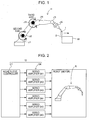
- Fig. 1 is a schematic diagram illustrating an overall structure of the welding robot R which is an articulated robot.
- the welding robot R (hereinafter simply referred to as “robot R") is, for example, a six-axis vertical articulated robot that has six joints J (J1 to J6) and performs arc welding with a welding wire 2 fed from a welding torch 1 provided on a distal-end shaft.
- the robot R performs a motion (weaving motion) of tilting the welding wire 2 at a predetermined amplitude and frequency while moving the welding torch 1 along the direction of a welding line that connects a welding start point and a welding end point.
- Such a motion of the robot R is controlled by the control device 10, and the motion is taught by the control device 10 in advance.
- Fig. 2 is a block diagram illustrating a general configuration of the control device 10 and a general configuration of servo amplifiers SA (SA1 to SA6).
- the control device 10 for the robot R mainly includes a higher-level controller C1 that controls the motion of the entire robot R, and the servo amplifiers SA (SA1 to SA6) that control the operation of the motors M (M1 to M6) for the joints J (J1 to J6) of the robot.
- the higher-level controller C1, the servo amplifiers SA, and the robot R are connected to each other by communication lines, through which information is transmitted.
- FIG. 3 is a block diagram illustrating a general configuration of the higher-level controller C1.
- the higher-level controller C1 illustrated in Fig. 3 generates command values for the servo amplifiers SA (described below) such that the robot R moves in accordance with prestored motion information (generally referred to as "teaching data") of the robot R.
- the higher-level controller C1 includes a joint-angle command calculating unit 11, an axial-force torque calculating unit 12, an elastic deformation compensation unit 13, an FF torque calculating unit 14, a stop position detecting unit 15, and a command angle switching unit 16.
- the joint-angle command calculating unit 11 calculates and outputs a joint-angle command value indicating the angle of each joint J to cause the robot R to perform a desired motion. On the basis of the prestored motion information (teaching data) of the robot R, the joint-angle command calculating unit 11 performs inverse transformation from the position of the welding torch 1 at the distal end of the robot R, thereby generating an angle command value for each joint J of the robot R (joint-angle command value ⁇ L ) as a first angle command.
- the motion information of the robot R may be the angle of each joint J of the robot R.
- the joint-angle command calculating unit 11 uses the angle of each joint J, which is the motion information, as the joint-angle command value for the joint J without changing it.
- the joint-angle command calculating unit can output the generated joint-angle command value ⁇ L to the servo amplifier SA (described below) without changing it. That is, the motor command angle ⁇ M may be simply made equal to the joint angle (arm angle) of the robot R, but due to the presence of a deflection element (elastic deformation element), such as that illustrated in Fig. 4 , at the joint J of the robot R, the motor command angle ⁇ M is not equal to ( ⁇ ) the robot joint angle in practice.
- a deflection element elastic deformation element
- Fig. 4 schematically illustrates a deflection element (elastic deformation element) at the joint J of the robot R. Since a speed reducer G between the rotating shaft of the motor M and an arm A is present as an elastic deformation element, the motor angle is not necessarily equal to the joint angle.
- the axial-force torque calculating unit 12 and the elastic deformation compensation unit 13 that perform the elastic deformation compensation will now be described.
- the axial-force torque calculating unit 12 Upon receipt of the joint-angle command value ⁇ L , which is the first angle command, the axial-force torque calculating unit 12 calculates a torque ⁇ L as a first axial force torque on the basis of a kinetic model of the robot R.
- the torque ⁇ L is generated on the joint axis of the robot R that operates in accordance with the received joint-angle command value ⁇ L .
- the axial-force torque calculating unit 12 calculates the torque ⁇ L , which is an axial force torque generated at the joint J, using the kinetic model of the robot R represented by the following equation (1), and outputs the calculated torque ⁇ L .
- the elastic deformation compensation unit 13 adds the amount of deflection in the joint J calculated from the torque ⁇ L and a spring constant representing the stiffness of the joint J of the robot R to the angle of the joint J indicated by the joint-angle command value ⁇ L received by the axial-force torque calculating unit 12 to calculate and output the motor command angle indicating the rotation angle of the motor M.
- the elastic deformation compensation unit 13 receives the torque ⁇ L from the axial-force torque calculating unit 12, determines the amount of deflection ( ⁇ L /K) in the joint J on the basis of the received torque ⁇ L as shown in the following equation (2), calculates the motor command angle ⁇ M indicating the rotation angle of the motor M using the determined amount of deflection in the joint J, and outputs the calculated motor command angle ⁇ M .
- the elastic deformation compensation unit 13 outputs and transmits, to the servo amplifier SA (described below), the motor command angle ⁇ M for the motor M of each joint J calculated by equation (2).
- the elastic deformation compensation unit 13 outputs six motor command angles ⁇ M1 to ⁇ M6 for the motors M1 to M6 of the six joints J (J1 to J6) on the first to sixth axes to the servo amplifiers SA1 to SA6 (described below).
- two-degree-of-freedom control which combines feedback (FB) control with feedforward (FF) control is used, as well as the calculation of axial force torque and the elastic deformation compensation described above.
- the feedback control refers to control performed on the basis of a comparison between a command value, such as the motor command angle ⁇ M , and a state (e.g., measured joint angle) of an object to be controlled, such as the robot R.
- the feedforward control refers to control in which a command value given by using a model of the robot R, which is an object to be controlled, is used to predict an input to the motor M for operating the robot R in accordance with the command value.
- An advantage of the two-degree-of-freedom control is that the feedforward control based on the model can compensate for a delay in feedback control that controls the robot motion according to the command value.
- the two-degree-of-freedom control can make the motor M operate in accordance with the command value. What is required here is to calculate, on the basis of the model of the robot R, an input for operating the robot R in accordance with the command value, that is, a driving torque ⁇ r of the motor M.
- the FF torque calculating unit 14 outputs and transmits, to the servo amplifier SA (described below), the FF torque ⁇ r calculated by equations (3) to (5) and required for operating each motor M in accordance with the command value. For example, if the robot R is a six-axis articulated robot having six joints J, the FF torque calculating unit 14 transmits six FF torques ⁇ r1 to ⁇ r6 for the motors M1 to M6 of the six joints J1 to J6 on the first to sixth axes to the servo amplifiers SA1 to SA6 (described below).
- Fig. 5 is a block diagram illustrating an internal configuration of the servo amplifier SA.
- the servo amplifiers SA (SA1 to SA6) illustrated in Fig. 2 each have the configuration illustrated in Fig. 5 .
- the servo amplifier SA receives the motor command angle ⁇ M and the FF torque ⁇ r , which are command values output from the higher-level controller C1, and operates the motor M in accordance with these command values.
- the servo amplifier SA includes a position/speed control unit 17 and a torque control unit 18.
- the servo amplifier SA is provided for each of the motors M (M1 to M6) on the first to sixth axes.
- the servo amplifier SA1 provided for the motor M1 receives the motor command angle ⁇ M1 and the FF torque ⁇ r1 , and operates the motor M1 in accordance with these received command values.
- the servo amplifier SA2 provided for the motor M2 receives the motor command angle ⁇ M2 and the FF torque ⁇ r2 , and operates the motor M2 in accordance with these received command values.
- the position/speed control unit 17 of the servo amplifier SA outputs a torque command indicating a torque to be generated in the motor M, in accordance with the motor command angle ⁇ M output from the higher-level controller C1.
- the position/speed control unit 17 mainly performs feedback processing, on the basis of the motor command angle ⁇ M calculated by the higher-level controller C1 and also a motor detection angle ⁇ FB and a motor detection speed d ( ⁇ FB ) detected by an angle detector, such as an encoder mounted on the motor M. Then, the position/speed control unit 17 calculates, for example, a torque for operating a joint on the third axis of the robot R in accordance with the motor command angle ⁇ M3 .
- the torque control unit 18 controls the motor M in accordance with a command value obtained by adding the FF torque ⁇ r to the torque command output from the position/speed control unit 17. Specifically, the torque control unit 18 adds the FF torque ⁇ r calculated by the higher-level controller C1 to the torque calculated by the position/speed control unit 17, and controls and operates the motor M such that a desired torque is generated.
- the configuration of the higher-level controller C1 and the servo amplifier SA described above is a basic configuration of the control device 10 that controls the motion of the robot R according to the present embodiment.
- This motion control is characterized in that (1) elastic deformation compensation is performed to compensate for deflection in the joint J, and that (2) two-degree-of-freedom control is performed, in which a torque for operating the robot R in accordance with a command value is calculated on the basis of a kinetic model of the robot R.
- control device 10 of the present embodiment can operate a complex mechanical body having a plurality of joints, such as the robot described above, in accordance with a command value, or, in other words, without vibration.
- the motion control described above is effective only when the control device 10 operates the robot R in accordance with a command value based on predetermined or prestored motion information (teaching data).
- predetermined or prestored motion information teaching data
- touch sensing is performed, in which the welding wire 2 of the welding torch 1 on the distal-end shaft of the robot R is moved until the welding wire 2 contacts the workpiece W.
- touch sensing which is a robot operation widely known among those skilled in the art
- the motion of the robot R needs to be immediately stopped at the position where the welding wire 2 contacts the workpiece W.
- the control device 10 of the present embodiment includes the stop position detecting unit 15 and the command angle switching unit 16 as illustrated in Fig. 3 . This is for the purpose of suppressing vibration of the robot R that occurs when the robot motion is abruptly stopped, even when the stop position is not determined in advance, such as in the case of touch sensing.
- the stop position detecting unit 15 detects and outputs, as a motor detection angle, the angle of the motor M when the robot R contacts the workpiece W, which is an external structure. Specifically, when the welding wire 2 of the welding torch 1 contacts the workpiece W in touch sensing or the like, the stop position detecting unit 15 detects the motor detection angle ⁇ FB (motor detection angles ⁇ FB1 to ⁇ FB6 ) at the time of detection of the workpiece contact, and records the detected motor detection angle ⁇ FB .
- the command angle switching unit 16 When the stop position detecting unit 15 outputs the angle of the motor M, the command angle switching unit 16 outputs the angle of the motor M detected by the stop position detecting unit 15 as a second angle command indicating the angle of the joint J, instead of the joint-angle command value ⁇ L output from the joint-angle command calculating unit 11. Specifically, the command angle switching unit 16 receives not only the joint-angle command value ⁇ L output by the joint-angle command calculating unit 11, but also the motor detection angle ⁇ FB detected by the stop position detecting unit 15. When workpiece contact is not detected, the command angle switching unit 16 outputs the joint-angle command value ⁇ L .
- the command angle switching unit 16 When workpiece contact is detected, the command angle switching unit 16 outputs the motor detection angle ⁇ FB , instead of the joint-angle command value ⁇ L , as the second angle command. Thus, the command angle switching unit 16 switches the joint-angle command value ⁇ L to the motor detection angle ⁇ FB .
- the joint-angle command value ⁇ L and the motor detection angle ⁇ FB output from the command angle switching unit 16 are subjected to processing performed by the axial-force torque calculating unit 12 and the elastic deformation compensation unit 13. Specifically, upon receipt of the motor detection angle ⁇ FB , which is the second angle command, the axial-force torque calculating unit 12 calculates, as a second axial force torque, the torque ⁇ L generated on the joint axis of the robot R that operates in accordance with the received motor detection angle ⁇ FB , on the basis of a kinetic model of the robot R.
- the elastic deformation compensation unit 13 adds the torque ⁇ L , which is the second axial force torque, and the amount of deflection in the joint J to the angle of the joint J indicated by the motor detection angle ⁇ FB received by the axial-force torque calculating unit 12 to calculate a motor command angle.
- the calculated motor command angle is output as the motor command angle ⁇ M to the servo amplifier SA, or is subjected to processing performed by the FF torque calculating unit 14 and output as the FF torque ⁇ r to the servo amplifier SA.
- Figs. 6A to 6D are graphs each showing how the motor M or arm on the second or third axis of the robot R behaves when the control device 10 according to the present embodiment causes touch sensing to be performed.
- Figs. 7A to 7D are graphs each showing how the motor M or arm on the second or third axis of the robot R behaves when a control device without the stop position detecting unit 15 and the command angle switching unit 16 causes touch sensing to be performed.
- Figs. 6A to 6D show that when the control device 10 of the present embodiment is used, the arm angle does not significantly change (i.e., the arm remains stationary and does not vibrate) after 3.05 seconds, which is 0.05 seconds (s) from the workpiece contact time indicated by time 3 in seconds (s), on both the second and third axes. This means that the robot R can be quickly stopped without vibration.
- Figs. 7A to 7D show that when the control device 10 without the stop position detecting unit 15 and the command angle switching unit 16 is used, the arm angle significantly changes (i.e., the arm continues to vibrate) even after 3.05 seconds. This means that the robot R cannot be quickly stopped without vibration.
- FIG. 8 is a block diagram illustrating a general configuration of a higher-level controller C2 according to the present embodiment.
- the configuration of the control device 20 according to the present embodiment differs from that of the control device 10 according to the first embodiment in that the higher-level controller C2 corresponding to the higher-level controller C1 of the first embodiment includes an inverse elastic deformation compensation unit 21.
- the configuration other than the inverse elastic deformation compensation unit 21 is the same as that of the control device 10 according to the first embodiment. Therefore, the following description refers to the inverse elastic deformation compensation unit 21 and the advantage effect of the control device 20 achieved by including the inverse elastic deformation compensation unit 21.
- the robot joint angle is replaced by the motor detection angle recorded at the time of workpiece contact. Since the motor command angle ⁇ M is not equal to ( ⁇ ) the robot joint angle as described in the first embodiment, simply replacing the joint-angle command value ⁇ L with the motor detection angle ⁇ FB causes displacement corresponding to the amount of deflection in the joint J.
- the control device 20 of the present embodiment includes the inverse elastic deformation compensation unit 21 to solve the problem of displacement of the robot stop position from the position at the time of workpiece contact.
- the stop position detecting unit 15 detects, records, and outputs the corrected motor detection angle, instead of the motor detection angle ⁇ FB , and performs the same processing as in the first embodiment.
- the command angle switching unit 16 receives both the joint-angle command value ⁇ L output by the joint-angle command calculating unit 11 and the corrected motor detection angle detected by the stop position detecting unit 15, and performs the same operation as in the first embodiment.
- a technical feature of the control device 20 according to the present embodiment is that the command angle switching unit 16 outputs the corrected motor detection angle, instead of the robot joint angle (joint-angle command value ⁇ L ).
- the corrected motor detection angle is obtained by the inverse elastic deformation compensation unit 21 by correcting the motor detection angle at the time of detection of workpiece contact.
- the elastic deformation compensation unit 13 of the present embodiment adds the amount of deflection in the joint J of the robot R to the joint angle indicated by the joint-angle command value ⁇ L received by the axial-force torque calculating unit 12, thereby compensating for the effect of elastic deformation in the robot R.
- This compensation makes it possible to suppress vibration caused by abrupt stopping of the robot R.
- the compensation performed by the elastic deformation compensation unit 13 works even after the stopping, and the robot R stops at a certain distance from the position at the time of workpiece contact.
- the inverse elastic deformation compensation unit 21 having a feature completely opposite the feature of the elastic deformation compensation unit 13 is prepared.
- the corrected motor detection angle obtained by correction performed by the inverse elastic deformation compensation unit 21, instead of the robot joint angle, is output from the command angle switching unit 16 to cancel out the compensation made by the elastic deformation compensation unit 13 after stopping of the robot R.
- the control device 20 of the present embodiment can quickly and accurately stop the robot R at a desired stop position (near the position at the time of workpiece contact) without causing the robot R to vibrate, in a motion which requires the robot R to be quickly stopped at a position not determined in advance, such as a robot motion for creating teaching data. It is thus possible to solve the problem of displacement of the robot stop position from the position at the time of workpiece contact.
- FIGs. 9A to 9D are graphs each showing how the motor M or arm on the second or third axis of the robot R behaves when the control device 20 according to the present embodiment causes touch sensing to be performed.
- Figs. 9A to 9D show that when the control device 20 of the present embodiment is used, the arm angle does not significantly change (i.e., the arm remains stationary and does not vibrate) after 3.05 seconds, which is 0.05 seconds (s) from the workpiece contact time indicated by time 3 in seconds (s), on both the second and third axes. This means that the robot R can be quickly stopped without vibration. Additionally, the robot stop position is substantially equal to the position at the time of workpiece contact indicated by a solid line. This means that there is little displacement of the robot stop position from the position at the time of workpiece contact.
Abstract
Description
- The present invention relates to a robot control device.
- An industrial robot is an example of a robot whose position is determined by varying its joint angle. Examples of a welding operation using a welding robot, which is a type of industrial robot, include an operation called touch sensing that senses the position of a workpiece to be welded. Touch sensing is a sensing operation which involves moving a welding robot while applying a voltage to a welding torch, and detecting a position at which a welding wire of the welding torch contacts the workpiece (i.e., a position at which electrical conduction between the workpiece and the welding wire is detected) as a workpiece position.
- The touch sensing normally detects the position of the workpiece on the basis of the position of the robot (i.e., the motor angle for each joint of the robot) when the contact with the workpiece is detected. However, there is a delay between detection of the contact with the workpiece and acquisition of information about the position of the robot. If the welding wire is moved at a high speed and brought into contact with the workpiece, the welding wire is significantly moved even during the delay time. As a result, a position which is displaced from the actual workpiece position is detected as the position of the workpiece.
- Therefore, when the welding wire is brought close to the workpiece, the welding robot is operated at a low speed to allow the welding wire to move at a low speed. However, operating the welding robot at a low speed is disadvantageous in that it takes time to perform the sensing.
- As solutions to the problems described above, Patent Literature (PTL) 1 discloses a workpiece detecting method for an automatic welding apparatus, and
PTL 2 discloses a wire touch sensing method for a welding robot. - The workpiece detecting method disclosed in
PTL 1 is a workpiece detecting method for an automatic welding apparatus. The automatic welding apparatus includes conduction detecting means for selectively applying a welding voltage and a sensing voltage to a consumable electrode type welding torch, and detecting, during application of the sensing voltage, a state of electrical conduction between a consumable electrode protruding from the welding torch and a workpiece. The workpiece detecting method includes bringing the welding torch close to the workpiece at a high speed while applying the sensing voltage to the welding torch, stopping the motion of the welding torch in response to a conduction detection output from the conduction detecting means, detaching the welding torch at a low speed in accordance with the conduction detection output, detecting by the conduction detecting means the detachment of the consumable electrode from the workpiece, and using a detachment detection output from the conduction detecting means as a control signal for the automatic welding apparatus. - The wire touch sensing method disclosed in
PTL 2 includes moving a welding wire while applying a voltage thereto, moving the wire backward at a low speed upon detection of a signal indicating a short circuit in the wire, and determining the position of detecting a short-circuit cancellation signal as a position at which an object to be welded is actually located. - In the techniques disclosed in these patent literatures, the welding wire is brought into contact with the workpiece while a voltage is applied to the welding torch, and the robot is stopped after detection of contact with the workpiece. Then, the welding wire is moved at a low speed to be detached from the workpiece, and the position of the workpiece is detected on the basis of the robot position when the welding wire and the workpiece are brought out of conduction.
- In this method, after the welding wire is brought close to the workpiece at a high speed and then temporarily stopped, the workpiece position is detected during the subsequent detachment motion. Thus, the workpiece position can be accurately detected in a short sensing time.
- As a technique for stopping the welding wire that has been brought close to the workpiece at a high speed,
PTL 3 discloses an acceleration/deceleration method for an industrial machine. - The acceleration/deceleration method disclosed in
PTL 3 is an industrial machine acceleration/deceleration method for controlling acceleration and deceleration of moving means in an industrial machine. The industrial machine includes a machine base whose relationship with an installation location is approximated to a first spring vibration system; and a control object having the moving means whose relationship with the machine base is approximated to a second spring vibration system, the moving means being configured to move over the machine base in response to a force generated by motion of an actuator secured onto the machine base. To accelerate and decelerate the moving means with a constant acceleration, a velocity command is generated which makes the acceleration time and the deceleration time equal to a period which is an integral multiple of the natural vibration period of the machine base determined on the basis of the sum of the masses of the machine base and the actuator and the spring constant of the first spring vibration system, and a motion command that causes the moving means to move on the basis of the velocity command is output to the actuator. - By generating a deceleration path using the acceleration/deceleration method based on the natural vibration period, the industrial machine can be stopped without vibration.
-
- PTL 1: Japanese Unexamined Patent Application Publication No.
1-249268 - PTL 2: Japanese Unexamined Patent Application Publication No.
7-308780 - PTL 3: Japanese Unexamined Patent Application Publication No.
2001-290541 - If the robot is simply abruptly stopped upon contact of the welding wire with the workpiece as in the techniques disclosed in
PTLs - As a solution to this problem, the technique disclosed in
PTL 3 may be used, in which the robot is stopped without vibration. However, the technique disclosed inPTL 3 is a technique applicable to the case where a stop position for stopping the robot is determined in advance. That is, if the stop position is determined in advance, a deceleration path can be generated toward the stop position. However, the deceleration path cannot be generated if the stop position is not determined in advance, as in the case of the wire touch sensing in which the stop position is determined upon contact with the workpiece. - Additionally, in the case of an apparatus having a plurality of joints, such as a welding robot, vibration generated at each joint is transmitted to other joints and becomes very complex. That is, the vibration cannot be suppressed simply by taking into account the natural vibration period. Therefore, even when the technique disclosed in
PTL 3 is applied to the wire touch sensing, it is not possible to suppress vibration generated when the robot is stopped. - The present invention has been made in view of the problems described above. An object of the present invention is to provide a robot control device that can quickly stop a robot at a desired position while suppressing vibration of the robot.
- To solve the problems described above, a robot control device according to the present invention takes the following technical measures. That is, a robot control device according to the present invention is a control device that controls an angle of a joint of a robot driven by a motor. The robot control device includes a joint-angle command calculating unit configured to calculate and output a first angle command indicating an angle of the joint for causing the robot to perform a desired motion; an axial-force torque calculating unit configured to calculate, upon receipt of the first angle command, a first axial force torque on the basis of a kinetic model of the robot, the first axial force torque being generated on a joint axis of the robot operating in accordance with the received first angle command; an elastic deformation compensation unit configured to add the amount of deflection in the joint calculated from the first axial force torque and a spring constant representing stiffness of the joint of the robot to the angle of the joint indicated by the first angle command received by the axial-force torque calculating unit, to calculate and output a motor command angle indicating a rotation angle of the motor; a stop position detecting unit configured to detect and output, as a motor detection angle, an angle of the motor when the robot contacts an external structure; and a command angle switching unit configured to output, when the stop position detecting unit outputs the angle of the motor, the angle of the motor detected by the stop position detecting unit as a second angle command indicating the angle of the joint, instead of the first angle command output from the joint-angle command calculating unit.
- Upon receipt of the second angle command, the axial-force torque calculating unit may calculate a second axial force torque on the basis of the kinetic model of the robot, the second axial force torque being generated on the joint axis of the robot operating in accordance with the received second angle command. The elastic deformation compensation unit may add the second axial force torque and the amount of deflection in the joint to the angle of the joint indicated by the second angle command received by the axial-force torque calculating unit to calculate the motor command angle.
- The robot control device may further include an inverse elastic deformation compensation unit configured to subtract, from the motor detection angle, the amount of deflection in the joint calculated from the first or second axial force torque output from the axial-force torque calculating unit and the spring constant representing stiffness of the joint to calculate a corrected motor detection angle. The stop position detecting unit may detect and output the corrected motor detection angle, instead of the motor detection angle.
- The robot control device may further include an FF torque calculating unit configured to calculate, upon receipt of the first angle command, an FF torque on the basis of kinetic models of the robot and the motor, the FF torque being generated in the motor when the joint operates in accordance with the first angle command; a position/speed control unit configured to output, in accordance with the output motor command angle, a torque command indicating a torque to be generated in the motor; and a torque control unit configured to control the motor in accordance with a command value obtained by adding the FF torque to the torque command output from the position/speed control unit.
- By using the robot control device according to the present invention, it is possible to quickly stop the robot at a desired position while suppressing vibration of the robot. Brief Description of Drawings
- [
Fig. 1] Fig. 1 is a schematic diagram illustrating an overall structure of a welding robot which is an articulated robot according to an embodiment of the present invention. - [
Fig. 2] Fig. 2 is a block diagram illustrating a general configuration of a control device according to an embodiment of the present invention. - [
Fig. 3] Fig. 3 is a block diagram illustrating a general configuration of a higher-level controller according to a first embodiment of the present invention. - [
Fig. 4] Fig. 4 schematically illustrates a deflection element (elastic deformation element) at a joint of a robot according to the present embodiment. - [
Fig. 5] Fig. 5 is a block diagram illustrating a general configuration of a servo amplifier according to the present embodiment. - [
Fig. 6A] Fig. 6A is a graph showing how a motor on a second axis of the robot behaves when a control device according to the present embodiment (first embodiment) causes touch sensing to be performed. - [
Fig. 6B] Fig. 6B is a graph showing how an arm on the second axis of the robot behaves when the control device according to the present embodiment (first embodiment) causes touch sensing to be performed. - [
Fig. 6C] Fig. 6C is a graph showing how a motor on a third axis of the robot behaves when the control device according to the present embodiment (first embodiment) causes touch sensing to be performed. - [
Fig. 6D] Fig. 6D is a graph showing how an arm on the third axis of the robot behaves when the control device according to the present embodiment (first embodiment) causes touch sensing to be performed. - [
Fig. 7A] Fig. 7A is a graph showing how the motor on the second axis of the robot behaves when a control device without a stop position detecting unit and a command angle switching unit causes touch sensing to be performed. - [
Fig. 7B] Fig. 7B is a graph showing how the arm on the second axis of the robot behaves when the control device without the stop position detecting unit and the command angle switching unit causes touch sensing to be performed. - [
Fig. 7C] Fig. 7C is a graph showing how the motor on the third axis of the robot behaves when the control device without the stop position detecting unit and the command angle switching unit causes touch sensing to be performed. - [
Fig. 7D] Fig. 7D is a graph showing how the arm on the third axis of the robot behaves when the control device without the stop position detecting unit and the command angle switching unit causes touch sensing to be performed. - [
Fig. 8] Fig. 8 is a block diagram illustrating a general configuration of a higher-level controller according to a second embodiment of the present invention. - [
Fig. 9A] Fig. 9A is a graph showing how the motor on the second axis of the robot behaves when a control device according to the present embodiment (second embodiment) causes touch sensing to be performed. - [
Fig. 9B] Fig. 9B is a graph showing how the arm on the second axis of the robot behaves when the control device according to the present embodiment (second embodiment) causes touch sensing to be performed. - [
Fig. 9C] Fig. 9C is a graph showing how the motor on the third axis of the robot behaves when the control device according to the present embodiment (second embodiment) causes touch sensing to be performed. - [
Fig. 9D] Fig. 9D is a graph showing how the arm on the third axis of the robot behaves when the control device according to the present embodiment (second embodiment) causes touch sensing to be performed. - Hereinafter, a robot control device according to an embodiment of the present invention will be described in detail on the basis of the drawings.
- The same components common to the embodiments described below are assigned the same reference numerals and names. Accordingly, the description of the components assigned the same reference numerals and names will not be repeated.
- With reference to
Figs. 1 to 6 andFigs. 7A to 7D , acontrol device 10 for controlling a robot R according to a first embodiment of the present invention will be described. - First, how the
control device 10 of the present embodiment generally controls the robot R will be described. The robot R controlled by thecontrol device 10 of the present embodiment is a robot that has at least one joint J, and operates (or changes its position) when the angle of the joint J is changed by driving (rotating) a motor M. Thecontrol device 10 operates the robot R by controlling the rotation of the motor M to change the angle of the joint. - The present embodiment illustrates an articulated welding robot R as the robot R whose motion is controlled by the
control device 10. -
Fig. 1 is a schematic diagram illustrating an overall structure of the welding robot R which is an articulated robot. The welding robot R (hereinafter simply referred to as "robot R") is, for example, a six-axis vertical articulated robot that has six joints J (J1 to J6) and performs arc welding with awelding wire 2 fed from awelding torch 1 provided on a distal-end shaft. For example, the robot R performs a motion (weaving motion) of tilting thewelding wire 2 at a predetermined amplitude and frequency while moving thewelding torch 1 along the direction of a welding line that connects a welding start point and a welding end point. Such a motion of the robot R is controlled by thecontrol device 10, and the motion is taught by thecontrol device 10 in advance. -
Fig. 2 is a block diagram illustrating a general configuration of thecontrol device 10 and a general configuration of servo amplifiers SA (SA1 to SA6). As illustrated inFig. 2 , thecontrol device 10 for the robot R mainly includes a higher-level controller C1 that controls the motion of the entire robot R, and the servo amplifiers SA (SA1 to SA6) that control the operation of the motors M (M1 to M6) for the joints J (J1 to J6) of the robot. The higher-level controller C1, the servo amplifiers SA, and the robot R are connected to each other by communication lines, through which information is transmitted. - With reference to
Figs. 3 and 4 , the higher-level controller C1 and the servo amplifiers SA (SA1 to SA6) will be described.Fig. 3 is a block diagram illustrating a general configuration of the higher-level controller C1. - The higher-level controller C1 illustrated in
Fig. 3 generates command values for the servo amplifiers SA (described below) such that the robot R moves in accordance with prestored motion information (generally referred to as "teaching data") of the robot R. The higher-level controller C1 includes a joint-anglecommand calculating unit 11, an axial-forcetorque calculating unit 12, an elasticdeformation compensation unit 13, an FFtorque calculating unit 14, a stopposition detecting unit 15, and a commandangle switching unit 16. - The joint-angle
command calculating unit 11 calculates and outputs a joint-angle command value indicating the angle of each joint J to cause the robot R to perform a desired motion. On the basis of the prestored motion information (teaching data) of the robot R, the joint-anglecommand calculating unit 11 performs inverse transformation from the position of thewelding torch 1 at the distal end of the robot R, thereby generating an angle command value for each joint J of the robot R (joint-angle command value θL) as a first angle command. The motion information of the robot R may be the angle of each joint J of the robot R. In this case, the joint-anglecommand calculating unit 11 uses the angle of each joint J, which is the motion information, as the joint-angle command value for the joint J without changing it. - As a motor command angle θM, which is a command angle for moving the motor M, the joint-angle command calculating unit can output the generated joint-angle command value θL to the servo amplifier SA (described below) without changing it. That is, the motor command angle θM may be simply made equal to the joint angle (arm angle) of the robot R, but due to the presence of a deflection element (elastic deformation element), such as that illustrated in
Fig. 4 , at the joint J of the robot R, the motor command angle θM is not equal to (≠) the robot joint angle in practice. For accurate motion of the robot R, compensation is performed to compensate for error caused by deflection (elastic deformation). This compensation is referred to as elastic deformation compensation. -
Fig. 4 schematically illustrates a deflection element (elastic deformation element) at the joint J of the robot R. Since a speed reducer G between the rotating shaft of the motor M and an arm A is present as an elastic deformation element, the motor angle is not necessarily equal to the joint angle. - The axial-force
torque calculating unit 12 and the elasticdeformation compensation unit 13 that perform the elastic deformation compensation will now be described. - Upon receipt of the joint-angle command value θL, which is the first angle command, the axial-force
torque calculating unit 12 calculates a torque τL as a first axial force torque on the basis of a kinetic model of the robot R. The torque τL is generated on the joint axis of the robot R that operates in accordance with the received joint-angle command value θL. Specifically, from the joint-angle command value θL for the robot R, the axial-forcetorque calculating unit 12 calculates the torque τL, which is an axial force torque generated at the joint J, using the kinetic model of the robot R represented by the following equation (1), and outputs the calculated torque τL.
[Equation 1]
- θL: robot joint-angle command value
- J(θL )·θ̈L : inertial force on arm
- C(θL ,θ̇L ): centrifugal and Coriolis forces on arm
- G(θL) : gravity on arm
- FM (θ̇L ) : frictional force on arm
- The elastic
deformation compensation unit 13 adds the amount of deflection in the joint J calculated from the torque τL and a spring constant representing the stiffness of the joint J of the robot R to the angle of the joint J indicated by the joint-angle command value θL received by the axial-forcetorque calculating unit 12 to calculate and output the motor command angle indicating the rotation angle of the motor M. Specifically, the elasticdeformation compensation unit 13 receives the torque τL from the axial-forcetorque calculating unit 12, determines the amount of deflection (τL/K) in the joint J on the basis of the received torque τL as shown in the following equation (2), calculates the motor command angle θM indicating the rotation angle of the motor M using the determined amount of deflection in the joint J, and outputs the calculated motor command angle θM.
[Equation 2]
- θM: motor command angle
- K: spring constant related to deflection in joint
- The elastic
deformation compensation unit 13 outputs and transmits, to the servo amplifier SA (described below), the motor command angle θM for the motor M of each joint J calculated by equation (2). For example, if the robot R is a six-axis articulated robot having six joints J, the elasticdeformation compensation unit 13 outputs six motor command angles θM1 to θM6 for the motors M1 to M6 of the six joints J (J1 to J6) on the first to sixth axes to the servo amplifiers SA1 to SA6 (described below). - For accurate motion of the robot R, two-degree-of-freedom control which combines feedback (FB) control with feedforward (FF) control is used, as well as the calculation of axial force torque and the elastic deformation compensation described above. The feedback control refers to control performed on the basis of a comparison between a command value, such as the motor command angle θM, and a state (e.g., measured joint angle) of an object to be controlled, such as the robot R. The feedforward control refers to control in which a command value given by using a model of the robot R, which is an object to be controlled, is used to predict an input to the motor M for operating the robot R in accordance with the command value.
- An advantage of the two-degree-of-freedom control is that the feedforward control based on the model can compensate for a delay in feedback control that controls the robot motion according to the command value. The two-degree-of-freedom control can make the motor M operate in accordance with the command value. What is required here is to calculate, on the basis of the model of the robot R, an input for operating the robot R in accordance with the command value, that is, a driving torque τr of the motor M.
- Upon receipt of the joint-angle command value θL, which is the first angle command, the FF
torque calculating unit 14 calculates, on the basis of kinetic models of the robot R and the motor M, an FF torque generated in the motor M when the robot R operates in accordance with the calculated joint-angle command value θL. Specifically, on the basis of the kinetic model of the robot R and the kinetic model of the motor M, the FFtorque calculating unit 14 calculates the driving torque τr (referred to as "FF torque τr") of the motor M for operating the robot R in accordance with the command value by using, for example, the following equations (3) to (5) and outputs the calculated FF torque τr.
[Equation 3]
- θL: robot joint-angle command value
- J(θL )·θ̈L : inertial force on arm
- C(θL ,θ̇L ): centrifugal and Coriolis forces on arm
- G(θL): gravity on arm
- FM (θ̇L ): frictional force on arm
- θM: motor command angle
- JM·θ̈M : inertial force on motor
- FM (θ̇M ): frictional force on arm
- The FF
torque calculating unit 14 outputs and transmits, to the servo amplifier SA (described below), the FF torque τr calculated by equations (3) to (5) and required for operating each motor M in accordance with the command value. For example, if the robot R is a six-axis articulated robot having six joints J, the FFtorque calculating unit 14 transmits six FF torques τr1 to τr6 for the motors M1 to M6 of the six joints J1 to J6 on the first to sixth axes to the servo amplifiers SA1 to SA6 (described below). - The servo amplifier SA will now be described with reference to
Figs. 2 and5. Fig. 5 is a block diagram illustrating an internal configuration of the servo amplifier SA. The servo amplifiers SA (SA1 to SA6) illustrated inFig. 2 each have the configuration illustrated inFig. 5 . - The servo amplifier SA receives the motor command angle θM and the FF torque τr, which are command values output from the higher-level controller C1, and operates the motor M in accordance with these command values. The servo amplifier SA includes a position/
speed control unit 17 and atorque control unit 18. The servo amplifier SA is provided for each of the motors M (M1 to M6) on the first to sixth axes. For example, the servo amplifier SA1 provided for the motor M1 receives the motor command angle θM1 and the FF torque τr1, and operates the motor M1 in accordance with these received command values. Similarly, the servo amplifier SA2 provided for the motor M2 receives the motor command angle θM2 and the FF torque τr2, and operates the motor M2 in accordance with these received command values. - The position/
speed control unit 17 of the servo amplifier SA outputs a torque command indicating a torque to be generated in the motor M, in accordance with the motor command angle θM output from the higher-level controller C1. Specifically, the position/speed control unit 17 mainly performs feedback processing, on the basis of the motor command angle θM calculated by the higher-level controller C1 and also a motor detection angle θFB and a motor detection speed d (θFB) detected by an angle detector, such as an encoder mounted on the motor M. Then, the position/speed control unit 17 calculates, for example, a torque for operating a joint on the third axis of the robot R in accordance with the motor command angle θM3. - The
torque control unit 18 controls the motor M in accordance with a command value obtained by adding the FF torque τr to the torque command output from the position/speed control unit 17. Specifically, thetorque control unit 18 adds the FF torque τr calculated by the higher-level controller C1 to the torque calculated by the position/speed control unit 17, and controls and operates the motor M such that a desired torque is generated. - The configuration of the higher-level controller C1 and the servo amplifier SA described above is a basic configuration of the
control device 10 that controls the motion of the robot R according to the present embodiment. This motion control is characterized in that (1) elastic deformation compensation is performed to compensate for deflection in the joint J, and that (2) two-degree-of-freedom control is performed, in which a torque for operating the robot R in accordance with a command value is calculated on the basis of a kinetic model of the robot R. - With the two motion control operations described above, the
control device 10 of the present embodiment can operate a complex mechanical body having a plurality of joints, such as the robot described above, in accordance with a command value, or, in other words, without vibration. - The motion control described above is effective only when the
control device 10 operates the robot R in accordance with a command value based on predetermined or prestored motion information (teaching data). In a robot motion performed when there is no prestored motion information (teaching data) of the robot R and motion information (teaching data) is to be newly created, it is difficult for thecontrol device 10 to operate, with only the configuration described above, the robot R in accordance with a command value. - Specifically, for the purpose of identifying the position and shape of a workpiece W (see
Fig. 1 ) in the process of creating teaching data for a welding robot or the like, touch sensing is performed, in which thewelding wire 2 of thewelding torch 1 on the distal-end shaft of the robot R is moved until thewelding wire 2 contacts the workpiece W. In the touch sensing, which is a robot operation widely known among those skilled in the art, the motion of the robot R needs to be immediately stopped at the position where thewelding wire 2 contacts the workpiece W. When the robot R is thus abruptly stopped at a position not determined in advance, elastic deformation of the joint J causes the entire robot R to vibrate, particularly in the vicinity of the distal-end shaft on which thewelding torch 1 is provided. - The
control device 10 of the present embodiment includes the stopposition detecting unit 15 and the commandangle switching unit 16 as illustrated inFig. 3 . This is for the purpose of suppressing vibration of the robot R that occurs when the robot motion is abruptly stopped, even when the stop position is not determined in advance, such as in the case of touch sensing. - The stop
position detecting unit 15 detects and outputs, as a motor detection angle, the angle of the motor M when the robot R contacts the workpiece W, which is an external structure. Specifically, when thewelding wire 2 of thewelding torch 1 contacts the workpiece W in touch sensing or the like, the stopposition detecting unit 15 detects the motor detection angle θFB (motor detection angles θFB1 to θFB6) at the time of detection of the workpiece contact, and records the detected motor detection angle θFB. - When the stop
position detecting unit 15 outputs the angle of the motor M, the commandangle switching unit 16 outputs the angle of the motor M detected by the stopposition detecting unit 15 as a second angle command indicating the angle of the joint J, instead of the joint-angle command value θL output from the joint-anglecommand calculating unit 11. Specifically, the commandangle switching unit 16 receives not only the joint-angle command value θL output by the joint-anglecommand calculating unit 11, but also the motor detection angle θFB detected by the stopposition detecting unit 15. When workpiece contact is not detected, the commandangle switching unit 16 outputs the joint-angle command value θL. When workpiece contact is detected, the commandangle switching unit 16 outputs the motor detection angle θFB, instead of the joint-angle command value θL, as the second angle command. Thus, the commandangle switching unit 16 switches the joint-angle command value θL to the motor detection angle θFB. - The joint-angle command value θL and the motor detection angle θFB output from the command
angle switching unit 16 are subjected to processing performed by the axial-forcetorque calculating unit 12 and the elasticdeformation compensation unit 13. Specifically, upon receipt of the motor detection angle θFB, which is the second angle command, the axial-forcetorque calculating unit 12 calculates, as a second axial force torque, the torque τL generated on the joint axis of the robot R that operates in accordance with the received motor detection angle θFB, on the basis of a kinetic model of the robot R. Then, the elasticdeformation compensation unit 13 adds the torque τL, which is the second axial force torque, and the amount of deflection in the joint J to the angle of the joint J indicated by the motor detection angle θFB received by the axial-forcetorque calculating unit 12 to calculate a motor command angle. The calculated motor command angle is output as the motor command angle θM to the servo amplifier SA, or is subjected to processing performed by the FFtorque calculating unit 14 and output as the FF torque τr to the servo amplifier SA. - By controlling the motion of the robot R with the
control device 10 including the higher-level controller C1 and the servo amplifier SA described above, it is possible to quickly stop the robot R without causing the robot R to vibrate in a motion which requires the robot R to be quickly stopped at a position not determined in advance, such as a robot motion for creating teaching data. - With reference to
Figs. 6A to 6D andFigs. 7A to 7D , an advantageous effect of thecontrol device 10 according to the present embodiment will be described.Figs. 6A to 6D are graphs each showing how the motor M or arm on the second or third axis of the robot R behaves when thecontrol device 10 according to the present embodiment causes touch sensing to be performed.Figs. 7A to 7D are graphs each showing how the motor M or arm on the second or third axis of the robot R behaves when a control device without the stopposition detecting unit 15 and the commandangle switching unit 16 causes touch sensing to be performed. -
Figs. 6A to 6D show that when thecontrol device 10 of the present embodiment is used, the arm angle does not significantly change (i.e., the arm remains stationary and does not vibrate) after 3.05 seconds, which is 0.05 seconds (s) from the workpiece contact time indicated bytime 3 in seconds (s), on both the second and third axes. This means that the robot R can be quickly stopped without vibration. - On the other hand,
Figs. 7A to 7D show that when thecontrol device 10 without the stopposition detecting unit 15 and the commandangle switching unit 16 is used, the arm angle significantly changes (i.e., the arm continues to vibrate) even after 3.05 seconds. This means that the robot R cannot be quickly stopped without vibration. - With reference to
Fig. 8 andFigs. 9A to 9D , acontrol device 20 for the robot R according to a second embodiment of the present invention will be described.Fig. 8 is a block diagram illustrating a general configuration of a higher-level controller C2 according to the present embodiment. - The configuration of the
control device 20 according to the present embodiment differs from that of thecontrol device 10 according to the first embodiment in that the higher-level controller C2 corresponding to the higher-level controller C1 of the first embodiment includes an inverse elasticdeformation compensation unit 21. The configuration other than the inverse elasticdeformation compensation unit 21 is the same as that of thecontrol device 10 according to the first embodiment. Therefore, the following description refers to the inverse elasticdeformation compensation unit 21 and the advantage effect of thecontrol device 20 achieved by including the inverse elasticdeformation compensation unit 21. - Referring to
Figs. 6A to 6D described in the first embodiment, vibration caused by abrupt stopping is successfully suppressed on both the second and third axes. However, the arm angle after 3.05 seconds, that is, the robot stop position, is substantially away from the position at the time of workpiece contact indicated by a solid line. This is because the commandangle switching unit 16 simply replaces the joint-angle command value θL with the motor detection angle θFB recorded at the time of workpiece contact. - That is, the robot joint angle is replaced by the motor detection angle recorded at the time of workpiece contact. Since the motor command angle θM is not equal to (≠) the robot joint angle as described in the first embodiment, simply replacing the joint-angle command value θL with the motor detection angle θFB causes displacement corresponding to the amount of deflection in the joint J.
- The
control device 20 of the present embodiment includes the inverse elasticdeformation compensation unit 21 to solve the problem of displacement of the robot stop position from the position at the time of workpiece contact. - The inverse elastic
deformation compensation unit 21 subtracts, from the motor detection angle θFB, the amount of deflection in the joint calculated from the torque τL (first axial force torque or second axial force torque) output from the axial-forcetorque calculating unit 12 and a spring constant representing stiffness of the joint to calculate a corrected motor detection angle. Specifically, on the basis of the torque τL calculated by the axial-forcetorque calculating unit 12, the inverse elasticdeformation compensation unit 21 corrects (subtracts) the motor detection angle θFB as indicated by the following equation (6) to newly create a corrected motor detection angle, and output it to the stopposition detecting unit 15.
[Equation 6]
- θ̃ FB: corrected motor detection angle
- θFB: motor detection angle
- K: spring constant related to deflection in joint
- Then the stop
position detecting unit 15 detects, records, and outputs the corrected motor detection angle, instead of the motor detection angle θFB, and performs the same processing as in the first embodiment. The commandangle switching unit 16 receives both the joint-angle command value θL output by the joint-anglecommand calculating unit 11 and the corrected motor detection angle detected by the stopposition detecting unit 15, and performs the same operation as in the first embodiment. - A technical feature of the
control device 20 according to the present embodiment is that the commandangle switching unit 16 outputs the corrected motor detection angle, instead of the robot joint angle (joint-angle command value θL). The corrected motor detection angle is obtained by the inverse elasticdeformation compensation unit 21 by correcting the motor detection angle at the time of detection of workpiece contact. - That is, as described above, the elastic
deformation compensation unit 13 of the present embodiment adds the amount of deflection in the joint J of the robot R to the joint angle indicated by the joint-angle command value θL received by the axial-forcetorque calculating unit 12, thereby compensating for the effect of elastic deformation in the robot R. This compensation makes it possible to suppress vibration caused by abrupt stopping of the robot R. However, the compensation performed by the elasticdeformation compensation unit 13 works even after the stopping, and the robot R stops at a certain distance from the position at the time of workpiece contact. - Accordingly, the inverse elastic
deformation compensation unit 21 having a feature completely opposite the feature of the elasticdeformation compensation unit 13 is prepared. Thus, the corrected motor detection angle obtained by correction performed by the inverse elasticdeformation compensation unit 21, instead of the robot joint angle, is output from the commandangle switching unit 16 to cancel out the compensation made by the elasticdeformation compensation unit 13 after stopping of the robot R. - Therefore, by controlling the motion of the robot R with the higher-level controller C2 including the inverse elastic
deformation compensation unit 21, thecontrol device 20 of the present embodiment can quickly and accurately stop the robot R at a desired stop position (near the position at the time of workpiece contact) without causing the robot R to vibrate, in a motion which requires the robot R to be quickly stopped at a position not determined in advance, such as a robot motion for creating teaching data. It is thus possible to solve the problem of displacement of the robot stop position from the position at the time of workpiece contact. - With reference to
Figs. 9A to 9D , an advantageous effect of thecontrol device 20 according to the present embodiment will be described.Figs. 9A to 9D are graphs each showing how the motor M or arm on the second or third axis of the robot R behaves when thecontrol device 20 according to the present embodiment causes touch sensing to be performed. -
Figs. 9A to 9D show that when thecontrol device 20 of the present embodiment is used, the arm angle does not significantly change (i.e., the arm remains stationary and does not vibrate) after 3.05 seconds, which is 0.05 seconds (s) from the workpiece contact time indicated bytime 3 in seconds (s), on both the second and third axes. This means that the robot R can be quickly stopped without vibration. Additionally, the robot stop position is substantially equal to the position at the time of workpiece contact indicated by a solid line. This means that there is little displacement of the robot stop position from the position at the time of workpiece contact. - The embodiments disclosed herein are illustrative in all respects, and should not be considered restrictive. The scope of the present invention is defined by the appended claims, not by the foregoing description, and is intended to include meanings equivalent to the appended claims and all modifications within the scope. Particularly, in the embodiments disclosed herein, matters that are not explicitly disclosed, such as operating conditions, various parameters, and dimensions, weights, and volumes of components, are given by values that are within ranges generally employed by those skilled in the art and that can be easily conceived by those skilled in the art.
- The present application is based on Japanese Patent Application No.
2014-114086 filed on June 2, 2014 - 10,
- 20: control device
- 11:
- joint-angle command calculating unit
- 12:
- axial-force torque calculating unit
- 13:
- elastic deformation compensation unit
- 14:
- FF torque calculating unit
- 15:
- stop position detecting unit
- 16:
- command angle switching unit
- 17:
- position/speed control unit
- 18:
- torque control unit
- 21:
- inverse elastic deformation compensation unit
- J:
- joint
- M:
- motor
- R:
- welding robot (robot)
- W:
- workpiece (external structure)
- C1, C2:
- higher-level controller
- SA:
- servo amplifier
Claims (4)
- A robot control device that controls an angle of a joint of a robot driven by a motor, the robot control device comprising:a joint-angle command calculating unit configured to calculate and output a first angle command indicating an angle of the joint for causing the robot to perform a desired motion;an axial-force torque calculating unit configured to calculate, upon receipt of the first angle command, a first axial force torque on the basis of a kinetic model of the robot, the first axial force torque being generated on a joint axis of the robot operating in accordance with the received first angle command;an elastic deformation compensation unit configured to add the amount of deflection in the joint calculated from the first axial force torque and a spring constant representing stiffness of the joint of the robot to the angle of the joint indicated by the first angle command received by the axial-force torque calculating unit, to calculate and output a motor command angle indicating a rotation angle of the motor;a stop position detecting unit configured to detect and output, as a motor detection angle, an angle of the motor when the robot contacts an external structure; anda command angle switching unit configured to output, when the stop position detecting unit outputs the angle of the motor, the angle of the motor detected by the stop position detecting unit as a second angle command indicating the angle of the joint, instead of the first angle command output from the joint-angle command calculating unit.
- The robot control device according to Claim 1, wherein, upon receipt of the second angle command, the axial-force torque calculating unit calculates a second axial force torque on the basis of the kinetic model of the robot, the second axial force torque being generated on the joint axis of the robot operating in accordance with the received second angle command; and
the elastic deformation compensation unit adds the second axial force torque and the amount of deflection in the joint to the angle of the joint indicated by the second angle command received by the axial-force torque calculating unit to calculate the motor command angle. - The robot control device according to Claim 2, further comprising an inverse elastic deformation compensation unit configured to subtract, from the motor detection angle, the amount of deflection in the joint calculated from the first or second axial force torque output from the axial-force torque calculating unit and the spring constant representing stiffness of the joint to calculate a corrected motor detection angle,
wherein the stop position detecting unit detects and outputs the corrected motor detection angle, instead of the motor detection angle. - The robot control device according to any one of Claims 1 to 3, further comprising:an FF torque calculating unit configured to calculate, upon receipt of the first angle command, an FF torque on the basis of kinetic models of the robot and the motor, the FF torque being generated in the motor when the joint operates in accordance with the first angle command;a position/speed control unit configured to output, in accordance with the output motor command angle, a torque command indicating a torque to be generated in the motor; anda torque control unit configured to control the motor in accordance with a command value obtained by adding the FF torque to the torque command output from the position/speed control unit.
Applications Claiming Priority (2)
| Application Number | Priority Date | Filing Date | Title |
|---|---|---|---|
| JP2014114086A JP5897644B2 (en) | 2014-06-02 | 2014-06-02 | Robot control device |
| PCT/JP2015/065108 WO2015186572A1 (en) | 2014-06-02 | 2015-05-26 | Robot control device |
Publications (3)
| Publication Number | Publication Date |
|---|---|
| EP3150341A1 true EP3150341A1 (en) | 2017-04-05 |
| EP3150341A4 EP3150341A4 (en) | 2017-12-27 |
| EP3150341B1 EP3150341B1 (en) | 2020-10-07 |
Family
ID=54766645
Family Applications (1)
| Application Number | Title | Priority Date | Filing Date |
|---|---|---|---|
| EP15803269.8A Active EP3150341B1 (en) | 2014-06-02 | 2015-05-26 | Robot control device |
Country Status (6)
| Country | Link |
|---|---|
| US (1) | US10022866B2 (en) |
| EP (1) | EP3150341B1 (en) |
| JP (1) | JP5897644B2 (en) |
| KR (1) | KR101864062B1 (en) |
| CN (1) | CN106457560B (en) |
| WO (1) | WO2015186572A1 (en) |
Cited By (2)
| Publication number | Priority date | Publication date | Assignee | Title |
|---|---|---|---|---|
| DE102018101271B4 (en) | 2017-01-26 | 2019-06-06 | Fanuc Corporation | Robot program modification device, robot control device, robot simulation device, and robot program modification method |
| DE102018124007B4 (en) * | 2017-10-05 | 2020-09-24 | Fanuc Corporation | Control device for limiting the speed of a structural component of a robot |
Families Citing this family (12)
| Publication number | Priority date | Publication date | Assignee | Title |
|---|---|---|---|---|
| US9666465B2 (en) * | 2013-12-12 | 2017-05-30 | Seagate Technology Llc | Positioning apparatus |
| JP6816495B2 (en) * | 2016-12-19 | 2021-01-20 | 株式会社デンソーウェーブ | Robot deflection correction method, robot control device |
| JP6860417B2 (en) * | 2017-05-18 | 2021-04-14 | 川崎重工業株式会社 | Reducer angle transmission error identification system and reducer angle transmission error identification method |
| JP6986373B2 (en) * | 2017-06-21 | 2021-12-22 | 川崎重工業株式会社 | Robot system and control method of robot system |
| US11213912B2 (en) * | 2018-06-25 | 2022-01-04 | Bwxt Nuclear Operations Group, Inc. | Methods and systems for monitoring a temperature of a component during a welding operation |
| TWI663813B (en) * | 2018-11-28 | 2019-06-21 | 財團法人工業技術研究院 | Output torque caculation device and caculation method thereof |
| JP7305993B2 (en) * | 2019-03-14 | 2023-07-11 | 株式会社デンソーウェーブ | ROBOT CONTROL DEVICE, ROBOT CONTROL METHOD |
| CN109834714B (en) * | 2019-04-04 | 2021-05-28 | 北京卫星制造厂有限公司 | Track control system and method for multiple robots |
| CN113905853B (en) * | 2019-06-04 | 2024-03-08 | 松下知识产权经营株式会社 | Robot control method |
| CN112894764A (en) * | 2019-12-03 | 2021-06-04 | 台达电子工业股份有限公司 | Robot system and robot control method |
| TWI712471B (en) * | 2019-12-03 | 2020-12-11 | 台達電子工業股份有限公司 | Mechanical arm system and mechanical arm control method |
| CN114800503A (en) * | 2022-04-26 | 2022-07-29 | 乐聚(深圳)机器人技术有限公司 | Multi-joint robot motion control method and device, electronic equipment and storage medium |
Family Cites Families (35)
| Publication number | Priority date | Publication date | Assignee | Title |
|---|---|---|---|---|
| JPH01249268A (en) | 1988-03-31 | 1989-10-04 | Kobe Steel Ltd | Work detecting method for automatic welding equipment |
| US5455497A (en) * | 1992-04-20 | 1995-10-03 | Honda Giken Kogyo Kabushiki Kaisha | Legged mobile robot and a system for controlling the same |
| JPH07308780A (en) | 1994-05-20 | 1995-11-28 | Kawasaki Steel Corp | Wire touch sensing method for welding robot |
| ATE199787T1 (en) * | 1996-10-08 | 2001-03-15 | Siemens Ag | METHOD AND CONTROL STRUCTURE FOR TORQUE PRECONTROL OF NUMERICALLY CONTROLLED, ELASTIC AND THUS VIBRATING MULTI-MASS SYSTEMS |
| JPH11320477A (en) * | 1998-05-21 | 1999-11-24 | Nachi Fujikoshi Corp | Malfunction detecting method for industrial robot |
| DE50006012D1 (en) * | 1999-09-08 | 2004-05-13 | Heidenhain Gmbh Dr Johannes | METHOD AND CIRCUIT ARRANGEMENT FOR GENERATING POSITION VALUES FOR A POSITION CONTROL CIRCUIT OF A NUMERICALLY TRAIN-CONTROLLED MACHINE |
| JP2001290541A (en) | 2000-04-11 | 2001-10-19 | Yaskawa Electric Corp | Method for accelerating and decelerating industrial machine |
| DE10139638A1 (en) * | 2001-08-11 | 2003-02-20 | Heidenhain Gmbh Dr Johannes | Command variable generation system for numerically controlled machine, has precision interpolator unit generating command variables for control loops in time pattern of control loops with control loop scanning rate |
| KR100917184B1 (en) * | 2001-12-28 | 2009-09-15 | 혼다 기켄 고교 가부시키가이샤 | Gait producing device for leg type movable robot |
| US6969965B2 (en) * | 2002-01-18 | 2005-11-29 | Honda Giken Kogyo Kabushiki Kaisha | Controller of legged mobile robot |
| JP3983577B2 (en) * | 2002-03-26 | 2007-09-26 | 株式会社神戸製鋼所 | Control device using estimation device |
| EP1633534B1 (en) * | 2003-04-28 | 2018-09-12 | Nikon Metrology NV | Cmm arm with exoskeleton |
| WO2005000534A1 (en) * | 2003-06-27 | 2005-01-06 | Honda Motor Co., Ltd. | Control device for legged mobile robot |
| JP4536349B2 (en) * | 2003-09-22 | 2010-09-01 | パナソニック株式会社 | Multi-degree-of-freedom robot arm control apparatus and control method using elastic actuator |
| JP4192780B2 (en) * | 2003-12-26 | 2008-12-10 | 株式会社安川電機 | Robot control device |
| JP2006167820A (en) * | 2004-12-13 | 2006-06-29 | Toyota Motor Corp | Control method of robot arm |
| US8512415B2 (en) * | 2005-03-31 | 2013-08-20 | Massachusetts Institute Of Technology | Powered ankle-foot prothesis |
| US20080009771A1 (en) * | 2006-03-29 | 2008-01-10 | Joel Perry | Exoskeleton |
| JP4413891B2 (en) * | 2006-06-27 | 2010-02-10 | 株式会社東芝 | Simulation apparatus, simulation method, and simulation program |
| JP2009066685A (en) * | 2007-09-11 | 2009-04-02 | Sony Corp | Robot device, and control method for robot device |
| US20110082566A1 (en) * | 2008-09-04 | 2011-04-07 | Herr Hugh M | Implementing a stand-up sequence using a lower-extremity prosthesis or orthosis |
| CN102202613A (en) * | 2008-09-04 | 2011-09-28 | Iwalk股份有限公司 | Hybrid terrain-adaptive lower-extremity systems |
| JP5232124B2 (en) * | 2009-10-28 | 2013-07-10 | 本田技研工業株式会社 | Control device for legged mobile robot |
| DE112010005024B4 (en) * | 2009-12-28 | 2016-05-25 | Honda Motor Co., Ltd. | Robot controller |
| JP5311294B2 (en) * | 2010-04-28 | 2013-10-09 | 株式会社安川電機 | Robot contact position detector |
| KR101953113B1 (en) * | 2011-05-30 | 2019-03-05 | 삼성전자주식회사 | Robot and control method thereof |
| JP5269158B2 (en) * | 2011-09-01 | 2013-08-21 | 株式会社神戸製鋼所 | Control method and control apparatus |
| JP2013244540A (en) * | 2012-05-23 | 2013-12-09 | Nachi Fujikoshi Corp | Gravity slope correcting method and device of industrial robot |
| JP5374613B2 (en) * | 2012-05-30 | 2013-12-25 | 株式会社神戸製鋼所 | Elastic deformation compensation control apparatus and control method for articulated robot |
| JP5868266B2 (en) * | 2012-05-30 | 2016-02-24 | 株式会社神戸製鋼所 | Elastic deformation compensation control apparatus and control method for articulated robot |
| US8965580B2 (en) * | 2012-06-21 | 2015-02-24 | Rethink Robotics, Inc. | Training and operating industrial robots |
| JP5986445B2 (en) * | 2012-07-20 | 2016-09-06 | 国立大学法人九州大学 | Swing leg pendulum exercise assisting device for walking and control method of assist force |
| US9226796B2 (en) * | 2012-08-03 | 2016-01-05 | Stryker Corporation | Method for detecting a disturbance as an energy applicator of a surgical instrument traverses a cutting path |
| CN102825602B (en) * | 2012-08-21 | 2015-03-25 | 华北电力大学(保定) | PSD (Position Sensitive Detector)-based industrial robot self-calibration method and device |
| US9539059B2 (en) * | 2013-09-24 | 2017-01-10 | Sony Olympus Medical Solutions Inc. | Medical robot arm apparatus, medical robot arm control system, medical robot arm control method, and program |
-
2014
- 2014-06-02 JP JP2014114086A patent/JP5897644B2/en active Active
-
2015
- 2015-05-26 EP EP15803269.8A patent/EP3150341B1/en active Active
- 2015-05-26 US US15/315,318 patent/US10022866B2/en active Active
- 2015-05-26 KR KR1020167033371A patent/KR101864062B1/en active IP Right Grant
- 2015-05-26 CN CN201580028843.5A patent/CN106457560B/en active Active
- 2015-05-26 WO PCT/JP2015/065108 patent/WO2015186572A1/en active Application Filing
Cited By (3)
| Publication number | Priority date | Publication date | Assignee | Title |
|---|---|---|---|---|
| DE102018101271B4 (en) | 2017-01-26 | 2019-06-06 | Fanuc Corporation | Robot program modification device, robot control device, robot simulation device, and robot program modification method |
| US10421187B2 (en) | 2017-01-26 | 2019-09-24 | Fanuc Corporation | Robot program modification device, robot control device, robot simulation device, and robot program modification method |
| DE102018124007B4 (en) * | 2017-10-05 | 2020-09-24 | Fanuc Corporation | Control device for limiting the speed of a structural component of a robot |
Also Published As
| Publication number | Publication date |
|---|---|
| KR101864062B1 (en) | 2018-06-01 |
| US10022866B2 (en) | 2018-07-17 |
| WO2015186572A1 (en) | 2015-12-10 |
| US20170190049A1 (en) | 2017-07-06 |
| KR20160148665A (en) | 2016-12-26 |
| EP3150341A4 (en) | 2017-12-27 |
| JP5897644B2 (en) | 2016-03-30 |
| CN106457560B (en) | 2018-12-18 |
| EP3150341B1 (en) | 2020-10-07 |
| CN106457560A (en) | 2017-02-22 |
| JP2015226961A (en) | 2015-12-17 |
Similar Documents
| Publication | Publication Date | Title |
|---|---|---|
| EP3150341B1 (en) | Robot control device | |
| JP4294646B2 (en) | Robot arm control method and control apparatus | |
| US10864632B2 (en) | Direct teaching method of robot | |
| EP2910348B1 (en) | Weaving control device of multi-joint robot | |
| JP5890473B2 (en) | Motor control device for controlling a motor | |
| JPWO2017033353A1 (en) | Remote control robot system | |
| JP2008296310A (en) | Control device for machining robot | |
| JP7220353B2 (en) | Controller information transmission method and encoder abnormality detection method | |
| EP2752274A1 (en) | Control method and control device | |
| JP2016190292A (en) | Robot control apparatus, robot system, and robot control method | |
| WO2018212305A1 (en) | Motor control system, method for controlling motor control system, and robot system | |
| WO2016067901A1 (en) | Contact control device | |
| US20150323924A1 (en) | Servo control device | |
| JP5371882B2 (en) | Force control device | |
| EP3520972B1 (en) | Robot controlling method and welding method | |
| JP6661676B2 (en) | Robot controller | |
| CN112512758B (en) | Deflection amount estimating device, robot control device, and deflection amount estimating method | |
| JP2017019058A (en) | Robot control device, robot, and robot system | |
| JP6711536B2 (en) | External force detection method | |
| JP2019042842A (en) | Learning control device and learning control method of driving machine | |
| JP2019055456A (en) | Robot controller | |
| JP2013248683A (en) | Device and method for elastic deformation compensation control of articulated robot | |
| JP2015178156A (en) | Vertical articulated robot position error suppression method |
Legal Events
| Date | Code | Title | Description |
|---|---|---|---|
| STAA | Information on the status of an ep patent application or granted ep patent |
Free format text: STATUS: THE INTERNATIONAL PUBLICATION HAS BEEN MADE |
|
| PUAI | Public reference made under article 153(3) epc to a published international application that has entered the european phase |
Free format text: ORIGINAL CODE: 0009012 |
|
| STAA | Information on the status of an ep patent application or granted ep patent |
Free format text: STATUS: REQUEST FOR EXAMINATION WAS MADE |
|
| 17P | Request for examination filed |
Effective date: 20161208 |
|
| AK | Designated contracting states |
Kind code of ref document: A1 Designated state(s): AL AT BE BG CH CY CZ DE DK EE ES FI FR GB GR HR HU IE IS IT LI LT LU LV MC MK MT NL NO PL PT RO RS SE SI SK SM TR |
|
| AX | Request for extension of the european patent |
Extension state: BA ME |
|
| DAV | Request for validation of the european patent (deleted) | ||
| DAX | Request for extension of the european patent (deleted) | ||
| A4 | Supplementary search report drawn up and despatched |
Effective date: 20171127 |
|
| RIC1 | Information provided on ipc code assigned before grant |
Ipc: B25J 9/16 20060101ALI20171121BHEP Ipc: B25J 9/10 20060101AFI20171121BHEP Ipc: B23K 9/12 20060101ALI20171121BHEP Ipc: B25J 13/08 20060101ALI20171121BHEP |
|
| REG | Reference to a national code |
Ref country code: DE Ref legal event code: R079 Ref document number: 602015060215 Country of ref document: DE Free format text: PREVIOUS MAIN CLASS: B25J0009100000 Ipc: B25J0009160000 |
|
| RIC1 | Information provided on ipc code assigned before grant |
Ipc: B25J 9/16 20060101AFI20200319BHEP |
|
| GRAP | Despatch of communication of intention to grant a patent |
Free format text: ORIGINAL CODE: EPIDOSNIGR1 |
|
| STAA | Information on the status of an ep patent application or granted ep patent |
Free format text: STATUS: GRANT OF PATENT IS INTENDED |
|
| INTG | Intention to grant announced |
Effective date: 20200515 |
|
| GRAS | Grant fee paid |
Free format text: ORIGINAL CODE: EPIDOSNIGR3 |
|
| GRAA | (expected) grant |
Free format text: ORIGINAL CODE: 0009210 |
|
| STAA | Information on the status of an ep patent application or granted ep patent |
Free format text: STATUS: THE PATENT HAS BEEN GRANTED |
|
| AK | Designated contracting states |
Kind code of ref document: B1 Designated state(s): AL AT BE BG CH CY CZ DE DK EE ES FI FR GB GR HR HU IE IS IT LI LT LU LV MC MK MT NL NO PL PT RO RS SE SI SK SM TR |
|
| REG | Reference to a national code |
Ref country code: GB Ref legal event code: FG4D |
|
| REG | Reference to a national code |
Ref country code: CH Ref legal event code: EP Ref country code: AT Ref legal event code: REF Ref document number: 1320637 Country of ref document: AT Kind code of ref document: T Effective date: 20201015 |
|
| REG | Reference to a national code |
Ref country code: IE Ref legal event code: FG4D |
|
| REG | Reference to a national code |
Ref country code: DE Ref legal event code: R096 Ref document number: 602015060215 Country of ref document: DE |
|
| REG | Reference to a national code |
Ref country code: NL Ref legal event code: FP |
|
| REG | Reference to a national code |
Ref country code: AT Ref legal event code: MK05 Ref document number: 1320637 Country of ref document: AT Kind code of ref document: T Effective date: 20201007 |
|
| PG25 | Lapsed in a contracting state [announced via postgrant information from national office to epo] |
Ref country code: GR Free format text: LAPSE BECAUSE OF FAILURE TO SUBMIT A TRANSLATION OF THE DESCRIPTION OR TO PAY THE FEE WITHIN THE PRESCRIBED TIME-LIMIT Effective date: 20210108 Ref country code: FI Free format text: LAPSE BECAUSE OF FAILURE TO SUBMIT A TRANSLATION OF THE DESCRIPTION OR TO PAY THE FEE WITHIN THE PRESCRIBED TIME-LIMIT Effective date: 20201007 Ref country code: RS Free format text: LAPSE BECAUSE OF FAILURE TO SUBMIT A TRANSLATION OF THE DESCRIPTION OR TO PAY THE FEE WITHIN THE PRESCRIBED TIME-LIMIT Effective date: 20201007 Ref country code: PT Free format text: LAPSE BECAUSE OF FAILURE TO SUBMIT A TRANSLATION OF THE DESCRIPTION OR TO PAY THE FEE WITHIN THE PRESCRIBED TIME-LIMIT Effective date: 20210208 Ref country code: NO Free format text: LAPSE BECAUSE OF FAILURE TO SUBMIT A TRANSLATION OF THE DESCRIPTION OR TO PAY THE FEE WITHIN THE PRESCRIBED TIME-LIMIT Effective date: 20210107 |
|
| REG | Reference to a national code |
Ref country code: LT Ref legal event code: MG4D |
|
| PG25 | Lapsed in a contracting state [announced via postgrant information from national office to epo] |
Ref country code: LV Free format text: LAPSE BECAUSE OF FAILURE TO SUBMIT A TRANSLATION OF THE DESCRIPTION OR TO PAY THE FEE WITHIN THE PRESCRIBED TIME-LIMIT Effective date: 20201007 Ref country code: IS Free format text: LAPSE BECAUSE OF FAILURE TO SUBMIT A TRANSLATION OF THE DESCRIPTION OR TO PAY THE FEE WITHIN THE PRESCRIBED TIME-LIMIT Effective date: 20210207 Ref country code: SE Free format text: LAPSE BECAUSE OF FAILURE TO SUBMIT A TRANSLATION OF THE DESCRIPTION OR TO PAY THE FEE WITHIN THE PRESCRIBED TIME-LIMIT Effective date: 20201007 Ref country code: PL Free format text: LAPSE BECAUSE OF FAILURE TO SUBMIT A TRANSLATION OF THE DESCRIPTION OR TO PAY THE FEE WITHIN THE PRESCRIBED TIME-LIMIT Effective date: 20201007 Ref country code: ES Free format text: LAPSE BECAUSE OF FAILURE TO SUBMIT A TRANSLATION OF THE DESCRIPTION OR TO PAY THE FEE WITHIN THE PRESCRIBED TIME-LIMIT Effective date: 20201007 Ref country code: AT Free format text: LAPSE BECAUSE OF FAILURE TO SUBMIT A TRANSLATION OF THE DESCRIPTION OR TO PAY THE FEE WITHIN THE PRESCRIBED TIME-LIMIT Effective date: 20201007 Ref country code: BG Free format text: LAPSE BECAUSE OF FAILURE TO SUBMIT A TRANSLATION OF THE DESCRIPTION OR TO PAY THE FEE WITHIN THE PRESCRIBED TIME-LIMIT Effective date: 20210107 |
|
| PG25 | Lapsed in a contracting state [announced via postgrant information from national office to epo] |
Ref country code: HR Free format text: LAPSE BECAUSE OF FAILURE TO SUBMIT A TRANSLATION OF THE DESCRIPTION OR TO PAY THE FEE WITHIN THE PRESCRIBED TIME-LIMIT Effective date: 20201007 |
|
| REG | Reference to a national code |
Ref country code: DE Ref legal event code: R097 Ref document number: 602015060215 Country of ref document: DE |
|
| PG25 | Lapsed in a contracting state [announced via postgrant information from national office to epo] |
Ref country code: RO Free format text: LAPSE BECAUSE OF FAILURE TO SUBMIT A TRANSLATION OF THE DESCRIPTION OR TO PAY THE FEE WITHIN THE PRESCRIBED TIME-LIMIT Effective date: 20201007 Ref country code: SK Free format text: LAPSE BECAUSE OF FAILURE TO SUBMIT A TRANSLATION OF THE DESCRIPTION OR TO PAY THE FEE WITHIN THE PRESCRIBED TIME-LIMIT Effective date: 20201007 Ref country code: LT Free format text: LAPSE BECAUSE OF FAILURE TO SUBMIT A TRANSLATION OF THE DESCRIPTION OR TO PAY THE FEE WITHIN THE PRESCRIBED TIME-LIMIT Effective date: 20201007 Ref country code: SM Free format text: LAPSE BECAUSE OF FAILURE TO SUBMIT A TRANSLATION OF THE DESCRIPTION OR TO PAY THE FEE WITHIN THE PRESCRIBED TIME-LIMIT Effective date: 20201007 Ref country code: EE Free format text: LAPSE BECAUSE OF FAILURE TO SUBMIT A TRANSLATION OF THE DESCRIPTION OR TO PAY THE FEE WITHIN THE PRESCRIBED TIME-LIMIT Effective date: 20201007 Ref country code: CZ Free format text: LAPSE BECAUSE OF FAILURE TO SUBMIT A TRANSLATION OF THE DESCRIPTION OR TO PAY THE FEE WITHIN THE PRESCRIBED TIME-LIMIT Effective date: 20201007 |
|
| PGFP | Annual fee paid to national office [announced via postgrant information from national office to epo] |
Ref country code: FR Payment date: 20210512 Year of fee payment: 7 |
|
| PLBE | No opposition filed within time limit |
Free format text: ORIGINAL CODE: 0009261 |
|
| STAA | Information on the status of an ep patent application or granted ep patent |
Free format text: STATUS: NO OPPOSITION FILED WITHIN TIME LIMIT |
|
| PG25 | Lapsed in a contracting state [announced via postgrant information from national office to epo] |
Ref country code: DK Free format text: LAPSE BECAUSE OF FAILURE TO SUBMIT A TRANSLATION OF THE DESCRIPTION OR TO PAY THE FEE WITHIN THE PRESCRIBED TIME-LIMIT Effective date: 20201007 |
|
| PGFP | Annual fee paid to national office [announced via postgrant information from national office to epo] |
Ref country code: BE Payment date: 20210429 Year of fee payment: 7 |
|
| 26N | No opposition filed |
Effective date: 20210708 |
|
| PG25 | Lapsed in a contracting state [announced via postgrant information from national office to epo] |
Ref country code: AL Free format text: LAPSE BECAUSE OF FAILURE TO SUBMIT A TRANSLATION OF THE DESCRIPTION OR TO PAY THE FEE WITHIN THE PRESCRIBED TIME-LIMIT Effective date: 20201007 |
|
| PG25 | Lapsed in a contracting state [announced via postgrant information from national office to epo] |
Ref country code: SI Free format text: LAPSE BECAUSE OF FAILURE TO SUBMIT A TRANSLATION OF THE DESCRIPTION OR TO PAY THE FEE WITHIN THE PRESCRIBED TIME-LIMIT Effective date: 20201007 |
|
| REG | Reference to a national code |
Ref country code: DE Ref legal event code: R119 Ref document number: 602015060215 Country of ref document: DE |
|
| REG | Reference to a national code |
Ref country code: CH Ref legal event code: PL |
|
| GBPC | Gb: european patent ceased through non-payment of renewal fee |
Effective date: 20210526 |
|
| PG25 | Lapsed in a contracting state [announced via postgrant information from national office to epo] |
Ref country code: MC Free format text: LAPSE BECAUSE OF FAILURE TO SUBMIT A TRANSLATION OF THE DESCRIPTION OR TO PAY THE FEE WITHIN THE PRESCRIBED TIME-LIMIT Effective date: 20201007 Ref country code: LU Free format text: LAPSE BECAUSE OF NON-PAYMENT OF DUE FEES Effective date: 20210526 Ref country code: CH Free format text: LAPSE BECAUSE OF NON-PAYMENT OF DUE FEES Effective date: 20210531 Ref country code: LI Free format text: LAPSE BECAUSE OF NON-PAYMENT OF DUE FEES Effective date: 20210531 |
|
| PG25 | Lapsed in a contracting state [announced via postgrant information from national office to epo] |
Ref country code: IE Free format text: LAPSE BECAUSE OF NON-PAYMENT OF DUE FEES Effective date: 20210526 Ref country code: GB Free format text: LAPSE BECAUSE OF NON-PAYMENT OF DUE FEES Effective date: 20210526 Ref country code: DE Free format text: LAPSE BECAUSE OF NON-PAYMENT OF DUE FEES Effective date: 20211201 |
|
| PG25 | Lapsed in a contracting state [announced via postgrant information from national office to epo] |
Ref country code: IS Free format text: LAPSE BECAUSE OF FAILURE TO SUBMIT A TRANSLATION OF THE DESCRIPTION OR TO PAY THE FEE WITHIN THE PRESCRIBED TIME-LIMIT Effective date: 20210207 |
|
| REG | Reference to a national code |
Ref country code: BE Ref legal event code: MM Effective date: 20220531 |
|
| PG25 | Lapsed in a contracting state [announced via postgrant information from national office to epo] |
Ref country code: FR Free format text: LAPSE BECAUSE OF NON-PAYMENT OF DUE FEES Effective date: 20220531 |
|
| PG25 | Lapsed in a contracting state [announced via postgrant information from national office to epo] |
Ref country code: HU Free format text: LAPSE BECAUSE OF FAILURE TO SUBMIT A TRANSLATION OF THE DESCRIPTION OR TO PAY THE FEE WITHIN THE PRESCRIBED TIME-LIMIT; INVALID AB INITIO Effective date: 20150526 Ref country code: BE Free format text: LAPSE BECAUSE OF NON-PAYMENT OF DUE FEES Effective date: 20220531 |
|
| P01 | Opt-out of the competence of the unified patent court (upc) registered |
Effective date: 20230523 |
|
| PG25 | Lapsed in a contracting state [announced via postgrant information from national office to epo] |
Ref country code: CY Free format text: LAPSE BECAUSE OF FAILURE TO SUBMIT A TRANSLATION OF THE DESCRIPTION OR TO PAY THE FEE WITHIN THE PRESCRIBED TIME-LIMIT Effective date: 20201007 |
|
| PGFP | Annual fee paid to national office [announced via postgrant information from national office to epo] |
Ref country code: NL Payment date: 20230417 Year of fee payment: 9 |
|
| PGFP | Annual fee paid to national office [announced via postgrant information from national office to epo] |
Ref country code: IT Payment date: 20230412 Year of fee payment: 9 |