EP3150111A1 - Ophthalmic apparatus and control program for the ophthalmic apparatus - Google Patents
Ophthalmic apparatus and control program for the ophthalmic apparatus Download PDFInfo
- Publication number
- EP3150111A1 EP3150111A1 EP16191362.9A EP16191362A EP3150111A1 EP 3150111 A1 EP3150111 A1 EP 3150111A1 EP 16191362 A EP16191362 A EP 16191362A EP 3150111 A1 EP3150111 A1 EP 3150111A1
- Authority
- EP
- European Patent Office
- Prior art keywords
- examinee
- eye
- photographing
- image
- unit
- Prior art date
- Legal status (The legal status is an assumption and is not a legal conclusion. Google has not performed a legal analysis and makes no representation as to the accuracy of the status listed.)
- Granted
Links
- HGCIXCUEYOPUTN-UHFFFAOYSA-N C1CC=CCC1 Chemical compound C1CC=CCC1 HGCIXCUEYOPUTN-UHFFFAOYSA-N 0.000 description 1
Images



Classifications
-
- A—HUMAN NECESSITIES
- A61—MEDICAL OR VETERINARY SCIENCE; HYGIENE
- A61B—DIAGNOSIS; SURGERY; IDENTIFICATION
- A61B3/00—Apparatus for testing the eyes; Instruments for examining the eyes
- A61B3/10—Objective types, i.e. instruments for examining the eyes independent of the patients' perceptions or reactions
- A61B3/14—Arrangements specially adapted for eye photography
- A61B3/15—Arrangements specially adapted for eye photography with means for aligning, spacing or blocking spurious reflection ; with means for relaxing
- A61B3/152—Arrangements specially adapted for eye photography with means for aligning, spacing or blocking spurious reflection ; with means for relaxing for aligning
Definitions
- This disclosure relates to an ophthalmic apparatus for examining an eye of an examinee and a control program for the ophthalmic apparatus.
- ophthalmic apparatuses for example, there are known an eye refractive power measuring apparatus, a corneal curvature measuring apparatus, an intraocular pressure measuring apparatus, a fundus camera, an OCT, an SLO, and so on.
- Those ophthalmic apparatuses are generally configured to move an optometry unit up and down, right and left, and back and forth directions with respect to an examinee's eye by operation of an operation member, such as a joystick, to align the optometry unit to a predetermined position with respect to the examinee's eye (see Patent Document 1).
- One of the conventional ophthalmic apparatuses is proposed as an apparatus configured to make positioning of an optometry unit with respect to an examinee's eye based on a photographed image of a face of an examinee (see Patent Document 2).
- a face photographing unit for photographing the examinee's face may be complicated in structure.
- the present disclosure has been made to address the above problems and has a purpose to provide an ophthalmic apparatus capable of automatic alignment with a simple structure and a control program for the ophthalmic apparatus.
- an ophthalmic apparatus for examining an examinee's eye, comprising: optometry means configured to examine the examinee's eye; drive means for relatively moving the optometry means three-dimensionally with respect to the examinee's eye; first photographing means configured to photograph a face of the examinee including at least one of right and left eyes of the examinee; and control means configured to control the drive means, characterized in that the control means is further configured to restrict a drive range of the drive means based on a two-dimensional position of the examinee's eye on a first image photographed by the first photographing means, the two-dimensional position being specified by image processing on the first image, and information on the first photographing means.
- Another example of the present disclosure is a control program for an ophthalmic apparatus for examining an eye of an examinee, the program being executed in the ophthalmic apparatus, wherein the program is executed by a processor of the ophthalmic apparatus to cause the ophthalmic apparatus to perform: a photographing step of causing photographing means to photograph a face of the examinee, including at least one of right and left eyes of the examinee; a drive step of relatively moving the optometry means three-dimensionally with respect to the examinee's eye based on a two-dimensional position of the examinee's eye on a first image photographed in the photographing step, the two-dimensional position being specified by image processing on the first image, and information on the photographing means; and an optometry step of examining the examinee's eye.
- An ophthalmic apparatus e.g., an ophthalmic apparatus 1 of the present embodiment is used for example to examine an eye of an examinee.
- this ophthalmic apparatus may measure eye refractive power, corneal curvature, intraocular pressure, and other conditions of the examinee's eye and also may photograph or capture images of an anterior segment, a fundus, and other portions of the examinee's eye.
- the ophthalmic apparatus is provided with for example an optometry unit (e.g., an optometry unit 2), a drive unit (e.g., a drive unit 4), a first photographing unit (e.g., a face photographing unit 3), a control unit (e.g., a control unit 70), and others.
- the optometry unit examines the examinee's eye, for example.
- the optometry unit may be provided with for example at least one of various examination optical systems, such as an eye refractive power measuring optical system, a corneal curvature measuring optical system, an intraocular pressure measuring optical system, a fundus photographing optical system, and a tomographic image photographing optical system.
- the drive unit relatively moves the optometry unit three-dimensionally with respect to the examinee's eye.
- the first photographing unit photographs for example the face of the examinee including at least one of his/her right and left eyes.
- the control unit controls driving of the drive unit.
- This control unit restricts a drive range of the drive unit based on a two-dimensional position of the examinee's eye on a first image and information on the first photographing unit. Accordingly, the optometry unit can be efficiently aligned with the examinee's eye.
- the first image is for example an image photographed by the first photographing unit.
- the two-dimensional position of the examinee's eye on the first image is specified for example by image processing on the first image.
- the information on the first photographing unit includes for example positional information of the first photographing unit, a camera parameter of the first photographing unit, and others.
- control unit may also be configured to restrict the drive range of the drive unit based on a three-dimensional relative direction between the examinee's eye and the first photographing unit, the three-dimensional relative direction being calculated based on the two-dimensional position of the examinee's eye on the first image and the information on the first photographing unit.
- the optometry unit may be provided with a second photographing unit (e.g., an anterior segment photographing optical system 60).
- the second photographing unit observes for example an anterior segment.
- This second photographing unit is provided as a separate unit from the first photographing unit.
- the second photographing unit is different from the first photographing unit. For instance, the second photographing unit is placed in a position different from the first photographing unit.
- the control unit may control the drive unit based on the obtained positional relationship to thereby perform alignment (positioning) of the optometry unit with respect to the examinee's eye.
- the control unit may restrict the drive range of the drive unit based on the two-dimensional position of the examinee's eye on the first image specified by the image processing on the first image and the information on the first photographing unit. The control unit searches for the examinee's eye within the restricted drive range to make the second photographing unit efficiently perform alignment.
- the control unit may be configured to calculate a straight line passing through the position of the first photographing unit and has a directional vector defined by a three-dimensional relative direction.
- the control unit may restrict the drive range so that at least part of the straight line is included in an alignment allowable region provided by the second photographing unit.
- the control unit may control the drive unit within the restricted drive range to move the optometry unit to the position where the examinee's eye is included in the alignment allowable region provided by the second photographing unit.
- the alignment allowable region may be for example at least part of a photographing range of the second photographing unit.
- the alignment allowable region is a region enabling determination of a three-dimensional position of the examinee's eye from an anterior segment image photographed in the photographing range of the second photographing unit.
- the control unit can obtain the three-dimensional position of the examinee's eye from the anterior segment image photographed by the second photographing unit.
- the control unit may also be configured to control the drive unit to move the alignment allowable region of the second photographing unit along the aforementioned straight line. In this manner, the control unit can smoothly move the alignment allowable region of the second photographing unit to the position of the examinee's eye.
- the control unit may also be configured to update a restrictive condition of the drive range based on a new first image photographed by the first photographing unit. This enables smooth alignment even when the examinee's eye moves or the visual line direction of the examinee's eye changes during alignment of the optometry unit.
- the first photographing unit may be provided in the optometry unit.
- the first photographing unit is moved together with the second photographing unit by the drive unit. That is, the relative positional relationship between the first photographing unit and the second photographing unit is constant.
- the present apparatus may be further provided with a face support unit (e.g., a face support unit 9) for supporting the face of the examinee.
- a face support unit e.g., a face support unit 9
- the first photographing unit is provided in a position where the relative positional relationship between the face support unit and the first photographing unit is constant.
- the control unit may be configured to detect a pupil of the examinee's eye from the first image photographed by the first photographing unit and restrict the drive range of the drive unit based on the two-dimensional position of the pupil on the first image and the information on the first photographing unit.
- the present apparatus may be further provided with a target projecting optical system (e.g., an alignment target projecting optical system 50).
- the target projecting optical system projects for example an alignment target (mark) onto a corneal of the examinee's eye.
- the control unit may be configured to detect the position of the alignment target from the second image photographed by the second photographing unit. Based on this position of the alignment target, the control unit may also perform alignment of the optometry unit with respect to the examinee's eye.
- control unit may be configured to cause the ophthalmic apparatus to execute a program of controlling the ophthalmic apparatus (an "ophthalmic apparatus control program"), the program having been stored in a storage unit (e.g., a storage unit 74).
- This ophthalmic apparatus control program includes for example a photographing step, a drive step, and an optometry step.
- the photographing step is for example a step of photographing the face of an examinee including at least one of his/her right and left eyes by the photographing unit.
- the drive step is for example a step of relatively moving the optometry unit three-dimensionally with respect to the examinee's eye based on the two-dimensional position of the examinee's eye on the first image photographed in the photographing step, the two-dimensional position being specified by image processing on the first image, and the information on the photographing unit.
- the optometry step is a step of examining the examinee's eye.
- the ophthalmic apparatus of the present embodiment configured as above preferentially drives the drive range calculated based on the two-dimensional position of the examinee's eye on the first image and the information on the first photographing unit and thereby can rapidly detect the examinee's eye, thus achieving shortened alignment time.
- the ophthalmic apparatus of the present embodiment controls the drive unit based on the obtained positional relationship to perform alignment (positioning) of the optometry unit with respect to the examinee's eye.
- the ophthalmic apparatus restricts the drive range of the drive unit based on the two-dimensional position of the examinee's eye on the first image specified by the image processing on the first image and the information on the first photographing unit.
- the ophthalmic apparatus of the present embodiment configured to repeat this processing can finally efficiently perform alignment of the optometry unit based on the second image.
- a corneal curvature measuring apparatus an intraocular pressure measuring apparatus, a fundus camera, an OCT (Optical Coherence Tomography), an SLO (Scanning Laser Ophthalmoscope).
- OCT Optical Coherence Tomography
- SLO Scanning Laser Ophthalmoscope
- the ophthalmic apparatus of the present example measures an eye refractive power of the examinee's eye in an objective manner.
- the ophthalmic apparatus of the present example may be configured to measure each eye separately or measure both eyes simultaneously (binocular vision).
- the ophthalmic apparatus mainly includes for example an optometry unit, a photographing unit, a drive unit, and a control unit.
- the ophthalmic apparatus 1 of the present example mainly includes the optometry unit 2, the face photographing unit 3, and the drive unit 4.
- the optometry unit 2 examines an examinee's eye E.
- the optometry unit 2 may be provided with for example an optical system(s) for measuring eye refractive power, corneal curvature, intraocular pressure, and so on, of the examinee's eye E.
- the optometry unit 2 may further include an optical system for photographing an anterior segment, a fundus, and so on of the examinee's eye E.
- the optometry unit 2 for measuring refractive power is exemplified.
- the face photographing unit 3 photographs the examinee's face, for example.
- the face photographing unit 3 photographs the examinee's face including at least one of his/her right and left eyes.
- the drive unit 4 moves the optometry unit 2 and the face photographing unit 3 with respect to a base table 5 in up and down, right and left, and back and forth directions (in a three-dimensional direction).
- the ophthalmic apparatus 1 of the present example may also include for example a housing 6, a display unit 7, an operation unit 8, the face support unit 9, and others.
- the housing 6 houses the optometry unit 2, the face photographing unit 3, the drive unit 4, and others.
- the display unit 7 displays for example an observation image of the examinee's eye E, a measured result, and others.
- the display unit 7 may be provided integrally with the apparatus 1 or separately from the apparatus 1.
- the ophthalmic apparatus 1 may also be provided with the operation unit 8. This operation unit 8 is used for operations to input various settings of the apparatus 1 and start measurement.
- the operation unit 8 is operated by an examiner to enter various operational commands.
- the operation unit 8 may be for example various types of human interfaces, such as a touch panel, a joystick, a mouse, a keyboard, a track ball, and a button.
- the face support unit 9 may be provided for example with a forehead rest 10 and a chin rest 11.
- the chin rest 11 may be moved in up and down directions by driving of a chin-rest drive unit 12.
- the present apparatus 1 includes the control unit 70.
- This control unit 70 takes charges of various controls of the present apparatus 1.
- the control unit 70 includes for example a general CPU (Central Processing Unit) 71, a flash ROM 72, a RAM 73, and others.
- the flash ROM 72 has stored an ophthalmic apparatus control program of controlling the ophthalmic apparatus 1, default values, and others.
- the RAM 73 temporarily stores various information.
- the control unit 70 is connected to the optometry unit 2, the face photographing unit 3, the drive unit 4, the display unit 7, the operation unit 8, the chin-rest drive unit 12, the storage unit (e.g., a non-volatile memory) 74, and others.
- the storage unit 74 is a non-transitory storage medium capable of retaining stored contents even if power supply is shut off. For example, a hard disc drive, a removable USB flash memory, and others may be used as the storage unit 74.
- the face photographing unit 3 photographs the face of the examinee including at least one of his/her right and left eyes.
- the face photographing unit 3 of the present example is provided with a photographing optical system 3A for photographing the examinee's face.
- the photographing optical system 3A mainly includes for example an imaging element 3Aa and an imaging lens 3Ab.
- the face photographing unit 3 is for example a non-telecentric optical system.
- the apparatus does not need to include any telecentric lens and thus can provide a simple structure.
- the apparatus can further provide a wider photographing range than the telecentric optical system.
- the face photographing unit 3 of the present example is moved together with the optometry unit 2 by the drive unit 4.
- the face photographing unit 3 may be fixed to the base table 5 and held against movement.
- the face photographing unit 3 is placed under the optometry unit 2.
- the position of the face photographing unit 3 is not limited thereto.
- the face photographing unit 3 may be provided above or lateral to the optometry unit 2. They may also be provided so that a measurement optical axis of the optometry unit 2 becomes coaxial with a photographing optical axis of the face photographing unit 3.
- the face photographing unit 3 may be placed independently from movement of the optometry unit 2.
- the face photographing unit 3 may be provided on the base table 5 so as to be three-dimensionally driven, so that face photographing unit 3 is driven in a three-dimensional manner by another drive unit (a second drive unit), which is different from the drive unit (a first drive unit) 4.
- the first drive unit for moving the optometry unit 2 may serve as the second drive unit for moving the photographing unit 3 as in the present example.
- the optometry unit 2 performs measurement, examination, photographing, and so on, of the examinee's eye E.
- the optometry unit 2 may be provided with for example a measurement optical system for measuring refractive power of the examinee's eye E.
- the optometry unit 2 may include a measurement optical system 20, a fixation target presenting optical system 40, an alignment target projecting optical system 50, and an anterior segment photographing optical system 60.
- the measurement optical system 20 includes a projecting optical system (a light projecting optical system) 20a and a light receiving optical system 20b.
- the projecting optical system 20a projects a light flux to a fundus Ef through a pupil of the examinee's eye E.
- the light receiving optical system 20b extracts a reflection light flux (fundus reflection light) as ring-shaped light reflected from the fundus Ef through a pupil and its surrounding area and images a ring-shaped fundus reflection image to be mainly used for measurement of refractive power.
- the projecting optical system 20a includes, on its optical axis L1, a measurement light source 21, a relay lens 22, a hole mirror 23, and an objective lens 24.
- the light source 21 projects a spot-shaped source image on the fundus Ef through the relay lens 22 to the objective lens 24 and a pupil central area.
- the light source 21 is moved along the optical axis L1 by a movement mechanism 33.
- the hole mirror 23 is provided with an aperture allowing a light flus emitted from the light source 21 via the relay lens 22 to pass through.
- the hole mirror 23 is placed in an optically conjugate position with the pupil of the examinee's eye E.
- the light receiving optical system 20b shares the hole mirror 23 and the objective lens 24 with the projecting optical system 20a.
- the light receiving optical system 20b further includes a relay lens 26 and a total reflection mirror 27.
- the light receiving optical system 20b includes a light-receiving diaphragm 28, a collimator lens 29, a ring lens 30, and an imaging element 32, on an optical axis L2 corresponding to a reflection direction of the hole mirror 23.
- the imaging element 32 a two-dimensional light-receiving element, such as an area CCD, can be used.
- the light-receiving diaphragm 28, the collimator lens 29, the ring lens 30, and the imaging element 32 are moved integrally with the measurement light source 21 of the projecting optical system 20a in the optical axis L2 direction by the movement mechanism 33.
- the light-receiving diaphragm 28 and the imaging element 32 are also placed in each optically conjugate position with the fundus Ef.
- the ring lens 30 is an optical element to form the fundus reflection light directed from the objective lens 24 via the collimator lens 29 into a ring shape.
- the ring lens 30 has a ring-shaped lens part and a light-shielding part. Further, when the light-receiving diaphragm 28 and the imaging element 32 are placed in each optically conjugate position with the fundus Ef, the ring lens 30 is disposed in an optically conjugate position with a pupil of the examinee's eye E.
- the imaging element 32 receives the ring-shaped fundus reflection light (hereinafter, called a ring image) passing through the ring lens 30.
- the imaging element 32 outputs image information on the received ring image to the CPU 71. Consequently, the CPU 71 displays the ring image on the display unit 7 and calculates the refractive power based on the ring image, and so on.
- a dichroic mirror 39 is placed between the objective lens 24 and the examinee's eye E.
- the dichroic mirror 39 transmits the light emitted from the light source 21 and the fundus reflection light deriving from the light from the light source 21.
- the dichroic mirror 39 directs a light flux from a fixation target presenting optical system 40 described later to the examinee's eye E. Further, the dichroic mirror 39 reflects the light reflected from an anterior segment, deriving from an alignment target projecting optical system 50 described later, to direct this anterior segment reflection light to the anterior segment photographing optical system 60.
- the alignment target projecting optical system 50 In front of the examinee's eye E, the alignment target projecting optical system 50 is placed.
- This alignment target projecting optical system 50 mainly projects a target image to be used for positioning (alignment) of the optical system with respect to the examinee's eye E onto the anterior segment.
- the alignment target projecting optical system 50 includes a ring target projecting optical system 51 and a target projecting optical system 52.
- the ring target projecting optical system 51 projects diffusion light onto a cornea of the examinee's eye E to project thereon a ring target.
- the ring target projecting optical system 51 is also used for anterior segment illumination to illuminate the anterior segment of the examinee's eye E.
- the target projecting optical system 52 projects parallel light onto a cornea of the examinee's eye E to project thereon an infinite target.
- the fixation target presenting optical system 40 includes a light source 41, a fixation target 42, and a relay lens 43 on an optical axis L4 corresponding to a reflection direction of the reflection mirror 46.
- the fixation target 42 is used to make the examinee's eye E fixate thereat during objective refractive power measurement. For instance, when illuminated with light of the light source 41, the fixation target 42 is presented to the examinee's eye E.
- the light source 41 and the fixation target 42 are integrally moved by a drive mechanism 48 in a direction of the optical axis L4.
- a presenting position (a presenting distance) of the fixation target may be changed by movement of the light source 41 and the fixation target 42. This enables performing refractive power measurement with fogging applied to the examinee's eye E.
- the anterior segment photographing optical system 60 includes an imaging lens 61 and an imaging element 62 on an optical axis L3 corresponding to a reflection direction of a half mirror 63.
- the imaging element 62 is placed in an optically conjugate position with the anterior segment of the examinee's eye E.
- the imaging element 62 captures an image of the anterior segment illuminated by the ring target projecting optical system 51.
- Output from the imaging element 62 is input to the CPU 71.
- an anterior segment image Ia of the examinee's eye E imaged by the imaging element 62 is displayed on the display unit (see FIG. 2 ).
- the imaging element 62 captures an alignment target image (a ring target and an infinite target in the present example) formed on a cornea of the examinee's eye E by the alignment target projecting optical system 50. Accordingly, the CPU 71 can detect an alignment target image based on an imaging result of the imaging element 62. The CPU 71 also can determine whether an alignment state is appropriate or not based on the position at which the alignment target image is detected.
- an alignment target image a ring target and an infinite target in the present example
- the present apparatus 1 for example automatically performs positioning (alignment) between the optometry unit 2 and the examinee's eye E for examination of the examinee's eye E.
- detection of a bright spot (a luminescent spot) by the anterior segment photographing optical system 60 and detection of an eye by the face photographing unit 3 are performed in parallel.
- the CPU 71 detects the bright spot (alignment target) from an anterior segment image Ia (see FIG. 2 ), the CPU 71 can calculate an alignment position from that detected position.
- the direction in which the examinee's eye E is located (“direction of the examinee's eye E") when seen from the face photographing unit 3 in a real space is found based on a coordinate of the examinee's eye of the face image Pi and the information on the photographing unit 3 (e.g., positional information, camera parameter, and others).
- the present example utilizes those two types of data.
- the optometry unit 2 is moved based on the direction E1 of the examinee's eye E, which has been found from the face image Pi.
- the CPU 71 After the bright spot has been detected by the anterior segment photographing optical system 60, for example, the CPU 71 performs alignment with the bright spot and then, upon completion of the alignment, carries out the measurement.
- the control flow is explained referring to a flowchart of FIG. 4 .
- the CPU 71 firstly determines whether or not a target (e.g., a bright spot) projected onto the anterior segment of the examinee's eye E by the target projecting optical system 50 is detected. For instance, the CPU 71 detects the bright spot by processing the image photographed by the anterior segment photographing optical system 60. For instance, the CPU 71 obtains information on the bright spot in the image Ia photographed by the anterior segment photographing optical system 60.
- a target e.g., a bright spot
- the CPU 71 determines for instance whether or not the bright spot is present in the anterior segment image Ia based on a detection result in step S1.
- the CPU 71 advances the processing to step S7.
- the CPU 71 goes to the processing in step S3.
- the CPU 71 can determine that the bright spot is detected when the luminance equal to or higher than a threshold is detected, while determine that the bright spot is not detected when the luminance equal to or higher than a threshold is not detected.
- the CPU 71 obtains an image of the face including the examinee's eye E photographed by the face photographing unit 3.
- the CPU 71 analyzes the obtained face image Pi (see FIG. 5 ) and detects the examinee's eye E (e.g., pupil).
- the CPU 71 may be configured to detect an edge of the face image and detect the pupil of the examinee's eye E based on the shape of the edge and others.
- step S3 When the pupil is detected in step S3, the CPU 71 goes to the processing in step S5. When the pupil is not detected, the CPU 71 returns to the processing in step S1.
- the CPU 71 calculates the direction E1 of the examinee's eye E seen from the face photographing unit 3 (see FIG. 5 ).
- the direction E1 of the examinee's eye E may be for example a three-dimensional direction (e.g., space vector).
- the CPU 71 firstly calculates a coordinate P (x e , y e ) of the examinee's eye E (e.g., pupil) on the face image Pi.
- the coordinate of the examinee's eye E may be calculated by analysis of the luminance of the face image Pi, the edge, and others.
- the direction E1 of the examinee's eye E seen from the face photographing unit 3 is E1's unit vector (E1/
- the CPU 7 determines this direction E1 of the examinee's eye E, for example.
- the simultaneous equations (2) are solved to find X e /Z e and Y e ,/Z e , so that a ratio X e :Y e :Z e is found. That is, the direction E1 of the examinee's eye E seen from the face photographing unit 3 is obtained.
- the CPU 71 may also be configured to determine the direction E1 of the examinee's eye E seen from the face photographing unit 3.
- the CPU 71 sets a drive range of the drive unit 4 based on the direction E1 of the detected examinee's eye E and moves the optometry unit 2 within the set drive range. For instance, the CPU 71 shifts the alignment allowable region Aa by the anterior segment photographing optical system 60 onto the straight line K connecting the face photographing unit 3 and the examinee's eye.
- the alignment allowable region Aa is for example a region enabling detection of a three-dimensional position of the examinee's eye E from the. anterior segment image Ia photographed in a certain position by the anterior segment photographing optical system 60.
- a positional relationship between an origin O of the face photographing unit 3 and the alignment allowable region Aa by the anterior segment photographing optical system 60 is known because of the design of the apparatus.
- the CPU 71 can cause the drive unit 4 to move the alignment allowable region Aa onto the straight line K.
- the CPU 71 moves the anterior segment photographing optical system 60 from a position Q1 to a position Q2 so that the straight line K is included in the alignment allowable region Aa as shown in FIG. 6 .
- the position Q2 is a location causing a position G1, on the straight like K, closest to the origin O within a measurable range Ea allowing measurement using the optometry unit 2, to coincide with the gravity point of the alignment allowable region Aa.
- the measurable range Ea is determined for example based on a working distance of the optometry unit 2 and the drive range of the drive unit 4.
- the CPU 71 for instance moves the anterior segment photographing optical system 60 to the position Q2 and dispose the alignment allowable region Aa on the straight line K.
- the CPU 71 further moves the anterior segment photographing optical system 60 in a direction based on the straight line K while determining whether the bright spot is detected or not on the anterior segment image Ia.
- the anterior segment photographing optical system 60 may be moved from the position Q2 toward a position Q3 as shown in FIG. 7 .
- the position Q3 is for example a location causing the position G2 farthest from the origin O of the measurable range Ea to coincide with the gravity point of the alignment allowable region Aa.
- the CPU 71 for instance moves the anterior segment photographing optical system 60 in the direction E1 along the straight line K so that the alignment allowable region Aa includes at least part of the straight line K. This enables positioning the examinee's eye E in the alignment allowable region Aa during movement from the position Q2 to the position Q3.
- the CPU 71 can perform alignment of the optometry unit 2 with the examinee's eye E based on the anterior segment image Ia photographed by the anterior segment photographing optical system 60.
- this movement may be started from a position at which a relative distance (Z) between the optometry unit 2 and the face support unit 9 is sufficiently large. This can prevent the optometry unit 2 from colliding against an examinee.
- the anterior segment photographing optical system 60 When the anterior segment photographing optical system 60 is to be moved from the position Q1 to the position Q2, for instance, it may be moved so that the alignment allowable region Aa and the straight line K overlap in the shortest time, it may be moved at a short total movement distance, or it may be moved in an arbitrary movement direction.
- the CPU 71 may be configured to move the alignment allowable region Aa in a direction perpendicular to the straight line K so that the alignment allowable region Aa is moved by a shortest distance to the straight line K.
- the alignment allowable region Aa includes a region on the straight line K. That movement direction is not limited to the direction E1 along the straight line K.
- the anterior segment photographing optical system 60 can be moved in an X-Y direction M1 from the position Q2 to the position Q3.
- the position Q3 is for example a position at which the position G2 distant from the origin O within the measurable range Ea is included in the alignment allowable region Aa, and a Z-coordinate of the position Q3 is equal to that of Q2.
- the CPU 71 may be configured to update this direction E1 of the examinee's eye E as needed.
- the visual line of the examinee's eye E may change in some cases.
- his/her visual line is not fixed.
- a coordinate (x e , y e ) of a pupil on the anterior segment image Ia changes depending on the direction of the visual line of the examinee's eye E.
- the direction E1 of the examinee's eye E also changes. Accordingly, the examinee's eye E in a measurable state (a fixated state) may not be present in the direction E1 of the examinee's eye E determined at the start of measurement. Therefore the CPU 71 may be configured to update the direction E1 of the examinee's eye E in association with time change and movement of the apparatus.
- the CPU 71 controls the drive unit 4 based on the position of the bright spot detected in step S1 to adjust the measurement axis L1 of the optometry unit 2 to the examinee's eye E.
- the CPU 71 determines whether the alignment has been completed or not. For instance, this determination is made, referring to the image produced by the anterior segment photographing optical system 60, on whether a corneal reflection image falls within the alignment allowable range.
- the CPU 71 determines in step S8 that the alignment has been completed, the CPU 71 causes the optometry unit 2 to start measurement of the examinee's eye E. For instance, the optometry unit 2 measures eye refractive power of the examinee's eye E. Needless to say, not limited to measurement of the refractive power, various measurement, photographing, and so on are executed according to the types of optometry units.
- the optometry unit 2 is moved to the alignment allowable region Aa based on the direction E1 of the examinee's eye E obtained from the face image Pi photographed by the face photographing unit 3. Accordingly, for instance, the optometry unit 2 can be automatically moved to a position allowing alignment with respect to the examinee's eye E even without using a telecentric optical system, a stereo camera, and others as the photographing optical system 3A of the face photographing unit 3.
- the optometry unit 2 can be automatically moved to an alignment allowing position in an independent manner from the measurement system.
- this configuration is easily applicable to various types of ophthalmic apparatuses.
- the direction E1 of the examinee's eye E seen from the face photographing unit 3 is obtained.
- the CPU 71 may also be configured to calculate a direction of the corner of the eye seen from the face photographing unit 3. For instance, three-dimensional relative positions of the corner and the pupil of the eye are determined in advance and information on those positions is stored in the apparatus. In this case, the CPU 71 detects the eye's corner on the face image Pi and calculates the direction of the eye's corner in the same manner as above.
- the CPU 71 obtains the direction E1 of the examinee's eye E seen from the face photographing unit 3 based on the restrictive condition obtained from the direction of the eye's corner and the three-dimensional relative positions of the eye's corner and the pupil. By utilizing this, the CPU 71 may perform the aforementioned alignment.
- the position change of the corner of the eye is less caused by visual line change, so that the optometry unit 2 can be moved in a stable direction even when the visual line changes.
- the CPU 1 may be configured to obtain the face image Pi including both, right and left, eyes of the examinee photographed by the face photographing unit 3.
- the CPU 71 may be configured to calculate both directions of those right and left eyes seen from the face photographing unit 3 and store the calculated directions in the storage unit 74 and others.
- the right eye and the left eye may also be changed over based on the position of the eye having been subjected to measurement and the direction of the other eye seen from the face photographing unit 3.
- the CPU 71 may be configured to move the optometry unit 2 from the position where one of the examinee's eyes has been measured toward the straight line on which the other examinee's eye is present. This enables smooth change-over of the right eye and the left eye.
- a method for detecting the examinee's eye E from an image may include various image processing methods by for example detecting a pupil by infrared photographing, detecting an edge of a luminance value, and other techniques.
- the CPU 71 may be configured to detect, as a pupil, a circular black (low luminance) portion from an infrared image obtained by the infrared photography. With the aforementioned method, the CPU 71 detects the examinee's eye E from the face image Pi and acquires the information on the two-dimensional position.
- the alignment target is detected on the anterior segment image Ia photographed by the anterior segment photographing optical system 60 to perform final alignment.
- the CPU 71 may be configured to perform final alignment from a pupil position on the anterior segment image Ia, contrast, edge, and others.
Landscapes
- Life Sciences & Earth Sciences (AREA)
- Health & Medical Sciences (AREA)
- Medical Informatics (AREA)
- Biophysics (AREA)
- Ophthalmology & Optometry (AREA)
- Engineering & Computer Science (AREA)
- Biomedical Technology (AREA)
- Heart & Thoracic Surgery (AREA)
- Physics & Mathematics (AREA)
- Molecular Biology (AREA)
- Surgery (AREA)
- Animal Behavior & Ethology (AREA)
- General Health & Medical Sciences (AREA)
- Public Health (AREA)
- Veterinary Medicine (AREA)
- Eye Examination Apparatus (AREA)
Abstract
Description
- This disclosure relates to an ophthalmic apparatus for examining an eye of an examinee and a control program for the ophthalmic apparatus.
- As conventional ophthalmic apparatuses, for example, there are known an eye refractive power measuring apparatus, a corneal curvature measuring apparatus, an intraocular pressure measuring apparatus, a fundus camera, an OCT, an SLO, and so on. Those ophthalmic apparatuses are generally configured to move an optometry unit up and down, right and left, and back and forth directions with respect to an examinee's eye by operation of an operation member, such as a joystick, to align the optometry unit to a predetermined position with respect to the examinee's eye (see Patent Document 1).
- One of the conventional ophthalmic apparatuses is proposed as an apparatus configured to make positioning of an optometry unit with respect to an examinee's eye based on a photographed image of a face of an examinee (see Patent Document 2).
-
- Patent Document 1: Japanese unexamined patent publication application No.
2013-066760 - Patent Document 2: Japanese unexamined patent publication application No.
H10(1998)-216089 - However, in the conventional apparatus disclosed in
Patent Document 2, a face photographing unit for photographing the examinee's face may be complicated in structure. - The present disclosure has been made to address the above problems and has a purpose to provide an ophthalmic apparatus capable of automatic alignment with a simple structure and a control program for the ophthalmic apparatus.
- One example of the present disclosure to achieve the above mentioned purpose is an ophthalmic apparatus for examining an examinee's eye, comprising: optometry means configured to examine the examinee's eye; drive means for relatively moving the optometry means three-dimensionally with respect to the examinee's eye; first photographing means configured to photograph a face of the examinee including at least one of right and left eyes of the examinee; and control means configured to control the drive means, characterized in that the control means is further configured to restrict a drive range of the drive means based on a two-dimensional position of the examinee's eye on a first image photographed by the first photographing means, the two-dimensional position being specified by image processing on the first image, and information on the first photographing means.
- Another example of the present disclosure is a control program for an ophthalmic apparatus for examining an eye of an examinee, the program being executed in the ophthalmic apparatus, wherein the program is executed by a processor of the ophthalmic apparatus to cause the ophthalmic apparatus to perform: a photographing step of causing photographing means to photograph a face of the examinee, including at least one of right and left eyes of the examinee; a drive step of relatively moving the optometry means three-dimensionally with respect to the examinee's eye based on a two-dimensional position of the examinee's eye on a first image photographed in the photographing step, the two-dimensional position being specified by image processing on the first image, and information on the photographing means; and an optometry step of examining the examinee's eye.
- Further developments of the present invention are given in the dependent claims.
-
-
FIG. 1 is a schematic diagram showing an outer appearance of a present example; -
FIG. 2 is a block diagram showing a control system of the present example; -
FIG. 3 is a schematic diagram showing optical systems of the present example; -
FIG. 4 is a flowchart showing control operations in the present example; -
FIG. 5 is a diagram to explain a positional relationship between a photographing unit and an examinee's eye in the present example; -
FIG. 6 is a diagram to explain a moving manner of an optometry unit; -
FIG. 7 is a diagram to explain a moving manner of an optometry unit; and -
FIG. 8 is a diagram to explain a modified example of the moving manner of the optometry unit. - An embodiment will be briefly described below referring to the accompanying drawings. An ophthalmic apparatus (e.g., an ophthalmic apparatus 1) of the present embodiment is used for example to examine an eye of an examinee. For instance, this ophthalmic apparatus may measure eye refractive power, corneal curvature, intraocular pressure, and other conditions of the examinee's eye and also may photograph or capture images of an anterior segment, a fundus, and other portions of the examinee's eye. The ophthalmic apparatus is provided with for example an optometry unit (e.g., an optometry unit 2), a drive unit (e.g., a drive unit 4), a first photographing unit (e.g., a face photographing unit 3), a control unit (e.g., a control unit 70), and others. The optometry unit examines the examinee's eye, for example. The optometry unit may be provided with for example at least one of various examination optical systems, such as an eye refractive power measuring optical system, a corneal curvature measuring optical system, an intraocular pressure measuring optical system, a fundus photographing optical system, and a tomographic image photographing optical system. The drive unit relatively moves the optometry unit three-dimensionally with respect to the examinee's eye. The first photographing unit photographs for example the face of the examinee including at least one of his/her right and left eyes.
- The control unit controls driving of the drive unit. This control unit restricts a drive range of the drive unit based on a two-dimensional position of the examinee's eye on a first image and information on the first photographing unit. Accordingly, the optometry unit can be efficiently aligned with the examinee's eye. The first image is for example an image photographed by the first photographing unit. The two-dimensional position of the examinee's eye on the first image is specified for example by image processing on the first image. The information on the first photographing unit includes for example positional information of the first photographing unit, a camera parameter of the first photographing unit, and others.
- It is to be noted that the control unit may also be configured to restrict the drive range of the drive unit based on a three-dimensional relative direction between the examinee's eye and the first photographing unit, the three-dimensional relative direction being calculated based on the two-dimensional position of the examinee's eye on the first image and the information on the first photographing unit.
- The optometry unit may be provided with a second photographing unit (e.g., an anterior segment photographing optical system 60). The second photographing unit observes for example an anterior segment. This second photographing unit is provided as a separate unit from the first photographing unit. The second photographing unit is different from the first photographing unit. For instance, the second photographing unit is placed in a position different from the first photographing unit.
- For instance, when the positional relationship between the examinee's eye and the optometry unit is obtained by image processing on the second image photographed by the second photographing unit, the control unit may control the drive unit based on the obtained positional relationship to thereby perform alignment (positioning) of the optometry unit with respect to the examinee's eye. Furthermore, when the positional relationship between the examinee's eye and the optometry unit is not obtained from the second image, the control unit may restrict the drive range of the drive unit based on the two-dimensional position of the examinee's eye on the first image specified by the image processing on the first image and the information on the first photographing unit. The control unit searches for the examinee's eye within the restricted drive range to make the second photographing unit efficiently perform alignment.
- The control unit may be configured to calculate a straight line passing through the position of the first photographing unit and has a directional vector defined by a three-dimensional relative direction. In this case, the control unit may restrict the drive range so that at least part of the straight line is included in an alignment allowable region provided by the second photographing unit. For instance, the control unit may control the drive unit within the restricted drive range to move the optometry unit to the position where the examinee's eye is included in the alignment allowable region provided by the second photographing unit. Herein, the alignment allowable region may be for example at least part of a photographing range of the second photographing unit. For instance, the alignment allowable region is a region enabling determination of a three-dimensional position of the examinee's eye from an anterior segment image photographed in the photographing range of the second photographing unit. For instance, when the examinee's eye is located within the alignment allowable region, the control unit can obtain the three-dimensional position of the examinee's eye from the anterior segment image photographed by the second photographing unit.
- The control unit may also be configured to control the drive unit to move the alignment allowable region of the second photographing unit along the aforementioned straight line. In this manner, the control unit can smoothly move the alignment allowable region of the second photographing unit to the position of the examinee's eye.
- The control unit may also be configured to update a restrictive condition of the drive range based on a new first image photographed by the first photographing unit. This enables smooth alignment even when the examinee's eye moves or the visual line direction of the examinee's eye changes during alignment of the optometry unit.
- The first photographing unit may be provided in the optometry unit. In this case, the first photographing unit is moved together with the second photographing unit by the drive unit. That is, the relative positional relationship between the first photographing unit and the second photographing unit is constant.
- The present apparatus may be further provided with a face support unit (e.g., a face support unit 9) for supporting the face of the examinee. In this case, the first photographing unit is provided in a position where the relative positional relationship between the face support unit and the first photographing unit is constant.
- The control unit may be configured to detect a pupil of the examinee's eye from the first image photographed by the first photographing unit and restrict the drive range of the drive unit based on the two-dimensional position of the pupil on the first image and the information on the first photographing unit.
- The present apparatus may be further provided with a target projecting optical system (e.g., an alignment target projecting optical system 50). The target projecting optical system projects for example an alignment target (mark) onto a corneal of the examinee's eye. In this case, for instance, the control unit may be configured to detect the position of the alignment target from the second image photographed by the second photographing unit. Based on this position of the alignment target, the control unit may also perform alignment of the optometry unit with respect to the examinee's eye.
- Further, the control unit may be configured to cause the ophthalmic apparatus to execute a program of controlling the ophthalmic apparatus (an "ophthalmic apparatus control program"), the program having been stored in a storage unit (e.g., a storage unit 74). This ophthalmic apparatus control program includes for example a photographing step, a drive step, and an optometry step. The photographing step is for example a step of photographing the face of an examinee including at least one of his/her right and left eyes by the photographing unit. The drive step is for example a step of relatively moving the optometry unit three-dimensionally with respect to the examinee's eye based on the two-dimensional position of the examinee's eye on the first image photographed in the photographing step, the two-dimensional position being specified by image processing on the first image, and the information on the photographing unit. The optometry step is a step of examining the examinee's eye.
- The ophthalmic apparatus of the present embodiment configured as above preferentially drives the drive range calculated based on the two-dimensional position of the examinee's eye on the first image and the information on the first photographing unit and thereby can rapidly detect the examinee's eye, thus achieving shortened alignment time.
- Furthermore, as described above, when the positional relationship between the examinee's eye and the optometry unit is obtained by the image processing on the second image photographed by the second photographing unit, the ophthalmic apparatus of the present embodiment controls the drive unit based on the obtained positional relationship to perform alignment (positioning) of the optometry unit with respect to the examinee's eye. In contrast, when the positional relationship between the examinee's eye and the optometry unit is not obtained from the second image, the ophthalmic apparatus restricts the drive range of the drive unit based on the two-dimensional position of the examinee's eye on the first image specified by the image processing on the first image and the information on the first photographing unit. The ophthalmic apparatus of the present embodiment configured to repeat this processing can finally efficiently perform alignment of the optometry unit based on the second image.
- The ophthalmic apparatus of this disclosure will be explained referring to the drawings. In the following description, an eye refractive power measuring apparatus is explained as an example of the ophthalmic apparatus. However, this disclosure is also applicable to other ophthalmic apparatuses, such as a corneal curvature measuring apparatus, an intraocular pressure measuring apparatus, a fundus camera, an OCT (Optical Coherence Tomography), an SLO (Scanning Laser Ophthalmoscope).
- The ophthalmic apparatus of the present example measures an eye refractive power of the examinee's eye in an objective manner. For instance, the ophthalmic apparatus of the present example may be configured to measure each eye separately or measure both eyes simultaneously (binocular vision). The ophthalmic apparatus mainly includes for example an optometry unit, a photographing unit, a drive unit, and a control unit.
- The outer appearance of the ophthalmic apparatus will be explained referring to
FIG. 1 . As shown inFIG. 1 , theophthalmic apparatus 1 of the present example mainly includes theoptometry unit 2, theface photographing unit 3, and thedrive unit 4. Theoptometry unit 2 examines an examinee's eye E. Theoptometry unit 2 may be provided with for example an optical system(s) for measuring eye refractive power, corneal curvature, intraocular pressure, and so on, of the examinee's eye E. Theoptometry unit 2 may further include an optical system for photographing an anterior segment, a fundus, and so on of the examinee's eye E. In the present example, theoptometry unit 2 for measuring refractive power is exemplified. Theface photographing unit 3 photographs the examinee's face, for example. Theface photographing unit 3 photographs the examinee's face including at least one of his/her right and left eyes. Thedrive unit 4 moves theoptometry unit 2 and theface photographing unit 3 with respect to a base table 5 in up and down, right and left, and back and forth directions (in a three-dimensional direction). - Furthermore, the
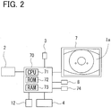
ophthalmic apparatus 1 of the present example may also include for example ahousing 6, adisplay unit 7, anoperation unit 8, theface support unit 9, and others. For instance, thehousing 6 houses theoptometry unit 2, theface photographing unit 3, thedrive unit 4, and others. Thedisplay unit 7 displays for example an observation image of the examinee's eye E, a measured result, and others. For instance, thedisplay unit 7 may be provided integrally with theapparatus 1 or separately from theapparatus 1. Theophthalmic apparatus 1 may also be provided with theoperation unit 8. Thisoperation unit 8 is used for operations to input various settings of theapparatus 1 and start measurement. Theoperation unit 8 is operated by an examiner to enter various operational commands. Theoperation unit 8 may be for example various types of human interfaces, such as a touch panel, a joystick, a mouse, a keyboard, a track ball, and a button. Theface support unit 9 may be provided for example with aforehead rest 10 and achin rest 11. Thechin rest 11 may be moved in up and down directions by driving of a chin-rest drive unit 12. - As shown in
FIG. 2 , thepresent apparatus 1 includes thecontrol unit 70. Thiscontrol unit 70 takes charges of various controls of thepresent apparatus 1. Thecontrol unit 70 includes for example a general CPU (Central Processing Unit) 71, a flash ROM 72, aRAM 73, and others. For instance, the flash ROM 72 has stored an ophthalmic apparatus control program of controlling theophthalmic apparatus 1, default values, and others. For instance, theRAM 73 temporarily stores various information. Thecontrol unit 70 is connected to theoptometry unit 2, theface photographing unit 3, thedrive unit 4, thedisplay unit 7, theoperation unit 8, the chin-rest drive unit 12, the storage unit (e.g., a non-volatile memory) 74, and others. Thestorage unit 74 is a non-transitory storage medium capable of retaining stored contents even if power supply is shut off. For example, a hard disc drive, a removable USB flash memory, and others may be used as thestorage unit 74. - The
face photographing unit 3 photographs the face of the examinee including at least one of his/her right and left eyes. For instance, as shown inFIG. 3 , theface photographing unit 3 of the present example is provided with a photographingoptical system 3A for photographing the examinee's face. The photographingoptical system 3A mainly includes for example an imaging element 3Aa and an imaging lens 3Ab. Theface photographing unit 3 is for example a non-telecentric optical system. Thus, the apparatus does not need to include any telecentric lens and thus can provide a simple structure. The apparatus can further provide a wider photographing range than the telecentric optical system. - The
face photographing unit 3 of the present example is moved together with theoptometry unit 2 by thedrive unit 4. Of course, for instance, theface photographing unit 3 may be fixed to the base table 5 and held against movement. - In
FIG. 1 , theface photographing unit 3 is placed under theoptometry unit 2. However, the position of theface photographing unit 3 is not limited thereto. For instance, theface photographing unit 3 may be provided above or lateral to theoptometry unit 2. They may also be provided so that a measurement optical axis of theoptometry unit 2 becomes coaxial with a photographing optical axis of theface photographing unit 3. As an alternative, theface photographing unit 3 may be placed independently from movement of theoptometry unit 2. For instance, theface photographing unit 3 may be provided on the base table 5 so as to be three-dimensionally driven, so thatface photographing unit 3 is driven in a three-dimensional manner by another drive unit (a second drive unit), which is different from the drive unit (a first drive unit) 4. Of course, the first drive unit for moving theoptometry unit 2 may serve as the second drive unit for moving the photographingunit 3 as in the present example. - The
optometry unit 2 performs measurement, examination, photographing, and so on, of the examinee's eye E. Theoptometry unit 2 may be provided with for example a measurement optical system for measuring refractive power of the examinee's eye E. As shown inFIG. 3 , for instance, theoptometry unit 2 may include a measurementoptical system 20, a fixation target presentingoptical system 40, an alignment target projectingoptical system 50, and an anterior segment photographingoptical system 60. - The measurement
optical system 20 includes a projecting optical system (a light projecting optical system) 20a and a light receivingoptical system 20b. The projectingoptical system 20a projects a light flux to a fundus Ef through a pupil of the examinee's eye E. The light receivingoptical system 20b extracts a reflection light flux (fundus reflection light) as ring-shaped light reflected from the fundus Ef through a pupil and its surrounding area and images a ring-shaped fundus reflection image to be mainly used for measurement of refractive power. - The projecting
optical system 20a includes, on its optical axis L1, ameasurement light source 21, arelay lens 22, ahole mirror 23, and anobjective lens 24. Thelight source 21 projects a spot-shaped source image on the fundus Ef through therelay lens 22 to theobjective lens 24 and a pupil central area. Thelight source 21 is moved along the optical axis L1 by amovement mechanism 33. Thehole mirror 23 is provided with an aperture allowing a light flus emitted from thelight source 21 via therelay lens 22 to pass through. Thehole mirror 23 is placed in an optically conjugate position with the pupil of the examinee's eye E. - The light receiving
optical system 20b shares thehole mirror 23 and theobjective lens 24 with the projectingoptical system 20a. The light receivingoptical system 20b further includes arelay lens 26 and atotal reflection mirror 27. Moreover, the light receivingoptical system 20b includes a light-receivingdiaphragm 28, acollimator lens 29, aring lens 30, and animaging element 32, on an optical axis L2 corresponding to a reflection direction of thehole mirror 23. As theimaging element 32, a two-dimensional light-receiving element, such as an area CCD, can be used. The light-receivingdiaphragm 28, thecollimator lens 29, thering lens 30, and theimaging element 32 are moved integrally with themeasurement light source 21 of the projectingoptical system 20a in the optical axis L2 direction by themovement mechanism 33. When thelight source 21 is placed in an optically conjugate position with the fundus Ef by themovement mechanism 33, the light-receivingdiaphragm 28 and theimaging element 32 are also placed in each optically conjugate position with the fundus Ef. - The
ring lens 30 is an optical element to form the fundus reflection light directed from theobjective lens 24 via thecollimator lens 29 into a ring shape. Thering lens 30 has a ring-shaped lens part and a light-shielding part. Further, when the light-receivingdiaphragm 28 and theimaging element 32 are placed in each optically conjugate position with the fundus Ef, thering lens 30 is disposed in an optically conjugate position with a pupil of the examinee's eye E. Theimaging element 32 receives the ring-shaped fundus reflection light (hereinafter, called a ring image) passing through thering lens 30. Theimaging element 32 outputs image information on the received ring image to theCPU 71. Consequently, theCPU 71 displays the ring image on thedisplay unit 7 and calculates the refractive power based on the ring image, and so on. - In the present example, furthermore, as shown in
FIG. 3 , adichroic mirror 39 is placed between theobjective lens 24 and the examinee's eye E. Thedichroic mirror 39 transmits the light emitted from thelight source 21 and the fundus reflection light deriving from the light from thelight source 21. Thedichroic mirror 39 directs a light flux from a fixation target presentingoptical system 40 described later to the examinee's eye E. Further, thedichroic mirror 39 reflects the light reflected from an anterior segment, deriving from an alignment target projectingoptical system 50 described later, to direct this anterior segment reflection light to the anterior segment photographingoptical system 60. - As shown in
FIG. 3 , in front of the examinee's eye E, the alignment target projectingoptical system 50 is placed. This alignment target projectingoptical system 50 mainly projects a target image to be used for positioning (alignment) of the optical system with respect to the examinee's eye E onto the anterior segment. The alignment target projectingoptical system 50 includes a ring target projectingoptical system 51 and a target projectingoptical system 52. The ring target projectingoptical system 51 projects diffusion light onto a cornea of the examinee's eye E to project thereon a ring target. In theophthalmic apparatus 1 of the present example, the ring target projectingoptical system 51 is also used for anterior segment illumination to illuminate the anterior segment of the examinee's eye E. The target projectingoptical system 52 projects parallel light onto a cornea of the examinee's eye E to project thereon an infinite target. - The fixation target presenting
optical system 40 includes alight source 41, afixation target 42, and arelay lens 43 on an optical axis L4 corresponding to a reflection direction of thereflection mirror 46. Thefixation target 42 is used to make the examinee's eye E fixate thereat during objective refractive power measurement. For instance, when illuminated with light of thelight source 41, thefixation target 42 is presented to the examinee's eye E. - The
light source 41 and thefixation target 42 are integrally moved by adrive mechanism 48 in a direction of the optical axis L4. A presenting position (a presenting distance) of the fixation target may be changed by movement of thelight source 41 and thefixation target 42. This enables performing refractive power measurement with fogging applied to the examinee's eye E. - The anterior segment photographing
optical system 60 includes animaging lens 61 and animaging element 62 on an optical axis L3 corresponding to a reflection direction of ahalf mirror 63. Theimaging element 62 is placed in an optically conjugate position with the anterior segment of the examinee's eye E. Theimaging element 62 captures an image of the anterior segment illuminated by the ring target projectingoptical system 51. Output from theimaging element 62 is input to theCPU 71. As a result, an anterior segment image Ia of the examinee's eye E imaged by theimaging element 62 is displayed on the display unit (seeFIG. 2 ). Theimaging element 62 captures an alignment target image (a ring target and an infinite target in the present example) formed on a cornea of the examinee's eye E by the alignment target projectingoptical system 50. Accordingly, theCPU 71 can detect an alignment target image based on an imaging result of theimaging element 62. TheCPU 71 also can determine whether an alignment state is appropriate or not based on the position at which the alignment target image is detected. - Control operation of the
present apparatus 1 is explained below. Thepresent apparatus 1 for example automatically performs positioning (alignment) between theoptometry unit 2 and the examinee's eye E for examination of the examinee's eye E. In the present example, for instance, detection of a bright spot (a luminescent spot) by the anterior segment photographingoptical system 60 and detection of an eye by theface photographing unit 3 are performed in parallel. When theCPU 71 detects the bright spot (alignment target) from an anterior segment image Ia (seeFIG. 2 ), theCPU 71 can calculate an alignment position from that detected position. When the pupil can be detected from the face image Pi, the direction in which the examinee's eye E is located ("direction of the examinee's eye E") when seen from theface photographing unit 3 in a real space is found based on a coordinate of the examinee's eye of the face image Pi and the information on the photographing unit 3 (e.g., positional information, camera parameter, and others). The present example utilizes those two types of data. Until the bright spot is detected by the anterior segment photographingoptical system 60, theoptometry unit 2 is moved based on the direction E1 of the examinee's eye E, which has been found from the face image Pi. After the bright spot has been detected by the anterior segment photographingoptical system 60, for example, theCPU 71 performs alignment with the bright spot and then, upon completion of the alignment, carries out the measurement. The control flow is explained referring to a flowchart ofFIG. 4 . - The
CPU 71 firstly determines whether or not a target (e.g., a bright spot) projected onto the anterior segment of the examinee's eye E by the target projectingoptical system 50 is detected. For instance, theCPU 71 detects the bright spot by processing the image photographed by the anterior segment photographingoptical system 60. For instance, theCPU 71 obtains information on the bright spot in the image Ia photographed by the anterior segment photographingoptical system 60. - Successively, the
CPU 71 determines for instance whether or not the bright spot is present in the anterior segment image Ia based on a detection result in step S1. When the bright spot is present, for instance, theCPU 71 advances the processing to step S7. In the absence of the bright spot, theCPU 71 goes to the processing in step S3. For instance, theCPU 71 can determine that the bright spot is detected when the luminance equal to or higher than a threshold is detected, while determine that the bright spot is not detected when the luminance equal to or higher than a threshold is not detected. - When the bright spot is not detected in step S2, the
CPU 71 obtains an image of the face including the examinee's eye E photographed by theface photographing unit 3. TheCPU 71 analyzes the obtained face image Pi (seeFIG. 5 ) and detects the examinee's eye E (e.g., pupil). For example, theCPU 71 may be configured to detect an edge of the face image and detect the pupil of the examinee's eye E based on the shape of the edge and others. - When the pupil is detected in step S3, the
CPU 71 goes to the processing in step S5. When the pupil is not detected, theCPU 71 returns to the processing in step S1. - When the pupil is detected in step S4, the
CPU 71 calculates the direction E1 of the examinee's eye E seen from the face photographing unit 3 (seeFIG. 5 ). The direction E1 of the examinee's eye E may be for example a three-dimensional direction (e.g., space vector). TheCPU 71 firstly calculates a coordinate P (xe, ye) of the examinee's eye E (e.g., pupil) on the face image Pi. For instance, the coordinate of the examinee's eye E may be calculated by analysis of the luminance of the face image Pi, the edge, and others. - Herein, the three-dimensional coordinate of the examinee's eye E seen from the
face photographing unit 3 is assumed to be E = (Xe, Ye, Ze), wherein the origin is theface photographing unit 3. At that time, the direction E1 of the examinee's eye E seen from theface photographing unit 3 is E1's unit vector (E1/|E1|). TheCPU 7 determines this direction E1 of the examinee's eye E, for example. - When the examinee's eye is projected at the coordinate P(xe, ye) on the face image Pi, a relationship between E1 and (xe, ye) is given by the following expression (1):

face photographing unit 3, fx and fy are focal distances, s is skew distortion, and (cx, cy) is an optical center on the image. These values are obtained in advance by calibration of theface photographing unit 3. - The expression (1) is expanded and substituted to establish the following simultaneous equations (2).

- The simultaneous equations (2) are solved to find Xe/Ze and Ye,/Ze, so that a ratio Xe:Ye:Ze is found. That is, the direction E1 of the examinee's eye E seen from the
face photographing unit 3 is obtained. In this manner, theCPU 71 may also be configured to determine the direction E1 of the examinee's eye E seen from theface photographing unit 3. - The
CPU 71 sets a drive range of thedrive unit 4 based on the direction E1 of the detected examinee's eye E and moves theoptometry unit 2 within the set drive range. For instance, theCPU 71 shifts the alignment allowable region Aa by the anterior segment photographingoptical system 60 onto the straight line K connecting theface photographing unit 3 and the examinee's eye. Herein, the alignment allowable region Aa is for example a region enabling detection of a three-dimensional position of the examinee's eye E from the. anterior segment image Ia photographed in a certain position by the anterior segment photographingoptical system 60. A positional relationship between an origin O of theface photographing unit 3 and the alignment allowable region Aa by the anterior segment photographingoptical system 60 is known because of the design of the apparatus. Thus, theCPU 71 can cause thedrive unit 4 to move the alignment allowable region Aa onto the straight line K. For instance, theCPU 71 moves the anterior segment photographingoptical system 60 from a position Q1 to a position Q2 so that the straight line K is included in the alignment allowable region Aa as shown inFIG. 6 . Herein, the position Q2 is a location causing a position G1, on the straight like K, closest to the origin O within a measurable range Ea allowing measurement using theoptometry unit 2, to coincide with the gravity point of the alignment allowable region Aa. The measurable range Ea is determined for example based on a working distance of theoptometry unit 2 and the drive range of thedrive unit 4. - The
CPU 71 for instance moves the anterior segment photographingoptical system 60 to the position Q2 and dispose the alignment allowable region Aa on the straight line K. TheCPU 71 further moves the anterior segment photographingoptical system 60 in a direction based on the straight line K while determining whether the bright spot is detected or not on the anterior segment image Ia. For instance, the anterior segment photographingoptical system 60 may be moved from the position Q2 toward a position Q3 as shown inFIG. 7 . Herein, the position Q3 is for example a location causing the position G2 farthest from the origin O of the measurable range Ea to coincide with the gravity point of the alignment allowable region Aa. - The
CPU 71 for instance moves the anterior segment photographingoptical system 60 in the direction E1 along the straight line K so that the alignment allowable region Aa includes at least part of the straight line K. This enables positioning the examinee's eye E in the alignment allowable region Aa during movement from the position Q2 to the position Q3. When the examinee's eye E enters the alignment allowable region Aa, theCPU 71 can perform alignment of theoptometry unit 2 with the examinee's eye E based on the anterior segment image Ia photographed by the anterior segment photographingoptical system 60. - When the
optometry unit 2 is to be moved, this movement may be started from a position at which a relative distance (Z) between theoptometry unit 2 and theface support unit 9 is sufficiently large. This can prevent theoptometry unit 2 from colliding against an examinee. - When the anterior segment photographing
optical system 60 is to be moved from the position Q1 to the position Q2, for instance, it may be moved so that the alignment allowable region Aa and the straight line K overlap in the shortest time, it may be moved at a short total movement distance, or it may be moved in an arbitrary movement direction. For instance, theCPU 71 may be configured to move the alignment allowable region Aa in a direction perpendicular to the straight line K so that the alignment allowable region Aa is moved by a shortest distance to the straight line K. - During movement from the position Q2, this movement has only to be performed so that the alignment allowable region Aa includes a region on the straight line K. That movement direction is not limited to the direction E1 along the straight line K. For instance, when the alignment allowable region Aa is sufficiently wide in the Z direction with respect to the measurable range Ea, the anterior segment photographing
optical system 60 can be moved in an X-Y direction M1 from the position Q2 to the position Q3. Herein, the position Q3 is for example a position at which the position G2 distant from the origin O within the measurable range Ea is included in the alignment allowable region Aa, and a Z-coordinate of the position Q3 is equal to that of Q2. - The
CPU 71 may be configured to update this direction E1 of the examinee's eye E as needed. In the process of alignment, the visual line of the examinee's eye E may change in some cases. In a case where a fixation target is not visible to an examinee, for example, his/her visual line is not fixed. A coordinate (xe, ye) of a pupil on the anterior segment image Ia changes depending on the direction of the visual line of the examinee's eye E. As a result, the direction E1 of the examinee's eye E also changes. Accordingly, the examinee's eye E in a measurable state (a fixated state) may not be present in the direction E1 of the examinee's eye E determined at the start of measurement. Therefore theCPU 71 may be configured to update the direction E1 of the examinee's eye E in association with time change and movement of the apparatus. - The
CPU 71 controls thedrive unit 4 based on the position of the bright spot detected in step S1 to adjust the measurement axis L1 of theoptometry unit 2 to the examinee's eye E. - Upon completion of driving for alignment, the
CPU 71 determines whether the alignment has been completed or not. For instance, this determination is made, referring to the image produced by the anterior segment photographingoptical system 60, on whether a corneal reflection image falls within the alignment allowable range. - When the
CPU 71 determines in step S8 that the alignment has been completed, theCPU 71 causes theoptometry unit 2 to start measurement of the examinee's eye E. For instance, theoptometry unit 2 measures eye refractive power of the examinee's eye E. Needless to say, not limited to measurement of the refractive power, various measurement, photographing, and so on are executed according to the types of optometry units. - In the
ophthalmic apparatus 1 of the present example configured as above, theoptometry unit 2 is moved to the alignment allowable region Aa based on the direction E1 of the examinee's eye E obtained from the face image Pi photographed by theface photographing unit 3. Accordingly, for instance, theoptometry unit 2 can be automatically moved to a position allowing alignment with respect to the examinee's eye E even without using a telecentric optical system, a stereo camera, and others as the photographingoptical system 3A of theface photographing unit 3. - In a configuration described in the present example that the
face photographing unit 3 is provided separately from a measurement system (e.g., theoptometry unit 2 and others) as in the present example, theoptometry unit 2 can be automatically moved to an alignment allowing position in an independent manner from the measurement system. Thus, this configuration is easily applicable to various types of ophthalmic apparatuses. - In the aforementioned examples, the direction E1 of the examinee's eye E seen from the
face photographing unit 3 is obtained. However, the present disclosure is not limited thereto. For instance, theCPU 71 may also be configured to calculate a direction of the corner of the eye seen from theface photographing unit 3. For instance, three-dimensional relative positions of the corner and the pupil of the eye are determined in advance and information on those positions is stored in the apparatus. In this case, theCPU 71 detects the eye's corner on the face image Pi and calculates the direction of the eye's corner in the same manner as above. TheCPU 71 obtains the direction E1 of the examinee's eye E seen from theface photographing unit 3 based on the restrictive condition obtained from the direction of the eye's corner and the three-dimensional relative positions of the eye's corner and the pupil. By utilizing this, theCPU 71 may perform the aforementioned alignment. The position change of the corner of the eye is less caused by visual line change, so that theoptometry unit 2 can be moved in a stable direction even when the visual line changes. - The
CPU 1 may be configured to obtain the face image Pi including both, right and left, eyes of the examinee photographed by theface photographing unit 3. In this case, theCPU 71 may be configured to calculate both directions of those right and left eyes seen from theface photographing unit 3 and store the calculated directions in thestorage unit 74 and others. When measurement on one of the examinee's eyes has been completed and alignment to the other eye is to be performed, the right eye and the left eye may also be changed over based on the position of the eye having been subjected to measurement and the direction of the other eye seen from theface photographing unit 3. For instance, theCPU 71 may be configured to move theoptometry unit 2 from the position where one of the examinee's eyes has been measured toward the straight line on which the other examinee's eye is present. This enables smooth change-over of the right eye and the left eye. - A method for detecting the examinee's eye E from an image may include various image processing methods by for example detecting a pupil by infrared photographing, detecting an edge of a luminance value, and other techniques. In the case of photographing the face of an examinee with infrared light, his/her skin shows up white and the pupil shows up black. Thus, the
CPU 71 may be configured to detect, as a pupil, a circular black (low luminance) portion from an infrared image obtained by the infrared photography. With the aforementioned method, theCPU 71 detects the examinee's eye E from the face image Pi and acquires the information on the two-dimensional position. - In the present example, the alignment target is detected on the anterior segment image Ia photographed by the anterior segment photographing
optical system 60 to perform final alignment. However, the present disclosure is not limited thereto. For instance, theCPU 71 may be configured to perform final alignment from a pupil position on the anterior segment image Ia, contrast, edge, and others.
Claims (11)
- An ophthalmic apparatus (1) for examining an eye (E) of an examinee, comprising:optometry means (2) configured to examine the examinee's eye;drive means (4) for relatively moving the optometry means three-dimensionally with respect to the examinee's eye;first photographing means (3) configured to photograph a face of the examinee including at least one of right and left eyes of the examinee; andcontrol means (70) configured to control the drive means,characterized in that
the control means is further configured to restrict a drive range of the drive means based on a two-dimensional position (P(xe, ye)) of the examinee's eye on a first image (Pi) photographed by the first photographing means, the two-dimensional position being specified by image processing on the first image, and information on the first photographing means. - The ophthalmic apparatus of claim 1, wherein the control means (70) is further configured to restrict the drive range of the drive means based on a three-dimensional relative direction between the examinee's eye (E) and the first photographing means, the three-dimensional relative direction being calculated based on the two-dimensional position and the information on the first photographing means.
- The ophthalmic apparatus of claim 1 or 2, wherein
the optometry means (2) is further provided with second photographing means (60) configured to observe an anterior segment of the examinee's eye (E),
the control means (70) is further configured such that:when a positional relationship between the examinee's eye and the optometry means is obtained by image processing on a second image (Ia) photographed by the second photographing means, the control means (70) controls the drive means (4) based on the positional relationship to perform alignment of the optometry means (2) with respect to the examinee's eye, orwhen the positional relationship is not obtained from the second image, the control means (70) restricts the drive range of the drive means based on the two-dimensional position of the examinee's eye on the first image specified by image processing on the first image (Pi) and the information on the first photographing means. - The ophthalmic apparatus of claim 3, wherein
the control means (70) is configured to calculate a straight line (K) passing through a position of the first photographing means (3) and having a directional vector defined by the three-dimensional relative direction, and restrict the drive range so that at least part of the straight line is included in an alignment allowable region (Aa) by the second photographing means (60). - The ophthalmic apparatus of claim 4, wherein the control means (70) is configured to control the drive means to move the alignment allowable region by the second photographing means (60) along the straight line.
- The ophthalmic apparatus of one of claims 1 to 5, wherein the control means (70) is configured to update a restrictive condition of the drive range based on a new first image (Pi) photographed by the first photographing means (3).
- The ophthalmic apparatus of one of claims 2 to 6, wherein the first photographing means (3) is provided in the optometry means (2) and is moved together with the second photographing means (60) by the drive means (4).
- The ophthalmic apparatus of one of claims 1 to 6 further comprising face support means (9) for supporting the face of the examinee,
wherein a relative positional relationship between the face support means and the first photographing means (3) is constant. - The ophthalmic apparatus of one of claims 1 to 8, wherein the control means (70) is further configured to detect a pupil of the examinee's eye (E) from the first image (Pi) photographed by the first photographing means (3) and restrict the drive range of the drive means based on a two-dimensional position of the pupil on the first image and the information on the first photographing means.
- The ophthalmic apparatus of one of claims 2 to 9 further comprising a target light source (50) for projecting an alignment target onto a cornea of the examinee's eye,
wherein the control means (70) is configured to detect a position of the alignment target from the second image (Ia) photographed by the second photographing means (60) and perform alignment of the optometry means (2) with respect to the examinee's eye based on the position of the alignment target. - A control program for an ophthalmic apparatus (1) for examining an eye (E) of an examinee, the program being executed in the ophthalmic apparatus,
wherein the program is executed by a processor (70) of the ophthalmic apparatus to cause the ophthalmic apparatus to perform:a photographing step of causing photographing means (3) to photograph a face of the examinee, including at least one of right and left eyes of the examinee;a drive step of relatively moving the optometry means three-dimensionally with respect to the examinee's eye based on a two-dimensional position of the examinee's eye on a first image (Pi) photographed in the photographing step, the two-dimensional position being specified by image processing on the first image, and information on the photographing means; andan optometry step of examining the examinee's eye.
Applications Claiming Priority (1)
| Application Number | Priority Date | Filing Date | Title |
|---|---|---|---|
| JP2015193531A JP6634765B2 (en) | 2015-09-30 | 2015-09-30 | Ophthalmic apparatus and ophthalmic apparatus control program |
Publications (2)
| Publication Number | Publication Date |
|---|---|
| EP3150111A1 true EP3150111A1 (en) | 2017-04-05 |
| EP3150111B1 EP3150111B1 (en) | 2020-04-08 |
Family
ID=57288116
Family Applications (1)
| Application Number | Title | Priority Date | Filing Date |
|---|---|---|---|
| EP16191362.9A Active EP3150111B1 (en) | 2015-09-30 | 2016-09-29 | Ophthalmic apparatus and control program for the ophthalmic apparatus |
Country Status (2)
| Country | Link |
|---|---|
| EP (1) | EP3150111B1 (en) |
| JP (1) | JP6634765B2 (en) |
Cited By (3)
| Publication number | Priority date | Publication date | Assignee | Title |
|---|---|---|---|---|
| US11191431B2 (en) | 2017-11-01 | 2021-12-07 | Nidek Co., Ltd. | Ophthalmic apparatus |
| EP3520678B1 (en) * | 2018-02-02 | 2025-04-09 | Nidek Co., Ltd. | Subjective optometry apparatus |
| EP4623804A1 (en) * | 2024-03-27 | 2025-10-01 | Topcon Corporation | Ophthalmologic apparatus |
Families Citing this family (2)
| Publication number | Priority date | Publication date | Assignee | Title |
|---|---|---|---|---|
| JP7439688B2 (en) * | 2020-08-05 | 2024-02-28 | 株式会社ニデック | Ophthalmology equipment and ophthalmology equipment control program |
| JP7718139B2 (en) * | 2021-07-27 | 2025-08-05 | 株式会社ニデック | ophthalmology equipment |
Citations (6)
| Publication number | Priority date | Publication date | Assignee | Title |
|---|---|---|---|---|
| JPH10216089A (en) | 1997-02-10 | 1998-08-18 | Nidek Co Ltd | Opthalmonogy device |
| US20010024264A1 (en) * | 2000-02-24 | 2001-09-27 | Yoshimi Kohayakawa | Ophthalmologic apparatus |
| EP2085023A1 (en) * | 2008-02-01 | 2009-08-05 | Nidek Co., Ltd. | Ophtalmic apparatus |
| EP2505127A2 (en) * | 2011-03-31 | 2012-10-03 | Canon Kabushiki Kaisha | Control apparatus, imaging control method, and storage medium |
| JP2013027537A (en) * | 2011-07-28 | 2013-02-07 | Nidek Co Ltd | Ophthalmic photographing device |
| JP2013066760A (en) | 2012-12-13 | 2013-04-18 | Nidek Co Ltd | Ophthalmic apparatus |
Family Cites Families (5)
| Publication number | Priority date | Publication date | Assignee | Title |
|---|---|---|---|---|
| JPH1040386A (en) * | 1996-07-25 | 1998-02-13 | Oki Electric Ind Co Ltd | Iris recognition system |
| JP3935834B2 (en) * | 2002-11-29 | 2007-06-27 | 株式会社ニデック | Ophthalmic equipment |
| FR2980681A3 (en) * | 2011-09-29 | 2013-04-05 | Fittingbox | METHOD OF DETERMINING OCULAR AND OPTICAL MEASUREMENTS OF INTEREST FOR THE MANUFACTURE AND MOUNTING OF GLASSES OF CORRECTIVE GLASSES USING A CAMERA IN A NON-CONTROLLED CONTEXT |
| TWI494868B (en) * | 2013-04-30 | 2015-08-01 | Optical apparatus and operating method thereof | |
| JP6268303B2 (en) * | 2014-02-04 | 2018-01-24 | フラウンホーファー−ゲゼルシャフト・ツール・フェルデルング・デル・アンゲヴァンテン・フォルシュング・アインゲトラーゲネル・フェライン | 2D image analyzer |
-
2015
- 2015-09-30 JP JP2015193531A patent/JP6634765B2/en active Active
-
2016
- 2016-09-29 EP EP16191362.9A patent/EP3150111B1/en active Active
Patent Citations (6)
| Publication number | Priority date | Publication date | Assignee | Title |
|---|---|---|---|---|
| JPH10216089A (en) | 1997-02-10 | 1998-08-18 | Nidek Co Ltd | Opthalmonogy device |
| US20010024264A1 (en) * | 2000-02-24 | 2001-09-27 | Yoshimi Kohayakawa | Ophthalmologic apparatus |
| EP2085023A1 (en) * | 2008-02-01 | 2009-08-05 | Nidek Co., Ltd. | Ophtalmic apparatus |
| EP2505127A2 (en) * | 2011-03-31 | 2012-10-03 | Canon Kabushiki Kaisha | Control apparatus, imaging control method, and storage medium |
| JP2013027537A (en) * | 2011-07-28 | 2013-02-07 | Nidek Co Ltd | Ophthalmic photographing device |
| JP2013066760A (en) | 2012-12-13 | 2013-04-18 | Nidek Co Ltd | Ophthalmic apparatus |
Cited By (3)
| Publication number | Priority date | Publication date | Assignee | Title |
|---|---|---|---|---|
| US11191431B2 (en) | 2017-11-01 | 2021-12-07 | Nidek Co., Ltd. | Ophthalmic apparatus |
| EP3520678B1 (en) * | 2018-02-02 | 2025-04-09 | Nidek Co., Ltd. | Subjective optometry apparatus |
| EP4623804A1 (en) * | 2024-03-27 | 2025-10-01 | Topcon Corporation | Ophthalmologic apparatus |
Also Published As
| Publication number | Publication date |
|---|---|
| JP6634765B2 (en) | 2020-01-22 |
| EP3150111B1 (en) | 2020-04-08 |
| JP2017064058A (en) | 2017-04-06 |
Similar Documents
| Publication | Publication Date | Title |
|---|---|---|
| US11191431B2 (en) | Ophthalmic apparatus | |
| JP6238551B2 (en) | Ophthalmic apparatus, control method for ophthalmic apparatus, and program | |
| US9888846B2 (en) | Ophthalmological apparatus | |
| CN109310316B (en) | Ophthalmic device | |
| JP6071304B2 (en) | Ophthalmic apparatus and alignment method | |
| JP6641730B2 (en) | Ophthalmic apparatus and ophthalmic apparatus program | |
| EP3150111B1 (en) | Ophthalmic apparatus and control program for the ophthalmic apparatus | |
| US20130162946A1 (en) | Ophthalmologic apparatus, and ophthalmologic method and program | |
| JP7104516B2 (en) | Tomographic imaging device | |
| JP7459491B2 (en) | Ophthalmology measuring device | |
| JP7786396B2 (en) | Ophthalmic device and control program for the device | |
| JP7271976B2 (en) | ophthalmic equipment | |
| JP6589378B2 (en) | Ophthalmic measuring device | |
| JP6769092B2 (en) | Ophthalmic equipment | |
| JP7550586B2 (en) | Ophthalmic device and method of operation thereof | |
| JP6843527B2 (en) | Ophthalmic equipment and ophthalmic equipment control program | |
| JP6769091B2 (en) | Ophthalmic equipment and ophthalmic equipment control program | |
| JP7187769B2 (en) | Ophthalmic device and ophthalmic device control program | |
| JP7491218B2 (en) | Ophthalmic device and ophthalmic device control program | |
| JP7434729B2 (en) | Ophthalmic equipment and ophthalmic equipment control program | |
| JP6733292B2 (en) | Ophthalmic device and ophthalmic device control program | |
| JP6927389B2 (en) | Ophthalmic equipment | |
| JP6844949B2 (en) | Ophthalmic equipment | |
| JP7423912B2 (en) | Ophthalmic equipment and ophthalmic equipment control program | |
| WO2023145638A1 (en) | Ophthalmic device and ophthalmic program |
Legal Events
| Date | Code | Title | Description |
|---|---|---|---|
| PUAI | Public reference made under article 153(3) epc to a published international application that has entered the european phase |
Free format text: ORIGINAL CODE: 0009012 |
|
| STAA | Information on the status of an ep patent application or granted ep patent |
Free format text: STATUS: THE APPLICATION HAS BEEN PUBLISHED |
|
| AK | Designated contracting states |
Kind code of ref document: A1 Designated state(s): AL AT BE BG CH CY CZ DE DK EE ES FI FR GB GR HR HU IE IS IT LI LT LU LV MC MK MT NL NO PL PT RO RS SE SI SK SM TR |
|
| AX | Request for extension of the european patent |
Extension state: BA ME |
|
| STAA | Information on the status of an ep patent application or granted ep patent |
Free format text: STATUS: REQUEST FOR EXAMINATION WAS MADE |
|
| 17P | Request for examination filed |
Effective date: 20171005 |
|
| RBV | Designated contracting states (corrected) |
Designated state(s): AL AT BE BG CH CY CZ DE DK EE ES FI FR GB GR HR HU IE IS IT LI LT LU LV MC MK MT NL NO PL PT RO RS SE SI SK SM TR |
|
| GRAP | Despatch of communication of intention to grant a patent |
Free format text: ORIGINAL CODE: EPIDOSNIGR1 |
|
| STAA | Information on the status of an ep patent application or granted ep patent |
Free format text: STATUS: GRANT OF PATENT IS INTENDED |
|
| RIC1 | Information provided on ipc code assigned before grant |
Ipc: A61B 3/15 20060101AFI20191031BHEP |
|
| INTG | Intention to grant announced |
Effective date: 20191128 |
|
| GRAS | Grant fee paid |
Free format text: ORIGINAL CODE: EPIDOSNIGR3 |
|
| GRAA | (expected) grant |
Free format text: ORIGINAL CODE: 0009210 |
|
| STAA | Information on the status of an ep patent application or granted ep patent |
Free format text: STATUS: THE PATENT HAS BEEN GRANTED |
|
| AK | Designated contracting states |
Kind code of ref document: B1 Designated state(s): AL AT BE BG CH CY CZ DE DK EE ES FI FR GB GR HR HU IE IS IT LI LT LU LV MC MK MT NL NO PL PT RO RS SE SI SK SM TR |
|
| REG | Reference to a national code |
Ref country code: CH Ref legal event code: EP Ref country code: AT Ref legal event code: REF Ref document number: 1253233 Country of ref document: AT Kind code of ref document: T Effective date: 20200415 |
|
| REG | Reference to a national code |
Ref country code: DE Ref legal event code: R096 Ref document number: 602016033426 Country of ref document: DE |
|
| REG | Reference to a national code |
Ref country code: IE Ref legal event code: FG4D |
|
| REG | Reference to a national code |
Ref country code: NL Ref legal event code: MP Effective date: 20200408 |
|
| REG | Reference to a national code |
Ref country code: LT Ref legal event code: MG4D |
|
| PG25 | Lapsed in a contracting state [announced via postgrant information from national office to epo] |
Ref country code: NL Free format text: LAPSE BECAUSE OF FAILURE TO SUBMIT A TRANSLATION OF THE DESCRIPTION OR TO PAY THE FEE WITHIN THE PRESCRIBED TIME-LIMIT Effective date: 20200408 Ref country code: LT Free format text: LAPSE BECAUSE OF FAILURE TO SUBMIT A TRANSLATION OF THE DESCRIPTION OR TO PAY THE FEE WITHIN THE PRESCRIBED TIME-LIMIT Effective date: 20200408 Ref country code: NO Free format text: LAPSE BECAUSE OF FAILURE TO SUBMIT A TRANSLATION OF THE DESCRIPTION OR TO PAY THE FEE WITHIN THE PRESCRIBED TIME-LIMIT Effective date: 20200708 Ref country code: PT Free format text: LAPSE BECAUSE OF FAILURE TO SUBMIT A TRANSLATION OF THE DESCRIPTION OR TO PAY THE FEE WITHIN THE PRESCRIBED TIME-LIMIT Effective date: 20200817 Ref country code: GR Free format text: LAPSE BECAUSE OF FAILURE TO SUBMIT A TRANSLATION OF THE DESCRIPTION OR TO PAY THE FEE WITHIN THE PRESCRIBED TIME-LIMIT Effective date: 20200709 Ref country code: SE Free format text: LAPSE BECAUSE OF FAILURE TO SUBMIT A TRANSLATION OF THE DESCRIPTION OR TO PAY THE FEE WITHIN THE PRESCRIBED TIME-LIMIT Effective date: 20200408 Ref country code: IS Free format text: LAPSE BECAUSE OF FAILURE TO SUBMIT A TRANSLATION OF THE DESCRIPTION OR TO PAY THE FEE WITHIN THE PRESCRIBED TIME-LIMIT Effective date: 20200808 Ref country code: FI Free format text: LAPSE BECAUSE OF FAILURE TO SUBMIT A TRANSLATION OF THE DESCRIPTION OR TO PAY THE FEE WITHIN THE PRESCRIBED TIME-LIMIT Effective date: 20200408 |
|
| REG | Reference to a national code |
Ref country code: AT Ref legal event code: MK05 Ref document number: 1253233 Country of ref document: AT Kind code of ref document: T Effective date: 20200408 |
|
| PG25 | Lapsed in a contracting state [announced via postgrant information from national office to epo] |
Ref country code: HR Free format text: LAPSE BECAUSE OF FAILURE TO SUBMIT A TRANSLATION OF THE DESCRIPTION OR TO PAY THE FEE WITHIN THE PRESCRIBED TIME-LIMIT Effective date: 20200408 Ref country code: LV Free format text: LAPSE BECAUSE OF FAILURE TO SUBMIT A TRANSLATION OF THE DESCRIPTION OR TO PAY THE FEE WITHIN THE PRESCRIBED TIME-LIMIT Effective date: 20200408 Ref country code: BG Free format text: LAPSE BECAUSE OF FAILURE TO SUBMIT A TRANSLATION OF THE DESCRIPTION OR TO PAY THE FEE WITHIN THE PRESCRIBED TIME-LIMIT Effective date: 20200708 Ref country code: RS Free format text: LAPSE BECAUSE OF FAILURE TO SUBMIT A TRANSLATION OF THE DESCRIPTION OR TO PAY THE FEE WITHIN THE PRESCRIBED TIME-LIMIT Effective date: 20200408 |
|
| PG25 | Lapsed in a contracting state [announced via postgrant information from national office to epo] |
Ref country code: AL Free format text: LAPSE BECAUSE OF FAILURE TO SUBMIT A TRANSLATION OF THE DESCRIPTION OR TO PAY THE FEE WITHIN THE PRESCRIBED TIME-LIMIT Effective date: 20200408 |
|
| REG | Reference to a national code |
Ref country code: DE Ref legal event code: R097 Ref document number: 602016033426 Country of ref document: DE |
|
| PG25 | Lapsed in a contracting state [announced via postgrant information from national office to epo] |
Ref country code: SM Free format text: LAPSE BECAUSE OF FAILURE TO SUBMIT A TRANSLATION OF THE DESCRIPTION OR TO PAY THE FEE WITHIN THE PRESCRIBED TIME-LIMIT Effective date: 20200408 Ref country code: RO Free format text: LAPSE BECAUSE OF FAILURE TO SUBMIT A TRANSLATION OF THE DESCRIPTION OR TO PAY THE FEE WITHIN THE PRESCRIBED TIME-LIMIT Effective date: 20200408 Ref country code: CZ Free format text: LAPSE BECAUSE OF FAILURE TO SUBMIT A TRANSLATION OF THE DESCRIPTION OR TO PAY THE FEE WITHIN THE PRESCRIBED TIME-LIMIT Effective date: 20200408 Ref country code: ES Free format text: LAPSE BECAUSE OF FAILURE TO SUBMIT A TRANSLATION OF THE DESCRIPTION OR TO PAY THE FEE WITHIN THE PRESCRIBED TIME-LIMIT Effective date: 20200408 Ref country code: IT Free format text: LAPSE BECAUSE OF FAILURE TO SUBMIT A TRANSLATION OF THE DESCRIPTION OR TO PAY THE FEE WITHIN THE PRESCRIBED TIME-LIMIT Effective date: 20200408 Ref country code: AT Free format text: LAPSE BECAUSE OF FAILURE TO SUBMIT A TRANSLATION OF THE DESCRIPTION OR TO PAY THE FEE WITHIN THE PRESCRIBED TIME-LIMIT Effective date: 20200408 Ref country code: EE Free format text: LAPSE BECAUSE OF FAILURE TO SUBMIT A TRANSLATION OF THE DESCRIPTION OR TO PAY THE FEE WITHIN THE PRESCRIBED TIME-LIMIT Effective date: 20200408 Ref country code: DK Free format text: LAPSE BECAUSE OF FAILURE TO SUBMIT A TRANSLATION OF THE DESCRIPTION OR TO PAY THE FEE WITHIN THE PRESCRIBED TIME-LIMIT Effective date: 20200408 |
|
| PLBE | No opposition filed within time limit |
Free format text: ORIGINAL CODE: 0009261 |
|
| STAA | Information on the status of an ep patent application or granted ep patent |
Free format text: STATUS: NO OPPOSITION FILED WITHIN TIME LIMIT |
|
| PG25 | Lapsed in a contracting state [announced via postgrant information from national office to epo] |
Ref country code: SK Free format text: LAPSE BECAUSE OF FAILURE TO SUBMIT A TRANSLATION OF THE DESCRIPTION OR TO PAY THE FEE WITHIN THE PRESCRIBED TIME-LIMIT Effective date: 20200408 Ref country code: PL Free format text: LAPSE BECAUSE OF FAILURE TO SUBMIT A TRANSLATION OF THE DESCRIPTION OR TO PAY THE FEE WITHIN THE PRESCRIBED TIME-LIMIT Effective date: 20200408 |
|
| 26N | No opposition filed |
Effective date: 20210112 |
|
| PG25 | Lapsed in a contracting state [announced via postgrant information from national office to epo] |
Ref country code: MC Free format text: LAPSE BECAUSE OF FAILURE TO SUBMIT A TRANSLATION OF THE DESCRIPTION OR TO PAY THE FEE WITHIN THE PRESCRIBED TIME-LIMIT Effective date: 20200408 |
|
| REG | Reference to a national code |
Ref country code: CH Ref legal event code: PL |
|
| PG25 | Lapsed in a contracting state [announced via postgrant information from national office to epo] |
Ref country code: SI Free format text: LAPSE BECAUSE OF FAILURE TO SUBMIT A TRANSLATION OF THE DESCRIPTION OR TO PAY THE FEE WITHIN THE PRESCRIBED TIME-LIMIT Effective date: 20200408 |
|
| REG | Reference to a national code |
Ref country code: BE Ref legal event code: MM Effective date: 20200930 |
|
| PG25 | Lapsed in a contracting state [announced via postgrant information from national office to epo] |
Ref country code: LU Free format text: LAPSE BECAUSE OF NON-PAYMENT OF DUE FEES Effective date: 20200929 |
|
| PG25 | Lapsed in a contracting state [announced via postgrant information from national office to epo] |
Ref country code: BE Free format text: LAPSE BECAUSE OF NON-PAYMENT OF DUE FEES Effective date: 20200930 Ref country code: CH Free format text: LAPSE BECAUSE OF NON-PAYMENT OF DUE FEES Effective date: 20200930 Ref country code: IE Free format text: LAPSE BECAUSE OF NON-PAYMENT OF DUE FEES Effective date: 20200929 Ref country code: LI Free format text: LAPSE BECAUSE OF NON-PAYMENT OF DUE FEES Effective date: 20200930 |
|
| PG25 | Lapsed in a contracting state [announced via postgrant information from national office to epo] |
Ref country code: TR Free format text: LAPSE BECAUSE OF FAILURE TO SUBMIT A TRANSLATION OF THE DESCRIPTION OR TO PAY THE FEE WITHIN THE PRESCRIBED TIME-LIMIT Effective date: 20200408 Ref country code: MT Free format text: LAPSE BECAUSE OF FAILURE TO SUBMIT A TRANSLATION OF THE DESCRIPTION OR TO PAY THE FEE WITHIN THE PRESCRIBED TIME-LIMIT Effective date: 20200408 Ref country code: CY Free format text: LAPSE BECAUSE OF FAILURE TO SUBMIT A TRANSLATION OF THE DESCRIPTION OR TO PAY THE FEE WITHIN THE PRESCRIBED TIME-LIMIT Effective date: 20200408 |
|
| PG25 | Lapsed in a contracting state [announced via postgrant information from national office to epo] |
Ref country code: MK Free format text: LAPSE BECAUSE OF FAILURE TO SUBMIT A TRANSLATION OF THE DESCRIPTION OR TO PAY THE FEE WITHIN THE PRESCRIBED TIME-LIMIT Effective date: 20200408 |
|
| P01 | Opt-out of the competence of the unified patent court (upc) registered |
Effective date: 20230509 |
|
| PGFP | Annual fee paid to national office [announced via postgrant information from national office to epo] |
Ref country code: DE Payment date: 20250805 Year of fee payment: 10 |
|
| PGFP | Annual fee paid to national office [announced via postgrant information from national office to epo] |
Ref country code: GB Payment date: 20250807 Year of fee payment: 10 |
|
| PGFP | Annual fee paid to national office [announced via postgrant information from national office to epo] |
Ref country code: FR Payment date: 20250808 Year of fee payment: 10 |