EP3150108B1 - Removable oct device - Google Patents
Removable oct device Download PDFInfo
- Publication number
- EP3150108B1 EP3150108B1 EP15799217.3A EP15799217A EP3150108B1 EP 3150108 B1 EP3150108 B1 EP 3150108B1 EP 15799217 A EP15799217 A EP 15799217A EP 3150108 B1 EP3150108 B1 EP 3150108B1
- Authority
- EP
- European Patent Office
- Prior art keywords
- light
- image detector
- beam splitter
- pass filter
- band pass
- Prior art date
- Legal status (The legal status is an assumption and is not a legal conclusion. Google has not performed a legal analysis and makes no representation as to the accuracy of the status listed.)
- Active
Links
Images

Classifications
-
- A—HUMAN NECESSITIES
- A61—MEDICAL OR VETERINARY SCIENCE; HYGIENE
- A61B—DIAGNOSIS; SURGERY; IDENTIFICATION
- A61B1/00—Instruments for performing medical examinations of the interior of cavities or tubes of the body by visual or photographical inspection, e.g. endoscopes; Illuminating arrangements therefor
- A61B1/00163—Optical arrangements
-
- A—HUMAN NECESSITIES
- A61—MEDICAL OR VETERINARY SCIENCE; HYGIENE
- A61B—DIAGNOSIS; SURGERY; IDENTIFICATION
- A61B1/00—Instruments for performing medical examinations of the interior of cavities or tubes of the body by visual or photographical inspection, e.g. endoscopes; Illuminating arrangements therefor
- A61B1/04—Instruments for performing medical examinations of the interior of cavities or tubes of the body by visual or photographical inspection, e.g. endoscopes; Illuminating arrangements therefor combined with photographic or television appliances
- A61B1/05—Instruments for performing medical examinations of the interior of cavities or tubes of the body by visual or photographical inspection, e.g. endoscopes; Illuminating arrangements therefor combined with photographic or television appliances characterised by the image sensor, e.g. camera, being in the distal end portion
-
- A—HUMAN NECESSITIES
- A61—MEDICAL OR VETERINARY SCIENCE; HYGIENE
- A61B—DIAGNOSIS; SURGERY; IDENTIFICATION
- A61B1/00—Instruments for performing medical examinations of the interior of cavities or tubes of the body by visual or photographical inspection, e.g. endoscopes; Illuminating arrangements therefor
- A61B1/12—Instruments for performing medical examinations of the interior of cavities or tubes of the body by visual or photographical inspection, e.g. endoscopes; Illuminating arrangements therefor with cooling or rinsing arrangements
- A61B1/128—Instruments for performing medical examinations of the interior of cavities or tubes of the body by visual or photographical inspection, e.g. endoscopes; Illuminating arrangements therefor with cooling or rinsing arrangements provided with means for regulating temperature
-
- A—HUMAN NECESSITIES
- A61—MEDICAL OR VETERINARY SCIENCE; HYGIENE
- A61B—DIAGNOSIS; SURGERY; IDENTIFICATION
- A61B10/00—Instruments for taking body samples for diagnostic purposes; Other methods or instruments for diagnosis, e.g. for vaccination diagnosis, sex determination or ovulation-period determination; Throat striking implements
-
- A—HUMAN NECESSITIES
- A61—MEDICAL OR VETERINARY SCIENCE; HYGIENE
- A61B—DIAGNOSIS; SURGERY; IDENTIFICATION
- A61B5/00—Measuring for diagnostic purposes; Identification of persons
- A61B5/0059—Measuring for diagnostic purposes; Identification of persons using light, e.g. diagnosis by transillumination, diascopy, fluorescence
- A61B5/0062—Arrangements for scanning
- A61B5/0066—Optical coherence imaging
-
- G—PHYSICS
- G01—MEASURING; TESTING
- G01B—MEASURING LENGTH, THICKNESS OR SIMILAR LINEAR DIMENSIONS; MEASURING ANGLES; MEASURING AREAS; MEASURING IRREGULARITIES OF SURFACES OR CONTOURS
- G01B9/00—Measuring instruments characterised by the use of optical techniques
- G01B9/02—Interferometers
-
- G—PHYSICS
- G01—MEASURING; TESTING
- G01B—MEASURING LENGTH, THICKNESS OR SIMILAR LINEAR DIMENSIONS; MEASURING ANGLES; MEASURING AREAS; MEASURING IRREGULARITIES OF SURFACES OR CONTOURS
- G01B9/00—Measuring instruments characterised by the use of optical techniques
- G01B9/02—Interferometers
- G01B9/0209—Low-coherence interferometers
- G01B9/02091—Tomographic interferometers, e.g. based on optical coherence
-
- G—PHYSICS
- G01—MEASURING; TESTING
- G01N—INVESTIGATING OR ANALYSING MATERIALS BY DETERMINING THEIR CHEMICAL OR PHYSICAL PROPERTIES
- G01N21/00—Investigating or analysing materials by the use of optical means, i.e. using sub-millimetre waves, infrared, visible or ultraviolet light
- G01N21/17—Systems in which incident light is modified in accordance with the properties of the material investigated
-
- G—PHYSICS
- G02—OPTICS
- G02B—OPTICAL ELEMENTS, SYSTEMS OR APPARATUS
- G02B21/00—Microscopes
-
- G—PHYSICS
- G02—OPTICS
- G02B—OPTICAL ELEMENTS, SYSTEMS OR APPARATUS
- G02B21/00—Microscopes
- G02B21/36—Microscopes arranged for photographic purposes or projection purposes or digital imaging or video purposes including associated control and data processing arrangements
- G02B21/361—Optical details, e.g. image relay to the camera or image sensor
-
- G—PHYSICS
- G02—OPTICS
- G02B—OPTICAL ELEMENTS, SYSTEMS OR APPARATUS
- G02B21/00—Microscopes
- G02B21/36—Microscopes arranged for photographic purposes or projection purposes or digital imaging or video purposes including associated control and data processing arrangements
- G02B21/362—Mechanical details, e.g. mountings for the camera or image sensor, housings
-
- A—HUMAN NECESSITIES
- A61—MEDICAL OR VETERINARY SCIENCE; HYGIENE
- A61B—DIAGNOSIS; SURGERY; IDENTIFICATION
- A61B2560/00—Constructional details of operational features of apparatus; Accessories for medical measuring apparatus
- A61B2560/04—Constructional details of apparatus
- A61B2560/0443—Modular apparatus
Definitions
- the present invention relates to a removable OCT (Optical Coherence Tomography) device and, more particularly, to an OCT device which can be simply mounted without changing the structure of a microscope or an endoscope to implement an OCT system.
- OCT Optical Coherence Tomography
- An OCT device is a device capable of taking tomography images of a human body using interference of light in the infrared band. At the initial stage of technology development, it was possible to obtain images of several frames per second by changing the optical path mechanically. Furthermore, tomography images of several hundred frames per second can be taken by employing a three-dimensional OCT technique that makes use of a wavelength tunable laser and a high-speed digitizer.
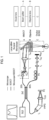
- FIG. 1 shows a conventional OCT device and a microscope equipped with the OCT device.
- the conventional OCT device captures tomography images with an interference signal of the signal light and the reference light by bypassing the light of an object incident on the microscope.
- the OCT device of the type shown in FIG. 1 requires a portion (A) (a beam splitter or the like) of the OCT device to be interposed between the main body of the microscope or the like and the objective lens (B) in order to bypass the signal light.
- A a beam splitter or the like
- B the objective lens
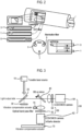
- FIG. 2 shows an endoscope in which an OCT device is integrally formed.
- the endoscope in which the OCT device is integrally formed therewith can simultaneously perform the functions of the endoscope and the OCT device because a transducer and a optical fiber for a light source are formed within the endoscope.
- OCT device of the type shown in FIG. 2 suffers from a problem that all existing conventional endoscopes should be discarded and replaced by new ones, which leads to excessive waste of resources.
- Examples of OCT devices according to the prior art are known from US 2014/098829 , EP 2124718 , KR 101053222 and JP 2008170363 .
- EP2124718 discloses the features of the preamble of claim 1 and is considered to represent the most relevant prior art.
- the present invention is defined in claim 1.
- a removable OCT device is capable of being easily installed and removed and minimizing a change of an existing optical device such as a microscope.
- a removable OCT device includes: a tunable laser configured to emit light to a light output side of an optical device by tuning a wavelength of the light; a first beam splitter installed on a path of the light emitted from the tunable laser; and a reference mirror installed on a path of the light that has passed through the first beam splitter, wherein the removable OCT device is mounted at the light output side of the optical device.
- the removable OCT device adapted to be used in state in which the removable OCT device is mounted on the light output side of an existing optical device. It is therefore possible to remarkably reduce the risk of misalignment or damage of the existing optical device.
- the removable OCT device may be mounted while maintaining the existing optical device. It is therefore possible to use the existing optical device without having to discard the same.
- the removable OCT device may be easily attached and detached. It is therefore possible to use the OCT device by installing the same in one or more optical devices.
- FIG. 3 is a structural diagram of a removable OCT device according to a first example not falling under the scope of claim 1.
- the removable OCT device according to the present embodiment is a device mounted at the light output side of an optical device such as an endoscope, a microscope or the like (at the same side as an ocular lens) and simultaneously acquires a visible light image and an OCT image.
- the removable OCT device includes a tunable laser 10, a first beam splitter 20, a reference mirror 30, a second beam splitter 40, a band pass filter unit 50 and an image detector unit 60.
- the removable OCT device may further include a vibration compensator 70 and an image processor (not shown).
- the tunable laser 10 is a component which emits light to the light output side while tuning the wavelength so that the human body tissue can be taken tomographically by depth, and which makes sure that an infrared ray is reflected from a measurement target object (a human body or the like) to be measured by an optical device (that the light incident on the light output side reaches the measurement target object through the optical device).
- the wavelength is tuned in the infrared region of 750 to 1300 nm. As the wavelength grows longer, the depth of infiltration of the light into the human body tissue becomes deeper.
- the tunable laser 10 may further include an LED, a lamp or the like, which covers a visible ray region, so that the tunable laser 10 can provide a visible ray when the amount of the visible ray emitted from the measurement target object is deficient.
- the first beam splitter 20 is a component which generates a reference light (light for setting a phase reference plane) by allowing a portion of the light emitted from the tunable laser 10 to pass through the first beam splitter 20 and to move toward the reference mirror 30, and generates a signal light (a light reflected or emitted from the measurement target object and containing information of the measurement target object) by reflecting a portion of the light emitted from the tunable laser 10 and allowing the light to move toward the light output side.
- the first beam splitter 20 is configured to reflect the reference light reflected from the reference mirror 30 and is configured to allow the signal light emitted from the light output side to pass through the first beam splitter 20 and to move toward the second beam splitter 40.
- Information on the measurement target object can be obtained by causing the reference light and the signal light, which are generated by the first beam splitter 20 in this way, to interfere with each other.
- the reference mirror 30 is a component which reflects the light passed through the first beam splitter 20 and generates a reference light, namely a light to be compared with phase-shifted signal light.
- the second beam splitter 40 is a component which allows a portion of the light emitted from the light output side and the light emitted from the reference mirror 30 to pass through the second beam splitter 40 while it reflects the other portion to divide the optical path into two. Since the second beam splitter 40 is installed on an optical path of the light emitted from the light output side and passed through the first beam splitter 20, the reference light and the signal light are incident on the second beam splitter 40.
- the removable OCT device according to the present embodiment is configured to simultaneously pass a visible ray of a typical optical device and an infrared ray emitted by the tunable laser 10.
- the removable OCT device includes an infrared ray image detector 62 and a visible light image detector 64 in order to separately take an image of the visible ray and the infrared ray.
- the second beam splitter 40 splits the light to be incident on the infrared image detector 62 and the visible light image detector 64.
- the band pass filter unit 50 is a component which filters the light to be incident on the infrared image detector 62 and the visible light image detector 64.
- the band pass filter unit 50 may include an infrared band pass filter 52 installed on a path of one of the light beams split in the second beam splitter 40 and may further include a visible ray band pass filter 54 installed on a path of the other of the light beams split in the second beam splitter 40.
- the infrared image detector 62 has to receive only an electromagnetic wave of an infrared band as a signal.
- the visible ray band pass filter 54 is an optional component. In general, a CCD or CMOS image detector is sufficient to take visible light images.
- the visible ray band pass filter 54 may be provided when one wishes to enhance the purity of a visible light image by removing the light in the infrared band.
- the image detector unit 60 may include an infrared image detector 62 and a visible light image detector 64.
- the infrared image detector 62 is installed behind the infrared band pass filter 52
- the visible light image detector 64 is installed behind the second beam splitter 40 or the visible ray band pass filter 54.
- the rear side of the second beam splitter 40 refers to a travel path of the light other than the light which is separated by the first beam splitter 20 and is incident on the infrared image detector 62.
- the infrared image detector 62 has to take infrared images in a wavelength range of 750 to 1300 nm. Thus, different types of image detectors are used depending on the wavelength range. Specifically, in the wavelength range of 750 to 1100 nm, a typical CCD or CMOS image detector like the visible light image detector 64 may be used. However, since the typical CCD or CMOS image detector cannot detect an infrared ray of a wavelength of 1100 nm or more, an InGaAs image detector is used.
- the visible light image detector 64 is an image detector used in a typical digital camera. A CCD or CMOS image detector is used as the visible light image detector 64.
- infrared ray image detectors 62 By providing a plurality of infrared ray image detectors 62, it is possible to improve the quality of an OCT image. For example, when images are taken by installing two infrared ray image detectors 62 and synchronizing the image-taking timings thereof, it is possible to obtain two-fold images per unit time and to obtain OCT images having a high quality. When one wishes to obtain images of the same quality, it is possible to shorten the image-taking time by one half. Thus, the images are less susceptible to vibration and are somewhat free from the restrictions in the performance of the vibration compensator 70.
- the visible light image detector 64 may be an ocular lens. Since the human eyes may be regarded as one kind of the visible light image detector 64, it is possible to implement an OCT device capable of taking infrared images with the infrared image detector 62 while seeing visible light images through an ocular lens. In this case, the human eyes serve as the visible ray band pass filter 54. Thus, by removing the visible ray band pass filter 54, it is possible to simplify the configuration of the OCT device.
- the vibration compensator 70 is a component which compensates the vibration of the lens or the image detector unit 60.
- the vibration compensator 70 may be an actuator (of hardware type) which mechanically compensates the vibration of the lens or the image detector unit 60 by measuring the vibration, or may be a processor (of software type) which compensates the vibration through image correction by matching the measured images.
- the vibration compensation is needed for the following reason. Due to the characteristics of the OCT device, a plurality of images is taken within a short period of time while tuning the wavelength (namely, while changing the image-taking depth). At this time, if vibration or position shift occurs, an error may be generated in a stereoscopic image.
- the hardware type vibration compensator 70 is configured to physically cancel the actual vibration.
- the software type vibration compensator 70 is configured to compensate the error, which is generated in the image due to the vibration, through an image processing process.
- the image processor (not shown) is a component which is connected to the image detector unit 60 and configured to process the visible light images and the infrared images acquired in the image detector unit 60.
- Specific forms of the image processor include a field programmable gate array (FPGA), a digital signal processor (DSP), an ARM, and the like.
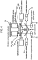
- FIG. 4 is a structural diagram of a removable OCT device according to an embodiment of the present invention.
- the removable OCT device according to the present disclosure is mounted to the light the output side of a binocular optical device.
- the removable OCT device includes a tunable laser 10, a pair of first beam splitters 20, a reference mirror 30, a pair of second beam splitters 40, a pair of band pass filter units 50 and a pair of image detector units 60.
- the removable OCT device may further include a vibration compensator 70 and an image processor. It can be said that the removable OCT device according to this embodiment of the invention is configured to be binocular, namely as a stereo system, by combining, in parallel, two removable OCT devices according to the first embodiment of the present disclosure. Accordingly, the removable OCT device according to the second embodiment of the present disclosure is useful in a device such as a microscope.
- the first beam splitters 20, the second beam splitters 40, the band pass filter units 50 and the image detector units 60 are respectively provided in a pair.
- the tunable laser 10 may be provided in a pair. Since it is desirable to irradiate the same light on an object, it is preferred that there is provided only one tunable laser 10.
- a pair of reference mirrors 30 may be provided and may be respectively installed at the rear side of the first beam splitters 20. Alternatively, one double-sided mirror may be installed as the reference mirror 30.
- a pair of vibration compensators 70 and a pair of image processors may be provided, one in each of the image detector units 60. Alternatively, one vibration compensator 70 and one image processor may be provided in the image detector units 60 as a whole.
- FIG. 5 shows a use state in which the removable OCT device according to the first example not falling under the scope of the invention is mounted to an endoscope.
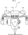
- FIG. 6 shows a use state in which the removable OCT device according to the second embodiment of the present disclosure is mounted to a microscope. It can be noted that the removable OCT device 100 according to the present disclosure can be easily mounted to and removed from an existing optical device such as an endoscope, a microscope or the like.
Landscapes
- Health & Medical Sciences (AREA)
- Life Sciences & Earth Sciences (AREA)
- Physics & Mathematics (AREA)
- Surgery (AREA)
- General Health & Medical Sciences (AREA)
- Engineering & Computer Science (AREA)
- Optics & Photonics (AREA)
- General Physics & Mathematics (AREA)
- Pathology (AREA)
- Veterinary Medicine (AREA)
- Biomedical Technology (AREA)
- Heart & Thoracic Surgery (AREA)
- Medical Informatics (AREA)
- Molecular Biology (AREA)
- Animal Behavior & Ethology (AREA)
- Public Health (AREA)
- Radiology & Medical Imaging (AREA)
- Nuclear Medicine, Radiotherapy & Molecular Imaging (AREA)
- Biophysics (AREA)
- Chemical & Material Sciences (AREA)
- Analytical Chemistry (AREA)
- Multimedia (AREA)
- Biochemistry (AREA)
- Immunology (AREA)
- Investigating Or Analysing Materials By Optical Means (AREA)
- Endoscopes (AREA)
- Microscoopes, Condenser (AREA)
- Instruments For Viewing The Inside Of Hollow Bodies (AREA)
Description
- The present invention relates to a removable OCT (Optical Coherence Tomography) device and, more particularly, to an OCT device which can be simply mounted without changing the structure of a microscope or an endoscope to implement an OCT system.
- An OCT device is a device capable of taking tomography images of a human body using interference of light in the infrared band. At the initial stage of technology development, it was possible to obtain images of several frames per second by changing the optical path mechanically. Nowadays, tomography images of several hundred frames per second can be taken by employing a three-dimensional OCT technique that makes use of a wavelength tunable laser and a high-speed digitizer.
-
FIG. 1 shows a conventional OCT device and a microscope equipped with the OCT device. The conventional OCT device captures tomography images with an interference signal of the signal light and the reference light by bypassing the light of an object incident on the microscope. - However, since the OCT device of the type shown in
FIG. 1 requires a portion (A) (a beam splitter or the like) of the OCT device to be interposed between the main body of the microscope or the like and the objective lens (B) in order to bypass the signal light. This raises a problem that installation of the OCT device is difficult and that the alignment of precision equipment such as a microscope or the like is disturbed. -
FIG. 2 shows an endoscope in which an OCT device is integrally formed. The endoscope in which the OCT device is integrally formed therewith can simultaneously perform the functions of the endoscope and the OCT device because a transducer and a optical fiber for a light source are formed within the endoscope. - However, the OCT device of the type shown in
FIG. 2 suffers from a problem that all existing conventional endoscopes should be discarded and replaced by new ones, which leads to excessive waste of resources. Examples of OCT devices according to the prior art are known fromUS 2014/098829 ,EP 2124718 ,KR 101053222 JP 2008170363 EP2124718 discloses the features of the preamble ofclaim 1 and is considered to represent the most relevant prior art. - The present invention is defined in
claim 1. - Embodiments of the present disclosure solve the problems mentioned above. In some embodiments, a removable OCT device is capable of being easily installed and removed and minimizing a change of an existing optical device such as a microscope.
- A removable OCT device according to one example not falling under the scope of
claim 1 includes: a tunable laser configured to emit light to a light output side of an optical device by tuning a wavelength of the light; a first beam splitter installed on a path of the light emitted from the tunable laser; and a reference mirror installed on a path of the light that has passed through the first beam splitter, wherein the removable OCT device is mounted at the light output side of the optical device. - The removable OCT device adapted to be used in state in which the removable OCT device is mounted on the light output side of an existing optical device. It is therefore possible to remarkably reduce the risk of misalignment or damage of the existing optical device.
- Furthermore, the removable OCT device may be mounted while maintaining the existing optical device. It is therefore possible to use the existing optical device without having to discard the same.
- Moreover, the removable OCT device may be easily attached and detached. It is therefore possible to use the OCT device by installing the same in one or more optical devices.
-
-
FIG. 1 shows a conventional OCT device and a microscope equipped with the OCT device. -
FIG. 2 shows an endoscope with which the OCT device is integrally formed. -
FIG. 3 is a structural diagram of a removable OCT device according to a first embodiment of the present disclosure. -
FIG. 4 is a structural diagram of a removable OCT device according to a second embodiment of the present disclosure. -
FIG. 5 shows a use state in which the removable OCT device according to the first embodiment of the present disclosure is mounted to an endoscope. -
FIG. 6 shows a use state in which the removable OCT device according to the second embodiment of the present disclosure is mounted to a microscope. - A removable OCT device not falling under the scope of
claim 1 will now be described in detail with reference to the accompanying drawings. -
FIG. 3 is a structural diagram of a removable OCT device according to a first example not falling under the scope ofclaim 1. The removable OCT device according to the present embodiment is a device mounted at the light output side of an optical device such as an endoscope, a microscope or the like (at the same side as an ocular lens) and simultaneously acquires a visible light image and an OCT image. The removable OCT device includes atunable laser 10, afirst beam splitter 20, areference mirror 30, asecond beam splitter 40, a bandpass filter unit 50 and animage detector unit 60. The removable OCT device may further include avibration compensator 70 and an image processor (not shown). - The
tunable laser 10 is a component which emits light to the light output side while tuning the wavelength so that the human body tissue can be taken tomographically by depth, and which makes sure that an infrared ray is reflected from a measurement target object (a human body or the like) to be measured by an optical device (that the light incident on the light output side reaches the measurement target object through the optical device). In some embodiments, the wavelength is tuned in the infrared region of 750 to 1300 nm. As the wavelength grows longer, the depth of infiltration of the light into the human body tissue becomes deeper. Thus, by emitting light while changing the wavelength of the light from a short wavelength to a long wavelength, it is possible to acquire stereoscopic interference signals from the surface of the human body tissue to a predetermined depth. An OCT can be implemented by image-processing the interference signals. Thetunable laser 10 may further include an LED, a lamp or the like, which covers a visible ray region, so that thetunable laser 10 can provide a visible ray when the amount of the visible ray emitted from the measurement target object is deficient. - The
first beam splitter 20 is a component which generates a reference light (light for setting a phase reference plane) by allowing a portion of the light emitted from thetunable laser 10 to pass through thefirst beam splitter 20 and to move toward thereference mirror 30, and generates a signal light (a light reflected or emitted from the measurement target object and containing information of the measurement target object) by reflecting a portion of the light emitted from thetunable laser 10 and allowing the light to move toward the light output side. Thefirst beam splitter 20 is configured to reflect the reference light reflected from thereference mirror 30 and is configured to allow the signal light emitted from the light output side to pass through thefirst beam splitter 20 and to move toward thesecond beam splitter 40. Information on the measurement target object can be obtained by causing the reference light and the signal light, which are generated by thefirst beam splitter 20 in this way, to interfere with each other. - The
reference mirror 30 is a component which reflects the light passed through thefirst beam splitter 20 and generates a reference light, namely a light to be compared with phase-shifted signal light. - The
second beam splitter 40 is a component which allows a portion of the light emitted from the light output side and the light emitted from thereference mirror 30 to pass through thesecond beam splitter 40 while it reflects the other portion to divide the optical path into two. Since thesecond beam splitter 40 is installed on an optical path of the light emitted from the light output side and passed through thefirst beam splitter 20, the reference light and the signal light are incident on thesecond beam splitter 40. The removable OCT device according to the present embodiment is configured to simultaneously pass a visible ray of a typical optical device and an infrared ray emitted by thetunable laser 10. Thus, the removable OCT device includes an infraredray image detector 62 and a visiblelight image detector 64 in order to separately take an image of the visible ray and the infrared ray. Thesecond beam splitter 40 splits the light to be incident on theinfrared image detector 62 and the visiblelight image detector 64. - The band
pass filter unit 50 is a component which filters the light to be incident on theinfrared image detector 62 and the visiblelight image detector 64. The bandpass filter unit 50 may include an infraredband pass filter 52 installed on a path of one of the light beams split in thesecond beam splitter 40 and may further include a visible rayband pass filter 54 installed on a path of the other of the light beams split in thesecond beam splitter 40. In the removable OCT device according to the present disclosure, theinfrared image detector 62 has to receive only an electromagnetic wave of an infrared band as a signal. Thus, it is necessary to provide the infraredband pass filter 52 which passes the light of an infrared band. The visible rayband pass filter 54 is an optional component. In general, a CCD or CMOS image detector is sufficient to take visible light images. Thus, the visible rayband pass filter 54 may be provided when one wishes to enhance the purity of a visible light image by removing the light in the infrared band. - The
image detector unit 60 may include aninfrared image detector 62 and a visiblelight image detector 64. On the basis of a travel direction of light, theinfrared image detector 62 is installed behind the infraredband pass filter 52, and the visiblelight image detector 64 is installed behind thesecond beam splitter 40 or the visible rayband pass filter 54. In this regard, the rear side of thesecond beam splitter 40 refers to a travel path of the light other than the light which is separated by thefirst beam splitter 20 and is incident on theinfrared image detector 62. - The
infrared image detector 62 has to take infrared images in a wavelength range of 750 to 1300 nm. Thus, different types of image detectors are used depending on the wavelength range. Specifically, in the wavelength range of 750 to 1100 nm, a typical CCD or CMOS image detector like the visiblelight image detector 64 may be used. However, since the typical CCD or CMOS image detector cannot detect an infrared ray of a wavelength of 1100 nm or more, an InGaAs image detector is used. The visiblelight image detector 64 is an image detector used in a typical digital camera. A CCD or CMOS image detector is used as the visiblelight image detector 64. - By providing a plurality of infrared
ray image detectors 62, it is possible to improve the quality of an OCT image. For example, when images are taken by installing two infraredray image detectors 62 and synchronizing the image-taking timings thereof, it is possible to obtain two-fold images per unit time and to obtain OCT images having a high quality. When one wishes to obtain images of the same quality, it is possible to shorten the image-taking time by one half. Thus, the images are less susceptible to vibration and are somewhat free from the restrictions in the performance of thevibration compensator 70. - The visible
light image detector 64 may be an ocular lens. Since the human eyes may be regarded as one kind of the visiblelight image detector 64, it is possible to implement an OCT device capable of taking infrared images with theinfrared image detector 62 while seeing visible light images through an ocular lens. In this case, the human eyes serve as the visible rayband pass filter 54. Thus, by removing the visible rayband pass filter 54, it is possible to simplify the configuration of the OCT device. - The
vibration compensator 70 is a component which compensates the vibration of the lens or theimage detector unit 60. Thevibration compensator 70 may be an actuator (of hardware type) which mechanically compensates the vibration of the lens or theimage detector unit 60 by measuring the vibration, or may be a processor (of software type) which compensates the vibration through image correction by matching the measured images. In the removable OCT device according to the present disclosure, the vibration compensation is needed for the following reason. Due to the characteristics of the OCT device, a plurality of images is taken within a short period of time while tuning the wavelength (namely, while changing the image-taking depth). At this time, if vibration or position shift occurs, an error may be generated in a stereoscopic image. The hardwaretype vibration compensator 70 is configured to physically cancel the actual vibration. The softwaretype vibration compensator 70 is configured to compensate the error, which is generated in the image due to the vibration, through an image processing process. - The image processor (not shown) is a component which is connected to the
image detector unit 60 and configured to process the visible light images and the infrared images acquired in theimage detector unit 60. Specific forms of the image processor include a field programmable gate array (FPGA), a digital signal processor (DSP), an ARM, and the like. -
FIG. 4 is a structural diagram of a removable OCT device according to an embodiment of the present invention. The removable OCT device according to the present disclosure is mounted to the light the output side of a binocular optical device. The removable OCT device includes atunable laser 10, a pair offirst beam splitters 20, areference mirror 30, a pair ofsecond beam splitters 40, a pair of bandpass filter units 50 and a pair ofimage detector units 60. The removable OCT device may further include avibration compensator 70 and an image processor. It can be said that the removable OCT device according to this embodiment of the invention is configured to be binocular, namely as a stereo system, by combining, in parallel, two removable OCT devices according to the first embodiment of the present disclosure. Accordingly, the removable OCT device according to the second embodiment of the present disclosure is useful in a device such as a microscope. - In order to take images by separating an infrared ray and a visible ray, the
first beam splitters 20, thesecond beam splitters 40, the bandpass filter units 50 and theimage detector units 60 are respectively provided in a pair. Thetunable laser 10 may be provided in a pair. Since it is desirable to irradiate the same light on an object, it is preferred that there is provided only onetunable laser 10. Furthermore, a pair of reference mirrors 30 may be provided and may be respectively installed at the rear side of thefirst beam splitters 20. Alternatively, one double-sided mirror may be installed as thereference mirror 30. A pair ofvibration compensators 70 and a pair of image processors may be provided, one in each of theimage detector units 60. Alternatively, onevibration compensator 70 and one image processor may be provided in theimage detector units 60 as a whole. -
FIG. 5 shows a use state in which the removable OCT device according to the first example not falling under the scope of the invention is mounted to an endoscope.FIG. 6 shows a use state in which the removable OCT device according to the second embodiment of the present disclosure is mounted to a microscope. It can be noted that theremovable OCT device 100 according to the present disclosure can be easily mounted to and removed from an existing optical device such as an endoscope, a microscope or the like.
Claims (14)
- A binocular OCT device (100), comprising:a tunable laser (10) configured to emit light as a tuned wavelength of the light;a first beam splitter (20) installed on a path of the light emitted from the tunable laser; anda reference mirror (30) installed on a path of the light that has passed through the first beam splitter (20),wherein one side of the OCT device (100) is configured to be mounted at a light output side of the optical device where an ocular lens is located so that light reflected by the first beam splitter (20) is irradiated to the ocular lens of the optical device, and the other sides of the OCT device (100) are not configured to be mounted to the optical device characterized in that the binocular OCT device is configured to be attachable to or detachable from a light output side of an optical device for dual eyes and configured by combining, in parallel, two OCT devices.
- The device (100) of Claim 1, wherein the tunable laser (10) includes a laser having a wavelength which falls within a section of 750 to 1300 nm.
- The device (100) of Claim 1, further comprising:
a second beam splitter (40) installed on a path of the light emitted from the light output side and passed through the first beam splitter (20). - The device (100) of Claim 3, further comprising:
a band pass filter unit (50). - The device (100) of Claim 4, wherein the band pass filter (50) unit includes a visible ray band pass filter (54) installed in a first path of the light split by the second beam splitter (40).
- The device (100) of Claim 5, further comprising:
an image detector unit (60) including a visible light image detector (64) disposed at a rear side of the visible ray band pass filter (54). - The device (100) of Claim 6, wherein the visible light image detector (64) is an ocular lens.
- The device (100) of Claim 4, wherein the band pass filter unit (50) includes an infrared band pass filter (52) installed in a second path of the light split by the second beam splitter (40).
- The device (100) of Claim 8, further comprising:
an image detector unit (60) including an infrared ray image detector (62) disposed at a rear side of the infrared band pass filter (52). - The device (100) of Claim 9, wherein the image detector (62) includes a plurality of infrared image detectors.
- The device (100) of Claim 6 or 9, further comprising:
a vibration compensator (70) configured to compensate vibration of the image detector unit (60). - The device (100) of Claim 11, wherein the vibration compensator (70) is an actuator configured to mechanically compensate the vibration of the image detector unit (60) by measuring the vibration.
- The device (100) of Claim 11, wherein the vibration compensator (70) is a processor configured to compensate the vibration by matching and correcting measured images.
- The device (100) of Claim 1, wherein a single double-sided mirror is used in place of the reference mirrors (30) of the two OCT devices (100).
Applications Claiming Priority (2)
| Application Number | Priority Date | Filing Date | Title |
|---|---|---|---|
| KR1020140063402A KR101609365B1 (en) | 2014-05-27 | 2014-05-27 | Removable optical coherence tomography apparatus |
| PCT/KR2015/005324 WO2015182995A1 (en) | 2014-05-27 | 2015-05-27 | Removable oct device |
Publications (4)
| Publication Number | Publication Date |
|---|---|
| EP3150108A1 EP3150108A1 (en) | 2017-04-05 |
| EP3150108A4 EP3150108A4 (en) | 2018-01-24 |
| EP3150108C0 EP3150108C0 (en) | 2025-05-14 |
| EP3150108B1 true EP3150108B1 (en) | 2025-05-14 |
Family
ID=54699261
Family Applications (1)
| Application Number | Title | Priority Date | Filing Date |
|---|---|---|---|
| EP15799217.3A Active EP3150108B1 (en) | 2014-05-27 | 2015-05-27 | Removable oct device |
Country Status (6)
| Country | Link |
|---|---|
| US (1) | US10986996B2 (en) |
| EP (1) | EP3150108B1 (en) |
| JP (1) | JP2017521120A (en) |
| KR (1) | KR101609365B1 (en) |
| CN (1) | CN106413518B (en) |
| WO (1) | WO2015182995A1 (en) |
Families Citing this family (6)
| Publication number | Priority date | Publication date | Assignee | Title |
|---|---|---|---|---|
| JP2017176811A (en) * | 2016-03-28 | 2017-10-05 | ソニー株式会社 | Imaging device, imaging method, and medical observation instrument |
| JPWO2017217498A1 (en) * | 2016-06-16 | 2019-04-11 | 国立大学法人東京農工大学 | Endoscopic expansion device |
| KR102615961B1 (en) * | 2016-09-22 | 2023-12-19 | 엘지전자 주식회사 | Optical coherence tomography device |
| WO2018056726A2 (en) | 2016-09-22 | 2018-03-29 | Lg Electronics Inc. | Optical coherence tomography device |
| WO2018203174A1 (en) | 2017-05-02 | 2018-11-08 | Novartis Ag | Reconfigurable optical coherence tomography (oct) system |
| US11579071B2 (en) | 2019-05-30 | 2023-02-14 | Becton, Dickinson And Company | Phase-correction of radiofrequency-multiplexed signals |
Family Cites Families (38)
| Publication number | Priority date | Publication date | Assignee | Title |
|---|---|---|---|---|
| JPS60140916A (en) | 1983-12-27 | 1985-07-25 | Matsushima Kogyo Co Ltd | Support structure of crystal vibrator |
| JPS60140916U (en) * | 1984-02-29 | 1985-09-18 | オリンパス光学工業株式会社 | Binocular eyepiece adapter for endoscope |
| JPH02140714A (en) * | 1988-11-21 | 1990-05-30 | Olympus Optical Co Ltd | Endoscope system |
| US6485413B1 (en) * | 1991-04-29 | 2002-11-26 | The General Hospital Corporation | Methods and apparatus for forward-directed optical scanning instruments |
| JP3872852B2 (en) * | 1996-02-26 | 2007-01-24 | オリンパス株式会社 | Endoscope TV observation system, light source unit used for endoscope TV observation system, and small light source unit for endoscope |
| US5795295A (en) | 1996-06-25 | 1998-08-18 | Carl Zeiss, Inc. | OCT-assisted surgical microscope with multi-coordinate manipulator |
| JPH10165362A (en) | 1996-12-06 | 1998-06-23 | Yoshiomi Kuriwaka | TV camera device for endoscope |
| CN2303267Y (en) * | 1997-06-09 | 1999-01-06 | 南京理工大学 | Computer contacting type interferometer |
| JP2004073667A (en) * | 2002-08-21 | 2004-03-11 | Pentax Corp | Optical tomography endoscope |
| GB0222970D0 (en) * | 2002-10-04 | 2002-11-13 | Renishaw Plc | Vacuum compatible laser interferometer |
| US7319525B2 (en) | 2003-11-06 | 2008-01-15 | Fortebio, Inc. | Fiber-optic assay apparatus based on phase-shift interferometry |
| US7394547B2 (en) | 2003-11-06 | 2008-07-01 | Fortebio, Inc. | Fiber-optic assay apparatus based on phase-shift interferometry |
| CN101639447B (en) * | 2003-11-06 | 2011-06-29 | 佛特比奥公司 | Optical fiber analysis device based on phase-shift interferometry |
| US7530948B2 (en) * | 2005-02-28 | 2009-05-12 | University Of Washington | Tethered capsule endoscope for Barrett's Esophagus screening |
| US20070121196A1 (en) * | 2005-09-29 | 2007-05-31 | The General Hospital Corporation | Method and apparatus for method for viewing and analyzing of one or more biological samples with progressively increasing resolutions |
| JP4819478B2 (en) * | 2005-10-31 | 2011-11-24 | 株式会社ニデック | Ophthalmic imaging equipment |
| TWI296178B (en) * | 2005-12-12 | 2008-04-21 | Novatek Microelectronics Corp | Image vibration-compensating apparatus and the method thereof |
| JP4939236B2 (en) * | 2007-01-15 | 2012-05-23 | オリンパスメディカルシステムズ株式会社 | SUBJECT INFORMATION ANALYSIS DEVICE, ENDOSCOPE DEVICE, AND SUBJECT INFORMATION ANALYSIS METHOD |
| EP1810610B1 (en) | 2006-01-20 | 2016-09-14 | Olympus Corporation | Method and apparatus for analyzing characteristic information of object with the use of mutual interaction between ultrasound wave and light |
| EP1962079B1 (en) | 2007-02-21 | 2016-06-01 | Agfa HealthCare N.V. | System and method for optical coherence tomography |
| EP2772234B1 (en) * | 2007-03-13 | 2021-05-26 | AMO Development, LLC | Apparatus for creating ocular surgical and relaxing incisions |
| EP2124718B1 (en) * | 2007-03-20 | 2012-10-03 | Topcon Europe Medical B.V. | Apparatus for observing an eye, as well as oct-module |
| US7813609B2 (en) | 2007-11-12 | 2010-10-12 | Lightlab Imaging, Inc. | Imaging catheter with integrated reference reflector |
| JP5306041B2 (en) * | 2008-05-08 | 2013-10-02 | キヤノン株式会社 | Imaging apparatus and method thereof |
| JP5455001B2 (en) | 2008-12-26 | 2014-03-26 | キヤノン株式会社 | Optical tomographic imaging apparatus and control method for optical tomographic imaging apparatus |
| KR101053222B1 (en) | 2009-03-13 | 2011-08-02 | 한국과학기술원 | Optical Coherence Tomography Device Using Multi-line Camera |
| WO2010111795A1 (en) * | 2009-04-03 | 2010-10-07 | Exalos Ag | Light source, and optical coherence tomography module |
| JP5512254B2 (en) | 2009-12-21 | 2014-06-04 | 株式会社トプコン | Optical tomographic imaging apparatus and interference signal processing method thereof |
| US8414564B2 (en) * | 2010-02-18 | 2013-04-09 | Alcon Lensx, Inc. | Optical coherence tomographic system for ophthalmic surgery |
| JP5801577B2 (en) * | 2010-03-25 | 2015-10-28 | キヤノン株式会社 | Optical tomographic imaging apparatus and control method for optical tomographic imaging apparatus |
| JP2012002598A (en) * | 2010-06-15 | 2012-01-05 | Fujifilm Corp | Tomographic image processing device and method and optical interference tomographic image diagnostic device |
| JP5653087B2 (en) * | 2010-06-29 | 2015-01-14 | テルモ株式会社 | Optical tomographic imaging apparatus and operating method thereof |
| DE102010038547B4 (en) | 2010-07-28 | 2012-07-19 | Leica Microsystems (Schweiz) Ag | Image stabilization and recording sensor for an image pickup device of a surgical microscope |
| JP5850292B2 (en) * | 2010-11-05 | 2016-02-03 | 株式会社ニデック | Ophthalmic equipment |
| JP5984693B2 (en) | 2012-01-31 | 2016-09-06 | キヤノン株式会社 | Optical coherence tomography apparatus and optical coherence tomography method |
| US20140309527A1 (en) * | 2013-04-12 | 2014-10-16 | Ninepoint Medical, Inc. | Multiple aperture, multiple modal optical systems and methods |
| JP6527668B2 (en) * | 2014-05-02 | 2019-06-05 | 株式会社トプコン | Ophthalmic surgery apparatus and attachment for ophthalmic surgery |
| DE102016121246A1 (en) * | 2016-11-07 | 2018-05-09 | Carl Zeiss Ag | Method for self-examination of an eye and ophthalmological self-examination device |
-
2014
- 2014-05-27 KR KR1020140063402A patent/KR101609365B1/en active Active
-
2015
- 2015-05-27 JP JP2016569852A patent/JP2017521120A/en active Pending
- 2015-05-27 CN CN201580027857.5A patent/CN106413518B/en active Active
- 2015-05-27 EP EP15799217.3A patent/EP3150108B1/en active Active
- 2015-05-27 US US15/313,701 patent/US10986996B2/en active Active
- 2015-05-27 WO PCT/KR2015/005324 patent/WO2015182995A1/en not_active Ceased
Also Published As
| Publication number | Publication date |
|---|---|
| KR101609365B1 (en) | 2016-04-21 |
| EP3150108A1 (en) | 2017-04-05 |
| US20170188833A1 (en) | 2017-07-06 |
| KR20150136632A (en) | 2015-12-08 |
| US10986996B2 (en) | 2021-04-27 |
| EP3150108C0 (en) | 2025-05-14 |
| CN106413518A (en) | 2017-02-15 |
| WO2015182995A1 (en) | 2015-12-03 |
| JP2017521120A (en) | 2017-08-03 |
| CN106413518B (en) | 2018-11-09 |
| EP3150108A4 (en) | 2018-01-24 |
Similar Documents
| Publication | Publication Date | Title |
|---|---|---|
| US10986996B2 (en) | Removable Optical Coherence Tomography (OCT) device | |
| US20200074608A1 (en) | Time of Flight Camera and Method for Calibrating a Time of Flight Camera | |
| EP2719324A2 (en) | Optical coherence tomography device and optical coherence tomography method using same | |
| US20140320866A1 (en) | Shape Measuring Apparatus | |
| US11054240B2 (en) | Light interference unit and light interference measurement device | |
| JP6345944B2 (en) | Oblique incidence interferometer | |
| JPWO2014038397A1 (en) | Stereoscopic optical system | |
| US11002978B2 (en) | Microscope having a beam splitter assembly | |
| JP4721685B2 (en) | Shape measuring method and shape measuring apparatus | |
| US10620420B2 (en) | Optical system for use with microscope | |
| WO2016002693A1 (en) | Tomography device | |
| CN106093913B (en) | An adjustment method for dual-channel common field of view of laser radar | |
| JP7637614B2 (en) | Measuring device and measuring method | |
| US20140268173A1 (en) | Shape measurement apparatus, measurement method, and method of manufacturing article | |
| US9588260B2 (en) | Microlens substrate and imaging apparatus | |
| KR20170096719A (en) | Image processing device and processing method thereof | |
| EP3282300B1 (en) | Microscope | |
| EP4222449B1 (en) | Method for operating a geodetic instrument, and related geodetic instrument | |
| JP5278890B2 (en) | Light capture and tracking device | |
| JP2013034095A (en) | Imaging apparatus and adapter unit | |
| JP2010249907A (en) | Imaging apparatus and imaging method | |
| JP2022154236A5 (en) | ||
| KR102498742B1 (en) | Multiple focusing-based high-resolution optical coherence tomography apparatus for depth-of-focus enhancement | |
| KR101913959B1 (en) | A image processing device and an optical micorscopy system including the same | |
| JP6608249B2 (en) | Optical pickup device |
Legal Events
| Date | Code | Title | Description |
|---|---|---|---|
| STAA | Information on the status of an ep patent application or granted ep patent |
Free format text: STATUS: THE INTERNATIONAL PUBLICATION HAS BEEN MADE |
|
| PUAI | Public reference made under article 153(3) epc to a published international application that has entered the european phase |
Free format text: ORIGINAL CODE: 0009012 |
|
| STAA | Information on the status of an ep patent application or granted ep patent |
Free format text: STATUS: REQUEST FOR EXAMINATION WAS MADE |
|
| 17P | Request for examination filed |
Effective date: 20161222 |
|
| AK | Designated contracting states |
Kind code of ref document: A1 Designated state(s): AL AT BE BG CH CY CZ DE DK EE ES FI FR GB GR HR HU IE IS IT LI LT LU LV MC MK MT NL NO PL PT RO RS SE SI SK SM TR |
|
| AX | Request for extension of the european patent |
Extension state: BA ME |
|
| DAV | Request for validation of the european patent (deleted) | ||
| DAX | Request for extension of the european patent (deleted) | ||
| A4 | Supplementary search report drawn up and despatched |
Effective date: 20171222 |
|
| RIC1 | Information provided on ipc code assigned before grant |
Ipc: A61B 10/00 20060101ALI20171218BHEP Ipc: G01B 9/02 20060101ALI20171218BHEP Ipc: G02B 21/00 20060101ALI20171218BHEP Ipc: A61B 1/05 20060101AFI20171218BHEP |
|
| STAA | Information on the status of an ep patent application or granted ep patent |
Free format text: STATUS: EXAMINATION IS IN PROGRESS |
|
| 17Q | First examination report despatched |
Effective date: 20210426 |
|
| GRAP | Despatch of communication of intention to grant a patent |
Free format text: ORIGINAL CODE: EPIDOSNIGR1 |
|
| STAA | Information on the status of an ep patent application or granted ep patent |
Free format text: STATUS: GRANT OF PATENT IS INTENDED |
|
| INTG | Intention to grant announced |
Effective date: 20241211 |
|
| GRAS | Grant fee paid |
Free format text: ORIGINAL CODE: EPIDOSNIGR3 |
|
| GRAA | (expected) grant |
Free format text: ORIGINAL CODE: 0009210 |
|
| STAA | Information on the status of an ep patent application or granted ep patent |
Free format text: STATUS: THE PATENT HAS BEEN GRANTED |
|
| AK | Designated contracting states |
Kind code of ref document: B1 Designated state(s): AL AT BE BG CH CY CZ DE DK EE ES FI FR GB GR HR HU IE IS IT LI LT LU LV MC MK MT NL NO PL PT RO RS SE SI SK SM TR |
|
| REG | Reference to a national code |
Ref country code: GB Ref legal event code: FG4D |
|
| REG | Reference to a national code |
Ref country code: CH Ref legal event code: EP |
|
| REG | Reference to a national code |
Ref country code: IE Ref legal event code: FG4D |
|
| REG | Reference to a national code |
Ref country code: DE Ref legal event code: R096 Ref document number: 602015091651 Country of ref document: DE |
|
| U01 | Request for unitary effect filed |
Effective date: 20250515 |
|
| U07 | Unitary effect registered |
Designated state(s): AT BE BG DE DK EE FI FR IT LT LU LV MT NL PT RO SE SI Effective date: 20250528 |
|
| U20 | Renewal fee for the european patent with unitary effect paid |
Year of fee payment: 11 Effective date: 20250528 |
|
| PG25 | Lapsed in a contracting state [announced via postgrant information from national office to epo] |
Ref country code: ES Free format text: LAPSE BECAUSE OF FAILURE TO SUBMIT A TRANSLATION OF THE DESCRIPTION OR TO PAY THE FEE WITHIN THE PRESCRIBED TIME-LIMIT Effective date: 20250514 |
|
| PG25 | Lapsed in a contracting state [announced via postgrant information from national office to epo] |
Ref country code: GR Free format text: LAPSE BECAUSE OF FAILURE TO SUBMIT A TRANSLATION OF THE DESCRIPTION OR TO PAY THE FEE WITHIN THE PRESCRIBED TIME-LIMIT Effective date: 20250815 Ref country code: NO Free format text: LAPSE BECAUSE OF FAILURE TO SUBMIT A TRANSLATION OF THE DESCRIPTION OR TO PAY THE FEE WITHIN THE PRESCRIBED TIME-LIMIT Effective date: 20250814 |
|
| PG25 | Lapsed in a contracting state [announced via postgrant information from national office to epo] |
Ref country code: PL Free format text: LAPSE BECAUSE OF FAILURE TO SUBMIT A TRANSLATION OF THE DESCRIPTION OR TO PAY THE FEE WITHIN THE PRESCRIBED TIME-LIMIT Effective date: 20250514 |
|
| PG25 | Lapsed in a contracting state [announced via postgrant information from national office to epo] |
Ref country code: HR Free format text: LAPSE BECAUSE OF FAILURE TO SUBMIT A TRANSLATION OF THE DESCRIPTION OR TO PAY THE FEE WITHIN THE PRESCRIBED TIME-LIMIT Effective date: 20250514 |
|
| PG25 | Lapsed in a contracting state [announced via postgrant information from national office to epo] |
Ref country code: RS Free format text: LAPSE BECAUSE OF FAILURE TO SUBMIT A TRANSLATION OF THE DESCRIPTION OR TO PAY THE FEE WITHIN THE PRESCRIBED TIME-LIMIT Effective date: 20250814 |
|
| PG25 | Lapsed in a contracting state [announced via postgrant information from national office to epo] |
Ref country code: IS Free format text: LAPSE BECAUSE OF FAILURE TO SUBMIT A TRANSLATION OF THE DESCRIPTION OR TO PAY THE FEE WITHIN THE PRESCRIBED TIME-LIMIT Effective date: 20250914 |
|
| REG | Reference to a national code |
Ref country code: CH Ref legal event code: H13 Free format text: ST27 STATUS EVENT CODE: U-0-0-H10-H13 (AS PROVIDED BY THE NATIONAL OFFICE) Effective date: 20251223 |
|
| PG25 | Lapsed in a contracting state [announced via postgrant information from national office to epo] |
Ref country code: SM Free format text: LAPSE BECAUSE OF FAILURE TO SUBMIT A TRANSLATION OF THE DESCRIPTION OR TO PAY THE FEE WITHIN THE PRESCRIBED TIME-LIMIT Effective date: 20250514 |
|
| PG25 | Lapsed in a contracting state [announced via postgrant information from national office to epo] |
Ref country code: CH Free format text: LAPSE BECAUSE OF NON-PAYMENT OF DUE FEES Effective date: 20250531 |
|
| PG25 | Lapsed in a contracting state [announced via postgrant information from national office to epo] |
Ref country code: CZ Free format text: LAPSE BECAUSE OF FAILURE TO SUBMIT A TRANSLATION OF THE DESCRIPTION OR TO PAY THE FEE WITHIN THE PRESCRIBED TIME-LIMIT Effective date: 20250514 |
|
| PG25 | Lapsed in a contracting state [announced via postgrant information from national office to epo] |
Ref country code: SK Free format text: LAPSE BECAUSE OF FAILURE TO SUBMIT A TRANSLATION OF THE DESCRIPTION OR TO PAY THE FEE WITHIN THE PRESCRIBED TIME-LIMIT Effective date: 20250514 |
|
| PG25 | Lapsed in a contracting state [announced via postgrant information from national office to epo] |
Ref country code: MC Free format text: LAPSE BECAUSE OF FAILURE TO SUBMIT A TRANSLATION OF THE DESCRIPTION OR TO PAY THE FEE WITHIN THE PRESCRIBED TIME-LIMIT Effective date: 20250514 |
|
| PLBE | No opposition filed within time limit |
Free format text: ORIGINAL CODE: 0009261 |
|
| STAA | Information on the status of an ep patent application or granted ep patent |
Free format text: STATUS: NO OPPOSITION FILED WITHIN TIME LIMIT |
|
| REG | Reference to a national code |
Ref country code: CH Ref legal event code: L10 Free format text: ST27 STATUS EVENT CODE: U-0-0-L10-L00 (AS PROVIDED BY THE NATIONAL OFFICE) Effective date: 20260325 |
|
| PG25 | Lapsed in a contracting state [announced via postgrant information from national office to epo] |
Ref country code: IE Free format text: LAPSE BECAUSE OF NON-PAYMENT OF DUE FEES Effective date: 20250527 |
|
| 26N | No opposition filed |
Effective date: 20260217 |
|
| GBPC | Gb: european patent ceased through non-payment of renewal fee |
Effective date: 20250814 |
|
| U20 | Renewal fee for the european patent with unitary effect paid |
Year of fee payment: 12 Effective date: 20260410 |
|
| PG25 | Lapsed in a contracting state [announced via postgrant information from national office to epo] |
Ref country code: GB Free format text: LAPSE BECAUSE OF NON-PAYMENT OF DUE FEES Effective date: 20250814 |
|
| PG25 | Lapsed in a contracting state [announced via postgrant information from national office to epo] |
Ref country code: CY Free format text: LAPSE BECAUSE OF FAILURE TO SUBMIT A TRANSLATION OF THE DESCRIPTION OR TO PAY THE FEE WITHIN THE PRESCRIBED TIME-LIMIT Effective date: 20250514 |