EP3149855B1 - Sensoreinrichtung für ein kraftfahrzeug - Google Patents
Sensoreinrichtung für ein kraftfahrzeug Download PDFInfo
- Publication number
- EP3149855B1 EP3149855B1 EP15722998.0A EP15722998A EP3149855B1 EP 3149855 B1 EP3149855 B1 EP 3149855B1 EP 15722998 A EP15722998 A EP 15722998A EP 3149855 B1 EP3149855 B1 EP 3149855B1
- Authority
- EP
- European Patent Office
- Prior art keywords
- electrode
- sensor
- distance
- plane
- multilayer board
- Prior art date
- Legal status (The legal status is an assumption and is not a legal conclusion. Google has not performed a legal analysis and makes no representation as to the accuracy of the status listed.)
- Active
Links
- 238000001514 detection method Methods 0.000 claims description 25
- 238000011156 evaluation Methods 0.000 claims description 20
- 238000001465 metallisation Methods 0.000 claims description 20
- 238000013459 approach Methods 0.000 claims description 6
- 230000008859 change Effects 0.000 claims description 4
- 238000000034 method Methods 0.000 description 3
- 230000008569 process Effects 0.000 description 3
- 210000003813 thumb Anatomy 0.000 description 3
- 230000004913 activation Effects 0.000 description 2
- 238000013461 design Methods 0.000 description 2
- 239000004020 conductor Substances 0.000 description 1
- 230000008878 coupling Effects 0.000 description 1
- 238000010168 coupling process Methods 0.000 description 1
- 238000005859 coupling reaction Methods 0.000 description 1
- 238000003745 diagnosis Methods 0.000 description 1
- 238000010586 diagram Methods 0.000 description 1
- 230000000694 effects Effects 0.000 description 1
- 210000003811 finger Anatomy 0.000 description 1
- 238000012544 monitoring process Methods 0.000 description 1
- 230000002123 temporal effect Effects 0.000 description 1
- 230000036962 time dependent Effects 0.000 description 1
- 230000001960 triggered effect Effects 0.000 description 1
Images
Classifications
-
- H—ELECTRICITY
- H03—ELECTRONIC CIRCUITRY
- H03K—PULSE TECHNIQUE
- H03K17/00—Electronic switching or gating, i.e. not by contact-making and –breaking
- H03K17/94—Electronic switching or gating, i.e. not by contact-making and –breaking characterised by the way in which the control signals are generated
- H03K17/945—Proximity switches
- H03K17/955—Proximity switches using a capacitive detector
-
- E—FIXED CONSTRUCTIONS
- E05—LOCKS; KEYS; WINDOW OR DOOR FITTINGS; SAFES
- E05B—LOCKS; ACCESSORIES THEREFOR; HANDCUFFS
- E05B81/00—Power-actuated vehicle locks
- E05B81/54—Electrical circuits
- E05B81/64—Monitoring or sensing, e.g. by using switches or sensors
- E05B81/76—Detection of handle operation; Detection of a user approaching a handle; Electrical switching actions performed by door handles
- E05B81/77—Detection of handle operation; Detection of a user approaching a handle; Electrical switching actions performed by door handles comprising sensors detecting the presence of the hand of a user
-
- G—PHYSICS
- G01—MEASURING; TESTING
- G01R—MEASURING ELECTRIC VARIABLES; MEASURING MAGNETIC VARIABLES
- G01R27/00—Arrangements for measuring resistance, reactance, impedance, or electric characteristics derived therefrom
- G01R27/02—Measuring real or complex resistance, reactance, impedance, or other two-pole characteristics derived therefrom, e.g. time constant
- G01R27/26—Measuring inductance or capacitance; Measuring quality factor, e.g. by using the resonance method; Measuring loss factor; Measuring dielectric constants ; Measuring impedance or related variables
- G01R27/2605—Measuring capacitance
-
- G—PHYSICS
- G07—CHECKING-DEVICES
- G07C—TIME OR ATTENDANCE REGISTERS; REGISTERING OR INDICATING THE WORKING OF MACHINES; GENERATING RANDOM NUMBERS; VOTING OR LOTTERY APPARATUS; ARRANGEMENTS, SYSTEMS OR APPARATUS FOR CHECKING NOT PROVIDED FOR ELSEWHERE
- G07C9/00—Individual registration on entry or exit
- G07C9/00174—Electronically operated locks; Circuits therefor; Nonmechanical keys therefor, e.g. passive or active electrical keys or other data carriers without mechanical keys
- G07C9/00309—Electronically operated locks; Circuits therefor; Nonmechanical keys therefor, e.g. passive or active electrical keys or other data carriers without mechanical keys operated with bidirectional data transmission between data carrier and locks
-
- H—ELECTRICITY
- H03—ELECTRONIC CIRCUITRY
- H03K—PULSE TECHNIQUE
- H03K17/00—Electronic switching or gating, i.e. not by contact-making and –breaking
- H03K17/94—Electronic switching or gating, i.e. not by contact-making and –breaking characterised by the way in which the control signals are generated
- H03K17/96—Touch switches
- H03K17/962—Capacitive touch switches
-
- H—ELECTRICITY
- H05—ELECTRIC TECHNIQUES NOT OTHERWISE PROVIDED FOR
- H05K—PRINTED CIRCUITS; CASINGS OR CONSTRUCTIONAL DETAILS OF ELECTRIC APPARATUS; MANUFACTURE OF ASSEMBLAGES OF ELECTRICAL COMPONENTS
- H05K1/00—Printed circuits
- H05K1/16—Printed circuits incorporating printed electric components, e.g. printed resistor, capacitor, inductor
- H05K1/162—Printed circuits incorporating printed electric components, e.g. printed resistor, capacitor, inductor incorporating printed capacitors
-
- G—PHYSICS
- G07—CHECKING-DEVICES
- G07C—TIME OR ATTENDANCE REGISTERS; REGISTERING OR INDICATING THE WORKING OF MACHINES; GENERATING RANDOM NUMBERS; VOTING OR LOTTERY APPARATUS; ARRANGEMENTS, SYSTEMS OR APPARATUS FOR CHECKING NOT PROVIDED FOR ELSEWHERE
- G07C2209/00—Indexing scheme relating to groups G07C9/00 - G07C9/38
- G07C2209/60—Indexing scheme relating to groups G07C9/00174 - G07C9/00944
- G07C2209/63—Comprising locating means for detecting the position of the data carrier, i.e. within the vehicle or within a certain distance from the vehicle
- G07C2209/65—Comprising locating means for detecting the position of the data carrier, i.e. within the vehicle or within a certain distance from the vehicle using means for sensing the user's hand
-
- G—PHYSICS
- G07—CHECKING-DEVICES
- G07C—TIME OR ATTENDANCE REGISTERS; REGISTERING OR INDICATING THE WORKING OF MACHINES; GENERATING RANDOM NUMBERS; VOTING OR LOTTERY APPARATUS; ARRANGEMENTS, SYSTEMS OR APPARATUS FOR CHECKING NOT PROVIDED FOR ELSEWHERE
- G07C9/00—Individual registration on entry or exit
- G07C9/00174—Electronically operated locks; Circuits therefor; Nonmechanical keys therefor, e.g. passive or active electrical keys or other data carriers without mechanical keys
- G07C9/00944—Details of construction or manufacture
-
- H—ELECTRICITY
- H03—ELECTRONIC CIRCUITRY
- H03K—PULSE TECHNIQUE
- H03K17/00—Electronic switching or gating, i.e. not by contact-making and –breaking
- H03K17/94—Electronic switching or gating, i.e. not by contact-making and –breaking characterised by the way in which the control signals are generated
- H03K17/96—Touch switches
- H03K2017/9602—Touch switches characterised by the type or shape of the sensing electrodes
- H03K2017/9604—Touch switches characterised by the type or shape of the sensing electrodes characterised by the number of electrodes
-
- H—ELECTRICITY
- H03—ELECTRONIC CIRCUITRY
- H03K—PULSE TECHNIQUE
- H03K2217/00—Indexing scheme related to electronic switching or gating, i.e. not by contact-making or -breaking covered by H03K17/00
- H03K2217/94—Indexing scheme related to electronic switching or gating, i.e. not by contact-making or -breaking covered by H03K17/00 characterised by the way in which the control signal is generated
- H03K2217/96—Touch switches
- H03K2217/9607—Capacitive touch switches
- H03K2217/960735—Capacitive touch switches characterised by circuit details
- H03K2217/96074—Switched capacitor
-
- H—ELECTRICITY
- H03—ELECTRONIC CIRCUITRY
- H03K—PULSE TECHNIQUE
- H03K2217/00—Indexing scheme related to electronic switching or gating, i.e. not by contact-making or -breaking covered by H03K17/00
- H03K2217/94—Indexing scheme related to electronic switching or gating, i.e. not by contact-making or -breaking covered by H03K17/00 characterised by the way in which the control signal is generated
- H03K2217/96—Touch switches
- H03K2217/9607—Capacitive touch switches
- H03K2217/960755—Constructional details of capacitive touch and proximity switches
- H03K2217/960765—Details of shielding arrangements
-
- H—ELECTRICITY
- H03—ELECTRONIC CIRCUITRY
- H03K—PULSE TECHNIQUE
- H03K2217/00—Indexing scheme related to electronic switching or gating, i.e. not by contact-making or -breaking covered by H03K17/00
- H03K2217/94—Indexing scheme related to electronic switching or gating, i.e. not by contact-making or -breaking covered by H03K17/00 characterised by the way in which the control signal is generated
- H03K2217/96—Touch switches
- H03K2217/9607—Capacitive touch switches
- H03K2217/960755—Constructional details of capacitive touch and proximity switches
- H03K2217/96077—Constructional details of capacitive touch and proximity switches comprising an electrode which is floating
-
- H—ELECTRICITY
- H03—ELECTRONIC CIRCUITRY
- H03K—PULSE TECHNIQUE
- H03K2217/00—Indexing scheme related to electronic switching or gating, i.e. not by contact-making or -breaking covered by H03K17/00
- H03K2217/94—Indexing scheme related to electronic switching or gating, i.e. not by contact-making or -breaking covered by H03K17/00 characterised by the way in which the control signal is generated
- H03K2217/96—Touch switches
- H03K2217/9607—Capacitive touch switches
- H03K2217/960755—Constructional details of capacitive touch and proximity switches
- H03K2217/96078—Sensor being a wire or a strip, e.g. used in automobile door handles or bumpers
Definitions
- the invention relates to a sensor device for a motor vehicle, in particular a sensor device for the capacitive detection of approaches of a user to the sensor device.
- the sensor device is designed with at least one multilayer circuit board which has several metallization levels.
- a capacitive sensor electrode is designed for detection on one of the metallization levels.
- a control device is coupled to the sensor electrode in order to apply an electrical voltage to the sensor electrode with respect to a reference potential.
- An evaluation device detects changes in capacitance at the sensor electrode in order to detect the approach of a user to the sensor electrode. Control device and evaluation device can be integrated into one device.
- Capacitive proximity sensing systems are known in the art.
- a capacitance is formed between the sensor electrode, which is brought to a predetermined potential, and a reference electrode, for example the vehicle mass or the mass of the floor beneath the vehicle.
- This capacitance can be changed if a body moves in the sensitive area of the sensor arrangement, for example the foot of a user.
- the capacity itself can be recorded in various ways. For example, a number of clocked discharge processes or a discharge duration can be used as a measured value for the capacity. For example, from the DE 196 17 038A1 a capacitive detection of an approach to a vehicle door handle is known.
- the DE 10 2012 109 034 A1 discloses, for example, a vehicle door handle with an integrated sensor arrangement.
- the sensor arrangement uses a multilayer printed circuit board with a sensor electrode, which is connected by a plurality of conductor structures in adjacent circuit board levels is formed with vias.
- a capacitive sensor device which has a plurality of electrodes which are arranged in layers. The functions of the electrodes can be exchanged in pairs.
- the FR 2942637 A1 discloses a door handle with a capacitive sensor.
- a capacitive proximity sensor with a shield and diagnostic electrode is known.
- the arrangement offers a diagnostic function, since the detection function of the sensor electrode can be checked when a potential is specified on the diagnostic electrode.
- the sensor electrode has to deliver predetermined signals depending on the potential of the diagnostic electrode in order to pass the diagnosis.
- Sensor electronics of the type mentioned are used, for example, to detect the approach of a hand of the user of a vehicle to the door handle or the tailgate of a vehicle. If such an approach is detected, for example a radio dialog with an access key for the vehicle is started by electronics on the vehicle.
- the sensor electrode is aligned with the detection area.
- a shielding electrode is placed on the side facing away from the detection area, the potential of the shielding electrode tracking the sensor electrode or being varied with respect to this potential. However, the change in capacitance of the sensor electrode is evaluated, not that of the shield electrode.
- a ground electrode can be placed behind the shield electrode to serve as a reference potential for the capacitance detection.
- the object of the invention is therefore to provide an improved sensor arrangement for capacitive proximity detection.
- An essential feature of the invention is to use a multilayer circuit board with several metallization levels, which receives electrode areas in different levels.
- Each circuit board arrangement with several metallization levels is to be understood as a multi-layer circuit board. It can e.g. a single board with metallized front and back can be formed. More than two metallization levels can also be used within the scope of the invention.
- a multi-layer board is also to be understood as the combination of several individual boards that are connected to form a multi-layer arrangement, e.g. via a press-fit process.
- Electrodes areas are not provided with a rigid functionality. Different electrode areas can be controlled alternately so that they temporarily fulfill different functions. In a type of temporal multiplex operation, one electrode area can temporarily serve as a sensor electrode and serve as a ground electrode or be used as a shield electrode in a different time period and detection scheme.
- the device according to the invention has a plurality of electrode areas which, for example, can be located partially overlapping in different planes and in this way realizes different operating schemes with time-division multiplexed control.
- At least one flat electrode area is formed on several of the metallization levels.
- Each of the electrode areas used for the invention is coupled to an electronic control device which can apply different voltages to the electrode areas.
- An evaluation device is coupled to at least one selection of the electrode areas in order to detect changes in capacitance.
- the evaluation device and control device are coupled to one another in order to synchronize the change between the detection schemes and the activation of the electrode areas. They can also be designed to be integrated, so that a circuit realizes the control and the evaluation.
- a selection of the electrode areas is subjected to different voltages and the evaluation device evaluates different electrode areas as sensor electrodes, depending on the current activation / evaluation scheme.
- the device according to the invention it is not necessary to implement a plurality of sensor devices for detecting different operating concepts.
- These operating concepts are implemented with a multifunctional electrode arrangement on a multi-layer circuit board. Galvanically separated areas for control are formed in one plane, for example in order to detect actuations in a grip area depending on the actuation point along the grip axis.
- the directions of detection, starting from the board can be changed and vice versa. This is possible, for example, by interchanging the order of the layers for the sensor electrode and the shield electrode as well as the ground electrode.
- the board can be oriented with its cover sides on the one hand in the direction of the inside of the door handle and on the other hand in the viewing direction of the outside.
- the detection area can be aligned once towards the inside of the door handle and, in a time multiplex process, also temporarily towards the outside of the door handle. For example, both the operator's wish to open when his hand reaches into the inside of the door and the wish to close, for example when his hand is placed on the outside of the handle, can be detected.
- a circuit board has two metallization levels, the function of which as sensor electrode and ground electrode is changed over time in order to reverse the direction of detection.
- Another simple design uses three metallization levels, of which the middle one is kept as a shield electrode, the outer electrodes but change the functions of sensor and earth electrode in alternation over time. It becomes clear below that a larger number of metallization levels can also be used.
- metallization areas formed as electrode areas for a capacitive sensor in different planes of the multilayer boards are also formed in one plane and can be individually controlled or evaluated individually.
- an electrode acting as a sensor or a sensor electrode assembly made up of several electrode surfaces, is shielded over the whole area by a shielding electrode and this shielding is protected by a ground electrode.
- the multiple electrode areas of each level can form such sensor electrodes, shield electrodes or ground electrodes by being interconnected.
- a detection area can be provided which carries out a detection for targeted actuation by placing a thumb or finger on a grip section.
- Such separate sensor electrodes in one plane can, as mentioned above, be controlled together in a different scheme in order to form a common ground electrode or shield electrode.
- a time-dependent control can also take place in such a way that the functions of the electrode areas are selected as a function of the vehicle condition. For example, if the vehicle is unlocked, the sensors and electrode areas are activated in such a way that only one locking function is detected. The other way around, an unlocking sensor is activated if the vehicle is in the locked state.
- a shield electrode can be extended in this way over several levels of the multilayer board and in this way, as it were, clasp or enclose a sensor electrode.
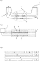
- FIG. 1 shows a stylized door handle 1 for a motor vehicle, which is equipped with a sensor arrangement according to the invention.
- a multilayer board 2 is arranged in the door handle in the handle, that is to say in the area to be gripped when opening the door.
- Several levels with sensor electrode areas are formed on the multilayer board 2, as will be described below.
- a control and evaluation device 3 is coupled to the circuit board 2 and the electrode areas arranged thereon. The control and evaluation device 3 is connected to the vehicle-side central control unit via a cable harness.
- Figure 1 the operating principle is shown, according to which different sensor functions and detection areas are achieved with one and the same multilayer board 2 and also the same electrode areas.
- a detection area 5 is implemented, the field line area of which is in the Figure 1 is indicated with a first broken line representation. If a user reaches into this area inside the door handle, this is detected by the sensor electrode arrangement and a corresponding vehicle function can be triggered.
- the control and evaluation device 3 switches on the sensor electrodes on the multilayer board 2 in accordance with a second scheme, then the sensor electrodes produce a field line 6 that is determined by a second type of broken lines.
- the field lines 5 and 6 are thus offset in time and are not implemented at the same time.
- Figure 2 shows in an enlarged schematic view the control and evaluation device 3 and the coupling to the multilayer board 2 and the electrode areas arranged therein.
- Several electrode planes are formed in the circuit board 2 and metalized electrode areas 4a, 4b, 4c and 4d are arranged.
- electrode 4a is controlled as a sensor electrode, that is, a predetermined voltage is applied to a reference electrode and monitored by the evaluation circuit.
- the electrode 4b then serves as a shield electrode, whereby it is led, for example, to the same potential as the sensor electrode 4a, but changes in capacitance are only monitored in the sensor electrode 4a, but not in the shield electrode 4b.
- the electrode area 4c is kept floating and the electrode area 4d is coupled to ground. In this way, an upwardly directed detection area is implemented (area 5 in Fig. 1 ).
- the detection area can be adjusted downwards (area 6 in Fig. 1 ) to be changed.
- the electrode 4d serves as a sensor electrode with the associated potential and associated evaluation.
- the electrode 4c can be kept potential-free while the electrode 4b as a shielding electrode is at the same potential as the sensor electrode 4d, but without capacitance monitoring.
- the electrode 4a can be coupled to the ground potential according to this scheme.
- Figure 3 shows a further embodiment in which a layer arrangement is shown on a multilayer board in stylized form. Such an arrangement can also be accommodated in a corresponding handle arrangement for the tailgate or the side door of a vehicle.
- Electrodes 11 to 19 formed on four different levels in the multilayer board. These electrode areas are in turn coupled to a control and evaluation device which is not shown here.
- the areas 13, 15 and 16 are coupled to a shield voltage, while the area 11 is connected as a sensor electrode.
- the lateral arrangement of the electrode areas 13 and 15, in addition to the electrode area 16, defines the effect of the sensor electrode 11 like a frame.
- the electrode 18 can be connected as a ground electrode.
- the electrodes are given different functions or other electrode areas are activated.
- the electrode 14 is provided with a shield voltage while the electrode 18 acts as a sensor electrode.
- the electrode areas 17 and 19 are coupled with the same potential as the electrode 14, so that here too the sensor electrode 18 is surrounded by a shielding voltage potential lying on the electrodes 14, 17 and 19.
- the electrode 16 can remain floating in this scheme, while the electrode 12 acts as a ground electrode, for example.
- the electrodes 12, 13, 15, 19 can be activated in order to cover a limited area.
- the electrode 19 and the area for a thumb rest can be placed on the handle. If the detection scheme for thumb rest detection is then activated, electrode 19 serves as a sensor, electrodes 18 and 16 serve as a shield electrode and electrode 15 serves as ground.
- both different electrode areas on the same level of a multilayer board and on different levels of the board are functionally controlled in a time-variable manner.
- Several electrode areas can be combined into functional units. It is essential that some of the electrode areas assume different functions in different control schemes.
Landscapes
- Engineering & Computer Science (AREA)
- Physics & Mathematics (AREA)
- General Physics & Mathematics (AREA)
- Computer Networks & Wireless Communication (AREA)
- Microelectronics & Electronic Packaging (AREA)
- Switches That Are Operated By Magnetic Or Electric Fields (AREA)
- Lock And Its Accessories (AREA)
- Geophysics And Detection Of Objects (AREA)
- Electronic Switches (AREA)
- Measurement Of Length, Angles, Or The Like Using Electric Or Magnetic Means (AREA)
Applications Claiming Priority (2)
| Application Number | Priority Date | Filing Date | Title |
|---|---|---|---|
| DE102014107559.5A DE102014107559A1 (de) | 2014-05-28 | 2014-05-28 | Sensoreinrichtung für ein Kraftfahrzeug |
| PCT/EP2015/060097 WO2015180942A1 (de) | 2014-05-28 | 2015-05-07 | Sensoreinrichtung für ein kraftfahrzeug |
Publications (2)
| Publication Number | Publication Date |
|---|---|
| EP3149855A1 EP3149855A1 (de) | 2017-04-05 |
| EP3149855B1 true EP3149855B1 (de) | 2020-12-16 |
Family
ID=53181277
Family Applications (1)
| Application Number | Title | Priority Date | Filing Date |
|---|---|---|---|
| EP15722998.0A Active EP3149855B1 (de) | 2014-05-28 | 2015-05-07 | Sensoreinrichtung für ein kraftfahrzeug |
Country Status (7)
| Country | Link |
|---|---|
| US (1) | US9948295B2 (ja) |
| EP (1) | EP3149855B1 (ja) |
| JP (1) | JP6546608B2 (ja) |
| KR (1) | KR102247700B1 (ja) |
| CN (1) | CN106414877B (ja) |
| DE (1) | DE102014107559A1 (ja) |
| WO (1) | WO2015180942A1 (ja) |
Families Citing this family (23)
| Publication number | Priority date | Publication date | Assignee | Title |
|---|---|---|---|---|
| DE102012107115A1 (de) * | 2012-08-02 | 2014-02-06 | Brose Fahrzeugteile Gmbh & Co. Kommanditgesellschaft, Hallstadt | Verfahren zur Steuerung eines kapazitiven Einklemmschutzsystems und Einklemmschutzsystem |
| DE102016115109A1 (de) | 2016-08-15 | 2018-02-15 | Huf Hülsbeck & Fürst Gmbh & Co. Kg | Kapazitive Sensorvorrichtung mit verbesserter Störtoleranz |
| JP6851250B2 (ja) * | 2017-04-28 | 2021-03-31 | 株式会社ユーシン | 車両用ドアハンドル装置 |
| US11128298B2 (en) * | 2017-06-27 | 2021-09-21 | Semtech Corporation | Advanced capacitive proximity sensor |
| DE102017121795A1 (de) * | 2017-09-20 | 2019-03-21 | Huf Hülsbeck & Fürst Gmbh & Co. Kg | System und Verfahren zur Detektion einer Aktivierungshandlung |
| EP3741938B1 (en) | 2018-01-17 | 2023-05-31 | Alps Alpine Co., Ltd. | Door handle |
| US10378254B1 (en) * | 2018-05-16 | 2019-08-13 | Ford Global Technologies, Llc | Vehicle door handle having proximity sensors for door control and keypad |
| US10633910B2 (en) | 2018-05-16 | 2020-04-28 | Ford Global Technologies, Llc | Vehicle door having variable speed power assist |
| US11078691B2 (en) | 2018-06-26 | 2021-08-03 | Ford Global Technologies, Llc | Deployable vehicle door handle |
| EP3839180A4 (en) * | 2018-08-15 | 2022-05-11 | Alps Alpine Co., Ltd. | DOOR HANDLE |
| FR3087469B1 (fr) * | 2018-10-19 | 2020-09-25 | Continental Automotive France | Dispositif de detection d'intention de verrouiller ou de deverrouiller une portiere de vehicule automobile et procede associe |
| EP3651361A1 (de) * | 2018-11-06 | 2020-05-13 | Huf Hülsbeck & Fürst GmbH & Co. KG | Sensorvorrichtung |
| DE102018130791A1 (de) | 2018-12-04 | 2020-06-04 | Huf Hülsbeck & Fürst Gmbh & Co. Kg | Fahrzeugtürgriff mit Sensoreinrichtung und drahtloser Kommunikationseinrichtung |
| DE102018130789A1 (de) | 2018-12-04 | 2020-06-04 | Huf Hülsbeck & Fürst Gmbh & Co. Kg | Fahrzeugtürgriff mit Sensoreinrichtung und drahtloser Kommunikationseinrichtung |
| DE102019124221A1 (de) * | 2019-06-11 | 2020-12-17 | Huf Hülsbeck & Fürst Gmbh & Co. Kg | Anordnung |
| DE102019124217A1 (de) * | 2019-06-11 | 2020-12-17 | Huf Hülsbeck & Fürst Gmbh & Co. Kg | Anordnung |
| JP7216963B2 (ja) * | 2019-10-03 | 2023-02-02 | 本田技研工業株式会社 | 静電容量型検知センサ、静電容量型検知センサモジュールおよび静電容量型検知センサを用いた状態判定方法 |
| DE102019132134A1 (de) * | 2019-11-27 | 2021-05-27 | Huf Hülsbeck & Fürst Gmbh & Co. Kg | Vorrichtung für ein Fahrzeug zur Detektion einer Aktivierungshandlung in einem Detektionsbereich |
| DE102020102887A1 (de) * | 2020-02-05 | 2021-08-05 | Huf Hülsbeck & Fürst Gmbh & Co. Kg | Betätigungsvorrichtung mit Verkleidungselement, Fahrzeug, sowie Verfahren |
| WO2021235052A1 (ja) | 2020-05-19 | 2021-11-25 | アルプスアルパイン株式会社 | 静電入力装置 |
| DE102020127438A1 (de) * | 2020-10-19 | 2022-04-21 | Huf Hülsbeck & Fürst Gmbh & Co. Kg | System zur Detektion einer Aktivierungshandlung in einem Aktivierungsbereich für ein Fahrzeug |
| US11573102B2 (en) * | 2020-11-17 | 2023-02-07 | Ford Global Technologies, Llc | Method of manufacturing multi-layer electrode for a capacitive pressure sensor and multi-layer electrodes formed therefrom |
| DE102022203459A1 (de) | 2022-04-06 | 2023-10-12 | Brose Fahrzeugteile Se & Co. Kommanditgesellschaft, Bamberg | Baugruppe eines Fahrzeugs mit einem an einer Fahrzeugtür angeordneten Bedienelement |
Citations (1)
| Publication number | Priority date | Publication date | Assignee | Title |
|---|---|---|---|---|
| DE102008044067A1 (de) * | 2008-11-25 | 2010-05-27 | Huf Hülsbeck & Fürst Gmbh & Co. Kg | Kapazitiver Annäherungssensor mit einer Schirmelektrode und einer Diagnoseelektrode |
Family Cites Families (15)
| Publication number | Priority date | Publication date | Assignee | Title |
|---|---|---|---|---|
| DE19617038C2 (de) | 1996-04-27 | 2000-11-30 | Huf Huelsbeck & Fuerst Gmbh | Schließsystem, insbesondere für Kraftfahrzeuge |
| DE10051055A1 (de) * | 2000-10-14 | 2002-05-02 | Bosch Gmbh Robert | Vorrichtung zum Einleiten eines Öffnungs- und Verriegelungsvorgangs eines Kraftfahrzeugs |
| DE102005055888A1 (de) | 2004-11-23 | 2007-11-15 | Ident Technology Ag | System und dessen Komponenten zur Abwicklung von Signalverarbeitungsabläufen unter Einbeziehung einer zur Präsenzerfassung geeigneten synthetischen Aura |
| US20080088413A1 (en) * | 2004-11-23 | 2008-04-17 | Ident Technology Ag | System and Components Thereof for Carrying Out Signal Processing Operations Including a Synthetic Aura Suitable for Presence Detection |
| EP2017139A1 (en) * | 2007-07-17 | 2009-01-21 | IEE International Electronics & Engineering S.A.R.L. | Occupant detection system for an automotive vehicle |
| FR2942637B1 (fr) | 2009-03-02 | 2015-09-04 | Valeo Securite Habitacle | Poignee d'un ouvrant de vehicule automobile |
| JP2010236329A (ja) * | 2009-03-31 | 2010-10-21 | Fujikura Ltd | 車両用ドア開閉角度制御装置 |
| DE102009002566A1 (de) | 2009-04-22 | 2010-10-28 | Huf Hülsbeck & Fürst Gmbh & Co. Kg | Sensorelektronik in einem Kraftfahrzeugtürgriff |
| US8806572B2 (en) * | 2009-05-30 | 2014-08-12 | Cisco Technology, Inc. | Authentication via monitoring |
| JP4817027B2 (ja) * | 2009-06-16 | 2011-11-16 | 株式会社デンソー | 静電式乗員検知装置 |
| US9051769B2 (en) * | 2009-08-21 | 2015-06-09 | Uusi, Llc | Vehicle assembly having a capacitive sensor |
| DE102010026562A1 (de) * | 2010-07-08 | 2012-01-12 | Hella Kgaa Hueck & Co. | Sensoranordnung zur Erfassung von Umgebungsbedingungen |
| DE102011053314A1 (de) | 2011-09-06 | 2013-03-07 | Huf Hülsbeck & Fürst Gmbh & Co. Kg | Kapazitive Sensoranordnung |
| DE102012107284A1 (de) * | 2012-08-08 | 2014-02-13 | Brose Fahrzeugteile Gmbh & Co. Kommanditgesellschaft, Hallstadt | Steuerungsverfahren und Steuerungssystem für ein Fahrzeugschließelement |
| DE102012109034A1 (de) | 2012-09-25 | 2014-03-27 | Huf Hülsbeck & Fürst Gmbh & Co. Kg | Kraftfahrzeugtürgriff mit Sensorelektronik |
-
2014
- 2014-05-28 DE DE102014107559.5A patent/DE102014107559A1/de not_active Withdrawn
-
2015
- 2015-05-07 WO PCT/EP2015/060097 patent/WO2015180942A1/de active Application Filing
- 2015-05-07 KR KR1020167036083A patent/KR102247700B1/ko active IP Right Grant
- 2015-05-07 EP EP15722998.0A patent/EP3149855B1/de active Active
- 2015-05-07 US US15/313,771 patent/US9948295B2/en active Active
- 2015-05-07 CN CN201580028113.5A patent/CN106414877B/zh active Active
- 2015-05-07 JP JP2016570043A patent/JP6546608B2/ja not_active Expired - Fee Related
Patent Citations (1)
| Publication number | Priority date | Publication date | Assignee | Title |
|---|---|---|---|---|
| DE102008044067A1 (de) * | 2008-11-25 | 2010-05-27 | Huf Hülsbeck & Fürst Gmbh & Co. Kg | Kapazitiver Annäherungssensor mit einer Schirmelektrode und einer Diagnoseelektrode |
Also Published As
| Publication number | Publication date |
|---|---|
| KR20170013911A (ko) | 2017-02-07 |
| WO2015180942A1 (de) | 2015-12-03 |
| JP2017524904A (ja) | 2017-08-31 |
| JP6546608B2 (ja) | 2019-07-17 |
| DE102014107559A1 (de) | 2015-12-03 |
| EP3149855A1 (de) | 2017-04-05 |
| US9948295B2 (en) | 2018-04-17 |
| US20170194960A1 (en) | 2017-07-06 |
| KR102247700B1 (ko) | 2021-05-04 |
| CN106414877B (zh) | 2019-03-08 |
| CN106414877A (zh) | 2017-02-15 |
Similar Documents
| Publication | Publication Date | Title |
|---|---|---|
| EP3149855B1 (de) | Sensoreinrichtung für ein kraftfahrzeug | |
| DE102014016422A1 (de) | Vorrichtung und Verfahren zur Erfassung einer Lenkradberührung | |
| EP3036833B1 (de) | Einrichtung zum berührungslosen betätigen einer fahrzeugtür | |
| WO2016037782A1 (de) | Türgriffanordnung für ein kraftfahrzeug | |
| EP2711488B1 (de) | Kraftfahrzeugtürgriff mit sensorelektronik | |
| DE102019112802A1 (de) | Fahrzeugtür aufweisend ein antriebsassistenzsystem mit variabler geschwindigkeit | |
| DE102014117823A1 (de) | Lenkrad für ein Kraftfahrzeug mit einem Sensorsystem und Verfahren zum Erkennen einer Anwesenheit einer menschlichen Hand in einem Greifbereich eines solchen Lenkrads | |
| EP2828973B1 (de) | Kapazitive sensoranordnung zur schaltung einer türöffnung an einem kraftfahrzeug und zugehöriges verfahren | |
| DE102017120393A1 (de) | Zugangssystem für ein Fahrzeug | |
| DE102013014824A1 (de) | Kapazitiver Sensor für ein Fahrzeug | |
| WO2016102236A1 (de) | Vorrichtung zur berührungslosen betätigung eines verstellbaren fahrzeugteils | |
| WO2012156042A1 (de) | Kraftfahrzeug mit kapazitivem deformationssensor zur kollisionsdetektion | |
| DE102017121795A1 (de) | System und Verfahren zur Detektion einer Aktivierungshandlung | |
| DE112019005884T5 (de) | Sensoranordnung zur kapazitiven Positionserfassung einer Hand an einem Lenkrad | |
| EP3629478B1 (de) | Sensorvorrichtung zur detektion einer aktivierungshandlung bei einem fahrzeug | |
| EP2974023B1 (de) | Kapazitive sensoranordnung mit schirmelektrode | |
| EP2943630B1 (de) | Kapazitive annäherungssensoranordnung an einer tür eines kraftfahrzeugs zum erfassen einer näherungsweise horizontalen annäherungsbewegung einer bedienerhand | |
| DE102012022927A1 (de) | Kapazitiver Näherungssensor | |
| DE102013021823A1 (de) | Vorrichtung zum Erfassen einer elektrodermalen Aktivität einer Person, Lenkrad, Kraftfahrzeug und entsprechendes Verfahren | |
| EP3457569B1 (de) | Auswerteanordnung für eine kapazitive sensorvorrichtung | |
| DE102018131379A1 (de) | Sensorvorrichtung zur Detektion einer Aktivierungshandlung bei einem Fahrzeug | |
| DE102012105363A1 (de) | Sensoranordnung zur Betätigungserfassung an einem Kraftfahrzeug | |
| WO2016026824A1 (de) | Möbel mit sensoreinrichtung | |
| DE102018127683A1 (de) | Sensoranordnung | |
| DE102013019246A1 (de) | Vorrichtung zur berührungslosen Betätigung eines Fahrzeugteils |
Legal Events
| Date | Code | Title | Description |
|---|---|---|---|
| STAA | Information on the status of an ep patent application or granted ep patent |
Free format text: STATUS: THE INTERNATIONAL PUBLICATION HAS BEEN MADE |
|
| PUAI | Public reference made under article 153(3) epc to a published international application that has entered the european phase |
Free format text: ORIGINAL CODE: 0009012 |
|
| STAA | Information on the status of an ep patent application or granted ep patent |
Free format text: STATUS: REQUEST FOR EXAMINATION WAS MADE |
|
| 17P | Request for examination filed |
Effective date: 20170102 |
|
| AK | Designated contracting states |
Kind code of ref document: A1 Designated state(s): AL AT BE BG CH CY CZ DE DK EE ES FI FR GB GR HR HU IE IS IT LI LT LU LV MC MK MT NL NO PL PT RO RS SE SI SK SM TR |
|
| AX | Request for extension of the european patent |
Extension state: BA ME |
|
| DAV | Request for validation of the european patent (deleted) | ||
| DAX | Request for extension of the european patent (deleted) | ||
| STAA | Information on the status of an ep patent application or granted ep patent |
Free format text: STATUS: EXAMINATION IS IN PROGRESS |
|
| 17Q | First examination report despatched |
Effective date: 20190320 |
|
| GRAP | Despatch of communication of intention to grant a patent |
Free format text: ORIGINAL CODE: EPIDOSNIGR1 |
|
| STAA | Information on the status of an ep patent application or granted ep patent |
Free format text: STATUS: GRANT OF PATENT IS INTENDED |
|
| RIC1 | Information provided on ipc code assigned before grant |
Ipc: G07C 9/00 20200101ALI20200903BHEP Ipc: H03K 17/96 20060101ALI20200903BHEP Ipc: H03K 17/955 20060101AFI20200903BHEP Ipc: E05B 81/76 20140101ALI20200903BHEP |
|
| INTG | Intention to grant announced |
Effective date: 20200924 |
|
| GRAS | Grant fee paid |
Free format text: ORIGINAL CODE: EPIDOSNIGR3 |
|
| GRAA | (expected) grant |
Free format text: ORIGINAL CODE: 0009210 |
|
| STAA | Information on the status of an ep patent application or granted ep patent |
Free format text: STATUS: THE PATENT HAS BEEN GRANTED |
|
| AK | Designated contracting states |
Kind code of ref document: B1 Designated state(s): AL AT BE BG CH CY CZ DE DK EE ES FI FR GB GR HR HU IE IS IT LI LT LU LV MC MK MT NL NO PL PT RO RS SE SI SK SM TR |
|
| REG | Reference to a national code |
Ref country code: GB Ref legal event code: FG4D Free format text: NOT ENGLISH |
|
| REG | Reference to a national code |
Ref country code: IE Ref legal event code: FG4D Free format text: LANGUAGE OF EP DOCUMENT: GERMAN |
|
| REG | Reference to a national code |
Ref country code: DE Ref legal event code: R096 Ref document number: 502015014015 Country of ref document: DE |
|
| REG | Reference to a national code |
Ref country code: AT Ref legal event code: REF Ref document number: 1346527 Country of ref document: AT Kind code of ref document: T Effective date: 20210115 |
|
| PG25 | Lapsed in a contracting state [announced via postgrant information from national office to epo] |
Ref country code: NO Free format text: LAPSE BECAUSE OF FAILURE TO SUBMIT A TRANSLATION OF THE DESCRIPTION OR TO PAY THE FEE WITHIN THE PRESCRIBED TIME-LIMIT Effective date: 20210316 Ref country code: FI Free format text: LAPSE BECAUSE OF FAILURE TO SUBMIT A TRANSLATION OF THE DESCRIPTION OR TO PAY THE FEE WITHIN THE PRESCRIBED TIME-LIMIT Effective date: 20201216 Ref country code: RS Free format text: LAPSE BECAUSE OF FAILURE TO SUBMIT A TRANSLATION OF THE DESCRIPTION OR TO PAY THE FEE WITHIN THE PRESCRIBED TIME-LIMIT Effective date: 20201216 Ref country code: GR Free format text: LAPSE BECAUSE OF FAILURE TO SUBMIT A TRANSLATION OF THE DESCRIPTION OR TO PAY THE FEE WITHIN THE PRESCRIBED TIME-LIMIT Effective date: 20210317 |
|
| REG | Reference to a national code |
Ref country code: NL Ref legal event code: MP Effective date: 20201216 |
|
| PG25 | Lapsed in a contracting state [announced via postgrant information from national office to epo] |
Ref country code: LV Free format text: LAPSE BECAUSE OF FAILURE TO SUBMIT A TRANSLATION OF THE DESCRIPTION OR TO PAY THE FEE WITHIN THE PRESCRIBED TIME-LIMIT Effective date: 20201216 Ref country code: SE Free format text: LAPSE BECAUSE OF FAILURE TO SUBMIT A TRANSLATION OF THE DESCRIPTION OR TO PAY THE FEE WITHIN THE PRESCRIBED TIME-LIMIT Effective date: 20201216 Ref country code: BG Free format text: LAPSE BECAUSE OF FAILURE TO SUBMIT A TRANSLATION OF THE DESCRIPTION OR TO PAY THE FEE WITHIN THE PRESCRIBED TIME-LIMIT Effective date: 20210316 |
|
| PG25 | Lapsed in a contracting state [announced via postgrant information from national office to epo] |
Ref country code: NL Free format text: LAPSE BECAUSE OF FAILURE TO SUBMIT A TRANSLATION OF THE DESCRIPTION OR TO PAY THE FEE WITHIN THE PRESCRIBED TIME-LIMIT Effective date: 20201216 Ref country code: HR Free format text: LAPSE BECAUSE OF FAILURE TO SUBMIT A TRANSLATION OF THE DESCRIPTION OR TO PAY THE FEE WITHIN THE PRESCRIBED TIME-LIMIT Effective date: 20201216 |
|
| REG | Reference to a national code |
Ref country code: LT Ref legal event code: MG9D |
|
| PG25 | Lapsed in a contracting state [announced via postgrant information from national office to epo] |
Ref country code: SK Free format text: LAPSE BECAUSE OF FAILURE TO SUBMIT A TRANSLATION OF THE DESCRIPTION OR TO PAY THE FEE WITHIN THE PRESCRIBED TIME-LIMIT Effective date: 20201216 Ref country code: PT Free format text: LAPSE BECAUSE OF FAILURE TO SUBMIT A TRANSLATION OF THE DESCRIPTION OR TO PAY THE FEE WITHIN THE PRESCRIBED TIME-LIMIT Effective date: 20210416 Ref country code: RO Free format text: LAPSE BECAUSE OF FAILURE TO SUBMIT A TRANSLATION OF THE DESCRIPTION OR TO PAY THE FEE WITHIN THE PRESCRIBED TIME-LIMIT Effective date: 20201216 Ref country code: LT Free format text: LAPSE BECAUSE OF FAILURE TO SUBMIT A TRANSLATION OF THE DESCRIPTION OR TO PAY THE FEE WITHIN THE PRESCRIBED TIME-LIMIT Effective date: 20201216 Ref country code: CZ Free format text: LAPSE BECAUSE OF FAILURE TO SUBMIT A TRANSLATION OF THE DESCRIPTION OR TO PAY THE FEE WITHIN THE PRESCRIBED TIME-LIMIT Effective date: 20201216 Ref country code: EE Free format text: LAPSE BECAUSE OF FAILURE TO SUBMIT A TRANSLATION OF THE DESCRIPTION OR TO PAY THE FEE WITHIN THE PRESCRIBED TIME-LIMIT Effective date: 20201216 Ref country code: SM Free format text: LAPSE BECAUSE OF FAILURE TO SUBMIT A TRANSLATION OF THE DESCRIPTION OR TO PAY THE FEE WITHIN THE PRESCRIBED TIME-LIMIT Effective date: 20201216 |
|
| PGFP | Annual fee paid to national office [announced via postgrant information from national office to epo] |
Ref country code: FR Payment date: 20210521 Year of fee payment: 7 |
|
| PG25 | Lapsed in a contracting state [announced via postgrant information from national office to epo] |
Ref country code: PL Free format text: LAPSE BECAUSE OF FAILURE TO SUBMIT A TRANSLATION OF THE DESCRIPTION OR TO PAY THE FEE WITHIN THE PRESCRIBED TIME-LIMIT Effective date: 20201216 |
|
| PGFP | Annual fee paid to national office [announced via postgrant information from national office to epo] |
Ref country code: GB Payment date: 20210526 Year of fee payment: 7 |
|
| REG | Reference to a national code |
Ref country code: DE Ref legal event code: R097 Ref document number: 502015014015 Country of ref document: DE |
|
| PG25 | Lapsed in a contracting state [announced via postgrant information from national office to epo] |
Ref country code: IS Free format text: LAPSE BECAUSE OF FAILURE TO SUBMIT A TRANSLATION OF THE DESCRIPTION OR TO PAY THE FEE WITHIN THE PRESCRIBED TIME-LIMIT Effective date: 20210416 |
|
| PLBE | No opposition filed within time limit |
Free format text: ORIGINAL CODE: 0009261 |
|
| STAA | Information on the status of an ep patent application or granted ep patent |
Free format text: STATUS: NO OPPOSITION FILED WITHIN TIME LIMIT |
|
| PG25 | Lapsed in a contracting state [announced via postgrant information from national office to epo] |
Ref country code: IT Free format text: LAPSE BECAUSE OF FAILURE TO SUBMIT A TRANSLATION OF THE DESCRIPTION OR TO PAY THE FEE WITHIN THE PRESCRIBED TIME-LIMIT Effective date: 20201216 Ref country code: AL Free format text: LAPSE BECAUSE OF FAILURE TO SUBMIT A TRANSLATION OF THE DESCRIPTION OR TO PAY THE FEE WITHIN THE PRESCRIBED TIME-LIMIT Effective date: 20201216 |
|
| 26N | No opposition filed |
Effective date: 20210917 |
|
| PG25 | Lapsed in a contracting state [announced via postgrant information from national office to epo] |
Ref country code: ES Free format text: LAPSE BECAUSE OF FAILURE TO SUBMIT A TRANSLATION OF THE DESCRIPTION OR TO PAY THE FEE WITHIN THE PRESCRIBED TIME-LIMIT Effective date: 20201216 Ref country code: DK Free format text: LAPSE BECAUSE OF FAILURE TO SUBMIT A TRANSLATION OF THE DESCRIPTION OR TO PAY THE FEE WITHIN THE PRESCRIBED TIME-LIMIT Effective date: 20201216 |
|
| REG | Reference to a national code |
Ref country code: CH Ref legal event code: PL |
|
| PG25 | Lapsed in a contracting state [announced via postgrant information from national office to epo] |
Ref country code: MC Free format text: LAPSE BECAUSE OF FAILURE TO SUBMIT A TRANSLATION OF THE DESCRIPTION OR TO PAY THE FEE WITHIN THE PRESCRIBED TIME-LIMIT Effective date: 20201216 Ref country code: LI Free format text: LAPSE BECAUSE OF NON-PAYMENT OF DUE FEES Effective date: 20210531 Ref country code: LU Free format text: LAPSE BECAUSE OF NON-PAYMENT OF DUE FEES Effective date: 20210507 Ref country code: CH Free format text: LAPSE BECAUSE OF NON-PAYMENT OF DUE FEES Effective date: 20210531 |
|
| REG | Reference to a national code |
Ref country code: BE Ref legal event code: MM Effective date: 20210531 |
|
| PG25 | Lapsed in a contracting state [announced via postgrant information from national office to epo] |
Ref country code: SI Free format text: LAPSE BECAUSE OF FAILURE TO SUBMIT A TRANSLATION OF THE DESCRIPTION OR TO PAY THE FEE WITHIN THE PRESCRIBED TIME-LIMIT Effective date: 20201216 |
|
| PG25 | Lapsed in a contracting state [announced via postgrant information from national office to epo] |
Ref country code: IE Free format text: LAPSE BECAUSE OF NON-PAYMENT OF DUE FEES Effective date: 20210507 |
|
| PG25 | Lapsed in a contracting state [announced via postgrant information from national office to epo] |
Ref country code: IS Free format text: LAPSE BECAUSE OF FAILURE TO SUBMIT A TRANSLATION OF THE DESCRIPTION OR TO PAY THE FEE WITHIN THE PRESCRIBED TIME-LIMIT Effective date: 20210416 |
|
| REG | Reference to a national code |
Ref country code: AT Ref legal event code: MM01 Ref document number: 1346527 Country of ref document: AT Kind code of ref document: T Effective date: 20210507 |
|
| PG25 | Lapsed in a contracting state [announced via postgrant information from national office to epo] |
Ref country code: BE Free format text: LAPSE BECAUSE OF NON-PAYMENT OF DUE FEES Effective date: 20210531 |
|
| PG25 | Lapsed in a contracting state [announced via postgrant information from national office to epo] |
Ref country code: AT Free format text: LAPSE BECAUSE OF NON-PAYMENT OF DUE FEES Effective date: 20210507 |
|
| GBPC | Gb: european patent ceased through non-payment of renewal fee |
Effective date: 20220507 |
|
| PG25 | Lapsed in a contracting state [announced via postgrant information from national office to epo] |
Ref country code: FR Free format text: LAPSE BECAUSE OF NON-PAYMENT OF DUE FEES Effective date: 20220531 |
|
| PG25 | Lapsed in a contracting state [announced via postgrant information from national office to epo] |
Ref country code: HU Free format text: LAPSE BECAUSE OF FAILURE TO SUBMIT A TRANSLATION OF THE DESCRIPTION OR TO PAY THE FEE WITHIN THE PRESCRIBED TIME-LIMIT; INVALID AB INITIO Effective date: 20150507 Ref country code: GB Free format text: LAPSE BECAUSE OF NON-PAYMENT OF DUE FEES Effective date: 20220507 |
|
| P01 | Opt-out of the competence of the unified patent court (upc) registered |
Effective date: 20230507 |
|
| PG25 | Lapsed in a contracting state [announced via postgrant information from national office to epo] |
Ref country code: CY Free format text: LAPSE BECAUSE OF FAILURE TO SUBMIT A TRANSLATION OF THE DESCRIPTION OR TO PAY THE FEE WITHIN THE PRESCRIBED TIME-LIMIT Effective date: 20201216 |
|
| PGFP | Annual fee paid to national office [announced via postgrant information from national office to epo] |
Ref country code: DE Payment date: 20230531 Year of fee payment: 9 |
|
| PG25 | Lapsed in a contracting state [announced via postgrant information from national office to epo] |
Ref country code: MK Free format text: LAPSE BECAUSE OF FAILURE TO SUBMIT A TRANSLATION OF THE DESCRIPTION OR TO PAY THE FEE WITHIN THE PRESCRIBED TIME-LIMIT Effective date: 20201216 |