EP3149532B1 - Functionally integrated laser scanning microscope - Google Patents
Functionally integrated laser scanning microscope Download PDFInfo
- Publication number
- EP3149532B1 EP3149532B1 EP15726562.0A EP15726562A EP3149532B1 EP 3149532 B1 EP3149532 B1 EP 3149532B1 EP 15726562 A EP15726562 A EP 15726562A EP 3149532 B1 EP3149532 B1 EP 3149532B1
- Authority
- EP
- European Patent Office
- Prior art keywords
- detection
- operating mode
- illumination
- path
- laser scanning
- Prior art date
- Legal status (The legal status is an assumption and is not a legal conclusion. Google has not performed a legal analysis and makes no representation as to the accuracy of the status listed.)
- Active
Links
Images


Classifications
-
- G—PHYSICS
- G02—OPTICS
- G02B—OPTICAL ELEMENTS, SYSTEMS OR APPARATUS
- G02B21/00—Microscopes
- G02B21/0004—Microscopes specially adapted for specific applications
- G02B21/002—Scanning microscopes
- G02B21/0024—Confocal scanning microscopes (CSOMs) or confocal "macroscopes"; Accessories which are not restricted to use with CSOMs, e.g. sample holders
- G02B21/0032—Optical details of illumination, e.g. light-sources, pinholes, beam splitters, slits, fibers
-
- G—PHYSICS
- G02—OPTICS
- G02B—OPTICAL ELEMENTS, SYSTEMS OR APPARATUS
- G02B21/00—Microscopes
- G02B21/0004—Microscopes specially adapted for specific applications
- G02B21/002—Scanning microscopes
-
- G—PHYSICS
- G02—OPTICS
- G02B—OPTICAL ELEMENTS, SYSTEMS OR APPARATUS
- G02B21/00—Microscopes
- G02B21/0004—Microscopes specially adapted for specific applications
- G02B21/002—Scanning microscopes
- G02B21/0024—Confocal scanning microscopes (CSOMs) or confocal "macroscopes"; Accessories which are not restricted to use with CSOMs, e.g. sample holders
- G02B21/0036—Scanning details, e.g. scanning stages
- G02B21/004—Scanning details, e.g. scanning stages fixed arrays, e.g. switchable aperture arrays
-
- G—PHYSICS
- G02—OPTICS
- G02B—OPTICAL ELEMENTS, SYSTEMS OR APPARATUS
- G02B21/00—Microscopes
- G02B21/0004—Microscopes specially adapted for specific applications
- G02B21/002—Scanning microscopes
- G02B21/0024—Confocal scanning microscopes (CSOMs) or confocal "macroscopes"; Accessories which are not restricted to use with CSOMs, e.g. sample holders
- G02B21/0052—Optical details of the image generation
- G02B21/0076—Optical details of the image generation arrangements using fluorescence or luminescence
-
- G—PHYSICS
- G02—OPTICS
- G02B—OPTICAL ELEMENTS, SYSTEMS OR APPARATUS
- G02B21/00—Microscopes
- G02B21/0004—Microscopes specially adapted for specific applications
- G02B21/002—Scanning microscopes
- G02B21/0024—Confocal scanning microscopes (CSOMs) or confocal "macroscopes"; Accessories which are not restricted to use with CSOMs, e.g. sample holders
- G02B21/008—Details of detection or image processing, including general computer control
-
- G—PHYSICS
- G02—OPTICS
- G02B—OPTICAL ELEMENTS, SYSTEMS OR APPARATUS
- G02B21/00—Microscopes
- G02B21/36—Microscopes arranged for photographic purposes or projection purposes or digital imaging or video purposes including associated control and data processing arrangements
- G02B21/361—Optical details, e.g. image relay to the camera or image sensor
-
- G—PHYSICS
- G02—OPTICS
- G02B—OPTICAL ELEMENTS, SYSTEMS OR APPARATUS
- G02B21/00—Microscopes
- G02B21/36—Microscopes arranged for photographic purposes or projection purposes or digital imaging or video purposes including associated control and data processing arrangements
- G02B21/365—Control or image processing arrangements for digital or video microscopes
- G02B21/367—Control or image processing arrangements for digital or video microscopes providing an output produced by processing a plurality of individual source images, e.g. image tiling, montage, composite images, depth sectioning, image comparison
Definitions
- the invention relates to a function-integrated laser scanning microscope designed to scan a sample with laser illumination, optionally in a confocal, line or wide-field operating mode.
- Confocal laser scanning microscopes are known per se.
- a sample area to be examined is scanned with a laser beam focused to a point, the properties of the light reflected by the sample substance or emitted by fluorescence are measured for all scanned locations, and an image of the sample area is generated from the measurement results.
- spinning disc microscopy Another possibility of increasing the rate of obtaining confocal images has been created with what is known as spinning disc microscopy (SDM).
- SDM spinning disc microscopy
- FLIM fluorescence-lifetime imaging microscopy
- FRET Förster resonance energy transfer experiments
- FCS fluorescence correlation spectroscopy
- spectral imaging is also essential in order to be able to clearly distinguish multiple colors of the sample from one another and to be able to analyze switching processes in the cell.
- Spectral imaging by means of spinning disc microscopy or by means of wide field microscopes has been discussed many times in the literature, but has so far not been able to establish itself commercially.
- a device combination proposed for confocal to wide-field microscopy is, for example, the confocal laser scanning microscope C2 from the manufacturer Nikon, which is modular is made up of various optical components which, depending on the application, can be exchanged and coupled to one another.
- the object of the invention is to provide a laser scanning microscope which has various preselectable operating modalities which make it possible to configure the microscope in a simple manner for the respective experimental requirements.
- controllable optical assemblies are connected via a command input device to a control circuit which is designed to switch from the current to a different operating mode, and there is hardware and software for generating images of the sample from the electronic image signals emitted by the detection device.
- laser illumination includes both point, line and field illumination of the sample or of a region of the sample to be examined.
- the point, line or field-shaped configuration of the illumination light takes place by means of the controllable optical elements depending on the respectively specified operating mode.
- the above-mentioned image recording rates of up to 30 fps or greater than 100 fps are each related to 512 lines per image, with the assumption that the image recording rate is limited due to the line speed.
- the image acquisition rate when generating parallel 2-dimensional images is initially given by the specific geometry of the image sensor, but a larger area of the sample can also be recorded using a mosaic method.
- the change in the beam guidance as a function of the respectively selected operating mode is provided by coupling the detection radiation into different detection paths by means of a controllable optical switching element.
- the detection paths differ in the optical assemblies located in the beam path and / or in the position of at least one image plane and one pupil plane.
- One detection path is permanently assigned to an operating mode.
- the detection radiation is passed through and influenced by at least one optical assembly fixed to the frame in the beam path, while in a second detection path the detection radiation is diverted around this optical assembly in order to avoid interference.
- an image plane is formed at a defined position in the first detection path, and a pupil plane instead of the image plane in the second detection path.
- a lens array for example, is provided as the optical assembly fixed to the frame.
- the first detection path is preferably assigned to the confocal operating mode, and the second detection path is assigned to the line and wide-field operating modes.
- the detection beam path there can be a second optical switching element with which - depending on the switching position - the detection radiation coming via the respective detection path is coupled into the common detection device.
- a switching mirror is provided as the first switching element, for example, and a movable prism can be provided as the second switching element.
- the optical switching elements are connected to the control circuit, which specifies the switching positions as a function of the respective operating mode.
- the control circuit is coupled to the command input device for switching over the operating modes.
- the illumination beam path of the laser scanning microscope according to the invention has an illumination scanner for moving the laser illumination over the objective pupil and / or for adapting the illumination beam guidance to the respectively set operating mode.
- the movement pattern or the movement sequence depends on the selected operating mode, i.e.
- the lighting scanner is controlled depending on the operating mode.
- controllable optical assemblies for varying the beam guidance as a function of the respectively selected operating mode are provided in the illumination beam path and are connected to the control circuit.
- the function and purpose of the swivel-in assemblies are explained in more detail below using exemplary embodiments.
- the pivoting in and out is initiated by the control circuit as a function of the specified operating mode.
- the detection device common to all operating modes has an optoelectronic image sensor, the sensor pixels of which can be individually controlled for the purpose of activation and deactivation.
- the control of the image sensor or the individual sensor pixels is initiated by the control circuit as a function of the specified operating mode.
- the image sensor has a two-dimensional arrangement of the sensor pixels so that, in accordance with spinning disc technology, it is possible to acquire fast and sample-saving confocal images by paralleling excitation and detection with a large number of spots.
- each sensor pixel can be activated or deactivated individually by means of the control circuit, several sensor pixels can be variably combined in groups and a plurality of pixel regions to be read out independently of one another on the sensor surface are freely programmable.
- each pixel of the two-dimensional sensor matrix registers the intensity of the emission assigned to a sample location.
- the data read out by the sensor thus result in a monochrome partial image.
- the emitted intensity of the assigned sample location within a defined spectral band can be taken from each sensor pixel via an additional optical arrangement.
- the spectral information is distributed essentially orthogonally to the location information over the sensor surface. This enables spectral imaging in these operating modes.
- a matrix of avalanche photodiodes is preferably considered as the image sensor.
- hybrid detectors or matrix arrangements of photomultipliers, for example, are also suitable as image sensors.
- the idea of the invention consists, inter alia, in the implementation of multifocal imaging, line imaging and wide-field imaging with one and the same image sensor. You can switch between these modes quickly and easily by controlling a few variable optical assemblies and also adapting the image sensor through immediate reprogramming.
- the laser scanning microscope according to the invention is preferably designed for fluorescence microscopy with the illuminating light as excitation radiation and the fluorescence caused thereby as detection radiation.
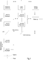
- FIG.1 The illustration shown clarifies the basic structure of the laser scanning microscope according to the invention, for example designed for fluorescence microscopy.
- a laser unit and a detection device are provided which are programmable with regard to the confocal, line or wide field operating mode, i. it is not necessary to exchange different laser units and / or detection devices when changing the operating modes.
- the illumination and detection beam path is also retained when the operating modes are changed, only a few variably controllable optical assemblies are present in the beam paths that are designed to adapt the beam guidance (cf. Fig. 2 to Fig. 4 ).
- the controllable optical assemblies themselves, the basic optical elements of the microscope system such as the main color splitter HFT and beam deflecting elements as well as the objective remain in their positions, regardless of the selected operating mode.
- the sample can be moved relative to the objective in the coordinates x, y, z by means of a preferably motorized sample table.
- a command input device is connected to the control circuit and is used for manual specification of the respectively desired operating mode.
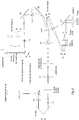
- Fig. 2 the beam path for the illumination and detection in the imaging mode in confocal or multi-confocal microscopy is shown, which enables frame rates of approx. 30 fps with optimal spectral functionality.
- the controllable optical assemblies in the illumination beam path up to the main color splitter HFT are a swivel-in cylinder lens (alternatively also a Powel lens), an illumination scanner S1 and an interchangeable lens with a single lens L3 and a telescope made up of lenses L1, L2.
- the individual lens L3 is pivoted into the illuminating beam path.
- the illumination light reflected at the main color splitter HFT is deflected in the direction of the objective by the switching mirror and the system scanner S2, both of which are in conjugate planes to the pupil of the objective.
- the multi-confocal operating mode a large number of laser beams are coupled into the system, which are spread out in the form of a fan with a fixed angular relationship to one another. This fan is perpendicular to the plane of the drawing Fig. 2 aligned, ie the multitude of laser beams lie one behind the other in the plane of the drawing.
- the angular relationship of the rays to one another is adapted to the pitch of the lens array.
- the illumination scanner S1 is positioned so that the beam bundles are guided along the axis of the following optics.
- the lens system made up of L3 and L4 images the lighting scanner S1 on the switching mirror, while L5 images the switching mirror on the system scanner S2.
- the illumination scanner S1 and the switching mirror are thus conjugated to the objective pupil.
- each partial beam thus generates a spot in the object space, the spots being arranged along a line.
- the spot pattern is moved over the sample by means of the system scanner S2.
- the number of spots is set by activating or masking partial beams. Means for generating the large number of partial beams are known from the prior art and do not require any more detailed explanation here.
- the main color splitter HFT which can be designed as a notch filter, for example, is used to separate the illumination and detection light.
- a switching mirror and a lens L6 are arranged along the detection beam path and produce an image plane in which there is a slit diaphragm (variable with respect to the two other operating modes by control).
- the image plane of lens L6 is also on the scanner side Focal plane of a subsequent lens array and pinhole optics with a pinhole (variable with respect to the other two operating modes by control).
- the pinhole is arranged in the image plane of the lens L7 on the sensor side.
- a lens system from L8 to L10, which images the emission on a detection device, is arranged downstream of the pinhole.
- a movable prism optimizes the position of the emission from the sample on the sensor matrix depending on the set operating mode.
- the emission from the positions of the laser illumination in the object space is descanned by means of the system scanner S2 and aligned with the switching mirror along the optical axis of the pinhole optics.
- the combination of switching mirror and main color splitter HFT is set such that each partial beam is collimated by a lens assigned to it in the lens array. Since the partial beams are guided telecentrically around the intermediate image in front of the lens array in the position of the slit diaphragm, a transformation to parallel beam guidance takes place through the lens array.
- the partial beams are subsequently imaged through the pinhole onto the image sensor of the detection device.
- the detection device is preferably equipped with an avalanche photodiode array as an image sensor.
- the in Fig. 2 The confocal operating mode shown basically corresponds to the basic mode of the function-integrated laser scanning microscope according to the invention. In this mode, how out Fig. 2 can be seen, the detection radiation passed through the lens array. Laser spots lying on the respective optical axes of the lens array are collimated as partial beams by means of the lens array and telecentrically guided to lens L7, which focuses the telecentric, collimated partial beams on a common point in the pinhole plane. Only this one pinhole is therefore required to filter confocally on all partial beams, while the aperture of the pinhole is reduced to the desired size, in this operating mode, for example, to an opening diameter that corresponds to an Airy unit.
- the lens array In the other two operating modes, in which a semiconfocal or field-scanning imaging is carried out by means of linear or areal excitation, the lens array would interfere in the beam path because it strongly segmented the image field. In these cases, the detection radiation is therefore directed into a separate detection path with the switching mirror and thus guided past the lens array.
- the pinhole plane as the rear focal plane of the lens L7 is conjugated to the objective pupil in the two other operating modes, i.e. in the field or line configuration (cf. Fig. 3 and Fig. 4 ).
- the lens system made up of L8 and L9 is a relay system that maps the pinhole level into the interface to the detector optics.
- the lens L10 symbolizes the detector optics.
- the reflection of the illumination beams in the detection beam path between the lens array and the pinhole optics can take place. Then the partial beams are already to be guided in parallel in the illumination beam path.
- Fig. 3 shows an example for the configuration of the illumination and detection beam path in the operating mode of wide-field or field-scan microscopy.
- the telescope consisting of the lenses L1, L2 is pivoted into the illuminating beam path instead of the individual lens L3.
- the illumination light reflected by the main color splitter HFT is deflected in the direction of the lens by the switching mirror and the system scanner S2, but a laser focus is created on both, which is moved over the pupil plane with the fastest possible scanning movement of the illumination scanner S1.
- the fluorescence excited in this way in the entire field of the objective illuminates the objective pupil completely on the way back from the sample.
- the objective pupil is imaged in the conjugate planes on the system scanner S2 and the switching mirror.
- the switching mirror is set by control in such a way that the transmittable field, transmitted by the main color splitter HFT, is directed off-axis past the lens array on a separate detection path.
- variable pinhole arranged in the detection beam path and the variable slit diaphragm in front of the lens array are wide open in the operating mode shown here.
- the system scanner S2 determines the position of the imaged partial field in the available object field of the microscope objective by means of an offset angle set by control.
- a field stop (not shown) in the first intermediate image plane behind the objective can also be moved together with the scanner offset in order to prevent or minimize overexposure of sample areas outside the detectable object field.
- an illumination zoom can be provided at this point in order to limit the numerical aperture (NA) of the illumination and thus to control the size of the illuminated object field.
- NA numerical aperture
- An adaptation of the NA can, however, also be provided in the interchangeable optics and designed in such a way that the transmittable field is completely illuminated.
- Fig. 4 shows the beam path for the line scan mode.
- the cylinder lens is placed in the illumination beam path, so that a linear light distribution is created on the illumination scanner S1, the illumination scanner S1 being in the focal plane of the cylinder lens.
- the interchangeable optics are positioned so that the individual lens L3 is located in the illumination beam path.
- a pupil plane lies on the illumination scanner S1, the switching mirror, the system scanner S2 and in the lens.
- the objective then generates a line focus in the object space, which is scanned with the system scanner S2 perpendicular to the line direction and positioned using offset angles.
- the emission from the line focus is descanned by the system scanner S2 and directed past the lens array when the switching mirror is in the appropriate position.
- the slit diaphragm in the intermediate image in front of the lens array is pulled to the desired width in order to achieve semi-confocal detection.
- the downstream pinhole is open to the maximum.
- the movable prism pulls the center of the line distribution onto the axis of the image sensor of the detection optics. In the case of the line scan mode, the image sensor lies in an image plane conjugated to the slit.
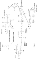
- the switching of the detection beam path necessary for b) and c) can for example be done by the displaceable prism. This is in Fig. 5 and Fig. 6 shown schematically.
- Fig. 5 the optical path from the displaceable prism to the sensor plane is shown in more detail using an example for multifocal operation.
- Fig.5a) represents a top view, against it
- Fig.5b) a side view of the detection beam path.
- Downstream of the displaceable prism are two relay optics made of the lens pairs L11 / L12 and L13 / 14, which image the emission in the sensor plane.
- a lens array is located between the two relay optics, which in turn is fixed to the frame.
- the displaceable prism is set in such a way that the emission is guided through the lens array.
- the partial beams are now collimated between the lenses L13 and L14 and guided in a fixed angular relationship to one another.
- a dispersing element for example a prism, which splits the emission guided in the partial beams into its spectral components.
- the direction of dispersion is advantageously perpendicular to the fan spanned by the partial beams.
- Lens L14 maps the spectrally dispersed emission onto the sensor.
- the spots and spectrum are advantageously arranged perpendicular to one another.
- the sensor now lies in a plane conjugate to the sample, regardless of the selected operating mode.
- the detection radiation would be guided past this lens array.
- the sliding prism In the line-scanning operating mode, the sliding prism is, as in Fig. 6 shown, adjusted so that the emission is guided past the lens array.
- the spectral deflections on the image sensor are used for the multi-confocal operating mode ( Fig. 5 ) and the line-scanning operating mode ( Fig. 6 ) generated with the same dispersion element.
- the position of the spectrum on the sensor matrix is made, if necessary, by rotating the dispersion optics, as shown in FIG Fig. 5 in terms of multiconfocal mode and off Fig. 6 in relation to the line scan mode.
- the dispersion element is removed from the beam path.
- Switching between pupil and field can in principle be done with pivotable Bertrand lenses or by means of switchable light paths.
- elements for switching are mirrors for angular separation (preferably MEMS), flat plates for lateral separation or prisms for both.
Description
Die Erfindung betrifft ein funktionsintegriertes Laser-Scanning-Mikroskop, ausgebildet zur Abtastung einer Probe mit einer Laserbeleuchtung wahlweise in einem Konfokal-, Linien- oder Weitfeld-Betriebsmodus.The invention relates to a function-integrated laser scanning microscope designed to scan a sample with laser illumination, optionally in a confocal, line or wide-field operating mode.
Konfokale Laser-Scanning-Mikroskope sind an sich bekannt. Hierbei wird ein zu untersuchender Probenbereich mit einem zu einem Punkt fokussierten Laserstrahl abgerastert, für alle abgerasterten Orte werden mittels Bildsensoren die Eigenschaften des Lichtes gemessen, das von der Probensubstanz reflektiert oder durch Fluoreszenz abgegeben wird, und aus den Messergebnissen wird ein Bild des Probenbereiches erzeugt.Confocal laser scanning microscopes are known per se. Here, a sample area to be examined is scanned with a laser beam focused to a point, the properties of the light reflected by the sample substance or emitted by fluorescence are measured for all scanned locations, and an image of the sample area is generated from the measurement results.
Bei der Anwendung der Laser-Scanning-Mikroskopie in der biomedizinischen Forschung rückte in den vergangenen Jahren die Lebendzellforschung immer stärker in den Vordergrund des wissenschaftlichen Interesses, beispielsweise zwecks Studium metabolischer Prozesse in Zellen oder zur Analyse der Wirkung von Pharmaka auf die Zellphysiologie. Dabei kommt der Fluoreszenzmikroskopie eine besondere Bedeutung zu, da sie subzellulare optische Beobachtung mit hoher Differenzierbarkeit verschiedener Organellen ermöglicht und sich das Mikroskop vom reinen Bildgebungssystem zu einem wichtigen Messwerkzeug entwickelt. Das Studium von lebenden Zellen stellt jedoch hohe Anforderungen an das Mikroskopsystem. Zum einen muss die Datenakquise sehr schnell erfolgen, um den zeitlichen Ablauf biologischer Prozesse verfolgen zu können, zum anderen ist die Lebenserhaltung der Zelle zu gewährleisten bzw. die Störung ihres Metabolismus gering zu halten. Das erfordert einen möglichst geringen Lichteintrag in die Zelle bei der Anregung der fluoreszierenden Moleküle, der aber das Signal-Rausch-Verhältnis (SNR) nicht beeinträchtigen sollte, damit die gewünschten Informationen möglichst schnell und genau akquiriert werden können.In recent years, when laser scanning microscopy is used in biomedical research, live cell research has moved more and more into the foreground of scientific interest, for example for the study of metabolic processes in cells or for the analysis of the effects of pharmaceuticals on cell physiology. Fluorescence microscopy is particularly important here, as it enables subcellular optical observation with a high degree of differentiation between different organelles and the microscope is developing from a pure imaging system into an important measuring tool. However, studying living cells places high demands on the microscope system. On the one hand, the data acquisition has to take place very quickly in order to be able to follow the chronological sequence of biological processes; on the other hand, the survival of the cell must be guaranteed and the disturbance of its metabolism kept to a minimum. This requires the lowest possible amount of light entering the cell when the fluorescent molecules are excited, but this reduces the signal-to-noise ratio (SNR) should not affect so that the desired information can be acquired as quickly and accurately as possible.
Die Erfüllung dieser teils einander konträren Forderungen sind eine bedeutende Herausforderung bei der Weiterentwicklung der Laser-Scanning-Mikroskopie.The fulfillment of these partly contradicting requirements is a major challenge in the further development of laser scanning microscopy.
Die Schwierigkeiten liegen darin, dass die konfokale Bildgebung aufgrund der punktweise sequentiellen Datenerhebung in ihrer Bildaufnahmerate limitiert ist. Zwar lässt sich die Bildaufnahmerate durch schnellere Abtastung mittels resonanter Galvanometerscanner erhöhen, jedoch wird dadurch die Akkumulationszeit pro Bildsensor entsprechend verringert. Um trotzdem das gewünschte Signal-Rausch-Verhältnis zu erreichen, muss intensiver beleuchtet werden, was wiederum die toxische Belastung der lebenden Probe erhöht.The difficulties are that confocal imaging is limited in its image acquisition rate due to the point-wise sequential data acquisition. Although the image recording rate can be increased by faster scanning using a resonant galvanometer scanner, this reduces the accumulation time per image sensor accordingly. In order to still achieve the desired signal-to-noise ratio, the lighting must be more intensive, which in turn increases the toxic load on the living sample.
Eine andere Möglichkeit, die Rate bei der Gewinnung konfokaler Bilder zu erhöhen, ist mit der sogenannten Spinning-Disc-Mikroskopie (SDM) geschaffen worden. Hier wird mittels zweier gekoppelt rotierender Scheiben, wovon die erste Scheibe Mikrolinsen trägt und auf der zweiten den Mikrolinsen zugeordnete Konfokalblenden angeordnet sind, durch Parallelisierung eine erhebliche Erhöhung der Bildaufnahmerate erreicht. Allerdings ist die Höhe der Bildaufnahmerate durch die Eigenschaften der Bildsensoren limitiert. Außerdem sind Spinning-Disc-Mikroskope auf die Funktionalität der Bildgebung spezialisiert, darüber hinaus gehende Messaufgaben wie Fluorescence-lifetime imaging microscopy (FLIM), Förster Resonanz EnergieTransfer-Experimente (FRET) oder Fluoreszenzkorrelationsspektroskopie (FCS) sind nicht oder ungenügend anwendbar.Another possibility of increasing the rate of obtaining confocal images has been created with what is known as spinning disc microscopy (SDM). Here, by means of two coupled rotating disks, of which the first disk carries microlenses and the second confocal diaphragms associated with the microlenses are arranged, a considerable increase in the image recording rate is achieved through parallelization. However, the image recording rate is limited by the properties of the image sensors. In addition, spinning disc microscopes are specialized in imaging functionality; additional measurement tasks such as fluorescence-lifetime imaging microscopy (FLIM), Förster resonance energy transfer experiments (FRET) or fluorescence correlation spectroscopy (FCS) cannot be used or are insufficient.
Schließlich ist auch eine spektrale Bildgebung unumgänglich, um Mehrfachfärbungen der Probe sauber voneinander unterscheiden und Schaltprozesse in der Zelle analysieren zu können. Die spektrale Bildgebung mittels Spinning-Disc-Mikroskopie oder mittels Weitfeldmikroskopen wurde in der Literatur zwar vielfach diskutiert, konnte sich aber kommerziell bisher nicht durchsetzen.Finally, spectral imaging is also essential in order to be able to clearly distinguish multiple colors of the sample from one another and to be able to analyze switching processes in the cell. Spectral imaging by means of spinning disc microscopy or by means of wide field microscopes has been discussed many times in the literature, but has so far not been able to establish itself commercially.
Daraus ergibt sich, dass nach Stand der Technik zwar einzelne, jeweils auf besondere Anwendungen spezialisierte Laser-Scanning-Mikrokopsysteme verfügbar sind, jedoch keine funktionsintegrierten Systeme, die umfassendere, universellere Forderungen erfüllen und dadurch vielfältigere Applikationen ermöglichen.It follows from this that, according to the state of the art, individual laser scanning microscope systems, each specializing in particular applications, are available, but no function-integrated systems that meet more comprehensive, more universal requirements and thus enable more diverse applications.
Eine für die Konfokal- bis zur Weitfeld-Mikroskopie vorgeschlagene Gerätekombination ist beispielsweise das konfokale Laser-Scanning-Mikroskop C2 des Herstellers Nikon, das modular aus diversen optischen Komponenten aufgebaut ist, die je nach Applikation gegeneinander auszutauschen und miteinander koppelbar sind.A device combination proposed for confocal to wide-field microscopy is, for example, the confocal laser scanning microscope C2 from the manufacturer Nikon, which is modular is made up of various optical components which, depending on the application, can be exchanged and coupled to one another.
Das zu lösende Problem besteht jedoch immer noch in der Verfügbarkeit von Konfokal-, Linien- oder Weitfeld-Betriebsmodus noch während der Beobachtung einer Probe, ohne erst zeitaufwändig den Austausch von Modulen oder Geräteumbauten vornehmen zu müssen.The problem to be solved, however, is still the availability of confocal, line or wide-field operating mode while a sample is being observed, without first having to replace modules or device conversions in a time-consuming manner.
Davon ausgehend besteht die Aufgabe der Erfindung darin, ein Laser-Scanning-Mikroskop anzugeben, das über verschiedene vorwählbare Betriebsmodalitäten verfügt, die es ermöglichen, das Mikroskop in einfacher Weise auf die jeweiligen experimentellen Erfordernisse zu konfigurieren.Proceeding from this, the object of the invention is to provide a laser scanning microscope which has various preselectable operating modalities which make it possible to configure the microscope in a simple manner for the respective experimental requirements.
Diese Aufgabe wird mit einem Laser-Scanning-Mikroskop der eingangs genannten Art gelöst, welches umfasst:
- eine Laserlichtquelle, einen Beleuchtungs- und Detektionsstrahlengang, eine Detektionseinrichtung und mindestens ein Objektiv, jeweils ausgebildet zur Nutzung für jeden der wählbaren Betriebsmodi, wobei
- der Beleuchtungs- und Detektionsstrahlengang optische Mittel zur Konfiguration der Laserbeleuchtung, mindestens einen Scanner zur Abtastung der Probe mit der Laserbeleuchtung, und einen Strahlteiler zur Trennung von Beleuchtungs- und Detektionslicht umfasst, und
- im Detektionsstrahlengang steuerbare optische Elemente zur Änderung der Strahlführung in Abhängigkeit vom jeweils gewählten Betriebsmodus vorgesehen sind.
- a laser light source, an illumination and detection beam path, a detection device and at least one objective, each designed for use for each of the selectable operating modes, wherein
- the illumination and detection beam path comprises optical means for configuring the laser illumination, at least one scanner for scanning the sample with the laser illumination, and a beam splitter for separating the illumination and detection light, and
- In the detection beam path controllable optical elements are provided for changing the beam guidance depending on the particular operating mode selected.
Die steuerbaren optischen Baugruppen sind über eine Befehlseingabeeinrichtung mit einer Steuerschaltung verbunden, die zur Umschaltung vom aktuellen auf einen gewünschten anderen Betriebsmodus ausgebildet ist, und es ist Hard- und Software zum Generieren von Bildern der Probe aus den von der Detektionseinrichtung abgegebenen elektronischen Bildsignalen vorhanden.The controllable optical assemblies are connected via a command input device to a control circuit which is designed to switch from the current to a different operating mode, and there is hardware and software for generating images of the sample from the electronic image signals emitted by the detection device.
Der Begriff Laserbeleuchtung schließt im Sinne der Erfindung sowohl eine punkt-, linien-, als auch feldförmige Beleuchtung der Probe oder eines zu untersuchenden Bereiches der Probe ein. Die punkt-, linien- oder feldförmige Konfiguration des Beleuchtungslichtes erfolgt mittels der steuerbaren optischen Elemente in Abhängigkeit vom jeweils vorgegebenen Betriebsmodus.In the context of the invention, the term laser illumination includes both point, line and field illumination of the sample or of a region of the sample to be examined. The point, line or field-shaped configuration of the illumination light takes place by means of the controllable optical elements depending on the respectively specified operating mode.
Ein erfindungsgemäß mit den vorbeschriebenen Merkmalen ausgestattetes Laser-Scanning-Mikroskop ermöglicht es durch Vermeidung der modularen Bauart in einfacher Weise durch Umschaltung auf die einzelnen Betriebsmodi
- schnell und probenschonend Übersichtsbilder des zu untersuchenden Probenbereiches zu gewinnen,
- mit spektraler Bildgebung konfokale Bildaufnahmen bei Bildaufnahmeraten bis zu 30 fps oder mit hohem Signal-Rausch-Verhältnis bei minimaler Probenbelastung zu erzeugen,
- mit spektraler Bildgebung superschnelle Bildaufnahmen bei Bildaufnahmeraten größer 100 fps zu generieren, oder
- parallele 2-dimensionale Bilder einer gewünschten Region in der Probe aufzunehmen.
- quickly and gently to obtain overview images of the sample area to be examined,
- Using spectral imaging to generate confocal image recordings at image acquisition rates of up to 30 fps or with a high signal-to-noise ratio with minimal sample load,
- to generate super-fast image recordings at image acquisition rates greater than 100 fps with spectral imaging, or
- take parallel 2-dimensional images of a desired region in the sample.
Die oben genannten Bildaufnahmeraten bis zu 30 fps bzw. größer 100 fps sind dabei jeweils auf 512 Zeilen pro Bild bezogen, mit der Annahme, dass die Bildaufnahmerate aufgrund der Zeilengeschwindigkeit limitiert ist. Die Bildaufnahmerate bei der Erzeugung paralleler 2-dimensionaler Bilder ist zunächst durch die konkrete Geometrie des Bildsensors gegeben, allerdings kann durch ein Mosaikverfahren auch ein größerer Bereich der Probe erfasst werden.The above-mentioned image recording rates of up to 30 fps or greater than 100 fps are each related to 512 lines per image, with the assumption that the image recording rate is limited due to the line speed. The image acquisition rate when generating parallel 2-dimensional images is initially given by the specific geometry of the image sensor, but a larger area of the sample can also be recorded using a mosaic method.
Die Änderung der Strahlführung in Abhängigkeit vom jeweils gewählten Betriebsmodus ist durch Einkopplung der Detektionsstrahlung in unterschiedliche Detektionspfade mittels eines steuerbaren optischen Schaltelementes vorgesehen. Die Detektionspfade unterscheiden sich durch im Strahlengang befindliche optische Baugruppen und/oder durch die Position von mindestens einer Bildebene und einer Pupillenebene. Es ist jeweils ein Detektionspfad einem Betriebsmodus fest zugeordnet.The change in the beam guidance as a function of the respectively selected operating mode is provided by coupling the detection radiation into different detection paths by means of a controllable optical switching element. The detection paths differ in the optical assemblies located in the beam path and / or in the position of at least one image plane and one pupil plane. One detection path is permanently assigned to an operating mode.
In einem ersten Detektionspfad ist die Durchleitung und die Beeinflussung der Detektionsstrahlung durch mindestens eine im Strahlengang gestellfest angeordnete optische Baugruppe vorgesehen, während in einem zweiten Detektionspfad die Umleitung der Detektionsstrahlung um diese optische Baugruppe herum vorgesehen ist, um eine Beeinflussung zu vermeiden. Dadurch ist im ersten Detektionspfad an einer definierten Position eine Bildebene, im zweiten Detektionspfad anstelle der Bildebene eine Pupillenebene ausgebildet. Als gestellfeste optische Baugruppe ist beispielsweise ein Linsenarray vorgesehen.In a first detection path, the detection radiation is passed through and influenced by at least one optical assembly fixed to the frame in the beam path, while in a second detection path the detection radiation is diverted around this optical assembly in order to avoid interference. As a result, an image plane is formed at a defined position in the first detection path, and a pupil plane instead of the image plane in the second detection path. A lens array, for example, is provided as the optical assembly fixed to the frame.
Bevorzugt ist der erste Detektionspfad dem Konfokal-Betriebsmodus, der zweite Detektionspfad dem Linien- und dem Weitfeld-Betriebsmodus zugeordnet.The first detection path is preferably assigned to the confocal operating mode, and the second detection path is assigned to the line and wide-field operating modes.
Im weiteren Verlauf des Detektionsstrahlengangs kann ein zweites optisches Schaltelement vorhanden sein, mit welchem - je nach Schaltstellung - die über den jeweiligen Detektionspfad kommende Detektionsstrahlung in die gemeinsame Detektionseinrichtung eingekoppelt wird.In the further course of the detection beam path, there can be a second optical switching element with which - depending on the switching position - the detection radiation coming via the respective detection path is coupled into the common detection device.
Als erstes Schaltelement ist beispielweise ein Schaltspiegel vorhanden, als zweites Schaltelement kann ein bewegliches Prisma vorgesehen sein.A switching mirror is provided as the first switching element, for example, and a movable prism can be provided as the second switching element.
Die optischen Schaltelemente sind mit der Steuerschaltung verbunden, welche die Schaltstellungen in Abhängigkeit von dem jeweiligen Betriebsmodus vorgibt. Die Steuerschaltung ist mit der Befehlseingabeeinrichtung zur Umschaltung der Betriebsmodi gekoppelt.The optical switching elements are connected to the control circuit, which specifies the switching positions as a function of the respective operating mode. The control circuit is coupled to the command input device for switching over the operating modes.
Der Beleuchtungsstrahlengang des erfindungsgemäßen Laser-Scanning-Mikroskops weist einen Beleuchtungsscanner auf zum Bewegen der Laserbeleuchtung über die Objektivpupille hinweg und/oder zum Anpassen der Beleuchtungsstrahlführung auf den jeweils eingestellten Betriebsmodus. Das Bewegungsmuster bzw. der Bewegungsablauf ist dabei vom jeweils gewählten Betriebsmodus abhängig, d.h. die Ansteuerung des Beleuchtungsscanners erfolgt in Abhängigkeit vom Betriebsmodus. Außerdem sind im Beleuchtungsstrahlengang ebenfalls steuerbare optische Baugruppen zur Variation der Strahlführung in Abhängigkeit vom jeweils gewählten Betriebsmodus vorgesehen und mit der Steuerschaltung verbunden.The illumination beam path of the laser scanning microscope according to the invention has an illumination scanner for moving the laser illumination over the objective pupil and / or for adapting the illumination beam guidance to the respectively set operating mode. The movement pattern or the movement sequence depends on the selected operating mode, i.e. The lighting scanner is controlled depending on the operating mode. In addition, controllable optical assemblies for varying the beam guidance as a function of the respectively selected operating mode are provided in the illumination beam path and are connected to the control circuit.
In bevorzugten Ausführungsformen des erfindungsgemäßen Laser-Scanning-Mikroskops sind
- während des Konfokal-Betriebsmodus eine Linsenbaugruppe in den Beleuchtungsstrahlengang eingeschwenkt,
- während des Linien-Betriebsmodus die Linsenbaugruppe und eine Zylinderlinse eingeschwenkt, und
- während des Weitfeld-Betriebsmodus anstatt der Linsenbaugruppe und der Zylinderlinse ein Teleskop eingeschwenkt.
- a lens assembly swiveled into the illumination beam path during the confocal operating mode,
- the lens assembly and a cylindrical lens pivoted in during the line operating mode, and
- a telescope is pivoted in during the wide-field operating mode instead of the lens assembly and the cylindrical lens.
Funktion und Zweck der einschwenkbaren Baugruppen werden weiter unten anhand von Ausführungsbeispielen näher erläutert. Das Ein- bzw. Ausschwenken wird durch die Steuerschaltung in Abhängigkeit vom vorgegebenen Betriebsmodus veranlasst.The function and purpose of the swivel-in assemblies are explained in more detail below using exemplary embodiments. The pivoting in and out is initiated by the control circuit as a function of the specified operating mode.
Darüber hinaus ist es denkbar und liegt im Rahmen der Erfindung, die Strahlformung für die einzelnen Betriebsmodi durch Manipulation der Phase des Laserstrahls in einer zur Objektivpupille konjugierten Ebene mittels eines räumlichen Lichtmodulators (spatial light modulator, SLM) vorzunehmen.In addition, it is conceivable and within the scope of the invention to perform the beam shaping for the individual operating modes by manipulating the phase of the laser beam in a plane conjugated to the objective pupil by means of a spatial light modulator (SLM).
In einer besonders bevorzugten Ausführungsform weist die für alle Betriebsmodi gemeinsame Detektionseinrichtung einen optoelektronischen Bildsensor auf, dessen Sensorpixel zwecks Aktivierung und Deaktivierung einzeln steuerbar sind. Die Ansteuerung des Bildsensors bzw. der einzelnen Sensorpixel wird durch die Steuerschaltung in Abhängigkeit vom vorgegebenen Betriebsmodus veranlasst.In a particularly preferred embodiment, the detection device common to all operating modes has an optoelectronic image sensor, the sensor pixels of which can be individually controlled for the purpose of activation and deactivation. The control of the image sensor or the individual sensor pixels is initiated by the control circuit as a function of the specified operating mode.
Der Bildsensor weist eine zweidimensionale Anordnung der Sensorpixel auf, so dass es entsprechend der Spinning-Disc-Technologie möglich ist, durch Parallelisierung von Anregung und Detektion mit einer Vielzahl von Spots schnelle und probenschonende konfokale Bilder zu akquirieren. In einer vorteilhaften Ausführung ist jedes Sensorpixel mittels der Steuerschaltung individuell aktivierbar bzw. deaktivierbar, mehrere Sensorpixel sind variabel in Gruppen zusammenfassbar und eine Mehrzahl von unabhängig voneinander auszulesenden Pixel-Regionen auf der Sensorfläche ist frei programmierbar.The image sensor has a two-dimensional arrangement of the sensor pixels so that, in accordance with spinning disc technology, it is possible to acquire fast and sample-saving confocal images by paralleling excitation and detection with a large number of spots. In an advantageous embodiment, each sensor pixel can be activated or deactivated individually by means of the control circuit, several sensor pixels can be variably combined in groups and a plurality of pixel regions to be read out independently of one another on the sensor surface are freely programmable.
Im Falle des weitfeldscannenden Betriebsmodus registriert jeder Pixel der zweidimensionalen Sensormatrix die einem Probenort zugeordnete Intensität der Emission. Die ausgelesenen Daten des Sensors ergeben somit ein monochromes Teilbild. In den konfokalen und linienbeleuchtenden Betriebsmodi kann über eine zusätzliche Optikanordnung jedem Sensorpixel die emittierte Intensität des zugeordneten Probenortes innerhalb eines definierten Spektralbandes entnommen werden. Hierbei liegt die Spektralinformation im Wesentlichen orthogonal zur Ortsinformation über der Sensorfläche verteilt. Somit wird spektrale Bildgebung in diesen Betriebsmodi ermöglicht.In the case of the wide-field scanning operating mode, each pixel of the two-dimensional sensor matrix registers the intensity of the emission assigned to a sample location. The data read out by the sensor thus result in a monochrome partial image. In the confocal and line-illuminating operating modes, the emitted intensity of the assigned sample location within a defined spectral band can be taken from each sensor pixel via an additional optical arrangement. The spectral information is distributed essentially orthogonally to the location information over the sensor surface. This enables spectral imaging in these operating modes.
Davon ausgehend kommt als Bildsensor vorzugsweise eine Matrix von Avalanche-Photodioden in Betracht. Als Bildsensoren geeignet sind jedoch außerdem beispielsweise auch Hybrid-Detektoren oder Matrixanordnungen von Photomultipliern.On this basis, a matrix of avalanche photodiodes is preferably considered as the image sensor. However, hybrid detectors or matrix arrangements of photomultipliers, for example, are also suitable as image sensors.
Der Vorteil eines Avalanche-Photodioden-Arrays gegenüber einer Photomultiplier-Anordnung ist
- kleinere sensitive Elemente, dadurch kameraartiger Betrieb möglich,
- mehr Elemente auf einer bestimmten Fläche möglich,
- ein Füllfaktor bis 100% über eine Rückseitenbeleuchtung ist erzielbar,
- smaller sensitive elements, thus camera-like operation possible,
- more elements possible on a certain area,
- a fill factor of up to 100% can be achieved using rear lighting,
Insofern besteht der Erfindungsgedanke unter anderem in der Realisierung einer multifokalen Bildgebung, einer Linienbildgebung sowie einer Weitfeldbildgebung mit ein und demselben Bildsensor. Zwischen diesen Modi kann einfach und schnell geschaltet werden, indem wenige variable optische Baugruppen angesteuert und ebenfalls der Bildsensor durch unmittelbare Umprogrammierung angepasst wird.In this respect, the idea of the invention consists, inter alia, in the implementation of multifocal imaging, line imaging and wide-field imaging with one and the same image sensor. You can switch between these modes quickly and easily by controlling a few variable optical assemblies and also adapting the image sensor through immediate reprogramming.
Das erfindungsgemäße Laser-Scanning-Mikroskop ist vorzugsweise ausgebildet zur Fluoreszenzmikroskopie mit dem Beleuchtungslicht als Anregungsstrahlung und der davon verursachten Fluoreszenz als Detektionsstrahlung.The laser scanning microscope according to the invention is preferably designed for fluorescence microscopy with the illuminating light as excitation radiation and the fluorescence caused thereby as detection radiation.
Nachfolgend wird die Erfindung beispielhaft anhand von Zeichnungen näher erläutert. Es zeigen:
- Fig.1
- eine Prinzipdarstellung des erfindungsgemäßen Laser-Scanning-Mikroskops,
- Fig.2
- ein Beispiel für die Konfiguration des Beleuchtungs- und Detektionsstrahlengangs für den Betriebsmodus Multikonfokalmikroskopie,
- Fig.3
- ein Beispiel für die Konfiguration des Beleuchtungs- und Detektionsstrahlengangs für den Betriebsmodus Weitfeldmikroskopie,
- Fig.4
- ein Beispiel für die Konfiguration des Beleuchtungs- und Detektionsstrahlengangs für den Betriebsmodus Linienscannmikroskopie,
- Fig.5
- ein weiteres auf den Betriebsmodus Multikonfokalmikroskopie bezogenes Beispiel für die Ausgestaltung des Detektionsstrahlengangs im vorgenannten Bereich,
- Fig.6
- ein auf den Betriebsmodus Linienscanmikroskopie bezogenes Beispiel für die Ausgestaltung des Detektionsstrahlengangs im vorgenannten Bereich.
- Fig.1
- a schematic diagram of the laser scanning microscope according to the invention,
- Fig. 2
- an example of the configuration of the illumination and detection beam path for the multi-confocal microscopy operating mode,
- Fig. 3
- an example of the configuration of the illumination and detection beam path for the operating mode wide field microscopy,
- Fig. 4
- an example of the configuration of the illumination and detection beam path for the line scanning microscopy operating mode,
- Fig. 5
- Another example related to the multiconfocal microscopy operating mode for the design of the detection beam path in the aforementioned area,
- Fig. 6
- an example relating to the line scanning microscopy operating mode for the configuration of the detection beam path in the aforementioned area.
Die in
Es sind eine Lasereinheit und eine Detektionseinrichtung vorgesehen, die im Hinblick auf den Konfokal-, Linien- oder Weitfeld-Betriebsmodus programmierbar sind, d.h. ein Austausch verschiedener Lasereinheiten und/oder Detektionseinrichtungen beim Wechsel der Betriebsmodi ist nicht erforderlich.A laser unit and a detection device are provided which are programmable with regard to the confocal, line or wide field operating mode, i. it is not necessary to exchange different laser units and / or detection devices when changing the operating modes.
Im Wesentlichen bleibt beim Wechsel der Betriebsmodi auch der Beleuchtungs- und Detektionsstrahlengang erhalten, lediglich sind in den Strahlengängen einige variabel steuerbare optische Baugruppen vorhanden, die zur Anpassung der Strahlführung ausgebildet sind (vgl.
Mit der Steuerschaltung ist eine Befehlseingabeeinrichtung verbunden, die zur manuellen Vorgabe des jeweils gewünschten Betriebsmodus dient.A command input device is connected to the control circuit and is used for manual specification of the respectively desired operating mode.
In
Als steuerbare optische Baugruppen im Beleuchtungsstrahlengang bis zum Hauptfarbteiler HFT sind eine einschwenkbare Zylinderlinse (alternativ auch eine Powellinse), ein Beleuchtungsscanner S1 sowie eine über eine Schwenkachse drehbar gelagerte Wechseloptik mit einer Einzellinse L3 und einem Teleskop aus den Linsen L1, L2 vorgesehen.The controllable optical assemblies in the illumination beam path up to the main color splitter HFT are a swivel-in cylinder lens (alternatively also a Powel lens), an illumination scanner S1 and an interchangeable lens with a single lens L3 and a telescope made up of lenses L1, L2.
Im dem hier beispielhaft beschriebenen Fall des Konfokal- bzw. Multikonfokalscans ist die Einzellinse L3 in den Beleuchtungsstrahlengang eingeschwenkt. Das am Hauptfarbteiler HFT reflektierte Beleuchtungslicht wird mit dem Schaltspiegel und dem Systemscanner S2, die beide in konjugierten Ebenen zur Pupille des Objektivs liegen, in Richtung des Objektivs abgelenkt. Im multikonfokalen Betriebsmodus wird eine Vielzahl von Laserstrahlen in das System eingekoppelt, die in Form eines Fächers mit fester Winkelbeziehung zueinander aufgespannt sind. Dieser Fächer ist senkrecht zur Zeichenebene der
Das Linsensystem aus L3 und L4 bildet den Beleuchtungsscanner S1 auf den Schaltspiegel ab, während L5 den Schaltspiegel auf den Systemscanner S2 abbildet. Der Beleuchtungsscanner S1 und der Schaltspiegel liegen damit konjugiert zur Objektivpupille.The lens system made up of L3 and L4 images the lighting scanner S1 on the switching mirror, while L5 images the switching mirror on the system scanner S2. The illumination scanner S1 and the switching mirror are thus conjugated to the objective pupil.
Damit liegen jeweils auf dem Beleuchtungsscanner S1, dem Schaltspiegel, dem Systemscanner S2 und im Objektiv Pupillen, in denen sich sämtliche Anregungsstrahlen überlagern. Jeder Teilstrahl erzeugt somit einen Spot im Objektraum, wobei die Spots entlang einer Linie angeordnet sind. Das Spotmuster wird mittels des Systemscanners S2 über die Probe bewegt. Die Anzahl der Spots wird über eine Aktivschaltung oder Abblendung von Teilstrahlen eingestellt. Mittel zur Erzeugung der Vielzahl von Teilstrahlen sind aus dem Stand der Technik bekannt und bedürfen hier keiner ausführlicheren Erläuterung.This means that there are pupils on the illumination scanner S1, the switching mirror, the system scanner S2 and in the lens, in which all the excitation rays are superimposed. Each partial beam thus generates a spot in the object space, the spots being arranged along a line. The spot pattern is moved over the sample by means of the system scanner S2. The number of spots is set by activating or masking partial beams. Means for generating the large number of partial beams are known from the prior art and do not require any more detailed explanation here.
Am Hauptfarbteiler HFT, der beispielsweise als Notchfilter ausgefertigt sein kann, erfolgt die Separation von Beleuchtungs- und Detektionslicht.The main color splitter HFT, which can be designed as a notch filter, for example, is used to separate the illumination and detection light.
Entlang des Detektionsstrahlengangs sind ein Schaltspiegel und eine Linse L6 angeordnet, die eine Bildebene erzeugt, in der sich eine (bezüglich der beiden anderen Betriebsmodi per Ansteuerung variable) Spaltblende befindet. Die Bildebene der Linse L6 liegt zudem in der scannerseitigen Brennebene eines nachfolgenden Linsenarrays und einer Pinholeoptik mit einem (bezüglich der beiden anderen Betriebsmodi per Ansteuerung variablem) Pinhole. Das Pinhole ist in der sensorseitigen Bildebene der Linse L7 angeordnet. Dem Pinhole nachgeordnet ist ein Linsensystem aus L8 bis L10, welches die Emission auf eine Detektionseinrichtung abbildet. Ein verschiebbares Prisma optimiert abhängig vom eingestellten Betriebsmodus die Position der von der Probe ausgehenden Emission auf der Sensormatrix.A switching mirror and a lens L6 are arranged along the detection beam path and produce an image plane in which there is a slit diaphragm (variable with respect to the two other operating modes by control). The image plane of lens L6 is also on the scanner side Focal plane of a subsequent lens array and pinhole optics with a pinhole (variable with respect to the other two operating modes by control). The pinhole is arranged in the image plane of the lens L7 on the sensor side. A lens system from L8 to L10, which images the emission on a detection device, is arranged downstream of the pinhole. A movable prism optimizes the position of the emission from the sample on the sensor matrix depending on the set operating mode.
Die Emission aus den Positionen der Laserbeleuchtung im Objektraum wird mittels des Systemscanners S2 descannt und mit dem Schaltspiegel entlang der optischen Achse der Pinholeoptik ausgerichtet. Insbesondere wird die Kombination aus Schaltspiegel und Hauptfarbteiler HFT so eingestellt, dass jeder Teilstrahl durch eine ihm zugeordnete Linse im Linsenarray kollimiert wird. Da die Teilstrahlen um das dem Linsenarray vorgelagerte Zwischenbild in der Position der Spaltblende telezentrisch geführt werden, erfolgt durch das Linsenarray eine Transformation auf Parallelstrahlführung. Die Teilstrahlen werden durch das Pinhole hindurch nachfolgend auf den Bildsensor der Detektionseinrichtung abgebildet. Die Detektionseinrichtung ist vorzugsweise mit einem Avalanche-Photodioden-Array als Bildsensor ausgestattet.The emission from the positions of the laser illumination in the object space is descanned by means of the system scanner S2 and aligned with the switching mirror along the optical axis of the pinhole optics. In particular, the combination of switching mirror and main color splitter HFT is set such that each partial beam is collimated by a lens assigned to it in the lens array. Since the partial beams are guided telecentrically around the intermediate image in front of the lens array in the position of the slit diaphragm, a transformation to parallel beam guidance takes place through the lens array. The partial beams are subsequently imaged through the pinhole onto the image sensor of the detection device. The detection device is preferably equipped with an avalanche photodiode array as an image sensor.
Sowohl im konfokalen Betriebsmodus als auch in den anderen beiden Betriebsmodi befindet sich an der Position der Spaltblende stets eine Bildebene, die zugleich auch in der Brennebene des Linsenarrays als auch in der Brennebene der Linse L7 liegt.Both in the confocal operating mode and in the other two operating modes, there is always an image plane at the position of the slit diaphragm which is also in the focal plane of the lens array and in the focal plane of the lens L7.
Der in
In den anderen beiden Betriebsmodi, bei denen mittels linienförmiger bzw. flächiger Anregung eine semikonfokale bzw. feldscannende Bildgebung erfolgt, würde das Linsenarray im Strahlengang stören, weil es das Bildfeld stark segmentiert. Daher wird in diesen Fällen die Detektionsstrahlung mit dem Schaltspiegel in einen gesonderten Detektionspfad gelenkt und so am Linsenarray vorbei geführt.In the other two operating modes, in which a semiconfocal or field-scanning imaging is carried out by means of linear or areal excitation, the lens array would interfere in the beam path because it strongly segmented the image field. In these cases, the detection radiation is therefore directed into a separate detection path with the switching mirror and thus guided past the lens array.
Während also die Linse L7 im konfokalen Betriebsmodus alle Teilstrahlen auf die optische Achse in der Pinholeebene abbildet, ist die Pinholeebene als hintere Fokusebene der Linse L7 in den beiden anderen Betriebsmodi, d.h. in der Feld- oder Linienkonfiguration, zur Objektivpupille konjugiert (vgl. Erläuterungen zu
Das Linsensystem aus L8 und L9 ist ein Relaysystem, welches die Pinholeebene in die Schnittstelle zur Detektoroptik abbildet. Die Linse L10 steht symbolisch für die Detektoroptik.The lens system made up of L8 and L9 is a relay system that maps the pinhole level into the interface to the detector optics. The lens L10 symbolizes the detector optics.
Damit ergeben sich folgende vorteilhafte Eigenschaften der Anordnung, die die erfindungsgemäße Umschaltbarkeit zwischen allen wählbaren Betriebsmodi unterstützen:
- kleine Aperturen am Linsenarray,
- große Aperturen an der Linse L7,
- die Spaltblende an einer Bildebene,
- die scannerseitigen Brennebenen von Linsenarray und Linse L7 liegen gemeinsam in der Position der Spaltblende,
- die Spaltblende ist steuerbar um den Spalt so weit zu öffnen, dass das Teilfeld übertragen werden kann,
- das Pinhole ist steuerbar, um sich mindestens auf die in der Pinholeebene vorliegende Pupillenberandung öffnen zu lassen.
- small apertures on the lens array,
- large apertures on lens L7,
- the slit diaphragm on an image plane,
- the scanner-side focal planes of the lens array and lens L7 are together in the position of the slit diaphragm,
- the slit is controllable to open the slit so that the subfield can be transmitted,
- the pinhole can be controlled in order to be able to open at least to the pupil boundary present in the pinhole plane.
Als eine von der Beschreibung abweichende Ausgestaltungsvariante kann die Aufspiegelung der Beleuchtungsstrahlen in den Detektionsstrahlengang zwischen dem Linsenarray und der Pinholeoptik erfolgen. Dann sind die Teilstrahlen bereits im Beleuchtungsstrahlengang parallel zu führen.As an embodiment variant deviating from the description, the reflection of the illumination beams in the detection beam path between the lens array and the pinhole optics can take place. Then the partial beams are already to be guided in parallel in the illumination beam path.
Durch Reduktion der Anzahl der Teilstrahlen kann anstelle der multifokalen Bildgebung selbstverständlich auch monofokaler Betrieb, wie aus dem Stand der Technik der Laser-Scanning-Mikroskopie bekannt, ausgeführt werden.By reducing the number of partial beams, instead of multifocal imaging, monofocal operation, as known from the prior art of laser scanning microscopy, can of course also be carried out.
In dem hier dargestellten Fall ist das Teleskop aus den Linsen L1, L2 anstelle der Einzellinse L3 in den Beleuchtungsstrahlengang eingeschwenkt. Das vom Hauptfarbteiler HFT reflektierte Beleuchtungslicht wird mit dem Schaltspiegel und dem Systemscanner S2 wiederum in Richtung Objektiv abgelenkt, wobei aber ein Laserfokus auf beiden entsteht, der mit möglichst schneller Scannbewegung des Beleuchtungsscanners S1 über die Pupillenebene bewegt wird.In the case shown here, the telescope consisting of the lenses L1, L2 is pivoted into the illuminating beam path instead of the individual lens L3. The illumination light reflected by the main color splitter HFT is deflected in the direction of the lens by the switching mirror and the system scanner S2, but a laser focus is created on both, which is moved over the pupil plane with the fastest possible scanning movement of the illumination scanner S1.
Die so im gesamten Feld des Objektivs angeregte Fluoreszenz leuchtet auf dem Rückweg von der Probe die Objektivpupille komplett aus. Die Objektivpupille wird in die konjugierten Ebenen auf dem Systemscanner S2 und dem Schaltspiegel abgebildet. Der Schaltspiegel ist im dargestellten Falle des Feldscans durch Ansteuerung so gestellt, dass das übertragbare Feld, vom Hauptfarbteiler HFT transmittiert, auf einem gesonderten Detektionspfad außeraxial an dem Linsenarray vorbei gelenkt wird.The fluorescence excited in this way in the entire field of the objective illuminates the objective pupil completely on the way back from the sample. The objective pupil is imaged in the conjugate planes on the system scanner S2 and the switching mirror. In the illustrated case of the field scan, the switching mirror is set by control in such a way that the transmittable field, transmitted by the main color splitter HFT, is directed off-axis past the lens array on a separate detection path.
Sowohl das im Detektionsstrahlengang angeordnete variable Pinhole als auch die variable Spaltblende vor dem Linsenarray sind in dem hier dargestellten Betriebsmodus weit geöffnet.Both the variable pinhole arranged in the detection beam path and the variable slit diaphragm in front of the lens array are wide open in the operating mode shown here.
Der Systemscanner S2 bestimmt mittels eines per Ansteuerung eingestellten Offsetwinkels die Lage des abgebildeten Teilfeldes im verfügbaren Objektfeld des Mikroskopobjektivs. Optional kann auch noch eine Feldblende (nicht dargestellt) in der ersten Zwischenbildebene hinter dem Objektiv gemeinsam mit dem Scanneroffset bewegt werden, um ein Überbeleuchten von Probenbereichen außerhalb des detektierbaren Objektfeldes zu verhindern bzw. zu minimieren.The system scanner S2 determines the position of the imaged partial field in the available object field of the microscope objective by means of an offset angle set by control. Optionally, a field stop (not shown) in the first intermediate image plane behind the objective can also be moved together with the scanner offset in order to prevent or minimize overexposure of sample areas outside the detectable object field.
Alternativ kann an dieser Stelle ein Beleuchtungszoom vorgesehen sein, um die numerische Apertur (NA) der Beleuchtung zu beschränken und damit die Größe des ausgeleuchteten Objektfeldes zu kontrollieren. Eine Anpassung der NA kann jedoch auch in der Wechseloptik vorgesehen und so ausgelegt sein, dass das übertragbare Feld vollständig ausgeleuchtet wird.Alternatively, an illumination zoom can be provided at this point in order to limit the numerical aperture (NA) of the illumination and thus to control the size of the illuminated object field. An adaptation of the NA can, however, also be provided in the interchangeable optics and designed in such a way that the transmittable field is completely illuminated.
Die Emission aus dem Linienfokus wird durch den Systemscanner S2 descannt und bei entsprechender Stellung des Schaltspiegels am Linsenarray vorbei gelenkt. Die Spaltblende im Zwischenbild vor dem Linsenarray wird auf die gewünschte Breite gezogen, um eine semikonfokale Detektion zu erreichen. Das nachgelagerte Pinhole ist maximal geöffnet. Das verschiebbare Prisma zieht das Zentrum der Linienverteilung auf die Achse des Bildsensors der Detektionsoptik. Der Bildsensor liegt im Falle des Linienscanmodus in einer zum Spalt konjugierten Bildebene.The emission from the line focus is descanned by the system scanner S2 and directed past the lens array when the switching mirror is in the appropriate position. The slit diaphragm in the intermediate image in front of the lens array is pulled to the desired width in order to achieve semi-confocal detection. The downstream pinhole is open to the maximum. The movable prism pulls the center of the line distribution onto the axis of the image sensor of the detection optics. In the case of the line scan mode, the image sensor lies in an image plane conjugated to the slit.
In Ausgestaltungsvarianten, die ebenfalls im Rahmen des Erfindungsgedankens liegen, ist abweichend von der obigen Beschreibung anhand
- a. beim Feldscan das übertragbare Feld symmetrisch zur Bildsensormitte auf den Bildsensor abgebildet wird,
- b. beim Linienscan die linienförmige Emissionsverteilung senkrecht zur Linienausrichtung mit einem Prisma oder Gitter spektral dispergiert wird und das spektral aufgespaltene Abbild der Linie symmetrisch zur Sensormitte oder, beginnend mit einer gewählten Startwellenlänge, am Sensorrand auf den Bildsensor abgebildet wird,
- c. beim multifokalen Scan die einzelnen Teilstrahlen durch ein weiteres Linsenarray geführt werden, während die anschließende spektrale Abbildung der Emissionsverteilung dann analog zu der Beschreibung des Linienscans erfolgt,
- a. During the field scan, the transmittable field is mapped symmetrically to the center of the image sensor on the image sensor,
- b. In the line scan, the linear emission distribution is spectrally dispersed perpendicular to the line alignment with a prism or grating and the spectrally split image of the line is imaged symmetrically to the center of the sensor or, starting with a selected starting wavelength, at the edge of the sensor on the image sensor,
- c. In the multifocal scan, the individual partial beams are guided through a further lens array, while the subsequent spectral imaging of the emission distribution then takes place analogously to the description of the line scan,
Die für b) und c) notwendige Umschaltung des Detektionsstrahlenganges kann beispielsweise durch das verschiebbare Prisma erfolgen. Dies ist in
In
Im hier dargestellten Fall des Multifokalbetriebes ist das verschiebbare Prisma so eingestellt, dass die Emission durch das Linsenarray geführt wird. Damit werden die Teilstrahlen in die Brennebene der nachfolgenden Relayoptik abgebildet. Zwischen den Linsen L13 und L14 werden die Teilstrahlen nun kollimiert und in fester Winkelbeziehung zueinander geführt. In der gemeinsamen Brennebene von L13 und L14 befindet sich ein dispergierendes Element, beispielsweise ein Prisma, welches die in den Teilstrahlen geführte Emission in ihre spektralen Bestandteile zerlegt. Vorteilhafterweise liegt die Dispersionsrichtung senkrecht zu dem durch die Teilstrahlen aufgespannten Fächer. Linse L14 bildet die spektraldispergierte Emission auf den Sensor ab. Dabei sind Spots und Spektrum vorteilhaft senkrecht zueinander angeordnet.In the case of multifocal operation shown here, the displaceable prism is set in such a way that the emission is guided through the lens array. This means that the partial beams are imaged in the focal plane of the subsequent relay optics. The partial beams are now collimated between the lenses L13 and L14 and guided in a fixed angular relationship to one another. In the common focal plane of L13 and L14 there is a dispersing element, for example a prism, which splits the emission guided in the partial beams into its spectral components. The direction of dispersion is advantageously perpendicular to the fan spanned by the partial beams. Lens L14 maps the spectrally dispersed emission onto the sensor. The spots and spectrum are advantageously arranged perpendicular to one another.
Der Sensor liegt nun unabhängig vom gewählten Betriebsmodus in einer zur Probe konjugierten Ebene. Bei den anderen beiden Betriebsmodi dagegen, nämlich Linie- und Feldscan, würde die Detektionsstrahlung an diesem Linsenarray vorbei geführt werden.The sensor now lies in a plane conjugate to the sample, regardless of the selected operating mode. In the other two operating modes, on the other hand, namely line and field scan, the detection radiation would be guided past this lens array.
Im linienscannenden Betriebsmodus ist das verschiebbare Prisma, wie in
Das Umschalten zwischen Pupille und Feld kann prinzipiell mit einschwenkbaren Bertrandlinsen erfolgen oder mittels schaltbarer Lichtpfade. Elemente zum Schalten sind wie bereits aufgeführt Spiegel für die Winkelseparation (vorzugsweise MEMS), Planplatten für die laterale Separation oder Prismen für beides geeignet.Switching between pupil and field can in principle be done with pivotable Bertrand lenses or by means of switchable light paths. As already mentioned, elements for switching are mirrors for angular separation (preferably MEMS), flat plates for lateral separation or prisms for both.
Claims (9)
- Functionally integrated laser scanning microscope formed for scanning a sample by means of a laser illumination selectively in a confocal, line or widefield operating mode with point-, line- or field-shaped illumination of the sample or of a sample region comprising- a laser light source, an illumination and detection beam path, a detection apparatus and at least one objective, each formed for use in each selectable operating mode, wherein- the illumination and detection beam path comprise optical means for configuring the laser illumination, at least one scanner for scanning the sample by means of the laser illumination, and a beam splitter for splitting illumination and detection light, characterized in that- for each of the selectable operating modes, the detection beam path ends at the same image sensor of the detection apparatus,- controllable optical elements are arranged in the detection beam path, wherein one of the controllable optical elements is formed as a switch element for changing the beam guidance by means of incoupling the detection radiation into different detection paths in dependence on the respective selected operating mode, wherein a respective detection path is fixedly assigned to each operating mode, and- in a first detection path, the detection radiation is passed through and influenced by at least one optical assembly arranged as fixed in position in the beam path,- in a second detection path, the detection radiation is redirected around this optical assembly,- wherein the first detection path is assigned to the confocal operating mode and the second detection path is assigned to the line or widefield operating mode,- whereby an image plane in which a pinhole is arranged is formed at a defined position in the first detection path and a pupil plane is formed in the second detection path at the location of the image plane.
- Functionally integrated laser scanning microscope according to Claim 1, having- a control circuit for the controllable optical assemblies,- a command input device for triggering the switching from the current to another selectable operating mode, and- hardware and software for generating images of the sample from the electronic image signals emitted by the detection apparatus.
- Functionally integrated laser scanning microscope according to Claim 1 or 2, wherein the optical assembly which is fixed in position is formed as a lens array.
- Functionally integrated laser scanning microscope according to any of the preceding claims, wherein in the detection beam path there is a further controllable optical switch element, formed for defined incoupling of the detection radiation that is transmitted by way of the assigned detection path in the respective operating mode, into the detection apparatus.
- Functionally integrated laser scanning microscope according to any of the preceding claims, wherein controllable optical assemblies for varying the beam guidance in dependence on the respective selected operating mode are present in the illumination beam path and are connected to the control circuit.
- Functionally integrated laser scanning microscope according to Claim 5, wherein in the illumination beam path- an illumination scanner (S1) is present, formed for moving the laser illumination across the objective pupil, wherein the movement is prespecified in dependence on the respective selected operating mode, and in the illumination beam path- a lens assembly (L3) is pivoted in during the confocal operating mode,- the lens assembly (L3) and a cylindrical lens are pivoted in during the line operating mode, and- a telescope is pivoted in during the widefield operating mode instead of the lens assembly (L3) and the cylindrical lens.
- Functionally integrated laser scanning microscope according to any of the preceding claims, equipped- with an optoelectronic image sensor, the sensor pixels of which are individually controllable for the purpose of activating and deactivating, preferably in the form of an array made of avalanche photodiodes, and- with a circuit for actuating the individual sensor pixels in dependence on the respective selected operating mode.
- Functionally integrated laser scanning microscope according to any of the preceding claims, wherein the optical switch elements are formed as switch mirrors or movable prisms.
- Functionally integrated laser scanning microscope according to any of the preceding claims, formed for fluorescence microscopy with the illumination light as excitation radiation and the fluorescence caused by this as detection radiation.
Priority Applications (1)
| Application Number | Priority Date | Filing Date | Title |
|---|---|---|---|
| EP20201246.4A EP3798712A1 (en) | 2014-05-28 | 2015-05-22 | Functionally integrated laser scanning microscope |
Applications Claiming Priority (2)
| Application Number | Priority Date | Filing Date | Title |
|---|---|---|---|
| DE102014107606.0A DE102014107606A1 (en) | 2014-05-28 | 2014-05-28 | Function-integrated laser scanning microscope |
| PCT/EP2015/061378 WO2015181068A1 (en) | 2014-05-28 | 2015-05-22 | Functionally integrated laser scanning microscope |
Related Child Applications (1)
| Application Number | Title | Priority Date | Filing Date |
|---|---|---|---|
| EP20201246.4A Division EP3798712A1 (en) | 2014-05-28 | 2015-05-22 | Functionally integrated laser scanning microscope |
Publications (2)
| Publication Number | Publication Date |
|---|---|
| EP3149532A1 EP3149532A1 (en) | 2017-04-05 |
| EP3149532B1 true EP3149532B1 (en) | 2020-10-28 |
Family
ID=53276847
Family Applications (2)
| Application Number | Title | Priority Date | Filing Date |
|---|---|---|---|
| EP20201246.4A Pending EP3798712A1 (en) | 2014-05-28 | 2015-05-22 | Functionally integrated laser scanning microscope |
| EP15726562.0A Active EP3149532B1 (en) | 2014-05-28 | 2015-05-22 | Functionally integrated laser scanning microscope |
Family Applications Before (1)
| Application Number | Title | Priority Date | Filing Date |
|---|---|---|---|
| EP20201246.4A Pending EP3798712A1 (en) | 2014-05-28 | 2015-05-22 | Functionally integrated laser scanning microscope |
Country Status (6)
| Country | Link |
|---|---|
| US (2) | US10203490B2 (en) |
| EP (2) | EP3798712A1 (en) |
| JP (1) | JP6557682B2 (en) |
| CN (1) | CN106415357B (en) |
| DE (1) | DE102014107606A1 (en) |
| WO (1) | WO2015181068A1 (en) |
Families Citing this family (17)
| Publication number | Priority date | Publication date | Assignee | Title |
|---|---|---|---|---|
| JP6768289B2 (en) * | 2015-12-01 | 2020-10-14 | キヤノン株式会社 | Scanning electron microscope |
| JP6802636B2 (en) * | 2016-03-25 | 2020-12-16 | オリンパス株式会社 | Microscope system and specimen observation method |
| DE102016110433B4 (en) * | 2016-06-06 | 2022-01-27 | Carl Zeiss Microscopy Gmbh | Microscope and microscopy method |
| DE102016011227C5 (en) * | 2016-09-19 | 2020-04-09 | Leica Microsystems Cms Gmbh | Microscope system and method for imaging a sample using a microscope system |
| WO2018064149A1 (en) | 2016-09-30 | 2018-04-05 | The Trustees Of Columbia University In The City Of New York | Three-dimensional imaging using swept, confocally aligned planar excitation with a powell lens and/or deliberate misalignment |
| DE102016119730A1 (en) | 2016-10-17 | 2018-04-19 | Carl Zeiss Microscopy Gmbh | Optical group for detection light for a microscope, method for microscopy and microscope |
| DE102016120308A1 (en) | 2016-10-25 | 2018-04-26 | Carl Zeiss Microscopy Gmbh | Optical arrangement, multi-spot scanning microscope and method for operating a microscope |
| EP3538941A4 (en) | 2016-11-10 | 2020-06-17 | The Trustees of Columbia University in the City of New York | Rapid high-resolution imaging methods for large samples |
| US10466461B2 (en) * | 2017-09-15 | 2019-11-05 | Agile Focus Designs, LLC | Dynamic focus and zoom system for use with wide-field, confocal and multiphoton microscopes |
| US10416429B2 (en) * | 2017-09-15 | 2019-09-17 | Agile Focus Designs, LLC | Dynamic focus and zoom system for use with wide-field, confocal and multiphoton microscopes |
| DE102018124129A1 (en) | 2017-12-04 | 2019-06-06 | Leica Microsystems Cms Gmbh | Microscope system and method for microscopic imaging with such a microscope system |
| US11029506B2 (en) * | 2018-04-20 | 2021-06-08 | Coluxa Inc. | Scanning microscope with multiplexed light sources |
| DE102018209448A1 (en) | 2018-06-13 | 2019-12-19 | Fraunhofer-Gesellschaft zur Förderung der angewandten Forschung e.V. | Device for spatially resolved detection and use of such a device |
| JP6978592B2 (en) * | 2019-01-25 | 2021-12-08 | アジャイル フォーカス デザインズ, エルエルシーAgile Focus Designs, LLC | Dynamic focus zoom system for wide-area confocal and multiphoton microscopy |
| CN110927947B (en) * | 2019-11-15 | 2022-03-18 | 上海安翰医疗技术有限公司 | Phase contrast microscopic imaging system and imaging method thereof |
| US11762181B2 (en) * | 2019-12-26 | 2023-09-19 | Kessler Optics and Photonics Solutions Ltd. | Scanning microscope with enhanced FOV and NA |
| CA3151215A1 (en) * | 2021-03-19 | 2022-09-19 | Thorlabs, Inc | Compact laser scanning microscope system |
Family Cites Families (18)
| Publication number | Priority date | Publication date | Assignee | Title |
|---|---|---|---|---|
| US7028899B2 (en) * | 1999-06-07 | 2006-04-18 | Metrologic Instruments, Inc. | Method of speckle-noise pattern reduction and apparatus therefore based on reducing the temporal-coherence of the planar laser illumination beam before it illuminates the target object by applying temporal phase modulation techniques during the transmission of the plib towards the target |
| DE10344060A1 (en) | 2003-09-23 | 2005-05-04 | Zeiss Carl Jena Gmbh | Confocal laser scanning microscope |
| JP4414722B2 (en) * | 2003-10-15 | 2010-02-10 | オリンパス株式会社 | Laser microscope |
| DE102004034971A1 (en) * | 2004-07-16 | 2006-02-09 | Carl Zeiss Jena Gmbh | Scanning microscope with linear scanning and use |
| US7567346B2 (en) * | 2006-03-01 | 2009-07-28 | General Electric Company | System and method for multimode imaging |
| JP4891057B2 (en) * | 2006-12-27 | 2012-03-07 | オリンパス株式会社 | Confocal laser scanning microscope |
| JP4924146B2 (en) | 2007-03-30 | 2012-04-25 | 横河電機株式会社 | Confocal microscope system |
| DE102008054317A1 (en) * | 2008-11-03 | 2010-05-06 | Carl Zeiss Microlmaging Gmbh | combining microscopy |
| JP5371694B2 (en) | 2009-10-26 | 2013-12-18 | オリンパス株式会社 | Microscope connection unit and microscope system |
| DE102009060490A1 (en) * | 2009-12-22 | 2011-06-30 | Carl Zeiss Microlmaging GmbH, 07745 | High-resolution microscope and image splitter arrangement |
| EP2369401B1 (en) * | 2010-03-23 | 2015-09-23 | Max-Planck-Gesellschaft zur Förderung der Wissenschaften e.V. | Optical modulator device and spatio-temporally light modulated imaging system |
| DE102010060121C5 (en) * | 2010-10-22 | 2023-09-28 | Leica Microsystems Cms Gmbh | SPIM microscope with sequential lightsheet |
| GB201019181D0 (en) * | 2010-11-12 | 2010-12-29 | Univ Leicester | Improved optical arrangement |
| DE102011077269A1 (en) | 2011-06-09 | 2012-12-13 | Carl Zeiss Microimaging Gmbh | High-resolution luminescence microscopy |
| DE102011087196A1 (en) | 2011-11-28 | 2013-05-29 | Leica Microsystems Cms Gmbh | Microscope illumination system and method |
| CN103743714B (en) * | 2014-01-14 | 2015-12-30 | 苏州大猫单分子仪器研发有限公司 | A kind of inclination wide field light section scanning imagery microscopic system and formation method thereof |
| WO2016138003A1 (en) * | 2015-02-23 | 2016-09-01 | The Research Foundation For The State University Of New York | Method and apparatus for tiling light sheet selective plane illumination microscopy with real-time optimized light sheet |
| BR112019009597B1 (en) * | 2016-11-12 | 2023-11-28 | Caliber Imaging & Diagnostics, Inc. | MICROSCOPE, AND, METHOD FOR TISSUE IMAGE FORMATION |
-
2014
- 2014-05-28 DE DE102014107606.0A patent/DE102014107606A1/en not_active Ceased
-
2015
- 2015-05-22 EP EP20201246.4A patent/EP3798712A1/en active Pending
- 2015-05-22 WO PCT/EP2015/061378 patent/WO2015181068A1/en active Application Filing
- 2015-05-22 US US15/314,063 patent/US10203490B2/en active Active
- 2015-05-22 EP EP15726562.0A patent/EP3149532B1/en active Active
- 2015-05-22 CN CN201580028197.2A patent/CN106415357B/en active Active
- 2015-05-22 JP JP2016569612A patent/JP6557682B2/en active Active
-
2018
- 2018-11-06 US US16/182,422 patent/US10527834B2/en active Active
Non-Patent Citations (1)
| Title |
|---|
| None * |
Also Published As
| Publication number | Publication date |
|---|---|
| CN106415357B (en) | 2019-08-09 |
| JP2017517767A (en) | 2017-06-29 |
| US10203490B2 (en) | 2019-02-12 |
| US20170199362A1 (en) | 2017-07-13 |
| WO2015181068A1 (en) | 2015-12-03 |
| DE102014107606A1 (en) | 2015-12-03 |
| CN106415357A (en) | 2017-02-15 |
| US20190227290A1 (en) | 2019-07-25 |
| JP6557682B2 (en) | 2019-08-07 |
| EP3798712A1 (en) | 2021-03-31 |
| US10527834B2 (en) | 2020-01-07 |
| EP3149532A1 (en) | 2017-04-05 |
Similar Documents
| Publication | Publication Date | Title |
|---|---|---|
| EP3149532B1 (en) | Functionally integrated laser scanning microscope | |
| EP2444832B1 (en) | SPIM microscope with STED light sheet | |
| EP2107408B1 (en) | Microscope with the viewing direction perpendicular to the illumination direction | |
| EP2480926B1 (en) | Microscope | |
| DE102012017917B4 (en) | Microscope module and light microscope as well as methods and data storage media | |
| WO2011036094A1 (en) | Microscope | |
| WO2012034852A1 (en) | Optical imaging system for multispectral imaging | |
| EP1944642A2 (en) | Light raster microscope | |
| EP2480923A1 (en) | Microscope | |
| DE102004034962A1 (en) | Microscope with increased resolution | |
| EP1617253B1 (en) | Scanning microscope with linear source light distribution and use | |
| DE102012203736A1 (en) | Scanning microscope with spectral detection | |
| DE102005020543A1 (en) | Method and device for adjustable change of light | |
| EP1617252B1 (en) | Scanning microscope with punctiform source light distribution and use | |
| WO2019038404A1 (en) | Optical assembly for scanning excitation radiation and/or manipulation radiation in a laser scanning microscope, and laser scanning microscope | |
| WO2019038407A1 (en) | Optical assembly for scanning excitation radiation and/or manipulation radiation in a laser scanning microscope, and laser scanning microscope | |
| DE102006034914A1 (en) | Microscope i.e. laser scanning microscope, controlling method for e.g. fluorescence resonance energy application, involves carrying out adjustment of illumination lights upto maximum valve, which is determined by default for light | |
| LU93022B1 (en) | Method and microscope for examining a sample | |
| DE102004034998A1 (en) | Laser scanning microscope, comprises laser module and beam splitter provided on two lighting channels for variable distribution of laser light and two lasers combined in path of rays, in which splitter is arranged for distribution of light | |
| EP3992687B1 (en) | Microscope and method for light field microscopy with light sheet excitation and confocal microscopy | |
| EP3475750B1 (en) | Illumination apparatus for a microscope | |
| DE102006044214B4 (en) | Microscope, in particular a polarization and / or a fluorescence microscope | |
| WO2023117236A1 (en) | Microscope and method for microscopy | |
| DE10314750A1 (en) | Scanning microscope for biological applications has an objective with a contrast device which enables use of the microscope in a Hoffman-modulation contrast mode | |
| DE102015108383B4 (en) | Multichromator device, lighting device, imaging device and corresponding method |
Legal Events
| Date | Code | Title | Description |
|---|---|---|---|
| STAA | Information on the status of an ep patent application or granted ep patent |
Free format text: STATUS: THE INTERNATIONAL PUBLICATION HAS BEEN MADE |
|
| PUAI | Public reference made under article 153(3) epc to a published international application that has entered the european phase |
Free format text: ORIGINAL CODE: 0009012 |
|
| STAA | Information on the status of an ep patent application or granted ep patent |
Free format text: STATUS: REQUEST FOR EXAMINATION WAS MADE |
|
| 17P | Request for examination filed |
Effective date: 20161221 |
|
| AK | Designated contracting states |
Kind code of ref document: A1 Designated state(s): AL AT BE BG CH CY CZ DE DK EE ES FI FR GB GR HR HU IE IS IT LI LT LU LV MC MK MT NL NO PL PT RO RS SE SI SK SM TR |
|
| AX | Request for extension of the european patent |
Extension state: BA ME |
|
| RIN1 | Information on inventor provided before grant (corrected) |
Inventor name: SCHWEDT, DANIEL Inventor name: WALD, MATTHIAS Inventor name: ANHUT, TIEMO |
|
| DAV | Request for validation of the european patent (deleted) | ||
| DAX | Request for extension of the european patent (deleted) | ||
| STAA | Information on the status of an ep patent application or granted ep patent |
Free format text: STATUS: EXAMINATION IS IN PROGRESS |
|
| 17Q | First examination report despatched |
Effective date: 20180727 |
|
| GRAP | Despatch of communication of intention to grant a patent |
Free format text: ORIGINAL CODE: EPIDOSNIGR1 |
|
| STAA | Information on the status of an ep patent application or granted ep patent |
Free format text: STATUS: GRANT OF PATENT IS INTENDED |
|
| INTG | Intention to grant announced |
Effective date: 20200520 |
|
| GRAS | Grant fee paid |
Free format text: ORIGINAL CODE: EPIDOSNIGR3 |
|
| GRAA | (expected) grant |
Free format text: ORIGINAL CODE: 0009210 |
|
| STAA | Information on the status of an ep patent application or granted ep patent |
Free format text: STATUS: THE PATENT HAS BEEN GRANTED |
|
| AK | Designated contracting states |
Kind code of ref document: B1 Designated state(s): AL AT BE BG CH CY CZ DE DK EE ES FI FR GB GR HR HU IE IS IT LI LT LU LV MC MK MT NL NO PL PT RO RS SE SI SK SM TR |
|
| REG | Reference to a national code |
Ref country code: GB Ref legal event code: FG4D Free format text: NOT ENGLISH |
|
| RIN1 | Information on inventor provided before grant (corrected) |
Inventor name: WALD, MATTHIAS Inventor name: ANHUT, TIEMO Inventor name: SCHWEDT, DANIEL |
|
| REG | Reference to a national code |
Ref country code: CH Ref legal event code: EP |
|
| REG | Reference to a national code |
Ref country code: DE Ref legal event code: R096 Ref document number: 502015013713 Country of ref document: DE |
|
| REG | Reference to a national code |
Ref country code: AT Ref legal event code: REF Ref document number: 1328790 Country of ref document: AT Kind code of ref document: T Effective date: 20201115 |
|
| REG | Reference to a national code |
Ref country code: IE Ref legal event code: FG4D Free format text: LANGUAGE OF EP DOCUMENT: GERMAN |
|
| REG | Reference to a national code |
Ref country code: NL Ref legal event code: MP Effective date: 20201028 |
|
| PG25 | Lapsed in a contracting state [announced via postgrant information from national office to epo] |
Ref country code: GR Free format text: LAPSE BECAUSE OF FAILURE TO SUBMIT A TRANSLATION OF THE DESCRIPTION OR TO PAY THE FEE WITHIN THE PRESCRIBED TIME-LIMIT Effective date: 20210129 Ref country code: RS Free format text: LAPSE BECAUSE OF FAILURE TO SUBMIT A TRANSLATION OF THE DESCRIPTION OR TO PAY THE FEE WITHIN THE PRESCRIBED TIME-LIMIT Effective date: 20201028 Ref country code: FI Free format text: LAPSE BECAUSE OF FAILURE TO SUBMIT A TRANSLATION OF THE DESCRIPTION OR TO PAY THE FEE WITHIN THE PRESCRIBED TIME-LIMIT Effective date: 20201028 Ref country code: PT Free format text: LAPSE BECAUSE OF FAILURE TO SUBMIT A TRANSLATION OF THE DESCRIPTION OR TO PAY THE FEE WITHIN THE PRESCRIBED TIME-LIMIT Effective date: 20210301 Ref country code: NO Free format text: LAPSE BECAUSE OF FAILURE TO SUBMIT A TRANSLATION OF THE DESCRIPTION OR TO PAY THE FEE WITHIN THE PRESCRIBED TIME-LIMIT Effective date: 20210128 Ref country code: NL Free format text: LAPSE BECAUSE OF FAILURE TO SUBMIT A TRANSLATION OF THE DESCRIPTION OR TO PAY THE FEE WITHIN THE PRESCRIBED TIME-LIMIT Effective date: 20201028 |
|
| REG | Reference to a national code |
Ref country code: LT Ref legal event code: MG4D |
|
| PG25 | Lapsed in a contracting state [announced via postgrant information from national office to epo] |
Ref country code: ES Free format text: LAPSE BECAUSE OF FAILURE TO SUBMIT A TRANSLATION OF THE DESCRIPTION OR TO PAY THE FEE WITHIN THE PRESCRIBED TIME-LIMIT Effective date: 20201028 Ref country code: BG Free format text: LAPSE BECAUSE OF FAILURE TO SUBMIT A TRANSLATION OF THE DESCRIPTION OR TO PAY THE FEE WITHIN THE PRESCRIBED TIME-LIMIT Effective date: 20210128 Ref country code: PL Free format text: LAPSE BECAUSE OF FAILURE TO SUBMIT A TRANSLATION OF THE DESCRIPTION OR TO PAY THE FEE WITHIN THE PRESCRIBED TIME-LIMIT Effective date: 20201028 Ref country code: SE Free format text: LAPSE BECAUSE OF FAILURE TO SUBMIT A TRANSLATION OF THE DESCRIPTION OR TO PAY THE FEE WITHIN THE PRESCRIBED TIME-LIMIT Effective date: 20201028 Ref country code: LV Free format text: LAPSE BECAUSE OF FAILURE TO SUBMIT A TRANSLATION OF THE DESCRIPTION OR TO PAY THE FEE WITHIN THE PRESCRIBED TIME-LIMIT Effective date: 20201028 Ref country code: IS Free format text: LAPSE BECAUSE OF FAILURE TO SUBMIT A TRANSLATION OF THE DESCRIPTION OR TO PAY THE FEE WITHIN THE PRESCRIBED TIME-LIMIT Effective date: 20210228 |
|
| PG25 | Lapsed in a contracting state [announced via postgrant information from national office to epo] |
Ref country code: HR Free format text: LAPSE BECAUSE OF FAILURE TO SUBMIT A TRANSLATION OF THE DESCRIPTION OR TO PAY THE FEE WITHIN THE PRESCRIBED TIME-LIMIT Effective date: 20201028 |
|
| REG | Reference to a national code |
Ref country code: DE Ref legal event code: R097 Ref document number: 502015013713 Country of ref document: DE |
|
| PG25 | Lapsed in a contracting state [announced via postgrant information from national office to epo] |
Ref country code: SM Free format text: LAPSE BECAUSE OF FAILURE TO SUBMIT A TRANSLATION OF THE DESCRIPTION OR TO PAY THE FEE WITHIN THE PRESCRIBED TIME-LIMIT Effective date: 20201028 Ref country code: CZ Free format text: LAPSE BECAUSE OF FAILURE TO SUBMIT A TRANSLATION OF THE DESCRIPTION OR TO PAY THE FEE WITHIN THE PRESCRIBED TIME-LIMIT Effective date: 20201028 Ref country code: EE Free format text: LAPSE BECAUSE OF FAILURE TO SUBMIT A TRANSLATION OF THE DESCRIPTION OR TO PAY THE FEE WITHIN THE PRESCRIBED TIME-LIMIT Effective date: 20201028 Ref country code: RO Free format text: LAPSE BECAUSE OF FAILURE TO SUBMIT A TRANSLATION OF THE DESCRIPTION OR TO PAY THE FEE WITHIN THE PRESCRIBED TIME-LIMIT Effective date: 20201028 Ref country code: SK Free format text: LAPSE BECAUSE OF FAILURE TO SUBMIT A TRANSLATION OF THE DESCRIPTION OR TO PAY THE FEE WITHIN THE PRESCRIBED TIME-LIMIT Effective date: 20201028 Ref country code: LT Free format text: LAPSE BECAUSE OF FAILURE TO SUBMIT A TRANSLATION OF THE DESCRIPTION OR TO PAY THE FEE WITHIN THE PRESCRIBED TIME-LIMIT Effective date: 20201028 |
|
| PG25 | Lapsed in a contracting state [announced via postgrant information from national office to epo] |
Ref country code: DK Free format text: LAPSE BECAUSE OF FAILURE TO SUBMIT A TRANSLATION OF THE DESCRIPTION OR TO PAY THE FEE WITHIN THE PRESCRIBED TIME-LIMIT Effective date: 20201028 |
|
| PLBE | No opposition filed within time limit |
Free format text: ORIGINAL CODE: 0009261 |
|
| STAA | Information on the status of an ep patent application or granted ep patent |
Free format text: STATUS: NO OPPOSITION FILED WITHIN TIME LIMIT |
|
| 26N | No opposition filed |
Effective date: 20210729 |
|
| PG25 | Lapsed in a contracting state [announced via postgrant information from national office to epo] |
Ref country code: IT Free format text: LAPSE BECAUSE OF FAILURE TO SUBMIT A TRANSLATION OF THE DESCRIPTION OR TO PAY THE FEE WITHIN THE PRESCRIBED TIME-LIMIT Effective date: 20201028 Ref country code: AL Free format text: LAPSE BECAUSE OF FAILURE TO SUBMIT A TRANSLATION OF THE DESCRIPTION OR TO PAY THE FEE WITHIN THE PRESCRIBED TIME-LIMIT Effective date: 20201028 |
|
| PG25 | Lapsed in a contracting state [announced via postgrant information from national office to epo] |
Ref country code: SI Free format text: LAPSE BECAUSE OF FAILURE TO SUBMIT A TRANSLATION OF THE DESCRIPTION OR TO PAY THE FEE WITHIN THE PRESCRIBED TIME-LIMIT Effective date: 20201028 |
|
| REG | Reference to a national code |
Ref country code: CH Ref legal event code: PL |
|
| PG25 | Lapsed in a contracting state [announced via postgrant information from national office to epo] |
Ref country code: LU Free format text: LAPSE BECAUSE OF NON-PAYMENT OF DUE FEES Effective date: 20210522 Ref country code: MC Free format text: LAPSE BECAUSE OF FAILURE TO SUBMIT A TRANSLATION OF THE DESCRIPTION OR TO PAY THE FEE WITHIN THE PRESCRIBED TIME-LIMIT Effective date: 20201028 Ref country code: LI Free format text: LAPSE BECAUSE OF NON-PAYMENT OF DUE FEES Effective date: 20210531 Ref country code: CH Free format text: LAPSE BECAUSE OF NON-PAYMENT OF DUE FEES Effective date: 20210531 |
|
| REG | Reference to a national code |
Ref country code: BE Ref legal event code: MM Effective date: 20210531 |
|
| PG25 | Lapsed in a contracting state [announced via postgrant information from national office to epo] |
Ref country code: IE Free format text: LAPSE BECAUSE OF NON-PAYMENT OF DUE FEES Effective date: 20210522 |
|
| PG25 | Lapsed in a contracting state [announced via postgrant information from national office to epo] |
Ref country code: IS Free format text: LAPSE BECAUSE OF FAILURE TO SUBMIT A TRANSLATION OF THE DESCRIPTION OR TO PAY THE FEE WITHIN THE PRESCRIBED TIME-LIMIT Effective date: 20210228 Ref country code: FR Free format text: LAPSE BECAUSE OF NON-PAYMENT OF DUE FEES Effective date: 20210531 |
|
| REG | Reference to a national code |
Ref country code: AT Ref legal event code: MM01 Ref document number: 1328790 Country of ref document: AT Kind code of ref document: T Effective date: 20210522 |
|
| PG25 | Lapsed in a contracting state [announced via postgrant information from national office to epo] |
Ref country code: BE Free format text: LAPSE BECAUSE OF NON-PAYMENT OF DUE FEES Effective date: 20210531 |
|
| PG25 | Lapsed in a contracting state [announced via postgrant information from national office to epo] |
Ref country code: AT Free format text: LAPSE BECAUSE OF NON-PAYMENT OF DUE FEES Effective date: 20210522 |
|
| PG25 | Lapsed in a contracting state [announced via postgrant information from national office to epo] |
Ref country code: HU Free format text: LAPSE BECAUSE OF FAILURE TO SUBMIT A TRANSLATION OF THE DESCRIPTION OR TO PAY THE FEE WITHIN THE PRESCRIBED TIME-LIMIT; INVALID AB INITIO Effective date: 20150522 |
|
| PG25 | Lapsed in a contracting state [announced via postgrant information from national office to epo] |
Ref country code: CY Free format text: LAPSE BECAUSE OF FAILURE TO SUBMIT A TRANSLATION OF THE DESCRIPTION OR TO PAY THE FEE WITHIN THE PRESCRIBED TIME-LIMIT Effective date: 20201028 |
|
| PGFP | Annual fee paid to national office [announced via postgrant information from national office to epo] |
Ref country code: DE Payment date: 20230519 Year of fee payment: 9 |
|
| REG | Reference to a national code |
Ref country code: DE Ref legal event code: R082 Ref document number: 502015013713 Country of ref document: DE Representative=s name: GLEIM PETRI PATENT- UND RECHTSANWALTSPARTNERSC, DE |
|
| PGFP | Annual fee paid to national office [announced via postgrant information from national office to epo] |
Ref country code: GB Payment date: 20230524 Year of fee payment: 9 |