EP3149495B1 - Mehrträgerimpedanztuner mit einer einzigen leitspindel - Google Patents
Mehrträgerimpedanztuner mit einer einzigen leitspindel Download PDFInfo
- Publication number
- EP3149495B1 EP3149495B1 EP15736688.1A EP15736688A EP3149495B1 EP 3149495 B1 EP3149495 B1 EP 3149495B1 EP 15736688 A EP15736688 A EP 15736688A EP 3149495 B1 EP3149495 B1 EP 3149495B1
- Authority
- EP
- European Patent Office
- Prior art keywords
- lead screw
- carriages
- impedance tuner
- carriage
- single lead
- Prior art date
- Legal status (The legal status is an assumption and is not a legal conclusion. Google has not performed a legal analysis and makes no representation as to the accuracy of the status listed.)
- Active
Links
Images



Classifications
-
- H—ELECTRICITY
- H03—ELECTRONIC CIRCUITRY
- H03H—IMPEDANCE NETWORKS, e.g. RESONANT CIRCUITS; RESONATORS
- H03H1/00—Constructional details of impedance networks whose electrical mode of operation is not specified or applicable to more than one type of network
-
- H—ELECTRICITY
- H03—ELECTRONIC CIRCUITRY
- H03J—TUNING RESONANT CIRCUITS; SELECTING RESONANT CIRCUITS
- H03J1/00—Details of adjusting, driving, indicating, or mechanical control arrangements for resonant circuits in general
- H03J1/06—Driving or adjusting arrangements; combined with other driving or adjusting arrangements, e.g. of gain control
-
- F—MECHANICAL ENGINEERING; LIGHTING; HEATING; WEAPONS; BLASTING
- F16—ENGINEERING ELEMENTS AND UNITS; GENERAL MEASURES FOR PRODUCING AND MAINTAINING EFFECTIVE FUNCTIONING OF MACHINES OR INSTALLATIONS; THERMAL INSULATION IN GENERAL
- F16H—GEARING
- F16H25/00—Gearings comprising primarily only cams, cam-followers and screw-and-nut mechanisms
- F16H25/18—Gearings comprising primarily only cams, cam-followers and screw-and-nut mechanisms for conveying or interconverting oscillating or reciprocating motions
- F16H25/20—Screw mechanisms
- F16H25/2018—Screw mechanisms with both screw and nut being driven, i.e. screw and nut are both rotating
-
- G—PHYSICS
- G01—MEASURING; TESTING
- G01R—MEASURING ELECTRIC VARIABLES; MEASURING MAGNETIC VARIABLES
- G01R1/00—Details of instruments or arrangements of the types included in groups G01R5/00 - G01R13/00 and G01R31/00
- G01R1/02—General constructional details
- G01R1/06—Measuring leads; Measuring probes
- G01R1/067—Measuring probes
- G01R1/06705—Apparatus for holding or moving single probes
-
- H—ELECTRICITY
- H01—ELECTRIC ELEMENTS
- H01P—WAVEGUIDES; RESONATORS, LINES, OR OTHER DEVICES OF THE WAVEGUIDE TYPE
- H01P5/00—Coupling devices of the waveguide type
- H01P5/04—Coupling devices of the waveguide type with variable factor of coupling
-
- H—ELECTRICITY
- H03—ELECTRONIC CIRCUITRY
- H03H—IMPEDANCE NETWORKS, e.g. RESONANT CIRCUITS; RESONATORS
- H03H7/00—Multiple-port networks comprising only passive electrical elements as network components
- H03H7/38—Impedance-matching networks
- H03H7/40—Automatic matching of load impedance to source impedance
-
- G—PHYSICS
- G01—MEASURING; TESTING
- G01R—MEASURING ELECTRIC VARIABLES; MEASURING MAGNETIC VARIABLES
- G01R1/00—Details of instruments or arrangements of the types included in groups G01R5/00 - G01R13/00 and G01R31/00
- G01R1/02—General constructional details
- G01R1/06—Measuring leads; Measuring probes
- G01R1/067—Measuring probes
- G01R1/06772—High frequency probes
-
- G—PHYSICS
- G01—MEASURING; TESTING
- G01R—MEASURING ELECTRIC VARIABLES; MEASURING MAGNETIC VARIABLES
- G01R27/00—Arrangements for measuring resistance, reactance, impedance, or electric characteristics derived therefrom
- G01R27/28—Measuring attenuation, gain, phase shift or derived characteristics of electric four pole networks, i.e. two-port networks; Measuring transient response
-
- H—ELECTRICITY
- H03—ELECTRONIC CIRCUITRY
- H03H—IMPEDANCE NETWORKS, e.g. RESONANT CIRCUITS; RESONATORS
- H03H1/00—Constructional details of impedance networks whose electrical mode of operation is not specified or applicable to more than one type of network
- H03H2001/0021—Constructional details
Definitions
- Impedance tuners are often used for testing, tuning and calibration of electronic devices. Also, impedance tuners are the most common method for radio frequency (RF) and microwave (MW) amplifiers to be tested for measurement of performance. Impedance tuners can be used on load-pull and noise measurements at microwave and millimeter-wave frequencies.
- RF radio frequency
- MW microwave
- Impedance tuners can be used on load-pull and noise measurements at microwave and millimeter-wave frequencies.
- An impedance tuner includes a transmission line, such as a slabline, coaxial line, or waveguide. Placement of capacitive objects such as probes along the transmission line alters the impedance or electronic profile seen by the device under test (DUT) which is connected or coupled to the tuner transmission line. The object may be placed axially along the transmission line to affect the phase, while movement of the object transverse to the transmission line will alter impedance magnitude or gamma effects. In automated tuners, motors are used to position the capacitive objects along the transmission line and transverse to the transmission line.
- DUT device under test
- motors are used to position the capacitive objects along the transmission line and transverse to the transmission line.
- Multi-harmonic automated tuners incorporate multiple carriages to perform measurements on both the fundamental frequency and harmonic frequency simultaneously.
- the fundamental frequency is the basis for the multi-harmonic automated tuners.
- a harmonic frequency is a multiple of the fundamental frequency whose cycle fits within the span of the fundamental frequency cycle.
- An example would be the 2nd harmonic, which completes two frequency cycles within the time of one fundamental frequency cycle.
- An impedance tuner with two carriages can set impedances independently at two frequencies, i.e. the fundamental frequency and a harmonic frequency.
- an impedance tuner with three carriages can set impedances independently at three frequencies, i.e. the fundamental frequency and two harmonic frequencies.
- Each additional carriage allows one additional frequency to be tuned independently.
- adding additional carriage units will add drive unit components (i.e. motor, lead screw, lead screw nut), so manufacturing the tuner in a space confined area becomes more of a challenge.
- Each carriage needs to be controlled for position separately, yet accurately in ratio to the first carriage. By adding additional drive components, variables are added that may not allow the movement of one carriage to be in synchronization with another carriage.
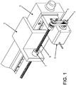
- FIG. 1 shows an exemplary single carriage assembly for an impedance tuner.
- the carriage assembly (2) is mechanically coupled to the impedance tuner (1).
- the carriage assembly (2) is driven by a motor (3), which rotates a timing pulley (4), timing belt (5) and transfers rotation to the lead screw (6).
- a stationary lead screw nut (7) is attached to the carriage unit (2) which allows for forward/reverse movement of the carriage unit (2) when the lead screw (6) is rotated.
- the carriages are mounted on guide rails (not shown in FIG. 1 ).
- FIG. 2 diagrammatically depicts the addition of one additional carriage unit and drive components for an impedance tuner.
- Fundamental carriage (2A) is driven by leadscrew 6A, similar to the carriage assembly and leadscrew shown in FIG. 1
- harmonic carriage (2B) is an additional carriage unit driven by leadscrew 6B.
- This two-carriage unit can move each carriage independently along the tuner transmission line, and is used to set independent impedance points at the fundamental and harmonic frequency simultaneously.
- Driving the harmonic carriage (2B) will require separate drive components to move the harmonic carriage assembly (2B) to a different position from the fundamental carriage (2A) position.
- FIG. 2 shows a dual unit carriage assembly with two sets of drive components. Each item that drives the carriage has its own error associated with manufacturing or operation. A list of exemplary potential errors is set out below.
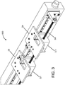
- FIG. 3 shows an exemplary embodiment of a dual unit carriage assembly 100 of an impedance tuner, using the same, i.e. a single, lead screw (6A) with multiple carriage units (2A, 2B).
- a single, lead screw (6A) with multiple carriage units (2A, 2B).
- the reduction of parts improves synchronization between the fundamental carriage and the harmonic carriage.
- motors are employed that each incorporates a lead screw nut into its rotor. This diminishes the parts needed to add multiple carriages onto the drive components of the fundamental frequency, although in another exemplary embodiment, the motor could drive a separate gear or belt drive to turn an external lead screw nut.
- the fundamental carriage (2A) is driven by a motor (3-1) with a built in lead screw nut.
- the motor's rotor now rotates the housed nut while the lead screw (6A) is stationary.
- a second carriage assembly (2B) can be added.
- the second carriage assembly is driven by its own separate motor (5-1) with built in lead screw nut but uses the same stationary lead screw (6A).
- the drive of the harmonic carriage does not affect the drive of the fundamental carriage and thus independent operation can occur.
- each of the movable carriages includes a motor coupled to the single lead screw by a corresponding lead screw nut and configured to apply rotary force to the lead screw nut to turn the nut on the leadscrew and translate the rotary force into linear movement of the nut and carriage along the single lead screw.
- FIG 3 employs two carriages connected to the single lead screw, but the invention is not limited to only two carriages. Any number of carriages may be connected to the same lead screw, and each carriage can move independently from all other carriages connected to the same lead screw.
- the independent motion can be simultaneous independent motion.
- the motors employed in the embodiment 100 of FIG. 3 will typically be controlled by an impedance tuner controller, which may generate control or drive signals to drive the carriage motors as well as any probe motors mounted to the carriage to position impedance probes in directions transverse to the impedance tuner transmission line axis.
- an impedance tuner controller may generate control or drive signals to drive the carriage motors as well as any probe motors mounted to the carriage to position impedance probes in directions transverse to the impedance tuner transmission line axis.
- Exemplary impedance tuners with electronic controllers, application software, drivers, motors and carriages are described, for example, in US 2012/0049970 , entitled Systems and Methods for Impedance Tuner Initialization, the '970 publication.
- the multiple carriages in FIG. 3 can carry the probes of an impedance tuner, which will move along the transmission line with each carriage, and typically each carriage can also carry motors to move the probes transverse to the transmission line as well.
- FIGS. 4A and 4B show an embodiment of two carriage motors (3-1 and 5-1) (carriage components have been hidden for clarity) on one lead screw (6A).
- Diagrammatic cross sectional views FIGS. 4B , 5 , and 6 ) shows the use of a lead screw nut (3-1A; 5-1A) mounted inside and driven by the motor's rotor to achieve motion.
- the nut is integrated with the rotor, in this example, as it spins with the rotor.
- the variance in position between the fundamental carriage (3-1) and harmonic carriage (5-1) is the sum of variance in lead screw errors. Additional errors, such as tolerances in the timing belt pulley, belt, and bearings are removed. Motors with internal lead screw nuts are commercially available.
- FIG. 2A of the '970 publication shows an exemplary impedance tuner 50, and a corresponding diagram is set out herein as FIG. 7A .
- FIG. 2B of the '970 publication shows a schematic diagram of an exemplary controller/computer which controls operation of an impedance tuner such as tuner 50, and a corresponding schematic diagram is set out herein as FIG. 7B .
- FIG. 7A illustrates an exemplary embodiment of a two-carriage impedance tuner 50, with carriages 60 and 70.
- the tuner 50 includes a pair of opposed or end walls 52 and 54 on which the center conductor 10 is supported by dielectric bushings (not shown). The end walls are mounted to a bottom plate 55.
- the opposed conductive ground planes 12, 14 are supported between the end walls, so that the RF transmission line in this example is a slabline which includes the center conductor and the opposed conductive ground planes.
- RF connectors 56, 58 are provided for making electrical connection to the center conductor on opposed sides of the tuner. Connector 56 is typically connected or coupled to a device under test (DUT).
- DUT device under test
- probe carriages 60 and 70 are mounted for movement along an axis parallel to the center conductor 10. Typically the carriages are mounted on guide rails (not shown in FIG. 7A ).
- FIG. 7B illustrates a control system 200 including a controller/computer 202, programmed with application software and tuner driver software, and sensors 240 including limit sensors. While FIG. 7B illustrates an example of a tuner control system for a two carriage system (carriage 1 and carriage 2) with two probes per carriage, the system may be used with a tuner with more than two carriages, with one or multiple probes per carriage. In the example shown in FIG.
- the sensors 240 include position sensors connected through the interface circuit 210 to the controller/computer, and also optionally to some or all of the motors 220A, 220B, 220C, 230A, 230B, 230C, and also to some or all of the motor control circuits 222A, 222B, 222C, 232A, 232B, 232C.
- the carriage 1 and 2 motors 220A, 230A are configured to move the carriages 1 and 2 parallel to the transmission line.
- Each carriage may include two probes and probe motors 220B, 220C, 230B, 230C, which are configured to move the respective probes in directions transverse to the transmission line.
- the motors may be stepper motors, although other motor types, such as DC motors, may be employed.
- FIG. 8 illustrates diagrammatically an exemplary multiple carriage drive system, employing respective carriage-mounted motors 3-1' and 5-1' whose rotor shafts 3-1B' and 5-1B' drive the leadscrew nuts 3-1A' and 5-1A' through respective belts 3-1C' and 5-1C'.
- a suitable support system (not shown) connects the leadscrew nuts to the respective carriage, so that the motion of the nuts on the stationary leadscrew 6A results in independent motion of the respective carriages.
Landscapes
- Engineering & Computer Science (AREA)
- General Engineering & Computer Science (AREA)
- Physics & Mathematics (AREA)
- General Physics & Mathematics (AREA)
- Mechanical Engineering (AREA)
- Transmission Devices (AREA)
Claims (15)
- Ein Impedanztuner mit einer RF-Übertragungsleitung ist gekennzeichnet dadurch, dass der Impedanztuner aus Folgendem besteht:einer einzelnen Leitspindel (6A);einer Vielzahl an beweglichen Maschinenschlitten (2A, 2B), die mit der genannten einzelnen Leitspindel (6A) verbunden sind, wobei jeder der Maschinenschlitten (2A, 2B), der mit der einzelnen Leitspindel (6A) verbunden ist, für eine unabhängige Bewegung in Bezug auf die anderen Maschinenschlitten (2A, 2B) eingestellt ist, um die Maschinenschlitten (2A, 2B) entlang einer Achse, die parallel zur RF-Übergangsleitung läuft, zu bewegen;einem motorisierten Antriebssystem zur unabhängigen Bewegung der Vielzahl an Maschinenschlitten (2A, 2B) entlang der einzelnen Leitspindel (6A).
- Beim Impedanztuner der Reklamation 1 ist die Vielzahl der Maschinenschlitten (2A, 2B), die mit der einzelnen Leitspindel (6A) verbunden sind, zwei Maschinenschlitten.
- Beim Impedanztuner der Reklamation 1 ist die Vielzahl der Maschinenschlitten (2A, 2B), die mit der einzelnen Leitspindel (6A) verbunden sind, mehr als zwei Maschinenschlitten.
- Beim Impedanztuner der Reklamation 1 dreht sich die Leitspindel (6A) nicht, und das motorisierte Antriebssystem für jede der Vielzahl an Maschinenschlitten (2A, 2B) besteht aus einem Motor (3-1, 5-1) am Maschinenschlitten, der eine Mutter (3-1A, 5-1A) an der Leitspindel (6A) dreht.
- Beim Impedanztuner der Reklamation 4 befindet sich die Leitspindelmutter (3-1A, 5-1A) der Leitspindel (6A) bei mindestens einem der Maschinenschlitten (2A, 2B) im Maschinenschlittenmotor (3-1, 5-1).
- Beim Impedanztuner der Reklamation 4 befindet sich die Leitspindelmutter (3-1A', 5-1A') der Leitspindel (6A) bei mindestens einem der Maschinenschlitten (2A, 2B) außerhalb des Maschinenschlittenmotors (3-1', 5-1').
- Der Impedanztuner der Reklamation 1 besteht weiterhin aus:
einer Steuerung (202), die mit dem motorisierten Antriebssystem verkoppelt ist und so eingestellt ist, dass sie Antriebsbefehle gibt, um den Betrieb des motorisierten Antriebssystems zu steuern. - Der Impedanztuner aller vorherigen Reklamationen, bei denen:die einzelne Leitspindel sich nicht dreht (6A); undjede der Vielfalt an beweglichen Maschinenschlitten (2A, 2B) einen Maschinenmotor (3-1, 5-1) hat, der mit der genannten einzelnen Leitspindel (6A) über eine dazugehörige Leitspindelmutter (3-1A, 5-1A) verkoppelt ist und so eingestellt ist, dass er eine Drehkraft an der Leitspindelmutter (3-1A, 5-1A) anwendet, um die Mutter (3-1A, 5-1A) an der Leitspindel (6A) zu drehen und die Drehkraft in eine Linearbewegung der Mutter und des Maschinenschlittens (2A, 2B) entlang der einzelnen Leitspindel (6A) umzuwandeln.
- Beim Impedanztuner der Reklamation 8 befindet sich die Leitspindelmutter (3-1A, 5-1A) der einzelnen Leitspindel (6A) bei mindestens einem der Maschinenschlitten (2A, 2B) im Maschinenschlittenmotor (3-1, 5-1).
- Beim Impedanztuner der Reklamation 8 befindet sich die Leitspindelmutter (3-1A, 5-1A) der Leitspindel (6A) bei mindestens einem der Maschinenschlitten (3-1, 5-1) außerhalb des Maschinenschlittenmotors (3-1, 5-1).
- Beim Impedanztuner der Reklamation 8 ist die Vielzahl der Maschinenschlitten (2A, 2B), die mit der einzelnen Leitspindel (6A) verbunden sind, zwei Maschinenschlitten (2A, 2B).
- Beim Impedanztuner der Reklamation 8 ist die Vielzahl der Maschinenschlitten (2A, 2B), die mit der einzelnen Leitspindel (6A) verbunden sind, mehr als zwei Maschinenschlitten.
- Der Impedanztuner der Reklamation 8 besteht weiterhin aus:
einer Steuerung (202), die mit dem motorisierten Antriebssystem verkoppelt ist und so eingestellt ist, dass sie Antriebsbefehle gibt, um den Betrieb des motorisierten Antriebssystems zu steuern. - Der Impedanztuner der Reklamation 1 oder Reklamation 8 besteht weiterhin aus mindestens einer Sonde, die von jeder der Vielzahl an Maschinenschlitten (2A, 2B) getragen wird und so eingestellt ist, dass sie sich diagonal zur RF-Übergangsleitung bewegt.
- Beim Impedanztuner der Reklamation 1 oder Reklamation 8 ist die RF-Übergangsleitung eine Flachleitung, die aus einer zentralen Leitung zwischen entgegengesetzten Grundplattenstrukturen besteht.
Applications Claiming Priority (3)
| Application Number | Priority Date | Filing Date | Title |
|---|---|---|---|
| US201462006708P | 2014-06-02 | 2014-06-02 | |
| US14/724,079 US9148127B1 (en) | 2014-06-02 | 2015-05-28 | Multi-carriage impedance tuner with single lead screw |
| PCT/US2015/033250 WO2015187492A1 (en) | 2014-06-02 | 2015-05-29 | Multi-carriage impedance tuner with single lead screw |
Publications (2)
| Publication Number | Publication Date |
|---|---|
| EP3149495A1 EP3149495A1 (de) | 2017-04-05 |
| EP3149495B1 true EP3149495B1 (de) | 2018-11-21 |
Family
ID=54149714
Family Applications (1)
| Application Number | Title | Priority Date | Filing Date |
|---|---|---|---|
| EP15736688.1A Active EP3149495B1 (de) | 2014-06-02 | 2015-05-29 | Mehrträgerimpedanztuner mit einer einzigen leitspindel |
Country Status (5)
| Country | Link |
|---|---|
| US (1) | US9148127B1 (de) |
| EP (1) | EP3149495B1 (de) |
| CN (1) | CN106416064B (de) |
| CA (1) | CA2973340C (de) |
| WO (1) | WO2015187492A1 (de) |
Families Citing this family (8)
| Publication number | Priority date | Publication date | Assignee | Title |
|---|---|---|---|---|
| US10101363B2 (en) * | 2015-04-12 | 2018-10-16 | Keysight Technologies, Inc. | Coaxial connector locking bracket |
| US10187228B1 (en) * | 2017-05-24 | 2019-01-22 | Christos Tsironis | Integrated split signal hybrid harmonic tuner |
| US10560067B2 (en) * | 2018-01-17 | 2020-02-11 | Maury Microwave, Inc. | Broadband probes for impedance tuners |
| US11879920B1 (en) * | 2020-07-14 | 2024-01-23 | Christos Tsironis | High power dual probe tuner and method |
| US11460530B1 (en) * | 2020-08-14 | 2022-10-04 | Christos Tsironis | Slide screw tuner with adjustable pitch |
| US12347916B1 (en) * | 2022-10-14 | 2025-07-01 | Christos Tsironis | Waveguide slide screw tuner and method |
| US12519458B1 (en) * | 2023-11-30 | 2026-01-06 | Christos Tsironis | Low frequency load pull tuner using dielectric filled spiral airline |
| CN118408009B (zh) * | 2024-07-01 | 2024-10-01 | 苏州云雀机器人科技有限公司 | 一种中空旋转直线传动滑台 |
Family Cites Families (6)
| Publication number | Priority date | Publication date | Assignee | Title |
|---|---|---|---|---|
| FR2142576B1 (de) * | 1971-06-21 | 1975-09-26 | Snecma | |
| US7034629B2 (en) * | 2001-12-31 | 2006-04-25 | Christos Tsironis | High frequency, high reflection pre-matching tuners with variable zero initialization |
| US6850076B2 (en) * | 2002-12-23 | 2005-02-01 | Christos Tsironis | Microwave tuners for wideband high reflection applications |
| US7135941B1 (en) * | 2004-05-24 | 2006-11-14 | Christos Tsironis | Triple probe automatic slide screw load pull tuner and method |
| US8907750B2 (en) * | 2010-08-25 | 2014-12-09 | Maury Microwave, Inc. | Systems and methods for impedance tuner initialization |
| CN202583335U (zh) * | 2011-09-28 | 2012-12-05 | 茂瑞微波测量设备有限公司 | 阻抗调谐器 |
-
2015
- 2015-05-28 US US14/724,079 patent/US9148127B1/en active Active
- 2015-05-29 EP EP15736688.1A patent/EP3149495B1/de active Active
- 2015-05-29 CN CN201580028369.6A patent/CN106416064B/zh active Active
- 2015-05-29 CA CA2973340A patent/CA2973340C/en active Active
- 2015-05-29 WO PCT/US2015/033250 patent/WO2015187492A1/en not_active Ceased
Non-Patent Citations (1)
| Title |
|---|
| None * |
Also Published As
| Publication number | Publication date |
|---|---|
| CN106416064B (zh) | 2018-10-23 |
| EP3149495A1 (de) | 2017-04-05 |
| CA2973340A1 (en) | 2015-12-10 |
| WO2015187492A1 (en) | 2015-12-10 |
| CN106416064A (zh) | 2017-02-15 |
| US9148127B1 (en) | 2015-09-29 |
| CA2973340C (en) | 2019-09-03 |
Similar Documents
| Publication | Publication Date | Title |
|---|---|---|
| CA2973340C (en) | Multi-carriage impedance tuner with single lead screw | |
| US8907750B2 (en) | Systems and methods for impedance tuner initialization | |
| US10429484B1 (en) | Compact harmonic tuner system with rotating probes | |
| US10700402B1 (en) | Compact millimeter-wave tuner | |
| US11885773B2 (en) | Methods and apparatus to perform load measurements on flexible substrates | |
| KR102043453B1 (ko) | 수동 변환형 굽힘 신뢰성 검사 장치 | |
| CN104266838A (zh) | 电磁转差离合器性能试验台 | |
| RU2645426C2 (ru) | Устройство для механических испытаний малой шестерни между внутренним зубчатым венцом и внешним зубчатым венцом и(или) между двумя внешними зубчатыми венцами при регулируемом угле | |
| US9602072B1 (en) | Compact impedance tuner | |
| US9647629B1 (en) | Variable capacitors for high accuracy tuning | |
| EP3028339B1 (de) | Ultrabreitbandiger impedanztuner | |
| CA2973351C (en) | Impedance tuners with position feedback | |
| JP5123753B2 (ja) | 基板固定装置および基板検査装置 | |
| TW201518725A (zh) | 壓力測試機 | |
| US11428771B1 (en) | Low profile high speed load pull tuner system | |
| US6581486B1 (en) | Integrated circuit tester having a fail-safe mechanism for moving IC-chips | |
| CN218885383U (zh) | 内窥镜的疲劳测试机构及疲劳测试设备 | |
| US12259409B1 (en) | Harmonic load pull tuner | |
| CN107703474B (zh) | 一种电器产品检测装置及控制方法 | |
| KR102156245B1 (ko) | 검사용 회전스테이지 | |
| Lei et al. | A Monobit Built-In Test and Diagnostic System for Flexible Electronic Interconnect | |
| CN102818580B (zh) | 一种非接触式传感器位置检测仪及其检测方法 | |
| Brouillette | A shaft multiplication precision angle encoder |
Legal Events
| Date | Code | Title | Description |
|---|---|---|---|
| STAA | Information on the status of an ep patent application or granted ep patent |
Free format text: STATUS: THE INTERNATIONAL PUBLICATION HAS BEEN MADE |
|
| PUAI | Public reference made under article 153(3) epc to a published international application that has entered the european phase |
Free format text: ORIGINAL CODE: 0009012 |
|
| STAA | Information on the status of an ep patent application or granted ep patent |
Free format text: STATUS: REQUEST FOR EXAMINATION WAS MADE |
|
| 17P | Request for examination filed |
Effective date: 20161221 |
|
| AK | Designated contracting states |
Kind code of ref document: A1 Designated state(s): AL AT BE BG CH CY CZ DE DK EE ES FI FR GB GR HR HU IE IS IT LI LT LU LV MC MK MT NL NO PL PT RO RS SE SI SK SM TR |
|
| AX | Request for extension of the european patent |
Extension state: BA ME |
|
| DAV | Request for validation of the european patent (deleted) | ||
| DAX | Request for extension of the european patent (deleted) | ||
| REG | Reference to a national code |
Ref country code: DE Ref legal event code: R079 Ref document number: 602015020019 Country of ref document: DE Free format text: PREVIOUS MAIN CLASS: G01R0001067000 Ipc: H03J0001060000 |
|
| RIC1 | Information provided on ipc code assigned before grant |
Ipc: G01R 1/067 20060101ALI20180425BHEP Ipc: F16H 25/20 20060101ALI20180425BHEP Ipc: H01P 5/04 20060101ALI20180425BHEP Ipc: H03J 1/06 20060101AFI20180425BHEP Ipc: G01R 27/28 20060101ALI20180425BHEP |
|
| GRAP | Despatch of communication of intention to grant a patent |
Free format text: ORIGINAL CODE: EPIDOSNIGR1 |
|
| STAA | Information on the status of an ep patent application or granted ep patent |
Free format text: STATUS: GRANT OF PATENT IS INTENDED |
|
| INTG | Intention to grant announced |
Effective date: 20180601 |
|
| GRAS | Grant fee paid |
Free format text: ORIGINAL CODE: EPIDOSNIGR3 |
|
| GRAA | (expected) grant |
Free format text: ORIGINAL CODE: 0009210 |
|
| STAA | Information on the status of an ep patent application or granted ep patent |
Free format text: STATUS: THE PATENT HAS BEEN GRANTED |
|
| AK | Designated contracting states |
Kind code of ref document: B1 Designated state(s): AL AT BE BG CH CY CZ DE DK EE ES FI FR GB GR HR HU IE IS IT LI LT LU LV MC MK MT NL NO PL PT RO RS SE SI SK SM TR |
|
| REG | Reference to a national code |
Ref country code: CH Ref legal event code: EP |
|
| REG | Reference to a national code |
Ref country code: IE Ref legal event code: FG4D |
|
| REG | Reference to a national code |
Ref country code: DE Ref legal event code: R096 Ref document number: 602015020019 Country of ref document: DE |
|
| REG | Reference to a national code |
Ref country code: AT Ref legal event code: REF Ref document number: 1068736 Country of ref document: AT Kind code of ref document: T Effective date: 20181215 |
|
| REG | Reference to a national code |
Ref country code: NL Ref legal event code: MP Effective date: 20181121 |
|
| REG | Reference to a national code |
Ref country code: AT Ref legal event code: MK05 Ref document number: 1068736 Country of ref document: AT Kind code of ref document: T Effective date: 20181121 |
|
| PG25 | Lapsed in a contracting state [announced via postgrant information from national office to epo] |
Ref country code: IS Free format text: LAPSE BECAUSE OF FAILURE TO SUBMIT A TRANSLATION OF THE DESCRIPTION OR TO PAY THE FEE WITHIN THE PRESCRIBED TIME-LIMIT Effective date: 20190321 Ref country code: LT Free format text: LAPSE BECAUSE OF FAILURE TO SUBMIT A TRANSLATION OF THE DESCRIPTION OR TO PAY THE FEE WITHIN THE PRESCRIBED TIME-LIMIT Effective date: 20181121 Ref country code: HR Free format text: LAPSE BECAUSE OF FAILURE TO SUBMIT A TRANSLATION OF THE DESCRIPTION OR TO PAY THE FEE WITHIN THE PRESCRIBED TIME-LIMIT Effective date: 20181121 Ref country code: NO Free format text: LAPSE BECAUSE OF FAILURE TO SUBMIT A TRANSLATION OF THE DESCRIPTION OR TO PAY THE FEE WITHIN THE PRESCRIBED TIME-LIMIT Effective date: 20190221 Ref country code: BG Free format text: LAPSE BECAUSE OF FAILURE TO SUBMIT A TRANSLATION OF THE DESCRIPTION OR TO PAY THE FEE WITHIN THE PRESCRIBED TIME-LIMIT Effective date: 20190221 Ref country code: ES Free format text: LAPSE BECAUSE OF FAILURE TO SUBMIT A TRANSLATION OF THE DESCRIPTION OR TO PAY THE FEE WITHIN THE PRESCRIBED TIME-LIMIT Effective date: 20181121 Ref country code: LV Free format text: LAPSE BECAUSE OF FAILURE TO SUBMIT A TRANSLATION OF THE DESCRIPTION OR TO PAY THE FEE WITHIN THE PRESCRIBED TIME-LIMIT Effective date: 20181121 Ref country code: AT Free format text: LAPSE BECAUSE OF FAILURE TO SUBMIT A TRANSLATION OF THE DESCRIPTION OR TO PAY THE FEE WITHIN THE PRESCRIBED TIME-LIMIT Effective date: 20181121 Ref country code: FI Free format text: LAPSE BECAUSE OF FAILURE TO SUBMIT A TRANSLATION OF THE DESCRIPTION OR TO PAY THE FEE WITHIN THE PRESCRIBED TIME-LIMIT Effective date: 20181121 |
|
| PG25 | Lapsed in a contracting state [announced via postgrant information from national office to epo] |
Ref country code: PT Free format text: LAPSE BECAUSE OF FAILURE TO SUBMIT A TRANSLATION OF THE DESCRIPTION OR TO PAY THE FEE WITHIN THE PRESCRIBED TIME-LIMIT Effective date: 20190321 Ref country code: SE Free format text: LAPSE BECAUSE OF FAILURE TO SUBMIT A TRANSLATION OF THE DESCRIPTION OR TO PAY THE FEE WITHIN THE PRESCRIBED TIME-LIMIT Effective date: 20181121 Ref country code: AL Free format text: LAPSE BECAUSE OF FAILURE TO SUBMIT A TRANSLATION OF THE DESCRIPTION OR TO PAY THE FEE WITHIN THE PRESCRIBED TIME-LIMIT Effective date: 20181121 Ref country code: RS Free format text: LAPSE BECAUSE OF FAILURE TO SUBMIT A TRANSLATION OF THE DESCRIPTION OR TO PAY THE FEE WITHIN THE PRESCRIBED TIME-LIMIT Effective date: 20181121 Ref country code: GR Free format text: LAPSE BECAUSE OF FAILURE TO SUBMIT A TRANSLATION OF THE DESCRIPTION OR TO PAY THE FEE WITHIN THE PRESCRIBED TIME-LIMIT Effective date: 20190222 Ref country code: NL Free format text: LAPSE BECAUSE OF FAILURE TO SUBMIT A TRANSLATION OF THE DESCRIPTION OR TO PAY THE FEE WITHIN THE PRESCRIBED TIME-LIMIT Effective date: 20181121 |
|
| PG25 | Lapsed in a contracting state [announced via postgrant information from national office to epo] |
Ref country code: IT Free format text: LAPSE BECAUSE OF FAILURE TO SUBMIT A TRANSLATION OF THE DESCRIPTION OR TO PAY THE FEE WITHIN THE PRESCRIBED TIME-LIMIT Effective date: 20181121 Ref country code: DK Free format text: LAPSE BECAUSE OF FAILURE TO SUBMIT A TRANSLATION OF THE DESCRIPTION OR TO PAY THE FEE WITHIN THE PRESCRIBED TIME-LIMIT Effective date: 20181121 Ref country code: PL Free format text: LAPSE BECAUSE OF FAILURE TO SUBMIT A TRANSLATION OF THE DESCRIPTION OR TO PAY THE FEE WITHIN THE PRESCRIBED TIME-LIMIT Effective date: 20181121 Ref country code: CZ Free format text: LAPSE BECAUSE OF FAILURE TO SUBMIT A TRANSLATION OF THE DESCRIPTION OR TO PAY THE FEE WITHIN THE PRESCRIBED TIME-LIMIT Effective date: 20181121 |
|
| REG | Reference to a national code |
Ref country code: DE Ref legal event code: R097 Ref document number: 602015020019 Country of ref document: DE |
|
| PG25 | Lapsed in a contracting state [announced via postgrant information from national office to epo] |
Ref country code: RO Free format text: LAPSE BECAUSE OF FAILURE TO SUBMIT A TRANSLATION OF THE DESCRIPTION OR TO PAY THE FEE WITHIN THE PRESCRIBED TIME-LIMIT Effective date: 20181121 Ref country code: SK Free format text: LAPSE BECAUSE OF FAILURE TO SUBMIT A TRANSLATION OF THE DESCRIPTION OR TO PAY THE FEE WITHIN THE PRESCRIBED TIME-LIMIT Effective date: 20181121 Ref country code: EE Free format text: LAPSE BECAUSE OF FAILURE TO SUBMIT A TRANSLATION OF THE DESCRIPTION OR TO PAY THE FEE WITHIN THE PRESCRIBED TIME-LIMIT Effective date: 20181121 Ref country code: SM Free format text: LAPSE BECAUSE OF FAILURE TO SUBMIT A TRANSLATION OF THE DESCRIPTION OR TO PAY THE FEE WITHIN THE PRESCRIBED TIME-LIMIT Effective date: 20181121 |
|
| PLBE | No opposition filed within time limit |
Free format text: ORIGINAL CODE: 0009261 |
|
| STAA | Information on the status of an ep patent application or granted ep patent |
Free format text: STATUS: NO OPPOSITION FILED WITHIN TIME LIMIT |
|
| 26N | No opposition filed |
Effective date: 20190822 |
|
| PG25 | Lapsed in a contracting state [announced via postgrant information from national office to epo] |
Ref country code: SI Free format text: LAPSE BECAUSE OF FAILURE TO SUBMIT A TRANSLATION OF THE DESCRIPTION OR TO PAY THE FEE WITHIN THE PRESCRIBED TIME-LIMIT Effective date: 20181121 |
|
| REG | Reference to a national code |
Ref country code: DE Ref legal event code: R119 Ref document number: 602015020019 Country of ref document: DE |
|
| REG | Reference to a national code |
Ref country code: CH Ref legal event code: PL |
|
| PG25 | Lapsed in a contracting state [announced via postgrant information from national office to epo] |
Ref country code: CH Free format text: LAPSE BECAUSE OF NON-PAYMENT OF DUE FEES Effective date: 20190531 Ref country code: LI Free format text: LAPSE BECAUSE OF NON-PAYMENT OF DUE FEES Effective date: 20190531 Ref country code: MC Free format text: LAPSE BECAUSE OF FAILURE TO SUBMIT A TRANSLATION OF THE DESCRIPTION OR TO PAY THE FEE WITHIN THE PRESCRIBED TIME-LIMIT Effective date: 20181121 |
|
| REG | Reference to a national code |
Ref country code: BE Ref legal event code: MM Effective date: 20190531 |
|
| PG25 | Lapsed in a contracting state [announced via postgrant information from national office to epo] |
Ref country code: LU Free format text: LAPSE BECAUSE OF NON-PAYMENT OF DUE FEES Effective date: 20190529 |
|
| PG25 | Lapsed in a contracting state [announced via postgrant information from national office to epo] |
Ref country code: TR Free format text: LAPSE BECAUSE OF FAILURE TO SUBMIT A TRANSLATION OF THE DESCRIPTION OR TO PAY THE FEE WITHIN THE PRESCRIBED TIME-LIMIT Effective date: 20181121 |
|
| PG25 | Lapsed in a contracting state [announced via postgrant information from national office to epo] |
Ref country code: DE Free format text: LAPSE BECAUSE OF NON-PAYMENT OF DUE FEES Effective date: 20191203 Ref country code: IE Free format text: LAPSE BECAUSE OF NON-PAYMENT OF DUE FEES Effective date: 20190529 |
|
| PG25 | Lapsed in a contracting state [announced via postgrant information from national office to epo] |
Ref country code: BE Free format text: LAPSE BECAUSE OF NON-PAYMENT OF DUE FEES Effective date: 20190531 |
|
| PG25 | Lapsed in a contracting state [announced via postgrant information from national office to epo] |
Ref country code: CY Free format text: LAPSE BECAUSE OF FAILURE TO SUBMIT A TRANSLATION OF THE DESCRIPTION OR TO PAY THE FEE WITHIN THE PRESCRIBED TIME-LIMIT Effective date: 20181121 |
|
| PG25 | Lapsed in a contracting state [announced via postgrant information from national office to epo] |
Ref country code: MT Free format text: LAPSE BECAUSE OF FAILURE TO SUBMIT A TRANSLATION OF THE DESCRIPTION OR TO PAY THE FEE WITHIN THE PRESCRIBED TIME-LIMIT Effective date: 20181121 Ref country code: HU Free format text: LAPSE BECAUSE OF FAILURE TO SUBMIT A TRANSLATION OF THE DESCRIPTION OR TO PAY THE FEE WITHIN THE PRESCRIBED TIME-LIMIT; INVALID AB INITIO Effective date: 20150529 |
|
| PG25 | Lapsed in a contracting state [announced via postgrant information from national office to epo] |
Ref country code: MK Free format text: LAPSE BECAUSE OF FAILURE TO SUBMIT A TRANSLATION OF THE DESCRIPTION OR TO PAY THE FEE WITHIN THE PRESCRIBED TIME-LIMIT Effective date: 20181121 |
|
| P01 | Opt-out of the competence of the unified patent court (upc) registered |
Effective date: 20230426 |
|
| PGFP | Annual fee paid to national office [announced via postgrant information from national office to epo] |
Ref country code: GB Payment date: 20250423 Year of fee payment: 11 |
|
| PGFP | Annual fee paid to national office [announced via postgrant information from national office to epo] |
Ref country code: FR Payment date: 20250423 Year of fee payment: 11 |