EP3149443B1 - Diagnose von antriebswellenscheibenkupplungen - Google Patents
Diagnose von antriebswellenscheibenkupplungen Download PDFInfo
- Publication number
- EP3149443B1 EP3149443B1 EP15803192.2A EP15803192A EP3149443B1 EP 3149443 B1 EP3149443 B1 EP 3149443B1 EP 15803192 A EP15803192 A EP 15803192A EP 3149443 B1 EP3149443 B1 EP 3149443B1
- Authority
- EP
- European Patent Office
- Prior art keywords
- data
- drive shaft
- processing
- aircraft
- domain signal
- Prior art date
- Legal status (The legal status is an assumption and is not a legal conclusion. Google has not performed a legal analysis and makes no representation as to the accuracy of the status listed.)
- Active
Links
- 230000008878 coupling Effects 0.000 title claims description 27
- 238000010168 coupling process Methods 0.000 title claims description 27
- 238000005859 coupling reaction Methods 0.000 title claims description 27
- 238000003745 diagnosis Methods 0.000 title 1
- 238000000034 method Methods 0.000 claims description 28
- 230000036541 health Effects 0.000 claims description 15
- 238000012423 maintenance Methods 0.000 claims description 15
- 238000012545 processing Methods 0.000 claims description 13
- 238000007689 inspection Methods 0.000 claims description 12
- 238000005070 sampling Methods 0.000 claims description 10
- 230000036316 preload Effects 0.000 claims description 9
- 238000005336 cracking Methods 0.000 claims description 8
- 238000005259 measurement Methods 0.000 claims description 8
- 230000000694 effects Effects 0.000 claims description 6
- 238000001514 detection method Methods 0.000 claims description 5
- 238000003475 lamination Methods 0.000 claims description 5
- 230000008569 process Effects 0.000 claims description 5
- 238000005260 corrosion Methods 0.000 claims description 4
- 230000007797 corrosion Effects 0.000 claims description 4
- 238000012935 Averaging Methods 0.000 claims description 3
- 238000012952 Resampling Methods 0.000 claims 2
- 238000004458 analytical method Methods 0.000 description 15
- 230000006870 function Effects 0.000 description 4
- 238000012544 monitoring process Methods 0.000 description 4
- 230000000712 assembly Effects 0.000 description 2
- 238000000429 assembly Methods 0.000 description 2
- 230000005540 biological transmission Effects 0.000 description 2
- 230000002596 correlated effect Effects 0.000 description 2
- 238000013499 data model Methods 0.000 description 2
- 238000010586 diagram Methods 0.000 description 2
- 238000005516 engineering process Methods 0.000 description 2
- RZVHIXYEVGDQDX-UHFFFAOYSA-N 9,10-anthraquinone Chemical compound C1=CC=C2C(=O)C3=CC=CC=C3C(=O)C2=C1 RZVHIXYEVGDQDX-UHFFFAOYSA-N 0.000 description 1
- 230000001133 acceleration Effects 0.000 description 1
- 238000009825 accumulation Methods 0.000 description 1
- 238000013459 approach Methods 0.000 description 1
- 238000005452 bending Methods 0.000 description 1
- 230000008901 benefit Effects 0.000 description 1
- 238000004364 calculation method Methods 0.000 description 1
- 230000015556 catabolic process Effects 0.000 description 1
- 230000003750 conditioning effect Effects 0.000 description 1
- 230000000875 corresponding effect Effects 0.000 description 1
- 238000006731 degradation reaction Methods 0.000 description 1
- 230000009977 dual effect Effects 0.000 description 1
- 238000011156 evaluation Methods 0.000 description 1
- 230000003993 interaction Effects 0.000 description 1
- 238000012986 modification Methods 0.000 description 1
- 230000004048 modification Effects 0.000 description 1
- 239000002243 precursor Substances 0.000 description 1
- 238000012552 review Methods 0.000 description 1
- 238000011179 visual inspection Methods 0.000 description 1
Images


Classifications
-
- G—PHYSICS
- G01—MEASURING; TESTING
- G01M—TESTING STATIC OR DYNAMIC BALANCE OF MACHINES OR STRUCTURES; TESTING OF STRUCTURES OR APPARATUS, NOT OTHERWISE PROVIDED FOR
- G01M13/00—Testing of machine parts
- G01M13/02—Gearings; Transmission mechanisms
- G01M13/028—Acoustic or vibration analysis
-
- G—PHYSICS
- G01—MEASURING; TESTING
- G01M—TESTING STATIC OR DYNAMIC BALANCE OF MACHINES OR STRUCTURES; TESTING OF STRUCTURES OR APPARATUS, NOT OTHERWISE PROVIDED FOR
- G01M17/00—Testing of vehicles
-
- G—PHYSICS
- G01—MEASURING; TESTING
- G01M—TESTING STATIC OR DYNAMIC BALANCE OF MACHINES OR STRUCTURES; TESTING OF STRUCTURES OR APPARATUS, NOT OTHERWISE PROVIDED FOR
- G01M13/00—Testing of machine parts
- G01M13/02—Gearings; Transmission mechanisms
Definitions
- Mechanical failure modes typically looked for or examined during these inspections include cracking of a disc coupling, buckling of the disc coupling, bolt-hole elongation (e.g., elongation in flanges), corrosion, damage, security, wear, lamination spread, and loss of bolt preload. It is difficult to detect and quantify the severity (e.g., in terms of likelihood of losing complete torque carrying capacity) of each of these failure modes.
- An embodiment according to claim 1 of the present invention is directed to a method applied to one or more components of a drive shaft of an aircraft, the method comprising: obtaining data based on samples of a vibration signal, processing, by at least one processor, the data to obtain a qualitative and quantitative assessment of a health of the one or more components based on an application of the data to at least one model, and outputting the assessment.
- An embodiment according to claim 7 of the present invention is directed to an apparatus for use in connection with an aircraft, the apparatus comprising: at least one processor, and memory having instructions stored thereon that, when executed by the at least one processor, cause the apparatus to: obtain data based on samples of a vibration signal, process the data to obtain a qualitative and quantitative assessment of a health of one or more components of a drive shaft of the aircraft based on an application of the data to at least one model, and output the assessment.
- EP 2 345 894 A2 discloses vibration based mechanical diagnostics in which algorithms may extract some feature of a component which may be used as a statistic of the components' health.
- a measured condition indicator (CI) corresponding to the analysis of the components' health may be a function of transmission error (TE). Because there exists a relationship between TE and the CI for a component that is faulted, the CI is correlated with power transmitted. In drive train components, power may be proportional to measured torque. The relationship between measured CI and torque may be captured over time. An increase in the correlation of torque with the CI would indicate an increase of TE which indicates the propagation of a fault.
- TE transmission error
- EP 2 431 720 A1 relates to a method of measuring torque acting on a drive shaft and a torque measurement system for implementing said method.
- Vibration sensors are attached to each of said main gearbox and said tail gearbox in order to detect gear mesh vibrations resulting from interaction of said drive shaft with said main gear and said tail gear, said detected gear mesh vibrations being transferred to an evaluation unit for analysis.
- EP 0 889 315 A2 discloses a method which includes the steps of acquiring a signal from an acceleration sensor, calculating the Fourier transform in the frequency domain of the signal to obtain a sequence of samples, acquiring from the sequence of samples a set of samples including samples at the meshing frequency of the gears monitored by the sensor, and samples at the harmonic frequencies of the meshing frequency, calculating the energies associated with the set of samples and the signal, calculating a noise energy parameter correlated to the ratio between the energy of the set of samples and the energy of the signal, comparing the noise energy parameter with at least one predetermined threshold, and generating an alarm signal in the event the noise energy parameter exceeds the threshold value.
- US 2009/216398 A1 discloses a health and usage monitoring system (HUMS) of a vehicle.
- the present invention uses a plurality of wireless sensors configured, when activated by a vibration of the vehicle, to monitor one or more components of the vehicle and to communicate health and/or usage data of the one or more components of the vehicle to a data access point.
- the invention is directed to a method, apparatus and aircraft according to the appended claims.
- An embodiment is directed to an aircraft comprising: a drive shaft comprising a plurality of components, a plurality of sensors configured to measure vibration associated with the aircraft, a control computer configured to: sample measurements from the sensors to obtain data, process the data to obtain a qualitative and quantitative assessment of a health of at least one of the components based on an application of the data to at least one model, and output the assessment.
- Exemplary embodiments of apparatuses, systems, and methods are described for predicting the likelihood of failure modes (e.g., cracking of a disc coupling, disc buckling, bolt-hole elongation (e.g., elongation in flanges), corrosion, damage, security, wear, lamination spread, and loss of bolt preload) in disc-style couplings commonly used in transmission or drive shaft systems.
- vibration analyses and physics-based models may be used to predict the likelihood of the failure modes. Vibration analysis may be used to quantify levels of misalignment, unbalance, and bolt preload loss that exist via calculation of various shaft order features. These predictions may be fed into failure mode specific models, along with torque load measurements, if available.
- Vibration-based diagnostics may provide a condition monitoring capability for detecting various failure mode precursors and drivers, thereby providing a level of "fail safe" detection.
- TDS tail drive shaft
- One approach to reduce the maintenance burden associated with disc coupling inspections is to extend the inspection interval based on the details of actual usage of a particular aircraft or system.
- embodiments of this disclosure use load information, vibration analysis, and physics-based models to predict the likelihood of various mechanical failure modes commonly looked for during inspections.
- Enhanced vibration analysis may be used to quantify the levels of misalignment, unbalance, and bolt pre-load loss that exist. These levels may serve as inputs to models, along with the available drive shaft load measurements or predictions.
- Embodiments of the disclosure use physics-based models for the disc coupling assemblies to provide quantitative information that assist in the enhanced interpretation of the vibration data for the drive shaft as well as provide quantitative information relative to the effect of operating conditions / history on the drivers that are believed to influence bolt-hole elongation for the shaft coupling assemblies.
- Quantitative information may be provided to assist in the potential extension of the inspection interval for the disc couplings with minimal impact on operational risk.
- the technology can be used to diagnose the health of drive shaft couplings other than just helicopter drive shafts.
- FIG. 1A illustrates an exemplary rotary wing aircraft 10.
- the aircraft 10 is shown as having a dual, counter-rotating main rotor system 12, which rotates about a rotating main rotor shaft 14U, and a counter-rotating main rotor shaft 14L, both about an axis of rotation A.
- Other types of configurations may be used in some embodiments, such as a single rotor system 12.
- the aircraft 10 includes an airframe F which supports the main rotor system 12 as well as an optional translational thrust system T which provides translational thrust during high speed forward flight, generally parallel to an aircraft longitudinal axis L.
- a main gearbox G located above the aircraft cabin drives the rotor system 12.
- the translational thrust system T may be driven by the same main gearbox G which drives the rotor system 12.
- the main gearbox G is driven by one or more engines E. As shown, the main gearbox G may be interposed between the engines E, the rotor system 12, and the translational thrust system T.
- FIG. 1A Although a particular counter-rotating, coaxial rotor system aircraft configuration is illustrated in the embodiment of FIG. 1A , other rotor systems and other aircraft types such as tilt-wing and tilt-rotor aircrafts may benefit from the present disclosure.
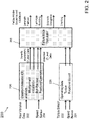
- Computing system 100 may be part of a flight control system of the aircraft 10.
- the system 100 is shown as including a memory 102.
- the memory 102 may store executable instructions.
- the executable instructions may be stored or organized in any manner and at any level of abstraction, such as in connection with one or more applications, processes, routines, procedures, methods, etc. As an example, at least a portion of the instructions are shown in FIG. 1B as being associated with a first program 104a and a second program 104b.
- the instructions stored in the memory 102 may be executed by one or more processors, such as a processor 106.
- the processor 106 may be coupled to one or more input/output (I/O) devices 108.
- the I/O device(s) 108 may include one or more of a keyboard or keypad, a touchscreen or touch panel, a display screen, a microphone, a speaker, a mouse, a button, a remote control, a control stick, a joystick, a printer, a telephone or mobile device (e.g., a smartphone), a sensor, etc.
- the I/O device(s) 108 may be configured to provide an interface to allow a user to interact with the system 100.
- the processor 106 may be coupled to a number 'n' of databases, 110-1, 110-2, ... 110-n.
- the databases 110 may be used to store data, such as data obtained from one or more sensors (e.g., vibration, speed, and torque sensors).
- the data may pertain to one or more parameters associated with a drive shaft of an aircraft (e.g., aircraft 10).
- the system 100 is illustrative. In some embodiments, one or more of the entities may be optional. In some embodiments, additional entities not shown may be included. In some embodiments, the entities may be arranged or organized in a manner different from what is shown in FIG. 1B . For example, in some embodiments, the memory 102 may be coupled to or combined with one or more of the databases 110.
- physics-based modeling may be used to assess the risk of failure due to, e.g., non-corrosion failure modes.
- Embodiments of this disclosure may be used to enhance detectability using existing mechanical diagnostic sensors with an emphasis on the detection and prediction of bolt-hole elongation and cracking and associated drivers.
- a conditioning monitoring capability is provided to detect disc coupling failure modes via vibration data. Any modeling necessary to assess the severity and likelihood of any detected faults may also be provided.
- Raw vibration data 202 and speed sensor data 204 may be provided to a condition indicator (CI) analyses processor, algorithm, or model 206.
- the model 206 may take into consideration one or more factors or modes, such as misalignment, unbalance, bolt pre-load and fractured laminate.
- the model 206 may output one or more levels of data. For example, so-called 3-level data may be used to provide a severity assessment (e.g., healthy, warning, severe). So-called 2-level data may be used for purposes of detection of a boolean condition (e.g., healthy/failed).
- the system 200 may obtain torque data from a torque sensor 222 and speed data from a speed sensor 224 (which may correspond to, or be the same as, the data 204).
- the torque sensor data 222 and/or the speed sensor data 224 may be provided to an operating data model 226, which in turn may pass this data (or a processed or filtered version of it) to a failure mode calculator 266.
- the operating data model 226 may be used to indicate a type of operating mode an aircraft, or the system 200, is in.
- the failure mode calculator 266 may generate one or more outputs indicative of a potential existence of one or more failure modes (e.g., laminate facture, laminate buckling, bolt-hole elongation, cracking, etc.) and associated likelihoods or probabilities thereof. In this manner, the system 200 may provide both quantitative and qualitative characteristics or values.
- one or more failure modes e.g., laminate facture, laminate buckling, bolt-hole elongation, cracking, etc.
- physics-based modeling may be used to translate results of finite element and closed form analyses into models that may be executed in, e.g., near-real time to analyze vibration data (e.g., vibration data 202).
- vibration data e.g., vibration data 202
- Various analyses that may be performed are shown as part of Table 1 below: Analysis Area Method Type of Results How Used Unbalance Closes Form (formulas, equations) Force due to specified unbalance Coupling loads Tolerances Closed Form (formulas, equations) Dolt/Dolt-hole min.
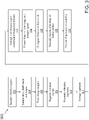
- FIG. 3 a flow chart of a method 300 according to claim 1 of the present invention is shown.
- the method 300 may be executed by one or more systems, components, or devices, such as those described herein (e.g., the system 100 and/or the system 200).
- the method 300 may be used to perform vibration diagnostics or analyses.
- vibration signals may be sampled.
- the sampling may occur periodically or in accordance with a schedule or routine.
- the sampling may occur during system operation.
- drive shaft (rotational) speed and torque may be sampled.
- the data samples of blocks 302 and 304 may be time-stamped to allow them to be compared with each other and compared against other system data.
- the vibration signals may be segmented into multiple segments representing data from one revolution of the shaft based on the nominal shaft speed.
- each of the vibration signal segments may be resampled from constant time based sampling to constant angular based sampling.
- averaging may be performed over one or more of the segments.
- the averaged time domain signals may be converted to the frequency domain.
- various shaft order based features may be extracted from the frequency domain signal.
- the features may correspond to the magnitudes of the frequency domain signal at specified frequencies representing integer multiples of the shaft speed ranging from, e.g., one to forty.
- the extracted features may be compared to thresholds established from data acquired for healthy drive shafts.
- Each feature may be assigned a value based on whether the feature is within expected bounds.
- a value of '0' may correspond to the feature being within a tolerance limit, and may coincide with a nominal or low-level risk.
- a value of '1' may correspond to the feature being outside of a warning limit, and may coincide with moderate risk.
- a value of '2' may correspond to the feature being outside of an alarm limit, and may coincide with severe risk.
- combinations of the extracted features and indications of whether the features exceed the thresholds may be used to quantify the existence and severity of, e.g., unbalance misalignment, loss of bolt preload, coupling cracking, etc.
- diagnostic information may be provided to various models, such as those described herein.
- the models may be used to schedule one or more inspections or maintenance activities.
- the method 300 is illustrative. In some embodiments, one or more of the blocks or operations (or a portion thereof) may be optional. In some embodiments, additional blocks or operations not shown may be included. In some embodiments, the blocks or operations may execute in an order or sequence that is different from what is shown in FIG. 3 .
- embodiments of the disclosure may use operational history, vibration analysis, and physics-based models to detect failure mode drivers and predict the presence of different faults, including bolt-hole elongation and/or cracking, at the end of a specified inspection interval.
- Enhanced vibration analysis may be used to quantify the drivers of coupling degradation. Values of these drivers may serve as a bolt-hole load estimation model; along with the available drive shaft load measurements or predictions.
- finite element models may be used to quantify the stresses induced in the bolt holes, and damage accumulation models may be used to predict the likelihood of the presence of bolt-hole elongation and or cracks.
- embodiments of the disclosure may be used to provide both a condition monitoring capability to detect disc coupling failure modes via vibration data and the modeling necessary to assess the severity and likelihood of any detected faults.
- a maintenance philosophy or program may be altered from scheduled or reactive-based maintenance to maintenance driven by condition-based indicators.
- Aspects of this disclosure may be used to reduce the number or quantity of unanticipated failures, and may be useful in applications where failure is not safety-critical and maintenance is primarily reactive. Safety may be improved while optimizing maintenance and increasing the uptime of an asset (e.g., an aircraft).
- aspects of this disclosure may be geared to, or modified, to account for various types of aircraft and platforms.
- operational or safety requirements may be used to adjust thresholds associated with one or more failure modes.
- aspects of this disclosure may be used in connection with drivetrains.
- aspects of this disclosure may be applied to low speed shafts in a tail section and/or high speed shaft disc couplings.
- various functions or acts may take place at a given location and/or in connection with the operation of one or more apparatuses, systems, or devices. For example, in some embodiments, a portion of a given function or act may be performed at a first device or location, and the remainder of the function or act may be performed at one or more additional devices or locations.
- an apparatus or system may include one or more processors, and memory storing instructions that, when executed by the one or more processors, cause the apparatus or system to perform one or more methodological acts as described herein.
- Various mechanical components known to those of skill in the art may be used in some embodiments.
- Embodiments may be implemented as one or more apparatuses, systems, and/or methods.
- instructions may be stored on one or more computer-readable media, such as a transitory and/or non-transitory computer-readable medium.
- the instructions when executed, may cause an entity (e.g., an apparatus or system) to perform one or more methodological acts as described herein.
Landscapes
- Physics & Mathematics (AREA)
- General Physics & Mathematics (AREA)
- Acoustics & Sound (AREA)
- Testing Of Devices, Machine Parts, Or Other Structures Thereof (AREA)
Claims (13)
- Verfahren, das auf eine oder mehrere Komponenten einer Antriebswelle (14U, 14L) eines Luftfahrzeugs (10) angewendet wird, wobei das Verfahren umfasst:Erhalten von Daten (202) basierend auf Proben eines Schwingungssignals von mindestens einem Sensor, der zum Messen von Schwingungen konfiguriert ist;Verarbeiten der Daten (202) durch mindestens einen Prozessor (106), einschließlich Umwandeln des Schwingungssignals in ein Signal im Frequenzbereich, Extrahieren eines auf der Wellenordnung basierenden Merkmals aus dem Signal im Frequenzbereich und Vergleichen des auf der Wellenordnung basierenden Merkmals, das aus dem Signal im Frequenzbereich extrahiert wurde, mit einem Schwellenwert, der für eine intakte Antriebswelle festgelegt wurde, um eine qualitative und quantitative Bewertung eines Zustands der einen oder mehreren Komponenten der Antriebswelle des Luftfahrzeugs zu erhalten, wobei ein Zustandsindikator auf der Grundlage einer Anwendung der Daten auf mindestens ein physikalisch basiertes Modell erfasst wird, wobei die Verarbeitung der Daten ferner das Abtasten, Zeitstempeln und Segmentieren der Schwingungssignale in eine Vielzahl von Segmenten, die für eine Umdrehung der Antriebswelle (14U, 14L) repräsentativ sind, auf der Grundlage einer Nenndrehzahl der Antriebswelle als Teil der Verarbeitung der Daten (202), das erneute Abtasten der Schwingungssignalsegmente von einer auf konstanter Zeit basierenden Abtastung zu einer auf konstantem Winkel basierenden Abtastung und die Mittelwertbildung der erneut abgetasteten Segmente als Teil der Verarbeitung der Daten (202) einschließt; undAusgeben der Bewertung.
- Verfahren nach Anspruch 1, wobei die erhaltenen Daten (202) auf Abtastungen der Drehzahl und des Drehmoments der Antriebswelle basieren.
- Verfahren nach Anspruch 1, das ferner umfasst:
Umwandeln der gemittelten neu abgetasteten Segmente von einer Signaldarstellung im Zeitbereich in eine Signaldarstellung im Frequenzbereich als Teil der Verarbeitung der Daten (202). - Verfahren nach Anspruch 3, das ferner umfasst:
Extrahieren von Größen aus der Signaldarstellung im Frequenzbereich bei Frequenzen, die ganzzahlige Vielfache einer Drehzahl der Antriebswelle darstellen, als Teil der Verarbeitung der Daten (202). - Verfahren nach Anspruch 4, das ferner umfasst:
Vergleichen der Größen mit Schwellenwerten, die für einen Zustandsindikator festgelegt wurden, der eine intakte Antriebswelle anzeigt; und Planen einer Inspektions- und/oder einer Wartungstätigkeit, wenn der Vergleich anzeigt, dass der Zustandsindikator darauf hinweist, dass die Antriebswelle ungesund ist. - Verfahren nach Anspruch 1, wobei sich der Zustand der einen oder mehreren Komponenten auf einen Zustandsindikator bezieht, der mindestens eines der folgenden Merkmale anzeigt: Rissbildung in der Kupplung, Ausknicken der Scheibe, Dehnung des Bolzenlochs, Korrosion, Beschädigung, Sicherheit, Verschleiß, Ausbreitung der Lamellen und Verlust der Bolzenvorspannung bei scheibenförmigen Kupplungen.
- Vorrichtung (100, 200) zur Verwendung in Verbindung mit einem Luftfahrzeug (10), wobei die Vorrichtung umfasst:mindestens einen Prozessor (106); undSpeicher (102), der Anweisungen speichert, die bei Ausführung durch den mindestens einen Prozessor (106) die Vorrichtung zu Folgendem veranlassen:Erhalten von Daten (202) basierend auf Proben eines Schwingungssignals von mindestens einem Sensor, der zum Messen von Schwingungen konfiguriert ist;Verarbeiten der Daten (202) einschließlich Umwandeln des Schwingungssignals in ein Signal im Frequenzbereich, Extrahieren eines auf der Wellenordnung basierenden Merkmals aus dem Signal im Frequenzbereich und Vergleichen des auf der Wellenordnung basierenden Merkmals, das aus dem Signal im Frequenzbereich extrahiert wurde, mit einem Schwellenwert, der für eine intakte Antriebswelle festgelegt wurde, um eine qualitative und quantitative Bewertung eines Zustands einer oder mehrerer Komponenten einer Antriebswelle (14U, 14L) des Luftfahrzeugs (10) zu erhalten, wobei ein Zustandsindikator auf der Grundlage einer Anwendung der Daten auf mindestens ein physikalisch basiertes Modell erfasst wird, wobei die Verarbeitung der Daten ferner das Abtasten, Zeitstempeln und Segmentieren der Schwingungssignale in eine Vielzahl von Segmenten, die für eine Umdrehung der Antriebswelle (14U, 14L) repräsentativ sind, auf der Grundlage einer Nenndrehzahl der Antriebswelle als Teil der Verarbeitung der Daten (202), das erneute Abtasten der Schwingungssignalsegmente von einer auf konstanter Zeit basierenden Abtastung zu einer auf konstantem Winkel basierenden Abtastung und die Mittelwertbildung der erneut abgetasteten Segmente als Teil der Verarbeitung der Daten (202) einschließt; undAusgeben der Bewertung.
- Vorrichtung nach Anspruch 7, wobei die Anweisungen, wenn sie von dem mindestens einen Prozessor (106) ausgeführt werden, die Vorrichtung zu Folgendem veranlassen:
Umwandeln der gemittelten Segmente von einer Signaldarstellung im Zeitbereich in eine Signaldarstellung im Frequenzbereich als Teil der Verarbeitung der Daten. - Vorrichtung nach Anspruch 8, wobei die Anweisungen, wenn sie von dem mindestens einen Prozessor (106) ausgeführt werden, die Vorrichtung zu Folgendem veranlassen:
Extrahieren von Größen aus der Signaldarstellung im Frequenzbereich bei Frequenzen, die ganzzahlige Vielfache einer Drehzahl der Antriebswelle darstellen, als Teil der Verarbeitung der Daten (202). - Vorrichtung nach Anspruch 9, wobei die Anweisungen, wenn sie von dem mindestens einen Prozessor (106) ausgeführt werden, die Vorrichtung zu Folgendem veranlassen:
Vergleichen der Größen mit Schwellenwerten, die für einen Indikator des Gesundheitszustands festgelegt wurden, der eine intakte Antriebswelle anzeigt und Planen einer Inspektions- und/oder einer Wartungstätigkeit, wenn der Vergleich anzeigt, dass der Indikator des Gesundheitszustands darauf hinweist, dass die Antriebswelle (14U, 14L) ungesund ist. - Luftfahrzeug (10), umfassend:eine Antriebswelle (14U, 14L), die eine Vielzahl an Komponenten umfasst;eine Vielzahl von Sensoren, die dazu konfiguriert sind, Schwingungen (202) zu messen, die dem Luftfahrzeug (14) zugeordnet sind;eine Vorrichtung (100, 200) nach einem der Ansprüche 7 - 10, die dazu konfiguriert ist, Messungen von den Sensoren abzutasten, um die Daten (202) zu erhalten.
- Luftfahrzeug nach Anspruch 11, wobei die Vorrichtung zu Folgendem konfiguriert ist:
Versehen der abgetasteten Messungen mit einem Zeitstempel, wobei die Verarbeitung der Daten (202) auf einem Vergleich von abgetasteten Messungen zu unterschiedlichen Zeiten basierend auf den Zeitstempeln basiert. - Luftfahrzeug nach Anspruch 11, wobei der Zustand der mindestens einen Komponente mindestens eines von Folgendem betrifft: Unwucht, Fehlausrichtung, Verlust der Bolzenvorspannung und Rissbildung in der Kupplung.
Applications Claiming Priority (2)
| Application Number | Priority Date | Filing Date | Title |
|---|---|---|---|
| US201462006473P | 2014-06-02 | 2014-06-02 | |
| PCT/US2015/023526 WO2015187241A1 (en) | 2014-06-02 | 2015-03-31 | Diagnosis of drive shaft disc couplings |
Publications (3)
| Publication Number | Publication Date |
|---|---|
| EP3149443A1 EP3149443A1 (de) | 2017-04-05 |
| EP3149443A4 EP3149443A4 (de) | 2018-02-21 |
| EP3149443B1 true EP3149443B1 (de) | 2022-10-26 |
Family
ID=54767140
Family Applications (1)
| Application Number | Title | Priority Date | Filing Date |
|---|---|---|---|
| EP15803192.2A Active EP3149443B1 (de) | 2014-06-02 | 2015-03-31 | Diagnose von antriebswellenscheibenkupplungen |
Country Status (3)
| Country | Link |
|---|---|
| US (1) | US10190942B2 (de) |
| EP (1) | EP3149443B1 (de) |
| WO (1) | WO2015187241A1 (de) |
Families Citing this family (6)
| Publication number | Priority date | Publication date | Assignee | Title |
|---|---|---|---|---|
| RU2631557C1 (ru) * | 2016-07-27 | 2017-09-25 | Публичное акционерное общество "Казанский вертолетный завод" | Способ определения в полете изгибных напряжений на валу несущего винта вертолета с торсионной втулкой несущего винта |
| US10424134B2 (en) | 2016-08-17 | 2019-09-24 | Bell Helicopter Textron Inc. | Diagnostic method, system and device for a rotorcraft drive system |
| US10380810B2 (en) | 2016-08-17 | 2019-08-13 | Bell Helicopter Textron Inc. | Diagnostic method, system and device for a rotorcraft drive system |
| US10464689B2 (en) | 2016-08-17 | 2019-11-05 | Bell Helicopter Textron Inc. | Diagnostic method, system and device for a rotorcraft drive system |
| US10643405B2 (en) * | 2016-08-17 | 2020-05-05 | Bell Helicopter Textron Inc. | Diagnostic method, system and device for a rotorcraft drive system |
| CN110017957B (zh) * | 2018-01-10 | 2021-08-31 | 国家能源投资集团有限责任公司 | 一种同步分析方法、装置及系统 |
Family Cites Families (14)
| Publication number | Priority date | Publication date | Assignee | Title |
|---|---|---|---|---|
| JPH03279838A (ja) * | 1990-03-28 | 1991-12-11 | Nissan Motor Co Ltd | 部材の破壊発生検出方法 |
| US5381692A (en) * | 1992-12-09 | 1995-01-17 | United Technologies Corporation | Bearing assembly monitoring system |
| IT1293411B1 (it) | 1997-07-04 | 1999-03-01 | Finmeccanica Spa | Metodo di sorveglianza di un gruppo di trasmissione in un veicolo dotato di sensori accelerometrici in base all'energia del segnale, |
| US7321809B2 (en) | 2003-12-30 | 2008-01-22 | The Boeing Company | Methods and systems for analyzing engine unbalance conditions |
| EP1913506A4 (de) | 2005-07-11 | 2008-08-13 | Brooks Automation Inc | Intelligente zustandsüberwachung und fehlerdiagnosesystem für prädiktive wartung |
| US7719416B2 (en) * | 2005-09-09 | 2010-05-18 | Microstrain, Inc. | Energy harvesting, wireless structural health monitoring system |
| US8131420B2 (en) | 2008-02-27 | 2012-03-06 | Simmonds Precision Products, Inc. | Vehicle health and usage monitoring system and method |
| US8288513B2 (en) * | 2008-07-25 | 2012-10-16 | Becton, Dickinson And Company | Defined cell culturing surfaces and methods of use |
| EP2226766A3 (de) * | 2009-03-02 | 2014-06-11 | Sikorsky Aircraft Corporation | Rotorsystem-Gesundheitsüberwachung mit Schaftbelastungsmessungen und virtuelle Überwachung von Lasten |
| EP2502174B1 (de) | 2009-11-16 | 2018-06-13 | Simmonds Precision Products, Inc. | Datenerfassungssystem für bedingungsbasierte pflege |
| US8355879B2 (en) | 2010-01-06 | 2013-01-15 | Simmonds Precision Products, Inc. | Trending of vibration data taking into account torque effect |
| EP2431720B1 (de) | 2010-09-20 | 2013-01-16 | Eurocopter Deutschland GmbH | Verfahren zur Drehmomentmessung und Drehmomentmesssystem für dieses Verfahren |
| US8909453B2 (en) * | 2012-01-12 | 2014-12-09 | Bell-Helicopter Textron Inc. | System and method of measuring and monitoring torque in a rotorcraft drive system |
| US9218693B2 (en) * | 2013-03-15 | 2015-12-22 | Bell Helicopter Textron Inc. | Drive system power measurement and diagnostic system |
-
2015
- 2015-03-31 WO PCT/US2015/023526 patent/WO2015187241A1/en active Application Filing
- 2015-03-31 EP EP15803192.2A patent/EP3149443B1/de active Active
- 2015-03-31 US US15/316,017 patent/US10190942B2/en active Active
Also Published As
| Publication number | Publication date |
|---|---|
| WO2015187241A1 (en) | 2015-12-10 |
| US10190942B2 (en) | 2019-01-29 |
| US20170089805A1 (en) | 2017-03-30 |
| EP3149443A4 (de) | 2018-02-21 |
| EP3149443A1 (de) | 2017-04-05 |
Similar Documents
| Publication | Publication Date | Title |
|---|---|---|
| EP3149443B1 (de) | Diagnose von antriebswellenscheibenkupplungen | |
| RU2388661C2 (ru) | Способ контроля двигателя самолета | |
| US8457836B2 (en) | Systems for announcing the health of aircraft control elements | |
| US20060004499A1 (en) | Structural health management architecture using sensor technology | |
| EP2092401B1 (de) | Detektion harter landungen | |
| US10360737B2 (en) | System and method for improved drive system diagnostics | |
| US20170331844A1 (en) | Systems and methods for assessing airframe health | |
| US10388087B2 (en) | System and method for improved health management and maintenance decision support | |
| US8983712B2 (en) | Method and system for detecting pushrod faults | |
| EP3284670B1 (de) | Diagnoseverfahren, -system und -vorrichtung für ein drehflügelflugzeugantriebssystem | |
| US10677765B2 (en) | Structural health monitoring of cyclically loaded structures | |
| Hassan et al. | Analysis of nonlinear vibration-interaction using higher order spectra to diagnose aerospace system faults | |
| Coats et al. | Advanced time–frequency mutual information measures for condition-based maintenance of helicopter drivetrains | |
| WO2017069825A2 (en) | Rotorcraft structural fault-detection and isolation using virtual monitoring of loads | |
| Byington et al. | Shaft coupling model-based prognostics enhanced by vibration diagnostics | |
| Bechhoefer et al. | Mechanical Diagnostics System Engineering in IMD HUMS | |
| US11568292B2 (en) | Absolute and relative importance trend detection | |
| Patrick et al. | Diagnostic enhancements for air vehicle HUMS to increase prognostic system effectiveness | |
| Dempsey et al. | Comparison of test stand and helicopter oil cooler bearing condition indicators | |
| Bayoumi et al. | Conditioned-Based Maintenance at USC-Part III: Aircraft Components Mapping and Testing for CBM | |
| Bayoumi et al. | Mechanical Diagnosis and Prognosis of Military Aircraft: Integration of Wear, Vibration Time-Frequency Analysis and Temperature into Diagnosis Algorithms | |
| Shen et al. | Design on the health and usage monitoring system | |
| Szczepanik | Early detection of fatigue cracks in turbine aero-engine rotor blades during flight | |
| Mimnagh et al. | Helicopter drive system diagnostics through multivariate statistical process control | |
| Mathew | A Framework and Breakdown of Health & Usage |
Legal Events
| Date | Code | Title | Description |
|---|---|---|---|
| STAA | Information on the status of an ep patent application or granted ep patent |
Free format text: STATUS: THE INTERNATIONAL PUBLICATION HAS BEEN MADE |
|
| PUAI | Public reference made under article 153(3) epc to a published international application that has entered the european phase |
Free format text: ORIGINAL CODE: 0009012 |
|
| STAA | Information on the status of an ep patent application or granted ep patent |
Free format text: STATUS: REQUEST FOR EXAMINATION WAS MADE |
|
| 17P | Request for examination filed |
Effective date: 20161216 |
|
| AK | Designated contracting states |
Kind code of ref document: A1 Designated state(s): AL AT BE BG CH CY CZ DE DK EE ES FI FR GB GR HR HU IE IS IT LI LT LU LV MC MK MT NL NO PL PT RO RS SE SI SK SM TR |
|
| AX | Request for extension of the european patent |
Extension state: BA ME |
|
| DAV | Request for validation of the european patent (deleted) | ||
| DAX | Request for extension of the european patent (deleted) | ||
| A4 | Supplementary search report drawn up and despatched |
Effective date: 20180124 |
|
| RIC1 | Information provided on ipc code assigned before grant |
Ipc: G01M 13/02 20060101ALI20180118BHEP Ipc: G01M 17/00 20060101AFI20180118BHEP |
|
| STAA | Information on the status of an ep patent application or granted ep patent |
Free format text: STATUS: EXAMINATION IS IN PROGRESS |
|
| 17Q | First examination report despatched |
Effective date: 20191205 |
|
| STAA | Information on the status of an ep patent application or granted ep patent |
Free format text: STATUS: EXAMINATION IS IN PROGRESS |
|
| GRAP | Despatch of communication of intention to grant a patent |
Free format text: ORIGINAL CODE: EPIDOSNIGR1 |
|
| STAA | Information on the status of an ep patent application or granted ep patent |
Free format text: STATUS: GRANT OF PATENT IS INTENDED |
|
| INTG | Intention to grant announced |
Effective date: 20220519 |
|
| GRAS | Grant fee paid |
Free format text: ORIGINAL CODE: EPIDOSNIGR3 |
|
| GRAA | (expected) grant |
Free format text: ORIGINAL CODE: 0009210 |
|
| STAA | Information on the status of an ep patent application or granted ep patent |
Free format text: STATUS: THE PATENT HAS BEEN GRANTED |
|
| AK | Designated contracting states |
Kind code of ref document: B1 Designated state(s): AL AT BE BG CH CY CZ DE DK EE ES FI FR GB GR HR HU IE IS IT LI LT LU LV MC MK MT NL NO PL PT RO RS SE SI SK SM TR |
|
| REG | Reference to a national code |
Ref country code: GB Ref legal event code: FG4D |
|
| REG | Reference to a national code |
Ref country code: CH Ref legal event code: EP |
|
| REG | Reference to a national code |
Ref country code: DE Ref legal event code: R096 Ref document number: 602015081341 Country of ref document: DE |
|
| REG | Reference to a national code |
Ref country code: AT Ref legal event code: REF Ref document number: 1527351 Country of ref document: AT Kind code of ref document: T Effective date: 20221115 |
|
| REG | Reference to a national code |
Ref country code: IE Ref legal event code: FG4D |
|
| REG | Reference to a national code |
Ref country code: LT Ref legal event code: MG9D |
|
| REG | Reference to a national code |
Ref country code: NL Ref legal event code: MP Effective date: 20221026 |
|
| REG | Reference to a national code |
Ref country code: AT Ref legal event code: MK05 Ref document number: 1527351 Country of ref document: AT Kind code of ref document: T Effective date: 20221026 |
|
| PG25 | Lapsed in a contracting state [announced via postgrant information from national office to epo] |
Ref country code: NL Free format text: LAPSE BECAUSE OF FAILURE TO SUBMIT A TRANSLATION OF THE DESCRIPTION OR TO PAY THE FEE WITHIN THE PRESCRIBED TIME-LIMIT Effective date: 20221026 |
|
| PG25 | Lapsed in a contracting state [announced via postgrant information from national office to epo] |
Ref country code: SE Free format text: LAPSE BECAUSE OF FAILURE TO SUBMIT A TRANSLATION OF THE DESCRIPTION OR TO PAY THE FEE WITHIN THE PRESCRIBED TIME-LIMIT Effective date: 20221026 Ref country code: PT Free format text: LAPSE BECAUSE OF FAILURE TO SUBMIT A TRANSLATION OF THE DESCRIPTION OR TO PAY THE FEE WITHIN THE PRESCRIBED TIME-LIMIT Effective date: 20230227 Ref country code: NO Free format text: LAPSE BECAUSE OF FAILURE TO SUBMIT A TRANSLATION OF THE DESCRIPTION OR TO PAY THE FEE WITHIN THE PRESCRIBED TIME-LIMIT Effective date: 20230126 Ref country code: LT Free format text: LAPSE BECAUSE OF FAILURE TO SUBMIT A TRANSLATION OF THE DESCRIPTION OR TO PAY THE FEE WITHIN THE PRESCRIBED TIME-LIMIT Effective date: 20221026 Ref country code: FI Free format text: LAPSE BECAUSE OF FAILURE TO SUBMIT A TRANSLATION OF THE DESCRIPTION OR TO PAY THE FEE WITHIN THE PRESCRIBED TIME-LIMIT Effective date: 20221026 Ref country code: ES Free format text: LAPSE BECAUSE OF FAILURE TO SUBMIT A TRANSLATION OF THE DESCRIPTION OR TO PAY THE FEE WITHIN THE PRESCRIBED TIME-LIMIT Effective date: 20221026 Ref country code: AT Free format text: LAPSE BECAUSE OF FAILURE TO SUBMIT A TRANSLATION OF THE DESCRIPTION OR TO PAY THE FEE WITHIN THE PRESCRIBED TIME-LIMIT Effective date: 20221026 |
|
| PGFP | Annual fee paid to national office [announced via postgrant information from national office to epo] |
Ref country code: FR Payment date: 20230327 Year of fee payment: 9 |
|
| PG25 | Lapsed in a contracting state [announced via postgrant information from national office to epo] |
Ref country code: RS Free format text: LAPSE BECAUSE OF FAILURE TO SUBMIT A TRANSLATION OF THE DESCRIPTION OR TO PAY THE FEE WITHIN THE PRESCRIBED TIME-LIMIT Effective date: 20221026 Ref country code: PL Free format text: LAPSE BECAUSE OF FAILURE TO SUBMIT A TRANSLATION OF THE DESCRIPTION OR TO PAY THE FEE WITHIN THE PRESCRIBED TIME-LIMIT Effective date: 20221026 Ref country code: LV Free format text: LAPSE BECAUSE OF FAILURE TO SUBMIT A TRANSLATION OF THE DESCRIPTION OR TO PAY THE FEE WITHIN THE PRESCRIBED TIME-LIMIT Effective date: 20221026 Ref country code: IS Free format text: LAPSE BECAUSE OF FAILURE TO SUBMIT A TRANSLATION OF THE DESCRIPTION OR TO PAY THE FEE WITHIN THE PRESCRIBED TIME-LIMIT Effective date: 20230226 Ref country code: HR Free format text: LAPSE BECAUSE OF FAILURE TO SUBMIT A TRANSLATION OF THE DESCRIPTION OR TO PAY THE FEE WITHIN THE PRESCRIBED TIME-LIMIT Effective date: 20221026 Ref country code: GR Free format text: LAPSE BECAUSE OF FAILURE TO SUBMIT A TRANSLATION OF THE DESCRIPTION OR TO PAY THE FEE WITHIN THE PRESCRIBED TIME-LIMIT Effective date: 20230127 |
|
| PGFP | Annual fee paid to national office [announced via postgrant information from national office to epo] |
Ref country code: IT Payment date: 20230321 Year of fee payment: 9 |
|
| P01 | Opt-out of the competence of the unified patent court (upc) registered |
Effective date: 20230523 |
|
| REG | Reference to a national code |
Ref country code: DE Ref legal event code: R097 Ref document number: 602015081341 Country of ref document: DE |
|
| PG25 | Lapsed in a contracting state [announced via postgrant information from national office to epo] |
Ref country code: SM Free format text: LAPSE BECAUSE OF FAILURE TO SUBMIT A TRANSLATION OF THE DESCRIPTION OR TO PAY THE FEE WITHIN THE PRESCRIBED TIME-LIMIT Effective date: 20221026 Ref country code: RO Free format text: LAPSE BECAUSE OF FAILURE TO SUBMIT A TRANSLATION OF THE DESCRIPTION OR TO PAY THE FEE WITHIN THE PRESCRIBED TIME-LIMIT Effective date: 20221026 Ref country code: EE Free format text: LAPSE BECAUSE OF FAILURE TO SUBMIT A TRANSLATION OF THE DESCRIPTION OR TO PAY THE FEE WITHIN THE PRESCRIBED TIME-LIMIT Effective date: 20221026 Ref country code: DK Free format text: LAPSE BECAUSE OF FAILURE TO SUBMIT A TRANSLATION OF THE DESCRIPTION OR TO PAY THE FEE WITHIN THE PRESCRIBED TIME-LIMIT Effective date: 20221026 Ref country code: CZ Free format text: LAPSE BECAUSE OF FAILURE TO SUBMIT A TRANSLATION OF THE DESCRIPTION OR TO PAY THE FEE WITHIN THE PRESCRIBED TIME-LIMIT Effective date: 20221026 |
|
| PG25 | Lapsed in a contracting state [announced via postgrant information from national office to epo] |
Ref country code: SK Free format text: LAPSE BECAUSE OF FAILURE TO SUBMIT A TRANSLATION OF THE DESCRIPTION OR TO PAY THE FEE WITHIN THE PRESCRIBED TIME-LIMIT Effective date: 20221026 Ref country code: AL Free format text: LAPSE BECAUSE OF FAILURE TO SUBMIT A TRANSLATION OF THE DESCRIPTION OR TO PAY THE FEE WITHIN THE PRESCRIBED TIME-LIMIT Effective date: 20221026 |
|
| PLBE | No opposition filed within time limit |
Free format text: ORIGINAL CODE: 0009261 |
|
| STAA | Information on the status of an ep patent application or granted ep patent |
Free format text: STATUS: NO OPPOSITION FILED WITHIN TIME LIMIT |
|
| 26N | No opposition filed |
Effective date: 20230727 |
|
| PG25 | Lapsed in a contracting state [announced via postgrant information from national office to epo] |
Ref country code: MC Free format text: LAPSE BECAUSE OF FAILURE TO SUBMIT A TRANSLATION OF THE DESCRIPTION OR TO PAY THE FEE WITHIN THE PRESCRIBED TIME-LIMIT Effective date: 20221026 |
|
| REG | Reference to a national code |
Ref country code: CH Ref legal event code: PL |
|
| PG25 | Lapsed in a contracting state [announced via postgrant information from national office to epo] |
Ref country code: SI Free format text: LAPSE BECAUSE OF FAILURE TO SUBMIT A TRANSLATION OF THE DESCRIPTION OR TO PAY THE FEE WITHIN THE PRESCRIBED TIME-LIMIT Effective date: 20221026 |
|
| REG | Reference to a national code |
Ref country code: BE Ref legal event code: MM Effective date: 20230331 |
|
| PG25 | Lapsed in a contracting state [announced via postgrant information from national office to epo] |
Ref country code: LU Free format text: LAPSE BECAUSE OF NON-PAYMENT OF DUE FEES Effective date: 20230331 |
|
| REG | Reference to a national code |
Ref country code: IE Ref legal event code: MM4A |
|
| PG25 | Lapsed in a contracting state [announced via postgrant information from national office to epo] |
Ref country code: LI Free format text: LAPSE BECAUSE OF NON-PAYMENT OF DUE FEES Effective date: 20230331 Ref country code: IE Free format text: LAPSE BECAUSE OF NON-PAYMENT OF DUE FEES Effective date: 20230331 Ref country code: CH Free format text: LAPSE BECAUSE OF NON-PAYMENT OF DUE FEES Effective date: 20230331 |
|
| PG25 | Lapsed in a contracting state [announced via postgrant information from national office to epo] |
Ref country code: BE Free format text: LAPSE BECAUSE OF NON-PAYMENT OF DUE FEES Effective date: 20230331 |
|
| PGFP | Annual fee paid to national office [announced via postgrant information from national office to epo] |
Ref country code: DE Payment date: 20240327 Year of fee payment: 10 Ref country code: GB Payment date: 20240327 Year of fee payment: 10 |