EP3149327B1 - Bündelhalter für eine energierückgewinnungsvorrichtung - Google Patents
Bündelhalter für eine energierückgewinnungsvorrichtung Download PDFInfo
- Publication number
- EP3149327B1 EP3149327B1 EP15731858.5A EP15731858A EP3149327B1 EP 3149327 B1 EP3149327 B1 EP 3149327B1 EP 15731858 A EP15731858 A EP 15731858A EP 3149327 B1 EP3149327 B1 EP 3149327B1
- Authority
- EP
- European Patent Office
- Prior art keywords
- energy recovery
- recovery device
- holder
- wires
- nte
- Prior art date
- Legal status (The legal status is an assumption and is not a legal conclusion. Google has not performed a legal analysis and makes no representation as to the accuracy of the status listed.)
- Active
Links
- 238000011084 recovery Methods 0.000 title claims description 25
- 229910001285 shape-memory alloy Inorganic materials 0.000 claims description 56
- 229910001000 nickel titanium Inorganic materials 0.000 claims description 11
- 230000033001 locomotion Effects 0.000 claims description 8
- -1 copper-zinc-aluminium-nickel Chemical compound 0.000 claims description 7
- 238000010438 heat treatment Methods 0.000 claims description 3
- 238000001816 cooling Methods 0.000 claims description 2
- 239000012530 fluid Substances 0.000 claims description 2
- 238000007654 immersion Methods 0.000 claims description 2
- 229910000990 Ni alloy Inorganic materials 0.000 claims 2
- 229920000147 Styrene maleic anhydride Polymers 0.000 claims 1
- 239000000463 material Substances 0.000 description 27
- 238000000034 method Methods 0.000 description 14
- HZEWFHLRYVTOIW-UHFFFAOYSA-N [Ti].[Ni] Chemical compound [Ti].[Ni] HZEWFHLRYVTOIW-UHFFFAOYSA-N 0.000 description 8
- 238000004519 manufacturing process Methods 0.000 description 8
- 229910045601 alloy Inorganic materials 0.000 description 4
- 239000000956 alloy Substances 0.000 description 4
- 238000005266 casting Methods 0.000 description 4
- 230000008602 contraction Effects 0.000 description 4
- 239000002699 waste material Substances 0.000 description 4
- 239000010949 copper Substances 0.000 description 3
- 238000006073 displacement reaction Methods 0.000 description 3
- 229910052751 metal Inorganic materials 0.000 description 3
- 239000002184 metal Substances 0.000 description 3
- 150000002739 metals Chemical class 0.000 description 3
- PXHVJJICTQNCMI-UHFFFAOYSA-N nickel Substances [Ni] PXHVJJICTQNCMI-UHFFFAOYSA-N 0.000 description 3
- XEEYBQQBJWHFJM-UHFFFAOYSA-N Iron Chemical compound [Fe] XEEYBQQBJWHFJM-UHFFFAOYSA-N 0.000 description 2
- 229920003171 Poly (ethylene oxide) Polymers 0.000 description 2
- 229910052782 aluminium Inorganic materials 0.000 description 2
- 229920001400 block copolymer Polymers 0.000 description 2
- 229910052793 cadmium Inorganic materials 0.000 description 2
- 238000010276 construction Methods 0.000 description 2
- 229910052802 copper Inorganic materials 0.000 description 2
- 238000005516 engineering process Methods 0.000 description 2
- 229910052733 gallium Inorganic materials 0.000 description 2
- 229910052735 hafnium Inorganic materials 0.000 description 2
- 229910052759 nickel Inorganic materials 0.000 description 2
- 238000012856 packing Methods 0.000 description 2
- 229920000139 polyethylene terephthalate Polymers 0.000 description 2
- 239000005020 polyethylene terephthalate Substances 0.000 description 2
- 229920002635 polyurethane Polymers 0.000 description 2
- 239000004814 polyurethane Substances 0.000 description 2
- 229910052718 tin Inorganic materials 0.000 description 2
- XLYOFNOQVPJJNP-UHFFFAOYSA-N water Substances O XLYOFNOQVPJJNP-UHFFFAOYSA-N 0.000 description 2
- 238000003466 welding Methods 0.000 description 2
- 229910052725 zinc Inorganic materials 0.000 description 2
- 239000011701 zinc Substances 0.000 description 2
- JKFYKCYQEWQPTM-UHFFFAOYSA-N 2-azaniumyl-2-(4-fluorophenyl)acetate Chemical compound OC(=O)C(N)C1=CC=C(F)C=C1 JKFYKCYQEWQPTM-UHFFFAOYSA-N 0.000 description 1
- RYGMFSIKBFXOCR-UHFFFAOYSA-N Copper Chemical compound [Cu] RYGMFSIKBFXOCR-UHFFFAOYSA-N 0.000 description 1
- 229910017518 Cu Zn Inorganic materials 0.000 description 1
- 229910017755 Cu-Sn Inorganic materials 0.000 description 1
- 229910017752 Cu-Zn Inorganic materials 0.000 description 1
- 229910017927 Cu—Sn Inorganic materials 0.000 description 1
- 229910017943 Cu—Zn Inorganic materials 0.000 description 1
- 229910018643 Mn—Si Inorganic materials 0.000 description 1
- 239000004793 Polystyrene Substances 0.000 description 1
- 235000014443 Pyrus communis Nutrition 0.000 description 1
- 229910021612 Silver iodide Inorganic materials 0.000 description 1
- 229910010977 Ti—Pd Inorganic materials 0.000 description 1
- HCHKCACWOHOZIP-UHFFFAOYSA-N Zinc Chemical compound [Zn] HCHKCACWOHOZIP-UHFFFAOYSA-N 0.000 description 1
- 238000005275 alloying Methods 0.000 description 1
- 238000004873 anchoring Methods 0.000 description 1
- 229910001566 austenite Inorganic materials 0.000 description 1
- 230000005540 biological transmission Effects 0.000 description 1
- KUNSUQLRTQLHQQ-UHFFFAOYSA-N copper tin Chemical compound [Cu].[Sn] KUNSUQLRTQLHQQ-UHFFFAOYSA-N 0.000 description 1
- TVZPLCNGKSPOJA-UHFFFAOYSA-N copper zinc Chemical compound [Cu].[Zn] TVZPLCNGKSPOJA-UHFFFAOYSA-N 0.000 description 1
- GBRBMTNGQBKBQE-UHFFFAOYSA-L copper;diiodide Chemical compound I[Cu]I GBRBMTNGQBKBQE-UHFFFAOYSA-L 0.000 description 1
- 239000010987 cubic zirconia Substances 0.000 description 1
- 230000007423 decrease Effects 0.000 description 1
- 230000003247 decreasing effect Effects 0.000 description 1
- OJLGWNFZMTVNCX-UHFFFAOYSA-N dioxido(dioxo)tungsten;zirconium(4+) Chemical compound [Zr+4].[O-][W]([O-])(=O)=O.[O-][W]([O-])(=O)=O OJLGWNFZMTVNCX-UHFFFAOYSA-N 0.000 description 1
- 238000005553 drilling Methods 0.000 description 1
- 230000000694 effects Effects 0.000 description 1
- PCHJSUWPFVWCPO-UHFFFAOYSA-N gold Chemical compound [Au] PCHJSUWPFVWCPO-UHFFFAOYSA-N 0.000 description 1
- 229910052737 gold Inorganic materials 0.000 description 1
- 239000010931 gold Substances 0.000 description 1
- KHYBPSFKEHXSLX-UHFFFAOYSA-N iminotitanium Chemical compound [Ti]=N KHYBPSFKEHXSLX-UHFFFAOYSA-N 0.000 description 1
- 229910052742 iron Inorganic materials 0.000 description 1
- 239000011344 liquid material Substances 0.000 description 1
- 238000003754 machining Methods 0.000 description 1
- 229910000734 martensite Inorganic materials 0.000 description 1
- 229910052750 molybdenum Inorganic materials 0.000 description 1
- 230000008450 motivation Effects 0.000 description 1
- HLXZNVUGXRDIFK-UHFFFAOYSA-N nickel titanium Chemical group [Ti].[Ti].[Ti].[Ti].[Ti].[Ti].[Ti].[Ti].[Ti].[Ti].[Ti].[Ni].[Ni].[Ni].[Ni].[Ni].[Ni].[Ni].[Ni].[Ni].[Ni].[Ni].[Ni].[Ni].[Ni] HLXZNVUGXRDIFK-UHFFFAOYSA-N 0.000 description 1
- 229910052758 niobium Inorganic materials 0.000 description 1
- 229910052697 platinum Inorganic materials 0.000 description 1
- 229920000773 poly(2-methyl-2-oxazoline) polymer Polymers 0.000 description 1
- 229920000636 poly(norbornene) polymer Polymers 0.000 description 1
- 229920002223 polystyrene Polymers 0.000 description 1
- 229920000909 polytetrahydrofuran Polymers 0.000 description 1
- 238000010248 power generation Methods 0.000 description 1
- 239000010453 quartz Substances 0.000 description 1
- 230000000284 resting effect Effects 0.000 description 1
- OEKDNFRQVZLFBZ-UHFFFAOYSA-K scandium fluoride Chemical compound F[Sc](F)F OEKDNFRQVZLFBZ-UHFFFAOYSA-K 0.000 description 1
- 229920000431 shape-memory polymer Polymers 0.000 description 1
- 229910052710 silicon Inorganic materials 0.000 description 1
- VYPSYNLAJGMNEJ-UHFFFAOYSA-N silicon dioxide Inorganic materials O=[Si]=O VYPSYNLAJGMNEJ-UHFFFAOYSA-N 0.000 description 1
- 229940045105 silver iodide Drugs 0.000 description 1
- 239000007787 solid Substances 0.000 description 1
- 239000010936 titanium Substances 0.000 description 1
- 229910052719 titanium Inorganic materials 0.000 description 1
- 230000007704 transition Effects 0.000 description 1
- 229920000428 triblock copolymer Polymers 0.000 description 1
- 229910052721 tungsten Inorganic materials 0.000 description 1
- 239000010457 zeolite Substances 0.000 description 1
- VAQAHOVMDJQCHT-UHFFFAOYSA-N zinc copper(1+) tetramethylazanium tetracyanide Chemical compound [Cu+].[Zn+2].N#[C-].N#[C-].N#[C-].N#[C-].C[N+](C)(C)C VAQAHOVMDJQCHT-UHFFFAOYSA-N 0.000 description 1
- 229910052726 zirconium Inorganic materials 0.000 description 1
Images


Classifications
-
- F—MECHANICAL ENGINEERING; LIGHTING; HEATING; WEAPONS; BLASTING
- F03—MACHINES OR ENGINES FOR LIQUIDS; WIND, SPRING, OR WEIGHT MOTORS; PRODUCING MECHANICAL POWER OR A REACTIVE PROPULSIVE THRUST, NOT OTHERWISE PROVIDED FOR
- F03G—SPRING, WEIGHT, INERTIA OR LIKE MOTORS; MECHANICAL-POWER PRODUCING DEVICES OR MECHANISMS, NOT OTHERWISE PROVIDED FOR OR USING ENERGY SOURCES NOT OTHERWISE PROVIDED FOR
- F03G7/00—Mechanical-power-producing mechanisms, not otherwise provided for or using energy sources not otherwise provided for
- F03G7/06—Mechanical-power-producing mechanisms, not otherwise provided for or using energy sources not otherwise provided for using expansion or contraction of bodies due to heating, cooling, moistening, drying or the like
- F03G7/065—Mechanical-power-producing mechanisms, not otherwise provided for or using energy sources not otherwise provided for using expansion or contraction of bodies due to heating, cooling, moistening, drying or the like using a shape memory element
Definitions
- the present application relates to the field of energy recovery and in particular to the use of Shape-Memory Alloys (SMAs) or Negative Thermal Expansion materials (NTE) for the same.
- SMAs Shape-Memory Alloys
- NTE Negative Thermal Expansion materials
- SMA Shape-Memory Alloy
- Shape-Memory Alloys are the copper-zinc-aluminium-nickel, copper-aluminium-nickel, and nickel-titanium (NiTi) alloys but SMAs can also be created, for example, by alloying zinc, copper, gold and iron. The list is non-exhaustive.
- the motivation behind the creation of the invention was to be able to shape the ends of the Shape Memory Alloy (SMA) or NTE elements in such a way that they may be kept in some sort of a support frame or holder such that the high force developed by their contraction can be safely transmitted in a manner resulting in mechanical work.
- SMA Shape Memory Alloy
- the holder comprises a plate perforated with suitably sized slots such that the elements can engage the slots and be secured in place.
- At least one element comprises a swage terminal end for restricting movement of the element when engaged with the holder.
- At least one element comprises a kinked or bent end for restricting movement of the element when engaged with the holder.
- At least one element comprises a dome shaped end for restricting movement of the element when engaged with the holder.
- Negative Thermal Expansion (NTE) element comprises a Shape Memory Alloy.
- Shape Memory Alloy comprises a Nickel-Titanium alloy.
- the Shape Memory Alloy (SMAs) or Negative Thermal Expansion (NTE) elements are arranged as a plurality of wires positioned substantially parallel with each other to define a core.
- an energy recovery device comprising a plurality of Shape Memory Alloy (SMAs) or Negative Thermal Expansion (NTE) elements arranged as a plurality of wires positioned substantially parallel with each other to define a core.
- SMAs Shape Memory Alloy
- NTE Negative Thermal Expansion
- a holder for use in an energy recovery device or engine, comprising a plurality of slots configured to receive a plurality of Negative Thermal Expansion (NTE) elements.
- NTE Negative Thermal Expansion
- the holder comprises a plate perforated with suitably sized slots such that the elements can engage the slot and be secured in place.
- an engine comprising a plurality of Shape Memory Alloy (SMA) or Negative Thermal Expansion (NTE) elements fixed at a first end and connected at a second end to a drive mechanism wherein a holder is configured with a plurality of slots adapted to receive the plurality of Shape Memory Alloy (SMA) or NTE elements.
- SMA Shape Memory Alloy
- NTE Negative Thermal Expansion
- the invention relates to a heat recovery system which can use either Shape Memory Alloys (SMAs) or other Negative Thermal Expansion materials (NTE) to generate power from low grade heat.
- SMAs Shape Memory Alloys
- NTE Negative Thermal Expansion materials
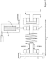
- the SMA engine 1 comprises a SMA actuation core.
- the SMA actuation core is comprised of SMA material clamped or otherwise secured at a first point which is fixed. At the opposing end, the SMA material is clamped or otherwise secured to a drive mechanism 2. Thus whilst the first point is anchored the second point is free to move albeit pulling the drive mechanism 3.
- An immersion chamber 4 is adapted to house the SMA engine and is also adapted to be sequentially filled with fluid to allow heating and/or cooling of the SMA engine. Accordingly, as heat is applied to the SMA core it is free to contract.
- the SMA core comprises a plurality of parallel wires, ribbons or sheets of SMA material.
- a deflection in and around 4% is common for such a core.
- a linear movement of approximately 4cm is available.
- the force that is provided depends on the mass of wire used.
- Such an energy recovery device is described in PCT Patent Publication number WO2013/087490 , assigned to the assignee of the present invention.
- NiTi Nickel-Titanium alloy
- This alloy is a well-known Shape-Memory Alloy and has numerous uses across different industries. It will be appreciated that any suitable SMA or NTE material can be used in the context of the present invention.
- the wire's extremities have to be presented in such a way that they can be securely fixed in a metallic, or other material, support, hereinafter referred to as a bundle holder.
- the invention provides a holder, for use in an energy recovery device, comprising a plurality of slots configured to receive a plurality of Negative Thermal Expansion (NTE) or Shape Memory Alloy (SMA) elements.
- NTE Negative Thermal Expansion
- SMA Shape Memory Alloy
- the swage can be made in two ways, Swage A, 20, and Swage B, 21.
- Swage A is located at the very end of the wire whereas Swage B is located just before the end of the wire, as illustrated in Figure 2 .
- the type of swage used can be determined by the bundle holder or the space which the wire needs to fit into.
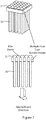
- Figure 3 illustrates a plurality of swaged wires 30 fed into a bundle holder 31 consisting of multiple slots 32 or holes or openings.
- the slots, openings or holes are designed to be smaller in diameter than the swage width, but marginally larger in diameter than the wire 30.
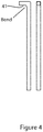
- FIG 4 Another embodiment of the invention is shown in Figure 4 , where a high level of heat is used to place a bend or kink on each end of the wire, indicated by the reference numeral 41. This acts as a stop when the wire 41 is loaded by resting against the surface of a wire bundle holder unit 42, as illustrated in Figure 5 .
- the wires can be lined up beside each other on a single plane, thus facilitating a tightly packed arrangement of wires.
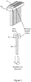
- Figure 6 illustrates another embodiment where one end of the wire 50 is dome shaped 51 to act as a stop when the wire is being held in a bundle or wire holder.
- the domed ends of the wire are larger than the holes in which the wires are placed, thus when a load is applied, the domes 51 act to resist pull-through, as illustrated in Figure 7 .
- the assembly direction of the domes is irrelevant due to their cylindrical nature.
- the energy recovery device can comprise a plurality of Shape Memory Alloy (SMAs) or Negative Thermal Expansion (NTE) elements arranged as a plurality of wires positioned substantially parallel with each other to define a core.
- SMAs Shape Memory Alloy
- NTE Negative Thermal Expansion
- the wires for example, can be those described above with respect to Figures 2 to 7 .
- a large number of SMA wires are required.
- the manufacturing of bundles with a high number of holes in them is expensive and time-consuming and the consistent swaging of the wires is difficult to perform.
- a casting alternative to the machined bundle holder can be used.
- the wires will not need to be swaged as they will be imbedded in a mould.
- Casting is most often used for making complex shapes that would be otherwise difficult or uneconomical to make by other methods. Casting is a manufacturing process by which a liquid material is usually poured into a mould, which contains a hollow cavity of the desired shape, and then allowed to solidify.
- Shape-Memory Alloys contract when heated, while most metals expand.
- a non-reactive material can be selected in this case.
- alloyed materials that have zero thermal expansion while heated.
- the SMA will be at its smallest size (austenitic phase - the diameter of the wire decreases). This process will ensure the fixing of the wire, since the transition from austenite to martensite will result in an increase of diameter, so the cast will act as interference fit.
- Nitinol core In order for a Nitinol core to actuate a piston, a method must be identified for fixing a bundle of wires so that one end is fixed to the top of the core and the other end is attached to the piston.
- Figure 8 shows a proposed way of manufacturing a bundle holder that contains thousands of holes.
- the concept replaces the need for machining solid blocks of material by creating a mesh using wire versions of the same material.
- the wire would be cut into pre-defined lengths. It would then be placed into a jig which would maintain the distance between each wire. This would form a bottom layer.
- Another set of wires would then be placed on top of the first layer; however this layer would be rotated at a 90° angle to the first layer. From a top view this would have the same appearance as a bundle with several holes.
- the next step would be to fuse the top and bottom layer. This would increase the rigidity of the bundle and prevent the gap between wires from increasing or decreasing.
- One way that layers could be fused together would be by using a spot welding technique commonly used to weld panels and thin metals.
- This process consists of an Anode (-) and a Cathode (+).
- the anode is placed on the top layer while the cathode is positioned on the bottom layer.
- the anode and cathode press the two wires together at one junction.
- a current is then passed through the junction which causes it to heat, melt and fuse the wires together. This would be advantageous over drilling holes as a typical spot weld takes 0.63 seconds to fuse the wire. Naturally more time would need to be added to let the weld cool.
- the strength of the bundle holder can be increased by simply adding more layers. This would be particularly advantageous if a part of the bundle holder failed during service as it would allow the bundle holder to be repaired rather than recycled.
- Doming the wires at both ends after it has been cut means that no further work has to be done to the wire.
- These wires are then inserted into a bundle holder which has slots cut out. The width of these slots is equal to the diameter of the wire, which allows the dome at the top of the wire to rest on either side of the slot.
- the wire will be inserted into the bundle holder through a hole that is wider than each dome at the end of every row. This hole will then have a screw threaded into it to hold the wires in place and complete the bundle. This method also allows both the top and bottom layer of the bundle to be inserted at the same time.
- SMAs Shape Memory Alloys
- NTE materials can be used for certain types of applications.
- Shape memory polymers are: polyurethanes, polyurethanes with ionic or mesogenic components made by prepolymer method, block copolymer of polyethylene terephthalate (PET) and polyethyleneoxide (PEO), block copolymers containing polystyrene and poly(1,4-butadiene), and an ABA triblock copolymer made from poly(2-methyl-2-oxazoline) and polytetrahydrofuran, amorphous polynorbornene.
- PET polyethylene terephthalate
- PEO polyethyleneoxide
- ABA triblock copolymer made from poly(2-methyl-2-oxazoline) and polytetrahydrofuran, amorphous polynorbornene.
Landscapes
- Engineering & Computer Science (AREA)
- Chemical & Material Sciences (AREA)
- Combustion & Propulsion (AREA)
- Mechanical Engineering (AREA)
- General Engineering & Computer Science (AREA)
- Springs (AREA)
- Vehicle Cleaning, Maintenance, Repair, Refitting, And Outriggers (AREA)
Claims (7)
- Energierückgewinnungsvorrichtung, die Folgendes umfasst:
eine Kraftmaschine (1), die eine Vielzahl von Elementen aus Formgedächtnislegierung (SMA) oder anderen Elementen mit negativer Wärmeausdehnung (NTE) umfasst, die an einem ersten Ende eingespannt und an einem zweiten Ende mit einem Antriebsmechanismus verbunden sind; wobei eine Immersionskammer (4) dazu angepasst ist, die Kraftmaschine (1) unterzubringen und dazu angepasst ist, der Reihe nach mit Fluid gefüllt zu werden, um das Erwärmen und/oder Abkühlen der Kraftmaschine (1) zu ermöglichen, dadurch gekennzeichnet, dass die Vielzahl von Formgedächtnislegierungs(SMA)-Elementen oder Elementen mit negativer Wärmeausdehnung (NTE) als eine Vielzahl von Drähten (30) angeordnet ist, die im Wesentlichen parallel zueinander positioniert sind, um einen Kern zu definieren, und ein Halter (31) mit einer Vielzahl von Schlitzen (32) konfiguriert ist, die dazu angepasst sind, die Vielzahl von Formgedächtnislegierungs(SMA)- oder NTE-Elementen (30) aufzunehmen, um den Kern während des Betriebs sicher ortsfest zu halten. - Energierückgewinnungsvorrichtung nach Anspruch 1, wobei der Halter (31) eine Platte umfasst, die mit geeignet bemessenen Schlitzen gelocht ist, sodass die Elemente in den Schlitz eingreifen und ortsfest fixiert werden können.
- Energierückgewinnungsvorrichtung nach Anspruch 2, wobei mindestens ein Element ein Stauchabschlussende (20, 21) umfasst, um die Bewegung des Elements einzuschränken, wenn es sich mit dem Halter (31) im Eingriff befindet.
- Energierückgewinnungsvorrichtung nach Anspruch 2, wobei mindestens ein Element ein geknicktes oder gebogenes Ende (41) umfasst, um die Bewegung des Elements einzuschränken, wenn es sich mit dem Halter (42) im Eingriff befindet.
- Energierückgewinnungsvorrichtung nach Anspruch 2, wobei mindestens ein Element (50) ein kuppelförmiges Ende (51) umfasst, um die Bewegung des Elements einzuschränken, wenn es sich mit dem Halter im Eingriff befindet.
- Energierückgewinnungsvorrichtung nach einem der vorangehenden Ansprüche, wobei das Element mit negativer Wärmeausdehnung (NTE) eine Formgedächtnislegierung umfasst.
- Energierückgewinnungsvorrichtung nach Anspruch 6, wobei die Formgedächtnislegierung mindestens eine der Folgenden umfasst: eine Nickel-TitanLegierung, eine Kupfer-Zink-Aluminium-Nickel-Legierung, eine Kupfer-Aluminium-Nickel-Legierung.
Applications Claiming Priority (2)
| Application Number | Priority Date | Filing Date | Title |
|---|---|---|---|
| GBGB1409679.6A GB201409679D0 (en) | 2014-05-30 | 2014-05-30 | Slotted bundle holder for use in an energy recovery device |
| PCT/EP2015/062047 WO2015181388A2 (en) | 2014-05-30 | 2015-05-29 | Bundle holder for use in an energy recovery device |
Publications (2)
| Publication Number | Publication Date |
|---|---|
| EP3149327A2 EP3149327A2 (de) | 2017-04-05 |
| EP3149327B1 true EP3149327B1 (de) | 2019-09-11 |
Family
ID=51214517
Family Applications (1)
| Application Number | Title | Priority Date | Filing Date |
|---|---|---|---|
| EP15731858.5A Active EP3149327B1 (de) | 2014-05-30 | 2015-05-29 | Bündelhalter für eine energierückgewinnungsvorrichtung |
Country Status (5)
| Country | Link |
|---|---|
| US (1) | US9995289B2 (de) |
| EP (1) | EP3149327B1 (de) |
| JP (1) | JP2017530295A (de) |
| GB (1) | GB201409679D0 (de) |
| WO (1) | WO2015181388A2 (de) |
Families Citing this family (7)
| Publication number | Priority date | Publication date | Assignee | Title |
|---|---|---|---|---|
| GB2533335A (en) * | 2014-12-16 | 2016-06-22 | Exergyn Ltd | Heat transfer in an energy recovery device |
| GB201511466D0 (en) * | 2015-06-30 | 2015-08-12 | Exergyn Ltd | SMA bundle wire optimisation in an energy recovery device |
| WO2017156371A1 (en) * | 2016-03-10 | 2017-09-14 | Kellogg's Research Labs | Modular power generator |
| GB201709602D0 (en) * | 2017-06-16 | 2017-08-02 | Exergyn Ltd | Wire forming of shape-memory alloys (SMAs) or negative thermal expansion materials (NTE) for use in an energy recovery system |
| GB201709601D0 (en) * | 2017-06-16 | 2017-08-02 | Exergyn Ltd | Hysteresis manipulation of SMA or NTE Material for use in an energy recovery device |
| GB201714960D0 (en) * | 2017-09-18 | 2017-11-01 | Exergyn Ltd | Hydraulic transmission for an SMA engine used in an energy recovery device |
| GB201820901D0 (en) | 2018-12-20 | 2019-02-06 | Exergyn Ltd | Improvements to wire forming of shape-memory alloys (SMAs) or negative thermal expansion (NTE) materials for use in an energy recovery system |
Citations (1)
| Publication number | Priority date | Publication date | Assignee | Title |
|---|---|---|---|---|
| US20060101807A1 (en) * | 2004-11-12 | 2006-05-18 | Wood Jeffrey H | Morphing structure |
Family Cites Families (8)
| Publication number | Priority date | Publication date | Assignee | Title |
|---|---|---|---|---|
| US4010612A (en) * | 1974-12-13 | 1977-03-08 | Dante J. Sandoval | Thermal motor |
| US4027479A (en) | 1976-05-06 | 1977-06-07 | Cory John S | Variable density heat engine |
| US4231223A (en) * | 1978-06-09 | 1980-11-04 | Pringle William L | Thermal energy scavenger (rotating wire modules) |
| JPS6022079A (ja) | 1983-07-19 | 1985-02-04 | Nhk Spring Co Ltd | 形状記憶合金を用いたヒ−トエンジン |
| JPH05306676A (ja) * | 1992-04-30 | 1993-11-19 | Central Res Inst Of Electric Power Ind | 固相熱エネルギー発電システム |
| US8800282B2 (en) | 2009-11-20 | 2014-08-12 | GM Global Technology Operations LLC | Vehicle energy harvesting device having discrete sections of shape memory alloy |
| GB2497542A (en) | 2011-12-13 | 2013-06-19 | Dublin Inst Of Technology | Shape memory alloy motor with spring energy accumulator |
| JP5656030B2 (ja) * | 2012-08-17 | 2015-01-21 | Smk株式会社 | 駆動装置及びその製造方法 |
-
2014
- 2014-05-30 GB GBGB1409679.6A patent/GB201409679D0/en not_active Ceased
-
2015
- 2015-05-29 EP EP15731858.5A patent/EP3149327B1/de active Active
- 2015-05-29 US US15/315,083 patent/US9995289B2/en active Active
- 2015-05-29 WO PCT/EP2015/062047 patent/WO2015181388A2/en active Application Filing
- 2015-05-29 JP JP2017514975A patent/JP2017530295A/ja not_active Withdrawn
Patent Citations (1)
| Publication number | Priority date | Publication date | Assignee | Title |
|---|---|---|---|---|
| US20060101807A1 (en) * | 2004-11-12 | 2006-05-18 | Wood Jeffrey H | Morphing structure |
Also Published As
| Publication number | Publication date |
|---|---|
| GB201409679D0 (en) | 2014-07-16 |
| WO2015181388A2 (en) | 2015-12-03 |
| WO2015181388A3 (en) | 2016-01-21 |
| US20170198682A1 (en) | 2017-07-13 |
| JP2017530295A (ja) | 2017-10-12 |
| US9995289B2 (en) | 2018-06-12 |
| EP3149327A2 (de) | 2017-04-05 |
Similar Documents
| Publication | Publication Date | Title |
|---|---|---|
| EP3149327B1 (de) | Bündelhalter für eine energierückgewinnungsvorrichtung | |
| EP3230585B1 (de) | Drahtelementanordnung in einer energierückgewinnungsvorrichtung | |
| KR20100101102A (ko) | 로크 링 | |
| EP3234354B1 (de) | Wärmeübertragung in einer energierückgewinnungsvorrichtung | |
| EP3317535A1 (de) | Verfahren und system zur wirkungsgraderhöhung in einer energierückgewinnungsvorrichtung | |
| Prabu et al. | Thermo-mechanical behavior of shape memory alloy spring actuated using novel scanning technique powered by ytterbium doped continuous fiber laser | |
| WO2018229232A1 (en) | Wire forming of shape-memory alloys (smas) or negative thermal expansion (nte) materials for use in an energy recovery system | |
| WO2018002183A1 (en) | Method and system for dynamic balancing of a core in an energy recovery device | |
| US20190316571A1 (en) | Sma bundle piston cushioning system for use in an energy recovery device | |
| EP3670903A1 (de) | Verbesserung der drahtformung von formgedächtnislegierungen (smas) oder von materialien mit negativer wärmeausdehnung zur verwendung in einem energierückgewinnungssystem | |
| US11174849B2 (en) | Hysteresis manipulation of SMA or NTE material for use in an energy recovery device | |
| GB2533163A (en) | Protective element for use in an energy recovery device | |
| John et al. | A Novel Design of Shape-Memory Alloy Actuated Grippers | |
| Czechowicz et al. | Energy Harvesting in Discontinuous Processes by Shape Memory Alloys | |
| Volodymyr et al. | ANALYSIS OF INNOVATIVE DEVICES BASED ON SHAPE MEMORY ALLOYS IN FOOD TECHNOLOGY APPARATUSES | |
| GB2533359A (en) | Reconditioning a core for use in an energy recovery device | |
| WO2019053299A1 (en) | HYDRAULIC TRANSMISSION FOR AN SMA ENGINE USED IN AN ENERGY RECOVERY DEVICE | |
| WO2018229240A1 (en) | Sma material performance boost for use in an energy recovery device | |
| Czechowicz et al. | Benefits of standardization illustrated by shape memory actuators in industrial applications |
Legal Events
| Date | Code | Title | Description |
|---|---|---|---|
| STAA | Information on the status of an ep patent application or granted ep patent |
Free format text: STATUS: THE INTERNATIONAL PUBLICATION HAS BEEN MADE |
|
| PUAI | Public reference made under article 153(3) epc to a published international application that has entered the european phase |
Free format text: ORIGINAL CODE: 0009012 |
|
| STAA | Information on the status of an ep patent application or granted ep patent |
Free format text: STATUS: REQUEST FOR EXAMINATION WAS MADE |
|
| 17P | Request for examination filed |
Effective date: 20161229 |
|
| AK | Designated contracting states |
Kind code of ref document: A2 Designated state(s): AL AT BE BG CH CY CZ DE DK EE ES FI FR GB GR HR HU IE IS IT LI LT LU LV MC MK MT NL NO PL PT RO RS SE SI SK SM TR |
|
| AX | Request for extension of the european patent |
Extension state: BA ME |
|
| DAV | Request for validation of the european patent (deleted) | ||
| DAX | Request for extension of the european patent (deleted) | ||
| STAA | Information on the status of an ep patent application or granted ep patent |
Free format text: STATUS: EXAMINATION IS IN PROGRESS |
|
| 17Q | First examination report despatched |
Effective date: 20180502 |
|
| GRAP | Despatch of communication of intention to grant a patent |
Free format text: ORIGINAL CODE: EPIDOSNIGR1 |
|
| STAA | Information on the status of an ep patent application or granted ep patent |
Free format text: STATUS: GRANT OF PATENT IS INTENDED |
|
| INTG | Intention to grant announced |
Effective date: 20190405 |
|
| GRAS | Grant fee paid |
Free format text: ORIGINAL CODE: EPIDOSNIGR3 |
|
| GRAA | (expected) grant |
Free format text: ORIGINAL CODE: 0009210 |
|
| STAA | Information on the status of an ep patent application or granted ep patent |
Free format text: STATUS: THE PATENT HAS BEEN GRANTED |
|
| AK | Designated contracting states |
Kind code of ref document: B1 Designated state(s): AL AT BE BG CH CY CZ DE DK EE ES FI FR GB GR HR HU IE IS IT LI LT LU LV MC MK MT NL NO PL PT RO RS SE SI SK SM TR |
|
| REG | Reference to a national code |
Ref country code: GB Ref legal event code: FG4D |
|
| REG | Reference to a national code |
Ref country code: CH Ref legal event code: EP |
|
| REG | Reference to a national code |
Ref country code: AT Ref legal event code: REF Ref document number: 1178790 Country of ref document: AT Kind code of ref document: T Effective date: 20190915 |
|
| REG | Reference to a national code |
Ref country code: DE Ref legal event code: R096 Ref document number: 602015037768 Country of ref document: DE Ref country code: IE Ref legal event code: FG4D |
|
| REG | Reference to a national code |
Ref country code: NL Ref legal event code: MP Effective date: 20190911 |
|
| REG | Reference to a national code |
Ref country code: LT Ref legal event code: MG4D |
|
| PG25 | Lapsed in a contracting state [announced via postgrant information from national office to epo] |
Ref country code: HR Free format text: LAPSE BECAUSE OF FAILURE TO SUBMIT A TRANSLATION OF THE DESCRIPTION OR TO PAY THE FEE WITHIN THE PRESCRIBED TIME-LIMIT Effective date: 20190911 Ref country code: LT Free format text: LAPSE BECAUSE OF FAILURE TO SUBMIT A TRANSLATION OF THE DESCRIPTION OR TO PAY THE FEE WITHIN THE PRESCRIBED TIME-LIMIT Effective date: 20190911 Ref country code: FI Free format text: LAPSE BECAUSE OF FAILURE TO SUBMIT A TRANSLATION OF THE DESCRIPTION OR TO PAY THE FEE WITHIN THE PRESCRIBED TIME-LIMIT Effective date: 20190911 Ref country code: NO Free format text: LAPSE BECAUSE OF FAILURE TO SUBMIT A TRANSLATION OF THE DESCRIPTION OR TO PAY THE FEE WITHIN THE PRESCRIBED TIME-LIMIT Effective date: 20191211 Ref country code: SE Free format text: LAPSE BECAUSE OF FAILURE TO SUBMIT A TRANSLATION OF THE DESCRIPTION OR TO PAY THE FEE WITHIN THE PRESCRIBED TIME-LIMIT Effective date: 20190911 Ref country code: BG Free format text: LAPSE BECAUSE OF FAILURE TO SUBMIT A TRANSLATION OF THE DESCRIPTION OR TO PAY THE FEE WITHIN THE PRESCRIBED TIME-LIMIT Effective date: 20191211 |
|
| PG25 | Lapsed in a contracting state [announced via postgrant information from national office to epo] |
Ref country code: RS Free format text: LAPSE BECAUSE OF FAILURE TO SUBMIT A TRANSLATION OF THE DESCRIPTION OR TO PAY THE FEE WITHIN THE PRESCRIBED TIME-LIMIT Effective date: 20190911 Ref country code: ES Free format text: LAPSE BECAUSE OF FAILURE TO SUBMIT A TRANSLATION OF THE DESCRIPTION OR TO PAY THE FEE WITHIN THE PRESCRIBED TIME-LIMIT Effective date: 20190911 Ref country code: AL Free format text: LAPSE BECAUSE OF FAILURE TO SUBMIT A TRANSLATION OF THE DESCRIPTION OR TO PAY THE FEE WITHIN THE PRESCRIBED TIME-LIMIT Effective date: 20190911 Ref country code: LV Free format text: LAPSE BECAUSE OF FAILURE TO SUBMIT A TRANSLATION OF THE DESCRIPTION OR TO PAY THE FEE WITHIN THE PRESCRIBED TIME-LIMIT Effective date: 20190911 Ref country code: GR Free format text: LAPSE BECAUSE OF FAILURE TO SUBMIT A TRANSLATION OF THE DESCRIPTION OR TO PAY THE FEE WITHIN THE PRESCRIBED TIME-LIMIT Effective date: 20191212 |
|
| REG | Reference to a national code |
Ref country code: AT Ref legal event code: MK05 Ref document number: 1178790 Country of ref document: AT Kind code of ref document: T Effective date: 20190911 |
|
| PG25 | Lapsed in a contracting state [announced via postgrant information from national office to epo] |
Ref country code: NL Free format text: LAPSE BECAUSE OF FAILURE TO SUBMIT A TRANSLATION OF THE DESCRIPTION OR TO PAY THE FEE WITHIN THE PRESCRIBED TIME-LIMIT Effective date: 20190911 Ref country code: AT Free format text: LAPSE BECAUSE OF FAILURE TO SUBMIT A TRANSLATION OF THE DESCRIPTION OR TO PAY THE FEE WITHIN THE PRESCRIBED TIME-LIMIT Effective date: 20190911 Ref country code: PT Free format text: LAPSE BECAUSE OF FAILURE TO SUBMIT A TRANSLATION OF THE DESCRIPTION OR TO PAY THE FEE WITHIN THE PRESCRIBED TIME-LIMIT Effective date: 20200113 Ref country code: PL Free format text: LAPSE BECAUSE OF FAILURE TO SUBMIT A TRANSLATION OF THE DESCRIPTION OR TO PAY THE FEE WITHIN THE PRESCRIBED TIME-LIMIT Effective date: 20190911 Ref country code: IT Free format text: LAPSE BECAUSE OF FAILURE TO SUBMIT A TRANSLATION OF THE DESCRIPTION OR TO PAY THE FEE WITHIN THE PRESCRIBED TIME-LIMIT Effective date: 20190911 Ref country code: RO Free format text: LAPSE BECAUSE OF FAILURE TO SUBMIT A TRANSLATION OF THE DESCRIPTION OR TO PAY THE FEE WITHIN THE PRESCRIBED TIME-LIMIT Effective date: 20190911 Ref country code: EE Free format text: LAPSE BECAUSE OF FAILURE TO SUBMIT A TRANSLATION OF THE DESCRIPTION OR TO PAY THE FEE WITHIN THE PRESCRIBED TIME-LIMIT Effective date: 20190911 |
|
| PG25 | Lapsed in a contracting state [announced via postgrant information from national office to epo] |
Ref country code: SM Free format text: LAPSE BECAUSE OF FAILURE TO SUBMIT A TRANSLATION OF THE DESCRIPTION OR TO PAY THE FEE WITHIN THE PRESCRIBED TIME-LIMIT Effective date: 20190911 Ref country code: IS Free format text: LAPSE BECAUSE OF FAILURE TO SUBMIT A TRANSLATION OF THE DESCRIPTION OR TO PAY THE FEE WITHIN THE PRESCRIBED TIME-LIMIT Effective date: 20200224 Ref country code: CZ Free format text: LAPSE BECAUSE OF FAILURE TO SUBMIT A TRANSLATION OF THE DESCRIPTION OR TO PAY THE FEE WITHIN THE PRESCRIBED TIME-LIMIT Effective date: 20190911 Ref country code: SK Free format text: LAPSE BECAUSE OF FAILURE TO SUBMIT A TRANSLATION OF THE DESCRIPTION OR TO PAY THE FEE WITHIN THE PRESCRIBED TIME-LIMIT Effective date: 20190911 |
|
| REG | Reference to a national code |
Ref country code: DE Ref legal event code: R097 Ref document number: 602015037768 Country of ref document: DE |
|
| PLBE | No opposition filed within time limit |
Free format text: ORIGINAL CODE: 0009261 |
|
| STAA | Information on the status of an ep patent application or granted ep patent |
Free format text: STATUS: NO OPPOSITION FILED WITHIN TIME LIMIT |
|
| PG2D | Information on lapse in contracting state deleted |
Ref country code: IS |
|
| PG25 | Lapsed in a contracting state [announced via postgrant information from national office to epo] |
Ref country code: DK Free format text: LAPSE BECAUSE OF FAILURE TO SUBMIT A TRANSLATION OF THE DESCRIPTION OR TO PAY THE FEE WITHIN THE PRESCRIBED TIME-LIMIT Effective date: 20190911 Ref country code: IS Free format text: LAPSE BECAUSE OF FAILURE TO SUBMIT A TRANSLATION OF THE DESCRIPTION OR TO PAY THE FEE WITHIN THE PRESCRIBED TIME-LIMIT Effective date: 20200112 |
|
| 26N | No opposition filed |
Effective date: 20200615 |
|
| PG25 | Lapsed in a contracting state [announced via postgrant information from national office to epo] |
Ref country code: SI Free format text: LAPSE BECAUSE OF FAILURE TO SUBMIT A TRANSLATION OF THE DESCRIPTION OR TO PAY THE FEE WITHIN THE PRESCRIBED TIME-LIMIT Effective date: 20190911 |
|
| PG25 | Lapsed in a contracting state [announced via postgrant information from national office to epo] |
Ref country code: MC Free format text: LAPSE BECAUSE OF FAILURE TO SUBMIT A TRANSLATION OF THE DESCRIPTION OR TO PAY THE FEE WITHIN THE PRESCRIBED TIME-LIMIT Effective date: 20190911 Ref country code: LI Free format text: LAPSE BECAUSE OF NON-PAYMENT OF DUE FEES Effective date: 20200531 Ref country code: CH Free format text: LAPSE BECAUSE OF NON-PAYMENT OF DUE FEES Effective date: 20200531 |
|
| REG | Reference to a national code |
Ref country code: BE Ref legal event code: MM Effective date: 20200531 |
|
| PG25 | Lapsed in a contracting state [announced via postgrant information from national office to epo] |
Ref country code: LU Free format text: LAPSE BECAUSE OF NON-PAYMENT OF DUE FEES Effective date: 20200529 |
|
| PG25 | Lapsed in a contracting state [announced via postgrant information from national office to epo] |
Ref country code: BE Free format text: LAPSE BECAUSE OF NON-PAYMENT OF DUE FEES Effective date: 20200531 |
|
| PGFP | Annual fee paid to national office [announced via postgrant information from national office to epo] |
Ref country code: IE Payment date: 20220328 Year of fee payment: 8 Ref country code: GB Payment date: 20220328 Year of fee payment: 8 |
|
| PG25 | Lapsed in a contracting state [announced via postgrant information from national office to epo] |
Ref country code: TR Free format text: LAPSE BECAUSE OF FAILURE TO SUBMIT A TRANSLATION OF THE DESCRIPTION OR TO PAY THE FEE WITHIN THE PRESCRIBED TIME-LIMIT Effective date: 20190911 Ref country code: MT Free format text: LAPSE BECAUSE OF FAILURE TO SUBMIT A TRANSLATION OF THE DESCRIPTION OR TO PAY THE FEE WITHIN THE PRESCRIBED TIME-LIMIT Effective date: 20190911 Ref country code: CY Free format text: LAPSE BECAUSE OF FAILURE TO SUBMIT A TRANSLATION OF THE DESCRIPTION OR TO PAY THE FEE WITHIN THE PRESCRIBED TIME-LIMIT Effective date: 20190911 |
|
| PG25 | Lapsed in a contracting state [announced via postgrant information from national office to epo] |
Ref country code: MK Free format text: LAPSE BECAUSE OF FAILURE TO SUBMIT A TRANSLATION OF THE DESCRIPTION OR TO PAY THE FEE WITHIN THE PRESCRIBED TIME-LIMIT Effective date: 20190911 |
|
| PGFP | Annual fee paid to national office [announced via postgrant information from national office to epo] |
Ref country code: FR Payment date: 20220511 Year of fee payment: 8 Ref country code: DE Payment date: 20220531 Year of fee payment: 8 |
|
| P01 | Opt-out of the competence of the unified patent court (upc) registered |
Effective date: 20230601 |
|
| REG | Reference to a national code |
Ref country code: DE Ref legal event code: R119 Ref document number: 602015037768 Country of ref document: DE |
|
| GBPC | Gb: european patent ceased through non-payment of renewal fee |
Effective date: 20230529 |
|
| REG | Reference to a national code |
Ref country code: IE Ref legal event code: MM4A |
|
| PG25 | Lapsed in a contracting state [announced via postgrant information from national office to epo] |
Ref country code: IE Free format text: LAPSE BECAUSE OF NON-PAYMENT OF DUE FEES Effective date: 20230529 |
|
| PG25 | Lapsed in a contracting state [announced via postgrant information from national office to epo] |
Ref country code: IE Free format text: LAPSE BECAUSE OF NON-PAYMENT OF DUE FEES Effective date: 20230529 Ref country code: DE Free format text: LAPSE BECAUSE OF NON-PAYMENT OF DUE FEES Effective date: 20231201 Ref country code: GB Free format text: LAPSE BECAUSE OF NON-PAYMENT OF DUE FEES Effective date: 20230529 |