EP3149249B1 - Locking device for securing a wear member - Google Patents
Locking device for securing a wear member Download PDFInfo
- Publication number
- EP3149249B1 EP3149249B1 EP15725019.2A EP15725019A EP3149249B1 EP 3149249 B1 EP3149249 B1 EP 3149249B1 EP 15725019 A EP15725019 A EP 15725019A EP 3149249 B1 EP3149249 B1 EP 3149249B1
- Authority
- EP
- European Patent Office
- Prior art keywords
- spring
- locking
- locking element
- locking device
- housing
- Prior art date
- Legal status (The legal status is an assumption and is not a legal conclusion. Google has not performed a legal analysis and makes no representation as to the accuracy of the status listed.)
- Active
Links
- 239000002775 capsule Substances 0.000 claims description 104
- 230000008859 change Effects 0.000 claims description 10
- 238000000034 method Methods 0.000 claims description 8
- 230000008569 process Effects 0.000 claims description 6
- 238000003780 insertion Methods 0.000 claims description 3
- 230000037431 insertion Effects 0.000 claims description 3
- 230000001419 dependent effect Effects 0.000 claims 5
- 230000008878 coupling Effects 0.000 description 18
- 238000010168 coupling process Methods 0.000 description 18
- 238000005859 coupling reaction Methods 0.000 description 18
- 210000001331 nose Anatomy 0.000 description 9
- 230000008901 benefit Effects 0.000 description 8
- 239000000463 material Substances 0.000 description 8
- 229910000831 Steel Inorganic materials 0.000 description 6
- 239000010959 steel Substances 0.000 description 6
- 238000004519 manufacturing process Methods 0.000 description 4
- 239000013536 elastomeric material Substances 0.000 description 3
- 210000000887 face Anatomy 0.000 description 3
- 238000009434 installation Methods 0.000 description 3
- 241000602850 Cinclidae Species 0.000 description 2
- 230000009471 action Effects 0.000 description 2
- 230000000903 blocking effect Effects 0.000 description 2
- 230000000295 complement effect Effects 0.000 description 2
- 230000006835 compression Effects 0.000 description 2
- 238000007906 compression Methods 0.000 description 2
- 239000013013 elastic material Substances 0.000 description 2
- 238000005065 mining Methods 0.000 description 2
- 239000000843 powder Substances 0.000 description 2
- 230000001012 protector Effects 0.000 description 2
- OKTJSMMVPCPJKN-UHFFFAOYSA-N Carbon Chemical compound [C] OKTJSMMVPCPJKN-UHFFFAOYSA-N 0.000 description 1
- 229910052799 carbon Inorganic materials 0.000 description 1
- 238000006243 chemical reaction Methods 0.000 description 1
- 230000003247 decreasing effect Effects 0.000 description 1
- 230000007547 defect Effects 0.000 description 1
- 238000006073 displacement reaction Methods 0.000 description 1
- 230000000694 effects Effects 0.000 description 1
- 238000000605 extraction Methods 0.000 description 1
- 229910052500 inorganic mineral Inorganic materials 0.000 description 1
- 238000003754 machining Methods 0.000 description 1
- 238000012423 maintenance Methods 0.000 description 1
- 239000011707 mineral Substances 0.000 description 1
- 230000035515 penetration Effects 0.000 description 1
- 230000008439 repair process Effects 0.000 description 1
- 239000011435 rock Substances 0.000 description 1
- 239000007787 solid Substances 0.000 description 1
- 238000003466 welding Methods 0.000 description 1
Images


Classifications
-
- E—FIXED CONSTRUCTIONS
- E02—HYDRAULIC ENGINEERING; FOUNDATIONS; SOIL SHIFTING
- E02F—DREDGING; SOIL-SHIFTING
- E02F9/00—Component parts of dredgers or soil-shifting machines, not restricted to one of the kinds covered by groups E02F3/00 - E02F7/00
- E02F9/28—Small metalwork for digging elements, e.g. teeth scraper bits
- E02F9/2808—Teeth
- E02F9/2816—Mountings therefor
- E02F9/2833—Retaining means, e.g. pins
-
- E—FIXED CONSTRUCTIONS
- E02—HYDRAULIC ENGINEERING; FOUNDATIONS; SOIL SHIFTING
- E02F—DREDGING; SOIL-SHIFTING
- E02F9/00—Component parts of dredgers or soil-shifting machines, not restricted to one of the kinds covered by groups E02F3/00 - E02F7/00
- E02F9/28—Small metalwork for digging elements, e.g. teeth scraper bits
- E02F9/2808—Teeth
- E02F9/2816—Mountings therefor
- E02F9/2825—Mountings therefor using adapters
-
- E—FIXED CONSTRUCTIONS
- E02—HYDRAULIC ENGINEERING; FOUNDATIONS; SOIL SHIFTING
- E02F—DREDGING; SOIL-SHIFTING
- E02F9/00—Component parts of dredgers or soil-shifting machines, not restricted to one of the kinds covered by groups E02F3/00 - E02F7/00
- E02F9/28—Small metalwork for digging elements, e.g. teeth scraper bits
- E02F9/2808—Teeth
- E02F9/2816—Mountings therefor
- E02F9/2833—Retaining means, e.g. pins
- E02F9/2841—Retaining means, e.g. pins resilient
-
- E—FIXED CONSTRUCTIONS
- E02—HYDRAULIC ENGINEERING; FOUNDATIONS; SOIL SHIFTING
- E02F—DREDGING; SOIL-SHIFTING
- E02F9/00—Component parts of dredgers or soil-shifting machines, not restricted to one of the kinds covered by groups E02F3/00 - E02F7/00
- E02F9/28—Small metalwork for digging elements, e.g. teeth scraper bits
- E02F9/2883—Wear elements for buckets or implements in general
-
- E—FIXED CONSTRUCTIONS
- E02—HYDRAULIC ENGINEERING; FOUNDATIONS; SOIL SHIFTING
- E02F—DREDGING; SOIL-SHIFTING
- E02F9/00—Component parts of dredgers or soil-shifting machines, not restricted to one of the kinds covered by groups E02F3/00 - E02F7/00
- E02F9/28—Small metalwork for digging elements, e.g. teeth scraper bits
- E02F9/2891—Tools for assembling or disassembling
-
- E—FIXED CONSTRUCTIONS
- E21—EARTH DRILLING; MINING
- E21C—MINING OR QUARRYING
- E21C35/00—Details of, or accessories for, machines for slitting or completely freeing the mineral from the seam, not provided for in groups E21C25/00 - E21C33/00, E21C37/00 or E21C39/00
- E21C35/18—Mining picks; Holders therefor
- E21C35/19—Means for fixing picks or holders
- E21C35/193—Means for fixing picks or holders using bolts as main fixing elements
-
- E—FIXED CONSTRUCTIONS
- E21—EARTH DRILLING; MINING
- E21C—MINING OR QUARRYING
- E21C35/00—Details of, or accessories for, machines for slitting or completely freeing the mineral from the seam, not provided for in groups E21C25/00 - E21C33/00, E21C37/00 or E21C39/00
- E21C35/18—Mining picks; Holders therefor
- E21C35/19—Means for fixing picks or holders
- E21C35/197—Means for fixing picks or holders using sleeves, rings or the like, as main fixing elements
-
- F—MECHANICAL ENGINEERING; LIGHTING; HEATING; WEAPONS; BLASTING
- F16—ENGINEERING ELEMENTS AND UNITS; GENERAL MEASURES FOR PRODUCING AND MAINTAINING EFFECTIVE FUNCTIONING OF MACHINES OR INSTALLATIONS; THERMAL INSULATION IN GENERAL
- F16B—DEVICES FOR FASTENING OR SECURING CONSTRUCTIONAL ELEMENTS OR MACHINE PARTS TOGETHER, e.g. NAILS, BOLTS, CIRCLIPS, CLAMPS, CLIPS OR WEDGES; JOINTS OR JOINTING
- F16B21/00—Means for preventing relative axial movement of a pin, spigot, shaft or the like and a member surrounding it; Stud-and-socket releasable fastenings
- F16B21/10—Means for preventing relative axial movement of a pin, spigot, shaft or the like and a member surrounding it; Stud-and-socket releasable fastenings by separate parts
- F16B21/12—Means for preventing relative axial movement of a pin, spigot, shaft or the like and a member surrounding it; Stud-and-socket releasable fastenings by separate parts with locking-pins or split-pins thrust into holes
- F16B21/125—Means for preventing relative axial movement of a pin, spigot, shaft or the like and a member surrounding it; Stud-and-socket releasable fastenings by separate parts with locking-pins or split-pins thrust into holes radially resilient or with a snap-action member, e.g. elastic tooth, pawl with spring, resilient coil or wire
-
- F—MECHANICAL ENGINEERING; LIGHTING; HEATING; WEAPONS; BLASTING
- F16—ENGINEERING ELEMENTS AND UNITS; GENERAL MEASURES FOR PRODUCING AND MAINTAINING EFFECTIVE FUNCTIONING OF MACHINES OR INSTALLATIONS; THERMAL INSULATION IN GENERAL
- F16B—DEVICES FOR FASTENING OR SECURING CONSTRUCTIONAL ELEMENTS OR MACHINE PARTS TOGETHER, e.g. NAILS, BOLTS, CIRCLIPS, CLAMPS, CLIPS OR WEDGES; JOINTS OR JOINTING
- F16B19/00—Bolts without screw-thread; Pins, including deformable elements; Rivets
- F16B19/02—Bolts or sleeves for positioning of machine parts, e.g. notched taper pins, fitting pins, sleeves, eccentric positioning rings
-
- F—MECHANICAL ENGINEERING; LIGHTING; HEATING; WEAPONS; BLASTING
- F16—ENGINEERING ELEMENTS AND UNITS; GENERAL MEASURES FOR PRODUCING AND MAINTAINING EFFECTIVE FUNCTIONING OF MACHINES OR INSTALLATIONS; THERMAL INSULATION IN GENERAL
- F16B—DEVICES FOR FASTENING OR SECURING CONSTRUCTIONAL ELEMENTS OR MACHINE PARTS TOGETHER, e.g. NAILS, BOLTS, CIRCLIPS, CLAMPS, CLIPS OR WEDGES; JOINTS OR JOINTING
- F16B21/00—Means for preventing relative axial movement of a pin, spigot, shaft or the like and a member surrounding it; Stud-and-socket releasable fastenings
- F16B21/06—Releasable fastening devices with snap-action
- F16B21/08—Releasable fastening devices with snap-action in which the stud, pin, or spigot has a resilient part
- F16B21/082—Releasable fastening devices with snap-action in which the stud, pin, or spigot has a resilient part the stud, pin or spigot having two resilient parts on its opposite ends in order to connect two elements
-
- F—MECHANICAL ENGINEERING; LIGHTING; HEATING; WEAPONS; BLASTING
- F16—ENGINEERING ELEMENTS AND UNITS; GENERAL MEASURES FOR PRODUCING AND MAINTAINING EFFECTIVE FUNCTIONING OF MACHINES OR INSTALLATIONS; THERMAL INSULATION IN GENERAL
- F16B—DEVICES FOR FASTENING OR SECURING CONSTRUCTIONAL ELEMENTS OR MACHINE PARTS TOGETHER, e.g. NAILS, BOLTS, CIRCLIPS, CLAMPS, CLIPS OR WEDGES; JOINTS OR JOINTING
- F16B37/00—Nuts or like thread-engaging members
- F16B37/12—Nuts or like thread-engaging members with thread-engaging surfaces formed by inserted coil-springs, discs, or the like; Independent pieces of wound wire used as nuts; Threaded inserts for holes
- F16B37/122—Threaded inserts, e.g. "rampa bolts"
- F16B37/125—Threaded inserts, e.g. "rampa bolts" the external surface of the insert being threaded
Definitions
- the invention relates to a locking device for securing a wear part (also named wear member) in a corresponding support (or adapter) for excavators and similar machines, where the support comprises a housing and the wear part comprises an orifice so that, in a mounted position, the housing and the orifice are at least partially overlapped, where the locking device is able to be introduced in the housing.
- a wear part also named wear member
- the support comprises a housing and the wear part comprises an orifice so that, in a mounted position, the housing and the orifice are at least partially overlapped, where the locking device is able to be introduced in the housing.
- the invention relates also to a wearable system comprising a wear part, a support and a locking device, where the support comprises a housing and the wear part comprises an orifice so that, in a mounted position, the housing and the orifice are at least partially overlapped, where the locking device is able to be introduced in the housing.
- the present disclosure relates additionally to a wearable system comprising a wear part, and a support, where the support comprises a housing and the wear part comprises an orifice so that, in a mounted position, the housing and the orifice are at least partially overlapped.
- the invention relates also to a process for fixing a wear part in a support with a locking device, where the support comprises a housing and the wear part comprises an orifice so that, in a mounted position, the housing and the orifice are at least partially overlapped, where the locking device is able to be introduced in the housing, the locking device comprising:
- Earthmoving machinery used for excavating, loading and moving materials such as rocks, sands, overburden and minerals
- the bucket or dipper is provided with a blade or lip on its front edge intended to penetrate the ground and load the material.
- wear parts or wear members on the lip such as teeth, adapters (tooth holders), lip protectors and side protectors.
- wear parts or wear members are subject to wear and stress that can deteriorate them.
- Bucket teeth are usually the most exposed wear parts having to be frequently replaced.
- these machines may work in a wide range of applications, where changing the tooth design might be necessary to improve the performance of the bucket.
- These wear parts can be attached to other wear parts (such as a tooth attached to an adapter) and can be attached to the blade or lip (such as an adapter attached to a lip).
- the mechanical coupling between wear parts is usually done through a retaining element, for example a locking device or pin.
- Two types of wear can be distinguished: the outer wear of the parts due to the flow of the excavated or loaded material, and the inner wear due to the material (dirt, fines) that is introduced between the wear parts coupling (for example between the tooth and the adapter).
- This material located inside the coupling between two mechanical parts increases the wear of the inner areas of such parts, due to the movement between these parts while the bucket is in operation.
- a tooth with an average wear life performs more than 50,000 work cycles; as a result, the coupling must be designed to prevent the defects generated due to the fatigue phenomena, such as cracks, to be compatible with the plastic deformation of wear parts that happens due to the stress reactions generated to counteract the forces suffered by the wear parts, etc.
- the bearing surfaces of adapters are the most affected by the inner wear and plastic deformation because the steel used on adapters usually has a lower hardness than the steel used on teeth.
- Large earthmoving machines, especially those operating in quarries and mines, are essential for the production of the sites. Downtime on these machines due to a lost or broken part can be very costly for the customers.
- a lost or broken part can end up inside the crusher too, damaging and disabling this critical installation and resulting on a very expensive repair.
- a lost or broken wear part (also the change of the wear part when it is worn out, because it is important to change the tooth before it broke or wear out) will also require stopping the machine to assemble another part, resulting on wasted production time. For all these reasons, it is critical to make sure that wear parts do not break or fall off from the buckets or dippers.
- Teeth are manufactured with steels with a hardness between 450-550 HB to maximize their wear life.
- Adapters that have to be welded on lips cannot be produced as the same steels as teeth because it would be extremely difficult and risky to weld them on the lips; these adapters are usually manufactured with steels with lower carbon content, obtaining a hardness between 300-400 HB, resulting on an Ceq ⁇ 0,7, guaranteeing its weldability.
- Large earthmoving machines such as mining rope shovels, draglines and large hydraulic excavators are commonly equipped with cast lips (blades with integrated cast noses).
- the locking device or pin has to be safe and easy to assemble and disassemble allowing a quick change of the wear member.
- the safety of the operators is extremely important and the machine's downtime must be reduced as much as possible to maximize its operating time, so the needed time to replace teeth has to be minimized.
- Conventional locking devices require a hammer to assemble and disassemble the pin. In order to make this procedure safe an easy, a hammerless locking system is desirable. This means that the pin has to be assembled and disassembled in a hammerless manner, i.e., without needing a hammer for introducing or removing the pin.
- Document DE 202011101484 U1 describes a pin comprising a capsule with a spring within, for coupling a tooth on a tooth holder, where the pin has to be introduced in a housing in the tooth holder with the help of a special tool. This tool compresses the spring in the housing and maintains it compressed during the coupling of the tooth on the tooth holder, making the assembly difficult and unsafe. Further, the described pin makes it difficult to replace a tooth once it is worn out, as there are no means to compress the spring once it is introduced in the housing of the tooth holder. On the other hand the spring cannot be fixed to the housing, so it can be compressed undesirably during operation, and therefore the tooth could fall off while the bucket is digging or leading material. A similar device is described in US 2010/0257759 A1 .
- Document GB 2.151.284 describes a device for retaining a cutter pick in a pick box in which an helical fastening member of circular section is used for forming a thread between two elements.
- Document US 3.030.088 describes a locking device with a locking element in which a helical spring pushes the locking element to an extended position, whereas an external force can push the locking element to a retracted position.
- an important feature of the invention is that the pin system has been designed to reduce and eliminate the gap produced by the inner wear and plastic deformation, recovering the contact between the bearing surfaces of the tooth and the adapter. This feature will allow the coupling to operate with no gap because the locking device will adapt itself to the new contact areas between the wear parts. This means that the locking device adapts itself to the new contact areas automatically, without the need of having an operator stopping the machine to retighten and reposition the locking system. This offers greater reliability, allowing an optimum fit between all parts.
- the present invention also intends to obtain a locking device or pin that is safe and easy to assemble and disassemble allowing a quick change out of the wear parts through a hammerless-style locking device. In addition, it targets to have less components (reducing the cost and the risk of failure).
- the support comprises a housing and the wear part comprises an orifice so that, in a mounted position, the housing and the orifice are at least partially overlapped, where the locking device is able to be introduced in the housing, where, in the mounted position, the locking end at least partially emerges from the housing and penetrates into the orifice.
- the locking device allows an easy assembly and disassembly, without the need of a hammer and with a reduced number of components.
- the helical spring takes benefit of its helical form and is directly threaded on a thread, allowing the axial displacement of the spring (which will force also the movement of the locking element along said axis), which allows a plurality of advantages as will be shown below.
- the length of the locking element and the spring in an at least partially threaded position in the thread is smaller or equal than the length of the housing. So, the operator will introduce the locking element in this at least partially threaded position in the housing and, as the locking element will not protrude outside from the housing, the operator will be able to put the wear part over the support without any opposing force exerted by the locking element.
- the length of the locking element and the spring in a completely threaded position in the thread is smaller or equal than the length of the housing.
- the locking element and the spring are threaded together, so that the spring works both as a screw and as a spring, allowing the locking element to resize itself, varying its length, depending of the wearing conditions between the wear member and the adapter. This set up also prevents the locking device from unintentionally unblocking itself during operation due to an undesirable compression of the spring.
- the coupling between the wear member or tooth, usually a "female part” in the sense that it has a hole in which a nose from the adapter is introduced, and the adapter or tooth holder, usually a "male part” in the sense that it has a nose that is introduced inside a hole present in the wear member, as well as the uncoupling, are performed in a simple way, from the outside, without the need to use special tools or apply strong forces on the locking device, which can be dangerous. At the same time it provides solid and reliable coupling while working due to the fact that the locking device or pin can absorb slight movements of the wear member over the adapter and auto-adjusts its length.
- the locking device explained also would be used in three part systems. These three part system consist of a point, an intermediate part and a weld or cast adapter.
- the cast or weld adapter is provided with the male part
- the intermediate part is provided with a female part on the back and with a male part on the front and the point is provided with another female part.
- the locking device is first introduced in a housing of the adapter with the locking end facing the outside of the adapter and the base of the spring inside the housing.
- the locking device is introduced into a housing of the adapter, it will also be feasible introduced into a housing of the wear member.
- the spring is in a fixed position and the thread is moved by the action of the operator so that the spring screws or unscrews from the thread, whereas in another alternative what is fixed is the thread and the spring is moved by the action of the operator.
- both alternatives allow the design of advantageous solutions. In any case the screwing or unscrewing of the spring from the thread tends to move the locking element in an axial direction.
- the spring is directly fixed to said support.
- the thread may be positioned in a plurality of components or places of the locking device, each of them allowing a different fixing of the spring so that it can be screwed and unscrewed from the thread.
- the spring is fixed, for example, to the housing by welding or using means or interconnections that are included in the housing, in order to prevent the rotation of the spring around its axis when it is screwed or unscrewed to the thread.
- the locking device has a minimum of parts.
- the locking device comprises, additionally, a supporting body, able to be allocated in the bottom of the housing, and the spring is fixed in respect of the supporting body in order to prevent its rotation in respect of the supporting body.
- the locking end comprises a bearing surface that form a non-zero angle with said longitudinal axis, where, in said mounted position, the bearing surface is in contact with a corresponding bearing surface present in the orifice.
- one aim of the present invention is to obtain a reliable assembly between wear parts (especially between teeth and adapters, and between adapters and cast noses) cancelling the negative effects of the gap generated by plastic deformation and/or the wear in-between the coupling, plus compensating the gaps due to the manufacturing tolerances between wear parts.
- the locking device or pin object of the present invention intends to correct the misalignments between the fitting or coupling of wear parts produced by plastic deformation, inner wear and also due to manufacturing tolerances. With this preferred solution this problem is solved, as the locking device assures always a full contact between both bearing surfaces and presses constantly the tooth against the adapter, also if the wearing of these parts changes their geometries.
- the bearing surface of the locking element is preferably complementary in shape with the corresponding bearing surface of the orifice so that a better contact between both is achieved.
- the locking end of the locking element has preferably a truncated cone shape.
- a preferred embodiment has a locking element with a locking end which bearing surface shaped as a truncated cone and an orifice with a bearing surface which is a flat surface, where the angle of the truncated cone and the angle between the flat surface and the axis of the cone (in a mounted position) are the same, so that the contact between the truncated cone and the flat surface is along a generatrix of the truncated cone.
- the supporting body comprises a guide or shaft introduced in the spring. This allows guiding the spring, maintaining it in an axial position, avoiding axial movements and giving the spring more stability.
- the supporting body comprises lateral walls defining a capsule, able to accommodate at least partially said locking element.
- the supporting body is like a tube with a closed end (the base of the supporting body) and lateral walls that define a capsule where the locking element can be allocated.
- the locking device comprises a capsule, able to accommodate at least partially the locking element, where the supporting body is fixed to one end of the capsule.
- the capsule isolates the spring and the thread from debris, powder, etc.
- the supporting body and the capsule are formed as one single part, reducing the quantity of parts of the locking device.
- the capsule comprises anti-rotation means able to avoid the rotation of the supporting body in respect of the housing in the mounted position. This prevents that the whole locking device rotates respect the housing in the adapter when the spring is screwed or unscrewed from the thread.
- the anti-rotation means comprises a wall extending parallel to the longitudinal axis. It can be positioned, for example, on the outer lateral surface of the capsule or on the lower surface of the base of the supporting body. This last alternative allows reducing the overall diameter of the locking device.
- the locking device comprises ejection means that includes a helicoidal wall, which is coaxial with the longitudinal axis. It can also be positioned on the outer lateral surface of the capsule or on the lower surface of the base of the supporting body.
- the thread can be allocated in different parts of the locking device.
- One preferred alternative is that the thread is on the locking element.
- the thread can be in the outer surface of the locking element (so that the spring screws over the locking element) or it can be in the inner surface of an inner cavity foreseen in the locking element, the inner cavity being axially oriented and opened at the end opposite to the locking end.
- the spring will be allocated at least partially inside the inner cavity and the thread will be over the spring.
- Another preferred alternative is to include the thread on the guide (on the external surface from the guide). In this case, the spring will screw over the thread.
- the locking device has stopping means able to avoid that the locking element can go out completely from the capsule, so avoiding the possible loss of the locking element during the assembly or during operation.
- the stopping means comprises a first stopping surface in the outer surface of the locking element and a second stopping surface in the inner surface of the capsule, so that the first stopping surface is longer in a radial direction respect of the longitudinal axis than the remaining part of said outer surface of the locking element and so that the second stopping surface protrudes out of the remaining part of the inner surface of the capsule.
- Both the first stopping surface and the second stopping surface are preferably annular surfaces, so that they offer a big contact surface between them.
- stopping means can include a pin (preferably a screw) inserted in the lateral wall of the capsule so that its end projects in the interior of the cavity defined by the capsule and in the interior of a lateral groove foreseen in the lateral surface of the locking element.
- a pin preferably a screw
- the locking element has an annular groove and a tightening ring inserted in it. So, the interior of the capsule can be better isolated from the debris, powder, etc.
- the locking device comprises a second locking element, opposed to the locking element, and a second spring, opposed to the spring.
- the housing of the adapter is a through hole and the capsule or the supporting body comprises a second bearing surface, so that both bearing surfaces can project outside of the housing at both ends of it.
- Other possible alternatives are providing a supporting body with two opposed capsules, each of them including a locking member according to the invention.
- a third possible solution could be, for example, simply using two locking devices according to the invention in two opposed housings, which may be internally connected or not.
- the locking device only locks one side of the wear part and adapter system, this might cause that the wear part inclines or tilts in working conditions.
- the double locking device extends along all the width of the adapter, improving the stability of the system. Furthermore the diameter of the locking device could be smaller and the strength of the nose of the adapter is better.
- the screwing means are in the locking element.
- the locking element has preferably screwing means that facilitates this operation.
- the screwing means is preferably in the locking end Alternatively, the screwing means are in said guide.
- the screwing means comprise a hole, coaxial with the longitudinal axis, which has not cylindrical symmetry according to the longitudinal axis. So, any tool with an outer lateral surface corresponding to the inner lateral surface of the hole will provoke the rotation of the hole when rotated along the longitudinal axis.
- the hole may be, for example, a hexagonal hole oriented towards the outside so that the operator can easily introduce the corresponding tool in it and rotate the locking element.
- the locking element comprises and internal insert disposed in the inner cavity of the locking element, where the thread is in the insert.
- the insert is a generally U shaped part, where the base of the U is oriented towards the end of the inner cavity of the locking element and the inner surfaces of the legs of the U comprise the thread.
- the insert is a ring with both ends opened and the thread is in the inner annular wall of the ring.
- the thread is shorter than the spring.
- only the last turns of the thread in fact only the last turn of the thread will be subjected to mechanical forces. So it is possible to design a thread with only one turn o two turns.
- the locking device may have a supporting body.
- the supporting body has a base with an upper surface, oriented towards the locking element and a lower surface, opposite to the upper surface.
- the thread has an upper end, close to the locking end, and a lower end, opposed to the upper end.
- a preferred solution is obtained when, in an initial locking position, the space between the lower end of the thread and the upper surface of the base of the supporting body is such that the spring is completely out of the thread.
- the designer when the designer is designing the locking device, he will define an initial locking position taking into account the specific use foreseen for the locking device (the geometry of the wearable system, formed by a wear part and a support, where it will be used, the working conditions foreseen for the wearable system, the wear foreseen for the wearable system, etc.).
- the locking position may change during use (for example due to wear, as commented before) but the designer will always define an initial locking position and will design the different parts of the locking device taking into account this initial locking position. Therefore, the initial locking position is in fact a specific feature of the locking device.
- this preferred solution optimizes the length of the spring (using the shortest spring), which also allows to minimize the size of the inner cavity of the locking element, i.e., the space between the lower end of the thread and the upper surface of the base of the supporting body (minimizing the size of the whole locking device and rigidifying the locking end) and "informs" the operator that the assembly has been finished with a loud "click”.
- the spring has at least one flat surface in the end of its outer lateral surface close to the supporting body and the supporting body has a corresponding flat surface in contact with the flat surface of the spring.
- the locking element has an inner cavity and the spring is allocated in the inner cavity and is fixed to the locking element, where the spring has at least one flat surface in the end of its outer lateral surface close to the locking end and the inner cavity has a corresponding flat surface in contact with the flat surface of the spring.
- Another object of the invention is a wearable system, as defined in claim 18, comprising a wear part, a support and a locking device, where the support comprises a housing and the wear part comprises an orifice so that, in a mounted position, the housing and the orifice are at least partially overlapped, where the locking device is able to be introduced in the housing wherein the locking device comprises:
- the housing of the wearable system may be a blind hole.
- one disclosure is obtained when, in an initial locking position, the space between the lower end of the thread and the base of the housing is such that the spring is completely out of the thread, with the advantages explained above.
- the base of the blind hole that conforms the housing plays the role of the base of the supporting body.
- wearable system comprising a wear part, and a support, where the support comprises a housing and the wear part comprises an orifice so that, in a mounted position, the housing and the orifice are at least partially overlapped, characterized in that it comprises a locking device according to invention, where the locking device is able to be introduced in the housing and, in the mounted position, the locking end at least partially emerges from the housing and penetrates into the orifice.
- the spring has a length such that, in an initial locking position, the spring is completely out of the thread.
- Another object of the invention is a process, as defined in claim 16, for fixing a wear part in a support with a locking device, where the support comprises a housing and the wear part comprises an orifice so that, in a mounted position, the housing and the orifice are at least partially overlapped, where the locking device is able to be introduced in the housing, the locking device comprising:
- the locking device is preferably a locking device according to any one of claims 1 to 15.
- the step of further unscrewing the locking element from the spring is done until the spring is in a completely compressed state.
- the step of further unscrewing the locking element from the spring is done until the spring is completely out of the thread. At this moment, the operator will hear a loud "click" that will inform him that the unscrewing step has finished, so avoiding that the spring is overturned or avoiding that it is not completely compressed.
- the process comprises a step previous to the insertion step consisting in screwing the locking element on the spring. This allows to form a mounted assembly which is easy to handle and includes all the elements of the locking device. This step may be done by the operator or, preferably, is done by the manufacturer of the locking device, so that the locking device is delivered as said mounted assembly.
- the length of the locking element and the spring in an at least partially threaded position in the thread is smaller or equal than the length of the housing.
- the length of the locking element and the spring in a completely threaded position in the thread is smaller or equal than the length of the housing.
- the step to screw the locking element on the spring may be done when the spring is already fixed in the housing or before fixing the spring in the housing.
- An advantage of the invention is that in front of undesired external forces that may bring the locking element inwards in accidental way, the locking element cannot be introduced completely inside the housing anymore, because the locking element does not have enough space in the housing to be completely introduced, as the space has been occupied by the compressed part of the spring that is not screwed to the locking element. Therefore, the locking element may not be pushed out from the interference or locking position until it is screwed on the spring again.
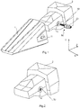
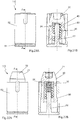
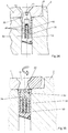
- Figure 1 shows a first embodiment of a locking device or pin 10 comprising a spring 30 and a locking element 20 before being introduced in a housing 12 of an adapter 2.
- a wear element 1, with at least one orifice 11 is also shown before being coupled on the adapter 2.
- Figure 2 shows the locking device or pin of figure 1 completely introduced in the housing 12 of the adapter 2.
- the housing 12 where the pin is to be introduced is horizontal, but it can either be vertical or longitudinal.
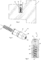
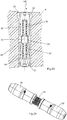
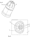
- Figures 3 to 5 show a first embodiment of a locking device or pin 10 object of the present invention that comprises a cylindrical locking element 20 with an inner cavity 24 and a thread 40 in the internal surface of the inner cavity 24.
- a spring 30 is screwed to the thread 40 of the locking element 20.
- One end of the spring 30, the base 31, is attached to the housing 12 to prevent the rotation of the spring 30 when the same is being screwed to the locking element 20; while the opposite end of the spring 30 is screwed to the locking element.
- the locking element 20 is also provided with a bearing surface 21 to contact with the corresponding bearing surface 13 of the wear element 1.
- the locking element is provided with a screwing means 22 to connect a tool that facilitates the screwing and unscrewing the locking element 20 to the spring 30.
- the spring 30 is fixed, by mechanical means or welded or adhered, to the base of the housing 12 of the adapter 2.
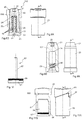
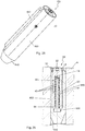
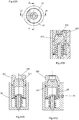
- a second embodiment of a locking device or pin 100 adds a supporting body 61 where the spring 30 is attached or fixed to prevent the spring 30 from turning when the locking element 20 is screwed or unscrewed. Moreover the supporting body 61 serves to assemble more easily the locking device in the adapter.
- the supporting body 61 is fixed or attached to the housing 12 and may have anti-rotation means to avoid its rotation inside the housing 12 of the adapter 2.
- Said supporting body 61 comprises a guide 62, which serves to maintain the spring in its axial position when the spring 30 and the locking element 20 are screwed.
- This guide 62 can be part of the supporting body 61 or may be weld or mechanically fixed on the supporting body. In some occasions the guide 62 could be a single part and would be fixed in any other element.
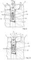
- Figures 7A-7B show the spring 30 attached to the supporting body 61 and the locking element 20 partially screwed to the spring 30 through the thread 40.
- the supporting body 61 has also screwing means 64 in its bottom surface.
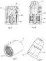
- the embodiment 110 comprises a capsule 50 formed by a body with preferably the shape of a cylindrical tube or hollow cylindrical body with two opened ends, upper end 85 and lower end 86, and a cavity 84.
- the lower end 86 will be at the bottom or base of the housing 12 whereas the upper end 85 will be at the opening of the housing, i.e., faced to the orifice 11 of the wear element 1.
- the cavity 84 of the capsule 50 is provided with a base thread 83, specifically near to the lower end 86.
- the base thread 83 is screwed to a supporting body 61 through its corresponding screw 63.
- the capsule 50 preferably has a cylindrical tube or hollow cylindrical body, the capsule 50 could be any body of revolution or any shape that avoids its rotation inside the housing 12 of the adapter.
- a groove 500 is provided inside the cavity 84 of the capsule 50 and near to the upper end 85 of the capsule 50 in which an O-ring is introduced.
- the capsule 50 together with the O-ring prevent the entry of dirt into the pin and housing, avoiding the damage of the spring 30. It is also possible and supplementary to include an O-ring in the outer surface of the locking element 20, as in the embodiment of figures 12 and 13 .
- the supporting body 61 is attached or fixed to the lower end 86 of the capsule 50.
- the supporting body 61 is preferably attached to the capsule 50 through a screw 63, although other fixing means are possible, one example could be welded.
- the supporting body 61 comprises a perpendicular guide 62 that will be introduced inside the spring 30 to maintain the spring in its axial position when the spring 30 and the locking element 20 are screwed.
- the spring 30 is attached through mechanical means or welded to the supporting body 61.
- the subassembly comprising the supporting body 61 with the spring 30 attached to it and the locking element 20, screwed to the spring 30, is introduced in the capsule 50 through its lower end 86, so that the guide 62 and the spring 30 are positioned in the inner cavity 24 on the locking element 20.
- the supporting body 61 is screwed to the capsule through the screw 63 and the base thread 83.
- the locking device is provided with a stopping means that avoids that the locking element 20 goes out from the upper end 85 of the capsule 50.
- the stopping means are stopping surfaces 82, 23.
- the locking element 20 is provided with an annular stopping surface 23 that will contact with the annular stopping surface 82 of the capsule 50 to stop the path of the locking element 20, avoiding that the locking element 20 goes out from the upper end 85.
- the locking device 110 has anti-rotation means formed as a wall 88 extending parallel to the longitudinal axis and positioned in the outer lateral surface of the capsule 50.
- the housing 12 has a corresponding wall so that if the capsule 50 rotates inside the housing 12, both walls interfere with each other blocking the capsule.
- the locking device 110 has ejection means that includes a helicoidal wall 81. This helicoidal wall has the same axis as the spring 30. So, when the locking element 20 is in its retracted position, an additional rotation forces the capsule out of the housing 12. This allows an easy extraction of the locking device from the housing 12.
- the helicoidal wall 81 is also in the outer lateral surface of the capsule 50.
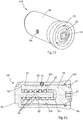
- FIG. 12 Another embodiment 120 of the locking device is the one shown in figures 12 and 13 , where the supporting body 61 with the guide 62 and the capsule 50 are built as a single element. Therefore, the capsule 50 has only one open end, the upper end 85, and the cavity 84 of the single element (supporting body+guide+capsule) is provided with an inner surface 52 on its base where the spring 30 is fixed.
- the spring 30 in order to assemble the locking element 20, the spring 30 is introduced through the upper end 85 of the capsule 50 and then it is fixed to the inner surface 52 to prevent the spring 30 from rotating when the locking element 20 is screwed on it. After that, the locking element 20 is also introduced through the upper end 85 of the capsule 50 and screwed to the spring 30 till the locking element 20 is totally introduced in the cavity 84 of the capsule 50.
- This embodiment 120 uses a bolt 70 as a stopping means.
- Said stopping element 70 has the function of preventing the locking element 20 from coming out from its path, inside the capsule 50.
- the stopping element 70 is fixed from the exterior of the capsule 50 crossing a wall of said capsule 50, so that its end is in a lateral groove foreseen in the outer lateral wall of the locking element 20, preventing and stopping the exit of the locking element 20 from the capsule 50.
- the locking device or pin 120 is introduced in the housing 12 of the adapter 2.
- the locking element 20 has a groove 500 to house a O-ring, preferably of an elastomeric material, that contributes to prevent the entry of dirt in the pin and assures the tightness between the capsule 50 and the locking element 20 so that the operation of the spring 30 in the locking device 20 is not damaged.
- a O-ring preferably of an elastomeric material
- a further embodiment 130 shows another locking device or pin 130 where the thread 40 is placed on the outer surface of the locking element 20, instead of, as in the previous embodiments, in the inner cavity 24 of the locking element 20.
- the spring 30 is attached to a supporting body 61 that is attached or fixed to a capsule 50. Said capsule 50 is screwed to the supporting body 61 through a screw 63.
- the function of the guide for maintaining the spring 30 in an axial position is made by the locking element 20 itself; the supporting body 61 is not provided with a guide 62.
- the capsule 50 or the supporting body 61 comprises anti-rotation means somewhere in their outer surface that interacts or contacts with the surfaces of the housing 12 where the pin 130 is introduced to prevent the rotation of said supporting body 61 and the capsule 50 and therefore to prevent the rotation of the spring 30.
- the thread 40 is placed in an additional element or insert 42 of the locking element 20.
- the insert 42 has a U shape, where the base of the U is fixed at the upper end of the inner cavity 24 of the locking element 20 (i.e., close to the locking end) with a screw (see figures 18 and 19A-19B , embodiment 160).
- the insert 42 has an annular shape with both ends opened.
- Figures 21A-21B and 22A-22B show a further embodiment 170 of a locking device according to the invention.
- the thread 40 is on the guide 62.
- the spring 30 is fixed in the upper end (close to the locking end) of the inner cavity 24 of the locking element 20.
- Figures 21A and 21B show the locking element in its retracted position. When the operator screws the locking element 20 out of the capsule 50 the spring 30 accompanies the locking element 20 in its movement.
- the previous embodiments (10, 100, 110, 120, 130, 160 and 170) refer to simple locking devices that only lock one side of the wear part or tooth and the adapter system, and this could cause that the tooth inclines or tilts in working conditions.
- the wear member and the adapter may be fixed through two opposite sides.
- double locking devices are used, or a simple one with a length equal to the width of the housing 12 that coincides with the width of the nose of the adapter 2, where the locking device or pin extends along all the width of the adapter. So the wear member 1 and the adapter 2 will be fixed through two opposite sides.
- the description of different embodiments of double locking devices or pins will follow.
- Figures 23 and 24 show an embodiment 140 of a locking device that comprises two opposing locking elements 20, 20'.
- This embodiment comprises a supporting body 90, with two perpendicular guides 91, 91', screwed through a thread 93 to the base thread 83 of a capsule 55.
- Capsule 55 is conceptually the union of two opposed capsules 50 as described before. Both locking elements 20, 20' are introduced at each of the opposite openings of capsule 55. Capsule 55 is as long as the housing 12 of the adapter 2 where the locking device is going to be placed.
- the supporting body 90 supports springs 30 and 30' and on each of its opposite sides one of the locking elements 20, 20' is screwed.
- the components and features of the locking device of this embodiment 140 can be the same as the ones of the previously described locking devices with only one locking element.
- Figures 25 and 26 show an embodiment 150, similar to the previous one but with only one locking element 20.
- the supporting body 90 is screwed to the capsule 800 through a thread 830.
- the supporting body 90 comprises a perpendicular guide 91 to which a spring 30 is attached.
- the lower end of the capsule 800 comprises a second bearing surface 850.
- the locking device can be enlarged until each bearing surface (21, 850) contacts with their complementary bearing surfaces on the wear part 1 (no shown in figure 26 ).
- the locking device fixes both sides of the tooth/adapter system.
- the outer surface of the capsule 800 comprises a longitudinal projection 840 that is perpendicular to the axial direction of the capsule 800 to prevent the capsule 800 from rotating inside the housing 12 of the adapter 2.
- a stopping element 70 that crosses the capsule 800 is used, as previously described in the embodiment of figures 12 and 13 .
- Figures 27 and 28 show an embodiment where two locking devices 110 are used together in the same adapter 2. These two pins 110 are as the one described for figures 8A-8B to 11A-11B . Figures 27 and 28 are an example of using two independent locking devices for fixing an adapter 2 and a wear member 1 through two opposite sides. Although the example refers to the pins 110 of figures 8A-8B to 11A-11B, any other pin object of the present invention could be used.
- the locking device is introduced in a housing 12 of the adapter 2 with the lower end 86 of a capsule 50 inside the housing 12 and the upper end 85 of the capsule 50 facing the outside, see figure 29B .
- the locking device includes anti-rotation means 88 at the outer surface of the capsule 50 to prevent the rotation of the capsule 50 inside the housing 12.
- the locking element 20 is introduced into the capsule 50 reducing the length of the pin until the bearing surface 21 is completely introduced in the capsule 50 and, consequently, in the housing 12 of the adapter.
- the locking element 20 is in what has been named the retracted position. This step has not to be done necessarily by the user as the pin may be provided to said user with the locking element 20 already screwed to the spring 30 and ready to be placed into the housing of the adapter.
- the spring 30 is attached through its base 31 to the inner surface 52 of the base of the capsule 50 to prevent the rotation of the spring 30 around its axis when the locking element 20 is screwed or unscrewed over said spring 30.
- the capsule 50 further comprises a guide 62 that is introduced in the spring 30 to prevent failures during the screwing of the spring 30 and the locking element 20.
- the wear part 1 or tooth is mounted on the adapter 2.
- the tooth 1 has an orifice 11 that, when mounted over the adapter 2, coincides with the opening of the housing 12 of the adapter 2.
- the locking element 20 is unscrewed ( figure 31 ) until the locking element 20, specifically its bearing surface 21, contacts the inclined inner surface 13 (which defines a corresponding bearing surface) of the orifice 11 in the tooth 1.
- the spring 30 works as a thread, not as an element with elastic properties.
- the locking element 20 After the locking element 20 has contacted the bearing surface 13 of the orifice 11 of the tooth 1, if the locking element 20 is further unscrewed (see figure 32 ), the locking element cannot increase further its length and the spring 30 starts to compress in the cavity 84 of the capsule 50. The unscrewing of the locking element 20 follows until the spring 30 cannot move inwards anymore because it is completely compressed inside the cavity 84 of the capsule 50. In this point, the locking device 20 is in the correct final position for working: it cannot be more unscrewed and the spring 30 is blocked. This position is the compressed position or initial locking position. Although, a readjustment of the tooth/adapter system, when it starts to work, releases the spring 30 going out from the initial locking position, and the spring will experience a little expansion. This expansion will not be enough to allow the locking element 20 to be introduced completely inside the housing 12 in an accidental external hit over the locking device. In this position the spring 30 is resiliently loaded in the cavity 84 of the capsule 50.
- An advantage of the invention is that, in spite of undesired external forces that may push the locking element 20 inwards, the locking element 20 cannot be introduced completely inside the housing anymore, because the spring 30 is in an almost completely compressed state and cannot be compressed more. Therefore, the locking element 20 cannot be moved out from the interference or blocking position, until it is screwed on the spring again.
- the tooth 1 While the tooth 1 is working the pin maintains it coupled on the adapter 2, at a certain distance A between the tooth and the adapter. After a continuous use over the time, the contact surfaces between the tooth 1 and the adapter 2 will suffer plastic deformation and inner wear, especially in the hole of the wear member and above all on the nose of the adapter. This will produce a gap that may cause an undesired play between contact surfaces of the tooth 1 and adapter 2 that may force a movement of the tooth 1 backwards, see figure 33 .
- the locking element 20 should be screwed again on the spring 30 with the help of a tool.
- the compressed part of the spring 30 starts to decompress and is screwed again to the locking element 20.
- the locking element 20 is screwed to the spring until it is introduced in the housing 12 so that the interference between the tooth 1 and the adapter 2 disappears and the tooth may be detached from the adapter.
- the locking device has anti-rotation means formed as a wall 88 extending parallel to the longitudinal axis and ejection means that includes a helicoidal wall 81 having the same axis as the spring 30. But in this case both are in the lower surface of the base of the supporting body 61.
- Figures 36A-36E are a schematic view of another example of mounting of a locking device according to the invention.
- Figure 36A shows the introduction of the locking element 20 into the capsule 50 by rotating the locking element 20 which provokes its screwing over the spring 30.
- Figure 36B shows the locking element in its fully retracted position so that the wear part 1 can be placed so that the orifice 11 is overlapped with the housing 12 of the adapter 2 (not represented in these figures) and with the locking device which is allocated in its interior.
- Figure 36C corresponds to the position in which the locking element 20 has been unscrewed from the spring 30 until the bearing surface 21 contacts the corresponding bearing surface 13 of the wear part 1. In this position, the spring is still in an unloaded state, so the position can be called the unloaded position.
- Unscrewing further the locking element 20 provokes that the part of the spring 30 outside the thread 40 compresses achieving what has been named the compressed position or the initial locking position.
- the geometry of the different components of the locking device is such that the whole spring 30 can be unscrewed from the thread 40 and remains in a compressed state.
- the operator continues rotting the locking element 20 he hears a loud "click" each time that the end of the spring passes through the end of the thread 40. This informs him that the assembly has been finished, and it also avoids that the operator overturns the spring 30.
- Figure 36E shows the case in which the relative position between the wear part 1 and the adapter 2 has changed (due to wearing and/or plastic deformation) and the locking element 20 projects outwardly a bigger amount than in the initial locking position of figure 36D .
- the spring 30 has expanded partially but the locking device maintains a proper fixing between the wear part 1 and the adapter 2. This position can be considered as the final locking position.
- both the initial locking position and the final locking position are locking positions but in the initial locking position the spring 30 is in a completely compressed state (and, in the case of figures 36A-36E , completely outside of the thread 40) whereas in the final locking position the spring 30 has expanded a certain amount in order to compensate the movement between the worn and/or deformed wear part 1 and adapter 2.
- Figure 37 shows a partial sectional view of a capsule 50 with a supporting body 61, both built as a single element, and a spring 30 fixed to it.
- the spring 30 (see also figure 38 ) has two flat surfaces 301 in the end of its outer lateral surface close to the supporting body 61 and the supporting body 61 has two corresponding flat surfaces 611 in contact with the flat surfaces 301 of the spring. These flat surfaces 301, 611 restrict the rotation of the spring 30..
- Figures 39 an 40 show a sectional view of an alternative embodiment of a locking device that includes an alternative version of the concept describes in the previous paragraph.
- the locking element 20 has an inner cavity 24 and the spring 30 is allocated in the inner cavity 24 and is fixed to the locking element 20 in the upper inner part of the inner cavity 24.
- the spring 30 has at least two flat surfaces 301 in the end of its outer lateral surface close to the locking end and the inner cavity 24 has two corresponding flat surfaces 241 in contact with the flat surfaces 301 of the spring 30.
- the embodiment of figures 39 and 40 shows also a locking device in which the guide 62 is rotatably fixed to the supporting body 61 (i.e., it is fixed in such a way that it can be rotated in respect of the supporting body).
- the locking element 20 has an access hole 205 at the locking end.
- the locking device comprises also second anti-rotation means (in the present example in form of a screw 95 and a groove 96 parallel to the longitudinal axis) able to avoid the rotation of the locking element 20 in respect of the capsule 50.
- Figures 43A-43B show an upper view and a sectional view according to line B-B, respectively, of an alternative embodiment of a locking device, in which the locking element 20 comprises a core 201 and a casing 203.
- the core 201 is rotatably mounted in the casing 203 (i.e., is mounted in such a way that can be rotated in respect of the casing).
- the casing 203 comprises the locking end and has an access hole 205 at the locking end.
- the locking device additionally comprises second anti-rotation means (in the present example, again in form of a screw 95 and a groove 96 parallel to the longitudinal axis) able to avoid the rotation of the casing 203 in respect of the capsule 50.
- the locking device preferably includes a cap 209 that closes the access hole during use in order to avoid that earth or debris goes inside the locking device.
- Figure 41 sows a perspective view of an alternative embodiment of a locking element whose bearing surface 21 of its locking end has a plurality of flat faces 211, with the shape of a frustum of a pyramid.
- one of the flat faces 211 is in contact with a corresponding flat face 131 present in the bearing surface 13 of the orifice 11 of the wear element 1. So, it is much more difficult for the locking element 20 to rotate as it has to "jump" from one flat face 211 to the next one.
- Figures 45-48 show another alternative embodiment of a locking device.
- the capsule 50 has, in its inner lateral surface, a plurality of grooves 501 parallel to each other and extending parallel to the longitudinal axis and the locking element 20 has, in its outer lateral surface, one elastic protrusion 207 allocated in one of the grooves 501.
- the elastic protrusion 207 is, for example, of an elastomeric material and can be elastically deformed so that it can be displaced from one of the grooves 501 to another one through a relative rotation movement, along the longitudinal axis, of the capsule 50 in respect of said locking element 20.
Description
- The invention relates to a locking device for securing a wear part (also named wear member) in a corresponding support (or adapter) for excavators and similar machines, where the support comprises a housing and the wear part comprises an orifice so that, in a mounted position, the housing and the orifice are at least partially overlapped, where the locking device is able to be introduced in the housing.
- The invention relates also to a wearable system comprising a wear part, a support and a locking device, where the support comprises a housing and the wear part comprises an orifice so that, in a mounted position, the housing and the orifice are at least partially overlapped, where the locking device is able to be introduced in the housing.
- The present disclosure relates additionally to a wearable system comprising a wear part, and a support, where the support comprises a housing and the wear part comprises an orifice so that, in a mounted position, the housing and the orifice are at least partially overlapped.
- The invention relates also to a process for fixing a wear part in a support with a locking device, where the support comprises a housing and the wear part comprises an orifice so that, in a mounted position, the housing and the orifice are at least partially overlapped, where the locking device is able to be introduced in the housing, the locking device comprising:
- a locking element, with a locking end, where, in the mounted position, the locking end at least partially emerges from the housing and penetrates into the orifice,
- a thread, preferably being the thread at the locking element, and
- at least one helical spring defining a longitudinal axis, where the spring is at least partially threaded in the thread, the spring being fixed in respect of the support in order to prevent its rotation in respect of the support
- Earthmoving machinery used for excavating, loading and moving materials such as rocks, sands, overburden and minerals, are usually equipped with one or more buckets or dippers attached to a mechanical arm. The bucket or dipper is provided with a blade or lip on its front edge intended to penetrate the ground and load the material. To prevent excessive wear of the lip and to increase its penetration of the ground, it is common to fit wear parts or wear members on the lip, such as teeth, adapters (tooth holders), lip protectors and side protectors.
- These wear parts or wear members are subject to wear and stress that can deteriorate them. Bucket teeth are usually the most exposed wear parts having to be frequently replaced. In addition, these machines may work in a wide range of applications, where changing the tooth design might be necessary to improve the performance of the bucket. These wear parts can be attached to other wear parts (such as a tooth attached to an adapter) and can be attached to the blade or lip (such as an adapter attached to a lip). The mechanical coupling between wear parts is usually done through a retaining element, for example a locking device or pin.
- Furthermore, the service life of a wear part coupling is also limited due to wear, fatigue, and plastic deformation.
- Two types of wear can be distinguished: the outer wear of the parts due to the flow of the excavated or loaded material, and the inner wear due to the material (dirt, fines) that is introduced between the wear parts coupling (for example between the tooth and the adapter). This material located inside the coupling between two mechanical parts increases the wear of the inner areas of such parts, due to the movement between these parts while the bucket is in operation.
- Statistically, a tooth with an average wear life performs more than 50,000 work cycles; as a result, the coupling must be designed to prevent the defects generated due to the fatigue phenomena, such as cracks, to be compatible with the plastic deformation of wear parts that happens due to the stress reactions generated to counteract the forces suffered by the wear parts, etc.
- An unwanted gap appears when there is plastic deformation and/or inner wear on the contact areas of the wear parts coupling. This gap increases the movement between the coupling's parts, increasing the risk of losing or breaking them. The gap increases over time, due to more plastic deformation and/or inner wear.
- The bearing surfaces of adapters are the most affected by the inner wear and plastic deformation because the steel used on adapters usually has a lower hardness than the steel used on teeth. The contact and friction between parts, one harder than the other, results on the deformation of the softer part. If there is fines in-between the coupling, the inner wear adds on the plastic deformation, increasing even more the gap between the contact areas of the attached parts. It is very important to reduce and avoid the movement between the attached wear parts to avoid breakages and loses of wear parts. Large earthmoving machines, especially those operating in quarries and mines, are essential for the production of the sites. Downtime on these machines due to a lost or broken part can be very costly for the customers. A lost or broken part can end up inside the crusher too, damaging and disabling this critical installation and resulting on a very expensive repair. A lost or broken wear part (also the change of the wear part when it is worn out, because it is important to change the tooth before it broke or wear out) will also require stopping the machine to assemble another part, resulting on wasted production time. For all these reasons, it is critical to make sure that wear parts do not break or fall off from the buckets or dippers.
- Nevertheless, plastic deformation and inner wear cannot be avoided. Teeth are manufactured with steels with a hardness between 450-550 HB to maximize their wear life. Adapters that have to be welded on lips cannot be produced as the same steels as teeth because it would be extremely difficult and risky to weld them on the lips; these adapters are usually manufactured with steels with lower carbon content, obtaining a hardness between 300-400 HB, resulting on an Ceq < 0,7, guaranteeing its weldability. Large earthmoving machines such as mining rope shovels, draglines and large hydraulic excavators are commonly equipped with cast lips (blades with integrated cast noses). These cast lips are usually manufactured with steels with a hardness between 200-280 HB due to the need of offering structural flexibility and high ductility to the lip, avoiding the generation of cracks on the lips. In these mining applications, plastic deformation and inner wear are very common and are the main reason of wear parts' breakages and loses.
- Other important feature of the locking device or pin is that it has to be safe and easy to assemble and disassemble allowing a quick change of the wear member. The safety of the operators is extremely important and the machine's downtime must be reduced as much as possible to maximize its operating time, so the needed time to replace teeth has to be minimized. Further, it is convenient to be able to change the wear parts in the field, in the same spot where the machine is working, without having to take the machine or bucket to the workshop to use special equipment. Conventional locking devices require a hammer to assemble and disassemble the pin. In order to make this procedure safe an easy, a hammerless locking system is desirable. This means that the pin has to be assembled and disassembled in a hammerless manner, i.e., without needing a hammer for introducing or removing the pin.
- Document
DE 202011101484 U1 describes a pin comprising a capsule with a spring within, for coupling a tooth on a tooth holder, where the pin has to be introduced in a housing in the tooth holder with the help of a special tool. This tool compresses the spring in the housing and maintains it compressed during the coupling of the tooth on the tooth holder, making the assembly difficult and unsafe. Further, the described pin makes it difficult to replace a tooth once it is worn out, as there are no means to compress the spring once it is introduced in the housing of the tooth holder. On the other hand the spring cannot be fixed to the housing, so it can be compressed undesirably during operation, and therefore the tooth could fall off while the bucket is digging or leading material. A similar device is described inUS 2010/0257759 A1 . - Document
US 5.937.550 describes a pin made up of multiple components that is introduced in a housing of a tooth holder to maintain a tooth coupled to said tooth holder. Once coupled the tooth on the tooth holder, the movements of one respect to the other due to plastic deformation are absorbed by the elastic material. The spring is used to maintain the inner components in place. The pins described in this document comprise multiple components that make the installation and maintenance of the pin more difficult, plus the probability of failure is increased. Said pins comprise, among other components, a spring, a locking element attached to a sleeve and an elastic element made of an elastic material. - Document
GB 2.151.284 - Document
US 3.030.088 describes a locking device with a locking element in which a helical spring pushes the locking element to an extended position, whereas an external force can push the locking element to a retracted position. - The aim of the present invention is to solve the problems present in the devices of the state of the art. So, an important feature of the invention is that the pin system has been designed to reduce and eliminate the gap produced by the inner wear and plastic deformation, recovering the contact between the bearing surfaces of the tooth and the adapter. This feature will allow the coupling to operate with no gap because the locking device will adapt itself to the new contact areas between the wear parts. This means that the locking device adapts itself to the new contact areas automatically, without the need of having an operator stopping the machine to retighten and reposition the locking system. This offers greater reliability, allowing an optimum fit between all parts. Additionally, the present invention also intends to obtain a locking device or pin that is safe and easy to assemble and disassemble allowing a quick change out of the wear parts through a hammerless-style locking device. In addition, it targets to have less components (reducing the cost and the risk of failure).
- This purpose is obtained by the means of a locking, as defined in
claim 1, for securing a wear member on a support for excavators and similar machines which comprises: - a locking element, with a locking end,
- a thread,
- at least one helical spring defining a longitudinal axis, where the spring is at least partially threaded in the thread, and
- screwing means for screwing and unscrewing the locking element in or from said spring (30).
- According to the invention, the support comprises a housing and the wear part comprises an orifice so that, in a mounted position, the housing and the orifice are at least partially overlapped, where the locking device is able to be introduced in the housing, where, in the mounted position, the locking end at least partially emerges from the housing and penetrates into the orifice.
- In this way, the locking device according to the invention allows an easy assembly and disassembly, without the need of a hammer and with a reduced number of components. The helical spring takes benefit of its helical form and is directly threaded on a thread, allowing the axial displacement of the spring (which will force also the movement of the locking element along said axis), which allows a plurality of advantages as will be shown below.
- Preferably the length of the locking element and the spring in an at least partially threaded position in the thread is smaller or equal than the length of the housing. So, the operator will introduce the locking element in this at least partially threaded position in the housing and, as the locking element will not protrude outside from the housing, the operator will be able to put the wear part over the support without any opposing force exerted by the locking element. Most preferably, the length of the locking element and the spring in a completely threaded position in the thread is smaller or equal than the length of the housing.
- The locking element and the spring are threaded together, so that the spring works both as a screw and as a spring, allowing the locking element to resize itself, varying its length, depending of the wearing conditions between the wear member and the adapter. This set up also prevents the locking device from unintentionally unblocking itself during operation due to an undesirable compression of the spring.
- In order to be able to work both as a screw and as a spring, it is necessary that, if the spring is at least partially unthreaded of the thread, the unthreaded part of the spring has its unthreaded turns free so that the unthreaded part is able to change its length. So, the threaded part works like a thread whereas the unthreaded part works simultaneously like a spring.
- The coupling between the wear member or tooth, usually a "female part" in the sense that it has a hole in which a nose from the adapter is introduced, and the adapter or tooth holder, usually a "male part" in the sense that it has a nose that is introduced inside a hole present in the wear member, as well as the uncoupling, are performed in a simple way, from the outside, without the need to use special tools or apply strong forces on the locking device, which can be dangerous. At the same time it provides solid and reliable coupling while working due to the fact that the locking device or pin can absorb slight movements of the wear member over the adapter and auto-adjusts its length.
- Inverse systems are also possible, where the male part is part of the tooth and the female part is part of the adapter.
- The locking device explained also would be used in three part systems. These three part system consist of a point, an intermediate part and a weld or cast adapter. The cast or weld adapter is provided with the male part, the intermediate part is provided with a female part on the back and with a male part on the front and the point is provided with another female part.
- To secure the wear member to an adapter, the locking device is first introduced in a housing of the adapter with the locking end facing the outside of the adapter and the base of the spring inside the housing. Although it is preferably that the locking device is introduced into a housing of the adapter, it will also be feasible introduced into a housing of the wear member.
- In one alternative the spring is in a fixed position and the thread is moved by the action of the operator so that the spring screws or unscrews from the thread, whereas in another alternative what is fixed is the thread and the spring is moved by the action of the operator. As will be seen later, both alternatives allow the design of advantageous solutions. In any case the screwing or unscrewing of the spring from the thread tends to move the locking element in an axial direction.
- In one disclosure the spring is directly fixed to said support. In fact, it must be possible to have a relative rotation between the spring and the thread so that it can be in a more or less screwed position. As it will be seen later, the thread may be positioned in a plurality of components or places of the locking device, each of them allowing a different fixing of the spring so that it can be screwed and unscrewed from the thread. In this alternative, the spring is fixed, for example, to the housing by welding or using means or interconnections that are included in the housing, in order to prevent the rotation of the spring around its axis when it is screwed or unscrewed to the thread. With this disclosure, the locking device has a minimum of parts.
- In another disclosure the locking device comprises, additionally, a supporting body, able to be allocated in the bottom of the housing, and the spring is fixed in respect of the supporting body in order to prevent its rotation in respect of the supporting body. This alternative allows an easier way of fixing the spring in respect of the thread, and avoids the need of intervention in the adapter.
- Advantageously the locking end comprises a bearing surface that form a non-zero angle with said longitudinal axis, where, in said mounted position, the bearing surface is in contact with a corresponding bearing surface present in the orifice. As explained above, one aim of the present invention is to obtain a reliable assembly between wear parts (especially between teeth and adapters, and between adapters and cast noses) cancelling the negative effects of the gap generated by plastic deformation and/or the wear in-between the coupling, plus compensating the gaps due to the manufacturing tolerances between wear parts. The locking device or pin object of the present invention, intends to correct the misalignments between the fitting or coupling of wear parts produced by plastic deformation, inner wear and also due to manufacturing tolerances. With this preferred solution this problem is solved, as the locking device assures always a full contact between both bearing surfaces and presses constantly the tooth against the adapter, also if the wearing of these parts changes their geometries.
- The bearing surface of the locking element is preferably complementary in shape with the corresponding bearing surface of the orifice so that a better contact between both is achieved. In this sense the locking end of the locking element has preferably a truncated cone shape. A preferred embodiment has a locking element with a locking end which bearing surface shaped as a truncated cone and an orifice with a bearing surface which is a flat surface, where the angle of the truncated cone and the angle between the flat surface and the axis of the cone (in a mounted position) are the same, so that the contact between the truncated cone and the flat surface is along a generatrix of the truncated cone.
- Preferably the supporting body comprises a guide or shaft introduced in the spring. This allows guiding the spring, maintaining it in an axial position, avoiding axial movements and giving the spring more stability.
- Advantageously the supporting body comprises lateral walls defining a capsule, able to accommodate at least partially said locking element. So, the supporting body is like a tube with a closed end (the base of the supporting body) and lateral walls that define a capsule where the locking element can be allocated. Another preferable solution is when the locking device comprises a capsule, able to accommodate at least partially the locking element, where the supporting body is fixed to one end of the capsule. In both cases, the capsule isolates the spring and the thread from debris, powder, etc. In the first case, the supporting body and the capsule are formed as one single part, reducing the quantity of parts of the locking device. In the second alternative, it is easier to fix the spring to the supporting body, as it can be done before fixing the capsule to the supporting body. Additionally, it is easier to mechanize both parts as separate parts and also this second alternative could made both parts of different materials.
- Preferably the capsule comprises anti-rotation means able to avoid the rotation of the supporting body in respect of the housing in the mounted position. This prevents that the whole locking device rotates respect the housing in the adapter when the spring is screwed or unscrewed from the thread. Advantageously the anti-rotation means comprises a wall extending parallel to the longitudinal axis. It can be positioned, for example, on the outer lateral surface of the capsule or on the lower surface of the base of the supporting body. This last alternative allows reducing the overall diameter of the locking device.
- In another disclosure, the locking device comprises ejection means that includes a helicoidal wall, which is coaxial with the longitudinal axis. It can also be positioned on the outer lateral surface of the capsule or on the lower surface of the base of the supporting body.
- The thread can be allocated in different parts of the locking device. One preferred alternative is that the thread is on the locking element. In this case there are two possible alternatives: the thread can be in the outer surface of the locking element (so that the spring screws over the locking element) or it can be in the inner surface of an inner cavity foreseen in the locking element, the inner cavity being axially oriented and opened at the end opposite to the locking end. In this second alternative, the spring will be allocated at least partially inside the inner cavity and the thread will be over the spring. Another preferred alternative is to include the thread on the guide (on the external surface from the guide). In this case, the spring will screw over the thread.
- In another disclosure, the locking device has stopping means able to avoid that the locking element can go out completely from the capsule, so avoiding the possible loss of the locking element during the assembly or during operation. Preferably the stopping means comprises a first stopping surface in the outer surface of the locking element and a second stopping surface in the inner surface of the capsule, so that the first stopping surface is longer in a radial direction respect of the longitudinal axis than the remaining part of said outer surface of the locking element and so that the second stopping surface protrudes out of the remaining part of the inner surface of the capsule. Both the first stopping surface and the second stopping surface are preferably annular surfaces, so that they offer a big contact surface between them. Another possible alternative of the stopping means can include a pin (preferably a screw) inserted in the lateral wall of the capsule so that its end projects in the interior of the cavity defined by the capsule and in the interior of a lateral groove foreseen in the lateral surface of the locking element.
- In another disclosure, the locking element has an annular groove and a tightening ring inserted in it. So, the interior of the capsule can be better isolated from the debris, powder, etc.
- In another disclosure, the locking device comprises a second locking element, opposed to the locking element, and a second spring, opposed to the spring. This allows a symmetrical fixing of the wear part at two opposite sides thereof. As it will be shown below, this can be achieved in several ways. In one case, the housing of the adapter is a through hole and the capsule or the supporting body comprises a second bearing surface, so that both bearing surfaces can project outside of the housing at both ends of it. Other possible alternatives are providing a supporting body with two opposed capsules, each of them including a locking member according to the invention. A third possible solution could be, for example, simply using two locking devices according to the invention in two opposed housings, which may be internally connected or not. If the locking device only locks one side of the wear part and adapter system, this might cause that the wear part inclines or tilts in working conditions. To obtain a stable system it is preferably to have a double locking device. The double locking device extends along all the width of the adapter, improving the stability of the system. Furthermore the diameter of the locking device could be smaller and the strength of the nose of the adapter is better.
- In another disclosure, the screwing means are in the locking element. Usually the operator will screw and unscrew the thread from the spring by rotating the locking element. Therefore, the locking element has preferably screwing means that facilitates this operation. The screwing means is preferably in the locking end Alternatively, the screwing means are in said guide. A preferred solution including this alternative and the corresponding advantages are explained later on.
- In another disclosure, the screwing means comprise a hole, coaxial with the longitudinal axis, which has not cylindrical symmetry according to the longitudinal axis. So, any tool with an outer lateral surface corresponding to the inner lateral surface of the hole will provoke the rotation of the hole when rotated along the longitudinal axis. The hole may be, for example, a hexagonal hole oriented towards the outside so that the operator can easily introduce the corresponding tool in it and rotate the locking element.
- Preferably the locking element comprises and internal insert disposed in the inner cavity of the locking element, where the thread is in the insert. This has several advantages:
- the locking element and the insert may be of different materials, if required,
- the insert may be threaded before being inserted into the inner cavity of the locking element. This allows using better machining techniques that, for example, allows increasing the radius between the thread base and the lateral internal wall of the insert, increasing the mechanical properties of the thread.
- In one disclosure, the insert is a generally U shaped part, where the base of the U is oriented towards the end of the inner cavity of the locking element and the inner surfaces of the legs of the U comprise the thread. In another preferred alternative the insert is a ring with both ends opened and the thread is in the inner annular wall of the ring.
- Preferably the thread is shorter than the spring. In fact, only the last turns of the thread (in fact only the last turn of the thread) will be subjected to mechanical forces. So it is possible to design a thread with only one turn o two turns.
- As has been explained before, the locking device may have a supporting body. The supporting body has a base with an upper surface, oriented towards the locking element and a lower surface, opposite to the upper surface. In general, the thread has an upper end, close to the locking end, and a lower end, opposed to the upper end. In this case, a preferred solution is obtained when, in an initial locking position, the space between the lower end of the thread and the upper surface of the base of the supporting body is such that the spring is completely out of the thread. In fact, when the designer is designing the locking device, he will define an initial locking position taking into account the specific use foreseen for the locking device (the geometry of the wearable system, formed by a wear part and a support, where it will be used, the working conditions foreseen for the wearable system, the wear foreseen for the wearable system, etc.). The locking position may change during use (for example due to wear, as commented before) but the designer will always define an initial locking position and will design the different parts of the locking device taking into account this initial locking position. Therefore, the initial locking position is in fact a specific feature of the locking device. As will be explained later, this preferred solution optimizes the length of the spring (using the shortest spring), which also allows to minimize the size of the inner cavity of the locking element, i.e., the space between the lower end of the thread and the upper surface of the base of the supporting body (minimizing the size of the whole locking device and rigidifying the locking end) and "informs" the operator that the assembly has been finished with a loud "click".
- Advantageously the spring has at least one flat surface in the end of its outer lateral surface close to the supporting body and the supporting body has a corresponding flat surface in contact with the flat surface of the spring. Alternatively, the locking element has an inner cavity and the spring is allocated in the inner cavity and is fixed to the locking element, where the spring has at least one flat surface in the end of its outer lateral surface close to the locking end and the inner cavity has a corresponding flat surface in contact with the flat surface of the spring. Both alternatives are an easy way of fixing the spring to the locking device, as will be explained with further detail later on.
- One possible problem may appear if the locking element rotates during use, specifically an accidental or not desired rotation of the locking element due to the friction with stones or ground, loosening the coupling between the wear part and the support. In order to avoid this problem, several advantageous solutions are possible:
- the bearing surface of the locking end has at least one flat face, where, in the mounted position, the flat face of the bearing surface of said locking end is in contact with a corresponding flat face present in the bearing surface of the orifice, and preferably the locking end has a plurality of these flat faces. As a preferred solution, the locking end has the shape of a frustum of a pyramid.
- the guide is rotatably fixed to the supporting body (61), where the locking element has an access hole at said locking end, and preferably the locking device comprises second anti-rotation means able to avoid the rotation of the locking element in respect of the capsule.
- the locking element comprises a core and a casing, the core being rotatably mounted in the casing, where the casing comprises the locking end and has an access hole at the locking end, and preferably the locking device comprises second anti-rotation means able to avoid the rotation of the casing in respect of the capsule.
- the capsule has, in its inner lateral surface, a plurality of grooves parallel to each other and extending parallel to the longitudinal axis and the locking element has, in its outer lateral surface, at least one elastic protrusion allocated in one of the grooves, the elastic protrusion being able to be elastically deformed so that it can be displaced from one of the grooves to another one through a relative rotation movement, along the longitudinal axis, of the capsule in respect of the locking element.
- Another object of the invention is a wearable system, as defined in claim 18, comprising a wear part, a support and a locking device, where the support comprises a housing and the wear part comprises an orifice so that, in a mounted position, the housing and the orifice are at least partially overlapped, where the locking device is able to be introduced in the housing wherein the locking device comprises:
- a locking element, with a locking end, where, in the mounted position, the locking end at least partially emerges from the housing and penetrates into the orifice,
- at least one helical spring defining a longitudinal axis,
- a thread, preferably at the locking element, where the spring is at least partially threaded in the thread, the spring being fixed in respect of the support in order to prevent its rotation in respect of the support, and
- screwing means for screwing and unscrewing the locking element in or from the spring.
- The housing of the wearable system may be a blind hole. In this case, one disclosure is obtained when, in an initial locking position, the space between the lower end of the thread and the base of the housing is such that the spring is completely out of the thread, with the advantages explained above. As can be seen, in this case the base of the blind hole that conforms the housing plays the role of the base of the supporting body.
- Another disclosure is as wearable system comprising a wear part, and a support, where the support comprises a housing and the wear part comprises an orifice so that, in a mounted position, the housing and the orifice are at least partially overlapped, characterized in that it comprises a locking device according to invention, where the locking device is able to be introduced in the housing and, in the mounted position, the locking end at least partially emerges from the housing and penetrates into the orifice.
- Preferably the spring has a length such that, in an initial locking position, the spring is completely out of the thread.
- Another object of the invention is a process, as defined in claim 16, for fixing a wear part in a support with a locking device, where the support comprises a housing and the wear part comprises an orifice so that, in a mounted position, the housing and the orifice are at least partially overlapped, where the locking device is able to be introduced in the housing, the locking device comprising:
- a locking element, with a locking end, where, in the mounted position, the locking end at least partially emerges from the housing and penetrates into the orifice,
- a thread, preferably being the thread at the locking element, and
- at least one helical spring defining a longitudinal axis, where the spring is at least partially threaded in the thread, the spring being fixed in respect of the support in order to prevent its rotation in respect of the support,
- insertion of the locking device in the housing,
- positioning of the wear part over the support in the mounted position, so that the housing and the orifice are at least partially overlapped,
- unscrewing the locking element from the spring until the locking end penetrates into the orifice and contacts the wear part, (preferably the locking element has a bearing surface and the wear part has also a corresponding bearing surface and the contact between both elements is through their bearing surfaces),
- further unscrewing the locking element from the spring until the spring is in a compressed state. This compressed state will force the locking element always in the axial direction out of the housing, i.e., towards the wear part. So, any change in the geometry of the wear part, the adapter and/or the locking device itself will be compensated by the biasing force of the spring, which will maintain the different parts in their assembled positions.
- The locking device is preferably a locking device according to any one of
claims 1 to 15. - In one disclosure, the step of further unscrewing the locking element from the spring is done until the spring is in a completely compressed state.
- In another disclosure, the step of further unscrewing the locking element from the spring is done until the spring is completely out of the thread. At this moment, the operator will hear a loud "click" that will inform him that the unscrewing step has finished, so avoiding that the spring is overturned or avoiding that it is not completely compressed.
in another disclosure, the process comprises a step previous to the insertion step consisting in screwing the locking element on the spring. This allows to form a mounted assembly which is easy to handle and includes all the elements of the locking device. This step may be done by the operator or, preferably, is done by the manufacturer of the locking device, so that the locking device is delivered as said mounted assembly. - Preferably the length of the locking element and the spring in an at least partially threaded position in the thread is smaller or equal than the length of the housing. Most preferably, the length of the locking element and the spring in a completely threaded position in the thread is smaller or equal than the length of the housing.
- The step to screw the locking element on the spring may be done when the spring is already fixed in the housing or before fixing the spring in the housing.
- An advantage of the invention is that in front of undesired external forces that may bring the locking element inwards in accidental way, the locking element cannot be introduced completely inside the housing anymore, because the locking element does not have enough space in the housing to be completely introduced, as the space has been occupied by the compressed part of the spring that is not screwed to the locking element. Therefore, the locking element may not be pushed out from the interference or locking position until it is screwed on the spring again.
- The only way to disassemble the tooth from the adapter is to screw the locking element over the spring completely again. This has the advantage of preventing the loose of the teeth in accidental way, as may happen in the device described in prior art document
DE202011101484A1 . - To better understand the object of the present application, figures in which several practical embodiments are depicted schematically and only by way of non-limiting example are attached.
-
Figure 1 - Exploded view of a locking device (or pin) object of the present invention with a wear member (a tooth) and an adapter where the wear member is mounted. -
Figure 2 - Nose of an adapter with the locking device mounted in the housing. -
Figure 3 - A sectional view of a nose of an adapter with a first embodiment of a locking device according to the invention within the housing. -
Figure 4 - An exploded view of the locking device offigure 3 . -
Figure 5 - A sectional view of the locking device offigures 3 and 4 . -
Figures 6A-6D - A front view, upper view, lower view and sectional view according to line A-A, respectively, of an alternative embodiment of a locking device according to the invention with a supporting body. -
Figures 7A-7B - A front view and a sectional view according to line A-A, respectively, of the locking device offigures 6A-6D in an extended position. -
Figures 8A-8B - A front view and a sectional view according to line A-A, respectively, of an alternative embodiment of a locking device with a supporting body structure and a capsule or sleeve. -
Figures 9A-9B - A front view and a sectional view according to line A-A, respectively, of the locking element of the locking device offigures 8A-8B . -
Figure 10 - A view of the supporting body of the locking device infigures 8A-8B . -
Figures 11A-11B - A front view and a sectional view according to line A-A, respectively, of the capsule or sleeve of the locking device infigures 8A-8B . -
Figure 12 - A perspective view of an alternative embodiment of a locking device, where the supporting body and the capsule are the same element. -
Figure 13 - A sectional view of the locking device offigure 12 . -
Figure 14 - A front view of an embodiment of a locking element with the thread on its outside surface -
Figure 15 - A front view of the locking element offigure 14 mounted on the supporting body and with the spring screwed on its thread. -
Figure 16 - A sectional view of a locking device including the locking element offigures 14 and 15 . -
Figure 17 - A perspective view of an insert. -
Figure 18 - An exploded view on the insert offigure 17 and a locking element. -
Figures 19A-19B - A front view and a sectional view according to line A-A, respectively, of the locking element with the insert offigures 17 and 18 . -
Figures 20A-20C - An upper view, a sectional view according to line A-A and perspective view, respectively, of another insert according to the invention. -
Figures 21A-21B - A front view and a sectional view according to line A-A, respectively, of a locking device with the locking element in retracted position. -
Figures 22A-22B - A front view and a sectional view according to line A-A, respectively, of the locking device offigures 21A-21B with the locking element in compressed or locking position. -
Figures 23 - A partial sectional view of a locking device with two locking elements in a supporting body with two capsules or sleeves, mounted in an adapter. -
Figure 24 - A perspective view of the locking device offigure 23 . -
Figure 25 - A perspective view of an alternative embodiment of a locking device. -
Figure 26 - A partial sectional view of the locking device offigure 25 installed in an adapter. -
Figure 27 - A front view of two locking devices, opposed to each other. -
Figure 28 - A partial perspective view of an adapter with two locking devices opposed to each other. -
Figure 29A-29B - A front view and a sectional view according to line B-B, respectively, of an adapter with two locking devices opposed to each other as shown infigure 28 . -
Figure 30 - A sectional view of a wear member mounted or coupled to an adapter, specifically a tooth on a tooth holder, before the locking element is extended. -
Figure 31 - A partial sectional view of the locking element being unscrewed when the tooth and tooth holder have been coupled. -
Figure 32 - A partial sectional view of the locking element being further unscrewed until the spring is compressed into the capsule, when the tooth and tooth holder have been coupled. -
Figure 33 - A partial sectional view of the locking element when the tooth moves backwards during use when coupled on to the tooth holder. -
Figure 34 - A partial sectional view of the locking element when the tooth has moved backwards during use and the locking element has been repositioned. -
Figure 35 - A partial sectional view of the locking element being screwed to uncouple the tooth and tooth holder. -
Figures 36A-36E - A schematic sectional view of the assembly sequence in an alternative embodiment of the invention. -
Figure 37 - A partial sectional view of a capsule and a spring fixed to it. -
Figure 38 - A perspective view of the spring offigure 37 . -
Figure 39 - A sectional view of an alternative embodiment of a locking device. -
Figure 40 - A sectional view of the locking device offigure 39 in extended position. -
Figure 41 - A perspective view of an alternative embodiment of a locking element. -
Figure 42 - An upper partial view of the locking element offigure 41 and theorifice 11 of a wear element. -
Figures 43A-43B - An upper view and a sectional view according to line B-B, respectively, of an alternative embodiment of a locking device. -
Figures 44A-44B - A sectional view according to line A-A and according to line B-B, respectively, of the locking device offigures 43A-43B in extended position. -
Figure 45 - A sectional view of an alternative embodiment of a locking device. -
Figure 46 - A sectional view of the locking device offigure 45 in extended position. -
Figure 47 - A perspective view of the capsule of the locking device offigure 45 . -
Figure 48 - A perspective view of the locking element of the locking device offigure 45 . -
Figure 1 shows a first embodiment of a locking device or pin 10 comprising aspring 30 and a lockingelement 20 before being introduced in ahousing 12 of anadapter 2. Awear element 1, with at least oneorifice 11 is also shown before being coupled on theadapter 2.Figure 2 shows the locking device or pin offigure 1 completely introduced in thehousing 12 of theadapter 2. Infigure 1 , thehousing 12 where the pin is to be introduced is horizontal, but it can either be vertical or longitudinal. -
Figures 3 to 5 show a first embodiment of a locking device or pin 10 object of the present invention that comprises acylindrical locking element 20 with aninner cavity 24 and athread 40 in the internal surface of theinner cavity 24. Aspring 30 is screwed to thethread 40 of the lockingelement 20. One end of thespring 30, thebase 31, is attached to thehousing 12 to prevent the rotation of thespring 30 when the same is being screwed to the lockingelement 20; while the opposite end of thespring 30 is screwed to the locking element. - The locking
element 20 is also provided with a bearingsurface 21 to contact with the corresponding bearingsurface 13 of thewear element 1. The locking element is provided with a screwingmeans 22 to connect a tool that facilitates the screwing and unscrewing the lockingelement 20 to thespring 30. - In this first embodiment the
spring 30 is fixed, by mechanical means or welded or adhered, to the base of thehousing 12 of theadapter 2. - A second embodiment of a locking device or
pin 100, seefigures 6A-6D and 7A-7B , adds a supportingbody 61 where thespring 30 is attached or fixed to prevent thespring 30 from turning when the lockingelement 20 is screwed or unscrewed. Moreover the supportingbody 61 serves to assemble more easily the locking device in the adapter. - Furthermore, the supporting
body 61 is fixed or attached to thehousing 12 and may have anti-rotation means to avoid its rotation inside thehousing 12 of theadapter 2. Said supportingbody 61 comprises aguide 62, which serves to maintain the spring in its axial position when thespring 30 and the lockingelement 20 are screwed. Thisguide 62 can be part of the supportingbody 61 or may be weld or mechanically fixed on the supporting body. In some occasions theguide 62 could be a single part and would be fixed in any other element. -
Figures 7A-7B show thespring 30 attached to the supportingbody 61 and the lockingelement 20 partially screwed to thespring 30 through thethread 40. The supportingbody 61 has also screwingmeans 64 in its bottom surface. - To further improve the locking device, in
figures 8A-8B to 11A-11B analternative embodiment 110 is shown. Theembodiment 110 comprises acapsule 50 formed by a body with preferably the shape of a cylindrical tube or hollow cylindrical body with two opened ends,upper end 85 andlower end 86, and acavity 84. In the mounted position, thelower end 86 will be at the bottom or base of thehousing 12 whereas theupper end 85 will be at the opening of the housing, i.e., faced to theorifice 11 of thewear element 1. Thecavity 84 of thecapsule 50 is provided with abase thread 83, specifically near to thelower end 86. Thebase thread 83 is screwed to a supportingbody 61 through its correspondingscrew 63. Although, thecapsule 50 preferably has a cylindrical tube or hollow cylindrical body, thecapsule 50 could be any body of revolution or any shape that avoids its rotation inside thehousing 12 of the adapter. - Moreover, inside the
cavity 84 of thecapsule 50 and near to theupper end 85 of the capsule 50 agroove 500 is provided in which an O-ring is introduced. Thecapsule 50 together with the O-ring prevent the entry of dirt into the pin and housing, avoiding the damage of thespring 30. It is also possible and supplementary to include an O-ring in the outer surface of the lockingelement 20, as in the embodiment offigures 12 and 13 . - In this
locking device 110, the supportingbody 61 is attached or fixed to thelower end 86 of thecapsule 50. The supportingbody 61 is preferably attached to thecapsule 50 through ascrew 63, although other fixing means are possible, one example could be welded. The supportingbody 61 comprises aperpendicular guide 62 that will be introduced inside thespring 30 to maintain the spring in its axial position when thespring 30 and the lockingelement 20 are screwed. Thespring 30 is attached through mechanical means or welded to the supportingbody 61. - To assemble the locking device, the subassembly comprising the supporting
body 61 with thespring 30 attached to it and the lockingelement 20, screwed to thespring 30, is introduced in thecapsule 50 through itslower end 86, so that theguide 62 and thespring 30 are positioned in theinner cavity 24 on the lockingelement 20. After that the supportingbody 61 is screwed to the capsule through thescrew 63 and thebase thread 83. - The locking device is provided with a stopping means that avoids that the locking
element 20 goes out from theupper end 85 of thecapsule 50. In this embodiment the stopping means are stoppingsurfaces element 20 is provided with an annular stoppingsurface 23 that will contact with the annular stoppingsurface 82 of thecapsule 50 to stop the path of the lockingelement 20, avoiding that the lockingelement 20 goes out from theupper end 85. - The
locking device 110 has anti-rotation means formed as awall 88 extending parallel to the longitudinal axis and positioned in the outer lateral surface of thecapsule 50. Thehousing 12 has a corresponding wall so that if thecapsule 50 rotates inside thehousing 12, both walls interfere with each other blocking the capsule. Additionally, thelocking device 110 has ejection means that includes ahelicoidal wall 81. This helicoidal wall has the same axis as thespring 30. So, when the lockingelement 20 is in its retracted position, an additional rotation forces the capsule out of thehousing 12. This allows an easy extraction of the locking device from thehousing 12. In this embodiment, thehelicoidal wall 81 is also in the outer lateral surface of thecapsule 50. - Another
embodiment 120 of the locking device is the one shown infigures 12 and 13 , where the supportingbody 61 with theguide 62 and thecapsule 50 are built as a single element. Therefore, thecapsule 50 has only one open end, theupper end 85, and thecavity 84 of the single element (supporting body+guide+capsule) is provided with aninner surface 52 on its base where thespring 30 is fixed. - In this
embodiment 120, in order to assemble the lockingelement 20, thespring 30 is introduced through theupper end 85 of thecapsule 50 and then it is fixed to theinner surface 52 to prevent thespring 30 from rotating when the lockingelement 20 is screwed on it. After that, the lockingelement 20 is also introduced through theupper end 85 of thecapsule 50 and screwed to thespring 30 till the lockingelement 20 is totally introduced in thecavity 84 of thecapsule 50. - This
embodiment 120 uses abolt 70 as a stopping means. Said stoppingelement 70 has the function of preventing the lockingelement 20 from coming out from its path, inside thecapsule 50. Once the lockingelement 20 and thespring 30 have been assembled inside thecapsule 50, the stoppingelement 70 is fixed from the exterior of thecapsule 50 crossing a wall of saidcapsule 50, so that its end is in a lateral groove foreseen in the outer lateral wall of the lockingelement 20, preventing and stopping the exit of the lockingelement 20 from thecapsule 50. Afterwards the locking device or pin 120 is introduced in thehousing 12 of theadapter 2. - The locking
element 20 has agroove 500 to house a O-ring, preferably of an elastomeric material, that contributes to prevent the entry of dirt in the pin and assures the tightness between thecapsule 50 and the lockingelement 20 so that the operation of thespring 30 in thelocking device 20 is not damaged. - A
further embodiment 130, seefigures 14 to 16 , shows another locking device or pin 130 where thethread 40 is placed on the outer surface of the lockingelement 20, instead of, as in the previous embodiments, in theinner cavity 24 of the lockingelement 20. Thespring 30 is attached to a supportingbody 61 that is attached or fixed to acapsule 50. Saidcapsule 50 is screwed to the supportingbody 61 through ascrew 63. In thisembodiment 130, the function of the guide for maintaining thespring 30 in an axial position is made by the lockingelement 20 itself; the supportingbody 61 is not provided with aguide 62. - In this
embodiment 130, as in the previous one, in order to prevent the assembly formed by thespring 30 and thecapsule 50 from rotating when the lockingelement 20 is screwed on it, thecapsule 50 or the supportingbody 61 comprises anti-rotation means somewhere in their outer surface that interacts or contacts with the surfaces of thehousing 12 where thepin 130 is introduced to prevent the rotation of said supportingbody 61 and thecapsule 50 and therefore to prevent the rotation of thespring 30. - In other embodiments, see
figures 17 to 20A-20C , thethread 40 is placed in an additional element or insert 42 of the lockingelement 20. Infigure 17 theinsert 42 has a U shape, where the base of the U is fixed at the upper end of theinner cavity 24 of the locking element 20 (i.e., close to the locking end) with a screw (seefigures 18 and 19A-19B , embodiment 160). Infigures 20A-20C theinsert 42 has an annular shape with both ends opened. -
Figures 21A-21B and 22A-22B show afurther embodiment 170 of a locking device according to the invention. In this example thethread 40 is on theguide 62. Thespring 30 is fixed in the upper end (close to the locking end) of theinner cavity 24 of the lockingelement 20.Figures 21A and 21B show the locking element in its retracted position. When the operator screws the lockingelement 20 out of thecapsule 50 thespring 30 accompanies the lockingelement 20 in its movement. When the bearingsurface 21 of the lockingelement 20 enters into contact with the corresponding bearingsurface 13 of the wear part 1 (not shown in this figures), the lockingelement 20 cannot continue its movement out of thecapsule 50, but the spring can continue unscrewing from thethread 40, so that it compresses in the upper end of theinner cavity 24 of the lockingelement 20, as shown infigures 22A and 22B . - The previous embodiments (10, 100, 110, 120, 130, 160 and 170) refer to simple locking devices that only lock one side of the wear part or tooth and the adapter system, and this could cause that the tooth inclines or tilts in working conditions. In order to improve the stability of the system, the wear member and the adapter may be fixed through two opposite sides. To obtain this stability double locking devices are used, or a simple one with a length equal to the width of the
housing 12 that coincides with the width of the nose of theadapter 2, where the locking device or pin extends along all the width of the adapter. So thewear member 1 and theadapter 2 will be fixed through two opposite sides. The description of different embodiments of double locking devices or pins will follow. -
Figures 23 and 24 show anembodiment 140 of a locking device that comprises two opposinglocking elements 20, 20'. This embodiment comprises a supportingbody 90, with twoperpendicular guides 91, 91', screwed through athread 93 to thebase thread 83 of acapsule 55.Capsule 55 is conceptually the union of twoopposed capsules 50 as described before. Both lockingelements 20, 20' are introduced at each of the opposite openings ofcapsule 55.Capsule 55 is as long as thehousing 12 of theadapter 2 where the locking device is going to be placed. The supportingbody 90 supports springs 30 and 30' and on each of its opposite sides one of the lockingelements 20, 20' is screwed. The components and features of the locking device of thisembodiment 140 can be the same as the ones of the previously described locking devices with only one locking element. -
Figures 25 and 26 show anembodiment 150, similar to the previous one but with only one lockingelement 20. In this case, the supportingbody 90 is screwed to thecapsule 800 through athread 830. The supportingbody 90 comprises aperpendicular guide 91 to which aspring 30 is attached. The lower end of thecapsule 800 comprises asecond bearing surface 850. When a corresponding connected to the screwingmeans 22 is operated the whole length of the locking device is modified due to the fact that the lockingelement 20 and thesecond bearing surface 850 of thecapsule 800 move in opposite directions. So, the locking device can be enlarged until each bearing surface (21, 850) contacts with their complementary bearing surfaces on the wear part 1 (no shown infigure 26 ). As a consequence, in thisembodiment 150, the locking device fixes both sides of the tooth/adapter system. - The outer surface of the
capsule 800 comprises alongitudinal projection 840 that is perpendicular to the axial direction of thecapsule 800 to prevent thecapsule 800 from rotating inside thehousing 12 of theadapter 2. To prevent thelocking element 20 from going out of thecapsule 800, a stoppingelement 70 that crosses thecapsule 800 is used, as previously described in the embodiment offigures 12 and 13 . -
Figures 27 and 28 show an embodiment where twolocking devices 110 are used together in thesame adapter 2. These twopins 110 are as the one described forfigures 8A-8B to 11A-11B .Figures 27 and 28 are an example of using two independent locking devices for fixing anadapter 2 and awear member 1 through two opposite sides. Although the example refers to thepins 110 offigures 8A-8B to 11A-11B, any other pin object of the present invention could be used. The use of two independent pins is useful when it is desired to have a more stable system, fixing the two sides of the wear element and adapter system, but there is no space between adapters to introduce a larger locking device such asembodiments housing 12 with two locking elements (or at least with two bearing surfaces) as the ones described infigures 23 to 26 . - The installation and working sequence of the locking device 120 (
figures 12 and 13 ) will now be described with reference tofigures 29A-29B to 35 , for securing awear member 1 or tooth to anadapter 2. Although the description refers to thepin 120 offigures 12 and 13 , the same can be applied to the rest of the embodiments described above as the basic principles of the invention apply to all of the pins. The explanation will be made referring only to one of the pins but, the explanation may be extended to a coupling with only one pin in ahousing 12 of anadapter 2, with two independent pins in a housing ofadapter 2, with one pin with two locking elements or two bearing surfaces, or with one pin made up of two independent pins joined together. The pin can be shorter that thehousing 12 or have the same length as thehousing 12 of theadapter 2. - To secure the
wear element 1 to anadapter 2, the locking device is introduced in ahousing 12 of theadapter 2 with thelower end 86 of acapsule 50 inside thehousing 12 and theupper end 85 of thecapsule 50 facing the outside, seefigure 29B . The locking device includes anti-rotation means 88 at the outer surface of thecapsule 50 to prevent the rotation of thecapsule 50 inside thehousing 12. Once the pin is introduced in thehousing 12, the lockingelement 20 is rotated with the help of a tool connected to the screwing means 22 foreseen at the top of the locking end of the lockingelement 20 and therefore screwed to thespring 30. So, the lockingelement 20 is introduced into thecapsule 50 reducing the length of the pin until the bearingsurface 21 is completely introduced in thecapsule 50 and, consequently, in thehousing 12 of the adapter. The lockingelement 20 is in what has been named the retracted position. This step has not to be done necessarily by the user as the pin may be provided to said user with the lockingelement 20 already screwed to thespring 30 and ready to be placed into the housing of the adapter. - The
spring 30 is attached through itsbase 31 to theinner surface 52 of the base of thecapsule 50 to prevent the rotation of thespring 30 around its axis when the lockingelement 20 is screwed or unscrewed over saidspring 30. Thecapsule 50 further comprises aguide 62 that is introduced in thespring 30 to prevent failures during the screwing of thespring 30 and the lockingelement 20. - In a next step, see
figure 30 , thewear part 1 or tooth is mounted on theadapter 2. Thetooth 1 has anorifice 11 that, when mounted over theadapter 2, coincides with the opening of thehousing 12 of theadapter 2. To attach and secure thetooth 1 to theadapter 2, the lockingelement 20 is unscrewed (figure 31 ) until the lockingelement 20, specifically itsbearing surface 21, contacts the inclined inner surface 13 (which defines a corresponding bearing surface) of theorifice 11 in thetooth 1. - In this position, the locking
element 20 of the locking device interferes with the path of thetooth 1 and prevents thetooth 1 from coming out of the coupling with theadapter 2. This position has been named the unloaded position. - Up to this step, the
spring 30 works as a thread, not as an element with elastic properties. - After the
locking element 20 has contacted the bearingsurface 13 of theorifice 11 of thetooth 1, if the lockingelement 20 is further unscrewed (seefigure 32 ), the locking element cannot increase further its length and thespring 30 starts to compress in thecavity 84 of thecapsule 50. The unscrewing of the lockingelement 20 follows until thespring 30 cannot move inwards anymore because it is completely compressed inside thecavity 84 of thecapsule 50. In this point, the lockingdevice 20 is in the correct final position for working: it cannot be more unscrewed and thespring 30 is blocked. This position is the compressed position or initial locking position. Although, a readjustment of the tooth/adapter system, when it starts to work, releases thespring 30 going out from the initial locking position, and the spring will experience a little expansion. This expansion will not be enough to allow the lockingelement 20 to be introduced completely inside thehousing 12 in an accidental external hit over the locking device. In this position thespring 30 is resiliently loaded in thecavity 84 of thecapsule 50. - An advantage of the invention is that, in spite of undesired external forces that may push the
locking element 20 inwards, the lockingelement 20 cannot be introduced completely inside the housing anymore, because thespring 30 is in an almost completely compressed state and cannot be compressed more. Therefore, the lockingelement 20 cannot be moved out from the interference or blocking position, until it is screwed on the spring again. - While the
tooth 1 is working the pin maintains it coupled on theadapter 2, at a certain distance A between the tooth and the adapter. After a continuous use over the time, the contact surfaces between thetooth 1 and theadapter 2 will suffer plastic deformation and inner wear, especially in the hole of the wear member and above all on the nose of the adapter. This will produce a gap that may cause an undesired play between contact surfaces of thetooth 1 andadapter 2 that may force a movement of thetooth 1 backwards, seefigure 33 . - This movement may cause that the contact between the bearing
surface 21 of the lockingelement 20 and the bearingsurface 13 of theorifice 11 of thewear member 1 could disappear. But, due to the resiliently loadedspring 30, the contact is established again, seefig 34 , because thespring 30 continuously pushes the lockingelement 20 against the bearingsurface 13 of theorifice 11 of thetooth 1, adapting the length of the locking device to absorb the mentioned gap. So a tensioned tooth and adapter system is recovered, reducing or removing the play between both. In this point, the related distance between the tooth and the adapter has decreased to a certain value B. - To detach the
tooth 1 from theadapter 2 in order to replace the same by a new one, seefig. 35 , the lockingelement 20 should be screwed again on thespring 30 with the help of a tool. In this step, the compressed part of thespring 30 starts to decompress and is screwed again to the lockingelement 20. The lockingelement 20 is screwed to the spring until it is introduced in thehousing 12 so that the interference between thetooth 1 and theadapter 2 disappears and the tooth may be detached from the adapter. - As can be seen, in the example of
figures 29A-29B to 35 , the locking device has anti-rotation means formed as awall 88 extending parallel to the longitudinal axis and ejection means that includes ahelicoidal wall 81 having the same axis as thespring 30. But in this case both are in the lower surface of the base of the supportingbody 61. -
Figures 36A-36E are a schematic view of another example of mounting of a locking device according to the invention.Figure 36A shows the introduction of the lockingelement 20 into thecapsule 50 by rotating the lockingelement 20 which provokes its screwing over thespring 30.Figure 36B shows the locking element in its fully retracted position so that thewear part 1 can be placed so that theorifice 11 is overlapped with thehousing 12 of the adapter 2 (not represented in these figures) and with the locking device which is allocated in its interior.Figure 36C corresponds to the position in which thelocking element 20 has been unscrewed from thespring 30 until the bearingsurface 21 contacts the corresponding bearingsurface 13 of thewear part 1. In this position, the spring is still in an unloaded state, so the position can be called the unloaded position. Unscrewing further the lockingelement 20 provokes that the part of thespring 30 outside thethread 40 compresses achieving what has been named the compressed position or the initial locking position. The geometry of the different components of the locking device is such that thewhole spring 30 can be unscrewed from thethread 40 and remains in a compressed state. At this point, when the operator continues rotting the lockingelement 20 he hears a loud "click" each time that the end of the spring passes through the end of thethread 40. This informs him that the assembly has been finished, and it also avoids that the operator overturns thespring 30.Figure 36E shows the case in which the relative position between thewear part 1 and theadapter 2 has changed (due to wearing and/or plastic deformation) and the lockingelement 20 projects outwardly a bigger amount than in the initial locking position offigure 36D . Thespring 30 has expanded partially but the locking device maintains a proper fixing between thewear part 1 and theadapter 2. This position can be considered as the final locking position. In fact, both the initial locking position and the final locking position are locking positions but in the initial locking position thespring 30 is in a completely compressed state (and, in the case offigures 36A-36E , completely outside of the thread 40) whereas in the final locking position thespring 30 has expanded a certain amount in order to compensate the movement between the worn and/ordeformed wear part 1 andadapter 2. - It is obvious for a person skilled in the art that other combinations of the describe features are possible, all of them having as common feature at least a spring threaded to a locking element.
-
Figure 37 shows a partial sectional view of acapsule 50 with a supportingbody 61, both built as a single element, and aspring 30 fixed to it. The spring 30 (see alsofigure 38 ) has twoflat surfaces 301 in the end of its outer lateral surface close to the supportingbody 61 and the supportingbody 61 has two correspondingflat surfaces 611 in contact with theflat surfaces 301 of the spring. Theseflat surfaces spring 30.. -
Figures 39 an 40 show a sectional view of an alternative embodiment of a locking device that includes an alternative version of the concept describes in the previous paragraph. In this case the lockingelement 20 has aninner cavity 24 and thespring 30 is allocated in theinner cavity 24 and is fixed to the lockingelement 20 in the upper inner part of theinner cavity 24. Thespring 30 has at least twoflat surfaces 301 in the end of its outer lateral surface close to the locking end and theinner cavity 24 has two correspondingflat surfaces 241 in contact with theflat surfaces 301 of thespring 30. - The embodiment of
figures 39 and 40 shows also a locking device in which theguide 62 is rotatably fixed to the supporting body 61 (i.e., it is fixed in such a way that it can be rotated in respect of the supporting body). The lockingelement 20 has anaccess hole 205 at the locking end. The locking device comprises also second anti-rotation means (in the present example in form of ascrew 95 and agroove 96 parallel to the longitudinal axis) able to avoid the rotation of the lockingelement 20 in respect of thecapsule 50. In this way, the rotation of the lockingelement 20 during its use is avoided, but, thanks to theaccess hole 205, the operator can easily introduce the corresponding tool in it and rotate theguide 62, so that it is possible to move the lockingelement 20 in the sense of the longitudinal axis. When turning theguide 62, thespring 30 is moved upwards and pushes the lockingelement 20 upwards until it contacts thetooth 1. After that, a further turning of theguide 62 provokes the compression of thespring 30 in the upper part of theinner cavity 24, so that the system remains in a tensioned state. -
Figures 43A-43B show an upper view and a sectional view according to line B-B, respectively, of an alternative embodiment of a locking device, in which thelocking element 20 comprises acore 201 and acasing 203. Thecore 201 is rotatably mounted in the casing 203 (i.e., is mounted in such a way that can be rotated in respect of the casing). Thecasing 203 comprises the locking end and has anaccess hole 205 at the locking end. The locking device additionally comprises second anti-rotation means (in the present example, again in form of ascrew 95 and agroove 96 parallel to the longitudinal axis) able to avoid the rotation of thecasing 203 in respect of thecapsule 50. Similarly as in the previous case, this solution avoids the involuntary rotation of the lockingelement 20 during its use, but, thanks to theaccess hole 205, the operator can easily introduce the corresponding tool in it and rotate thecore 201, so that it is possible to move the lockingelement 20 in the sense of the longitudinal axis, upwards due to the fact the core pushes directly the upper inner part of the casing, and downwards thanks to a sheet fixed to the base of thecasing 203 and that extends below the base of thecore 201.Figures 44A-44B show a sectional view according to line A-A and according to line B-B, respectively, of the locking device offigures 43A-43B in extended position. - In the previously described alternatives comprising an
access hole 205, the locking device preferably includes acap 209 that closes the access hole during use in order to avoid that earth or debris goes inside the locking device. -
Figure 41 sows a perspective view of an alternative embodiment of a locking element whose bearing surface 21 of its locking end has a plurality offlat faces 211, with the shape of a frustum of a pyramid. In the mounted position (seefigure 42 ), one of the flat faces 211 is in contact with a correspondingflat face 131 present in the bearingsurface 13 of theorifice 11 of thewear element 1. So, it is much more difficult for the lockingelement 20 to rotate as it has to "jump" from oneflat face 211 to the next one. -
Figures 45-48 show another alternative embodiment of a locking device. In this embodiment, thecapsule 50 has, in its inner lateral surface, a plurality ofgrooves 501 parallel to each other and extending parallel to the longitudinal axis and the lockingelement 20 has, in its outer lateral surface, oneelastic protrusion 207 allocated in one of thegrooves 501. Theelastic protrusion 207 is, for example, of an elastomeric material and can be elastically deformed so that it can be displaced from one of thegrooves 501 to another one through a relative rotation movement, along the longitudinal axis, of thecapsule 50 in respect of said lockingelement 20. With a proper selection of the hardness of the elastomeric material and the geometries of thegrooves 501, theelastic protrusion 207 and the gap between them it is possible to have a locking element that can be rotated when the operator uses the corresponding tool but that does not rotate during use.
Claims (19)
- Locking device for securing a wear part (1) on a support (2) for excavators and similar machines, that comprises:- a locking element (20), with a locking end,- a thread (40),- at least one helical spring (30) defining a longitudinal axis, where said spring (30) is at least partially threaded in said thread (40), and- screwing means (22) for screwing and unscrewing said locking element (20) in or from said spring (30),characterized in that, in a partially threaded position, the unthreaded part of the spring has its unthreaded turns free so that the unthreaded part is able to change its length so that the spring works both as a screw and as a spring.
- Locking device according to claim 1, characterized in that said support (2) comprises a housing (12) and the wear part (1) comprises an orifice (11) so that, in a mounted position, said housing (12) and said orifice (11) are at least partially overlapped, where said locking device is able to be introduced in said housing (12), where, in said mounted position, said locking end at least partially emerges from said housing (12) and penetrates into said orifice (11), and in that it comprises, additionally, a supporting body (61), able to be allocated in the bottom of said housing, said spring (30) being fixed in respect of said supporting body (61) in order to prevent its rotation in respect of said supporting body (61).
- Locking device according to claim 2, characterized in that said locking end comprises a bearing surface (21), said bearing surface forming a non-zero angle with said longitudinal axis, where, in said mounted position, said bearing surface (21) is able to be in contact with a corresponding bearing surface (13) present in said orifice (11).
- Locking device according to claim 2 or 3, characterized in that said supporting body (61) comprises a guide (62) introduced in said spring (30).
- Locking device according any one of claims 2 to 4, characterized in that it comprises a capsule (50), able to accommodate at least partially said locking element (20), where said supporting body (61) is fixed to one end (86) of said capsule.
- Locking device according to claim 5, characterized in that said capsule (50) comprises anti-rotation means able to avoid the rotation of said supporting body (61) in respect of said housing (12) in said mounted position, said anti-rotation means preferably comprising a wall (88) extending parallel to said longitudinal axis.
- Locking device according any one of claims 1 to 6, characterized in that said thread (40) is in said locking element (20), and said locking element (20) has an inner cavity (24), said thread (40) being placed on the inner surface of said inner cavity (24) of said locking element (20).
- Locking device according to claim 7, characterized in that said locking element (20) comprises an internal insert (42) disposed in said inner cavity (24) of said locking element (20), where said thread (40) is in said insert (42).
- Locking device according to claim 2 and any one of claims 3 to 8, when dependent on claim 2, characterized in that said spring (30) has at least one flat surface (301) in the end of its outer lateral surface close to said supporting body (61) and said supporting body (61) has a corresponding flat surface (611) in contact with said flat surface (301) of said spring.
- Locking device according to any one of claims 2 to 8, characterized in that said locking element (20) has an inner cavity (24) and said spring (30) is allocated in said inner cavity (24) and is fixed to said locking element (20), where said spring (30) has at least one flat surface (301) in the end of its outer lateral surface close to said locking end and said inner cavity (24) has a corresponding flat surface (241) in contact with said flat surface (301) of said spring (30).
- Locking device according to claim 3 and any one of claims 4 to 10, when dependent on claim 3, characterized in that said bearing surface (21) of said locking end has at least one flat face (211), where, in said mounted position, said flat face (211) of said bearing surface (21) of said locking end is able to be in contact with a corresponding flat face (131) present in the bearing surface (13) of the orifice (11), and preferably the locking end has a plurality of said flat faces (211).
- Locking device according to claim 4 and claim 5 and any one of claims 6 to 10, when dependent on claims 4 and 5, characterized in that said guide (62) is rotatably fixed to said supporting body (61), where said locking element (20) has an access hole (205) at said locking end and, preferably, said locking device comprises second anti-rotation means (95, 96) able to avoid the rotation of said locking element (20) in respect of said capsule (50).
- Locking device according to claim 5 and any one of claims 6 to 10, when dependent on claim 5, characterized in that said locking element (20) comprises a core (201) and a casing (203), said core (201) being rotatably mounted in said casing (203), where said casing (203) comprises said locking end and has an access hole (205) at said locking end, and preferably said locking device comprises second anti-rotation means (95, 96) able to avoid the rotation of said casing (203) in respect of said capsule (50).
- Locking device according to claim 5 and any one of claims 6 to 10 when dependent on claim 5, characterized in that said capsule (50) has, in its inner lateral surface, a plurality of grooves (501) parallel to each other and extending parallel to said longitudinal axis and said locking element (20) has, in its outer lateral surface, at least one elastic protrusion (207) allocated in one of said grooves (501), said elastic protrusion (207) being able to be elastically deformed so that it can be displaced from one of said grooves (501) to another one through a relative rotation movement, along said longitudinal axis, of said capsule (50) in respect of said locking element (20).
- Locking device according to any one of claims 2 to 14, characterized in that the length of said locking element (20) and said spring (30) in an at least partially threaded position in said thread (40) is smaller or equal than the length of said housing (12) and, preferably, the length of said locking element (20) and said spring (30) in a completely threaded position in said thread (40) is smaller or equal than the length of said housing (12).
- Process for fixing a wear part (1) to a support (2) with a locking device, where said support (2) comprises a housing (12) and the wear part (1) comprises an orifice (11) so that, in a mounted position, said housing (12) and said orifice (11) are at least partially overlapped, where said locking device is able to be introduced in said housing (12), said locking device comprising:- a locking element (20), with a locking end, where, in said mounted position, said locking end at least partially emerges from said housing (12) and penetrates into said orifice (11),- a thread (40), preferably being said thread (40) at said locking element (20), and- at least one helical spring (30) defining a longitudinal axis, where said spring (30) is at least partially threaded in said thread (40), said spring (30) being fixed in respect of said support (2) in order to prevent its rotation in respect of said support (2), where, in a partially threaded position, the unthreaded part of the spring has its unthreaded turns free so that the unthreaded part is able to change its length so that the spring works both as a screw and as a spring, - screwing means (22) for screwing and unscrewing said locking element (20) in or from said spring (30),characterized in that it comprises the following steps:- insertion of said locking device in said housing (20),- positioning of said wear part (1) over said support (2) in said mounted position, so that said housing (12) and said orifice (11) are at least partially overlapped,- unscrewing said locking element (20) from said spring (30) until said locking end penetrates into said orifice (11) and contacts said wear part (1),- further unscrewing said locking element (20) from said spring (30) until said spring (30) is in a compressed state.
- Process according to claim 16, characterized in that said step of further unscrewing said locking element (20) from said spring (30) is done until said spring (30) is in a completely compressed state.
- Process according to one of claims 16 or 17, characterized in that said locking device is according to any one of claims 1 to 15.
- Wearable system comprising a wear part (1), and a support (2), where said support (2) comprises a housing (12) and said wear part (1) comprises an orifice (11) so that, in a mounted position, said housing (12) and said orifice (11) are at least partially overlapped, characterized in that it comprises a locking device according to any one of claims 1 to 15, where said locking device is able to be introduced in said housing (12) and, in the mounted position, said locking end at least partially emerges from said housing (12) and penetrates into said orifice (11).
Applications Claiming Priority (2)
| Application Number | Priority Date | Filing Date | Title |
|---|---|---|---|
| EP14382211.2A EP2952639A1 (en) | 2014-06-02 | 2014-06-02 | Locking device for securing a wear member |
| PCT/EP2015/061779 WO2015185425A1 (en) | 2014-06-02 | 2015-05-28 | Locking device for securing a wear member |
Publications (2)
| Publication Number | Publication Date |
|---|---|
| EP3149249A1 EP3149249A1 (en) | 2017-04-05 |
| EP3149249B1 true EP3149249B1 (en) | 2020-02-05 |
Family
ID=50943260
Family Applications (2)
| Application Number | Title | Priority Date | Filing Date |
|---|---|---|---|
| EP14382211.2A Withdrawn EP2952639A1 (en) | 2014-06-02 | 2014-06-02 | Locking device for securing a wear member |
| EP15725019.2A Active EP3149249B1 (en) | 2014-06-02 | 2015-05-28 | Locking device for securing a wear member |
Family Applications Before (1)
| Application Number | Title | Priority Date | Filing Date |
|---|---|---|---|
| EP14382211.2A Withdrawn EP2952639A1 (en) | 2014-06-02 | 2014-06-02 | Locking device for securing a wear member |
Country Status (16)
| Country | Link |
|---|---|
| US (1) | US10161113B2 (en) |
| EP (2) | EP2952639A1 (en) |
| JP (1) | JP6452173B2 (en) |
| KR (1) | KR101943971B1 (en) |
| CN (1) | CN106414861B (en) |
| AR (1) | AR100699A1 (en) |
| AU (1) | AU2015270772B2 (en) |
| BR (1) | BR112016028259B1 (en) |
| CA (1) | CA2950223C (en) |
| CL (1) | CL2016003030A1 (en) |
| ES (1) | ES2784751T3 (en) |
| MX (1) | MX2016015859A (en) |
| PE (1) | PE20170168A1 (en) |
| RU (1) | RU2648776C1 (en) |
| WO (1) | WO2015185425A1 (en) |
| ZA (1) | ZA201607848B (en) |
Families Citing this family (15)
| Publication number | Priority date | Publication date | Assignee | Title |
|---|---|---|---|---|
| US11674290B2 (en) * | 2016-02-23 | 2023-06-13 | Metalogenia Research & Technologies S.L. | Locking device for securing a wear element in a support in an earth moving machine |
| CA2965263A1 (en) * | 2016-04-28 | 2017-10-28 | Raptor Mining Products Inc. | Excavator tooth retention apparatus |
| US10774500B2 (en) | 2017-03-09 | 2020-09-15 | Caterpillar Inc. | Power operated locking system earth moving equipment and method |
| KR102046696B1 (en) * | 2017-11-24 | 2019-11-21 | 대모 엔지니어링 주식회사 | Mean for fastening pin |
| US10745891B2 (en) * | 2018-02-27 | 2020-08-18 | Komatsu Ltd. | Tooth adapter and bucket |
| PE20210274A1 (en) * | 2018-06-29 | 2021-02-10 | Bradken Resources Pty Ltd | LOCK ASSEMBLY FOR A WEAR ASSEMBLY |
| US10954983B2 (en) | 2018-12-14 | 2021-03-23 | Raytheon Company | Weight-triggered locking feature |
| WO2020201587A1 (en) * | 2019-04-03 | 2020-10-08 | Metalogenia Research & Technologies S.L. | Locking device for attaching a wear element to a support in an earth-moving machine |
| CN110253319A (en) * | 2019-07-05 | 2019-09-20 | 浙江辛子精工机械股份有限公司 | A kind of clamping device for automobile hub bearing processing |
| JP7160777B2 (en) * | 2019-09-13 | 2022-10-25 | 株式会社小松製作所 | Bucket tooth mounting structure and bucket tooth |
| US11098463B2 (en) | 2019-11-11 | 2021-08-24 | Caterpillar Inc. | Electrically activated polymer based locking system for earth moving equipment and method |
| US11634892B2 (en) | 2019-11-27 | 2023-04-25 | Hensley Industries, Inc. | Excavating tooth assembly with releasable lock pin assembly |
| EP3916274A1 (en) * | 2020-05-26 | 2021-12-01 | Dresser-Rand SAS | Pin locking device for a sealing component of a seal cartridge assembly and method for assembling the seal cartridge |
| GB2600174B (en) * | 2020-10-28 | 2023-05-10 | Tina Tann As | Integrated hammerless wear member replacement system for ground engaging apparatus |
| WO2023215931A1 (en) * | 2022-05-11 | 2023-11-16 | 2Mt Mining Products Pty Ltd | Retainer systems |
Family Cites Families (26)
| Publication number | Priority date | Publication date | Assignee | Title |
|---|---|---|---|---|
| US1644783A (en) * | 1922-07-26 | 1927-10-11 | Svenska Aktiebolaget Logg | Adjusting arrangement for springs used in hydrostatic logs for balancing the pressure |
| US2635366A (en) * | 1947-01-24 | 1953-04-21 | Morgan D Hostetter | Digger tooth construction |
| US2896661A (en) * | 1955-01-03 | 1959-07-28 | Mine Safety Appliances Co | Pressure relief valve |
| US3030088A (en) * | 1958-12-22 | 1962-04-17 | Saskatchewan Potash | Cutter bit holder |
| JPS5856441Y2 (en) * | 1980-07-24 | 1983-12-26 | 株式会社山武 | Coil spring tension adjustment device |
| GB8333339D0 (en) * | 1983-12-14 | 1984-01-18 | Hall & Pickles Ltd | Mineral cutter pick and box |
| US4611418A (en) * | 1985-03-28 | 1986-09-16 | Launder Richard L | Locking mechanism for earth excavation teeth |
| US4663867A (en) * | 1985-10-02 | 1987-05-12 | Esco Corporation | Locking device for whisler type adapter |
| JP3151537B2 (en) * | 1991-10-28 | 2001-04-03 | 石川島建機株式会社 | Seal pressure control method for suction and discharge valve of viscous fluid pump |
| JPH08334148A (en) * | 1995-06-06 | 1996-12-17 | Tokico Ltd | Damping device |
| CA2161505A1 (en) * | 1995-10-26 | 1997-04-27 | Dwight Adamic | Safety lock pin |
| US5718070A (en) * | 1995-11-13 | 1998-02-17 | Gh Hensley Industries, Inc. | Self-adjusting tooth/adapter connection system for material displacement apparatus |
| US5709043A (en) * | 1995-12-11 | 1998-01-20 | Esco Corporation | Excavating tooth |
| US5937550A (en) | 1995-12-11 | 1999-08-17 | Esco Corporation | Extensible lock |
| JPH10340243A (en) * | 1997-06-06 | 1998-12-22 | Hitachi Ltd | Input/output data transfer system |
| WO1999023316A1 (en) * | 1997-10-30 | 1999-05-14 | Bierwith Robert S | Bucket assembly with an improved lip |
| JP3352372B2 (en) * | 1997-11-20 | 2002-12-03 | 駒井鉄工株式会社 | Structure damping device |
| US6108950A (en) * | 1999-03-08 | 2000-08-29 | Gh Hensley Industries, Inc. | Self-adjusting tooth/adapter connection system for material displacement apparatus |
| US6799387B2 (en) * | 2002-01-29 | 2004-10-05 | Trn Business Trust | Removable adapter assembly having a retractable insert |
| CN101153497A (en) * | 2006-09-26 | 2008-04-02 | 宁波浙东精密铸造有限公司 | Connecting structure for trolley tine and tine holder |
| CN101851943A (en) * | 2009-03-30 | 2010-10-06 | 柯荣庆 | Replacing and clamping-pushing device of digging and shoveling teeth of engineering construction machines and tools |
| US20100257759A1 (en) | 2009-04-14 | 2010-10-14 | Jung-Ching Ko | Replacement and urging device for the bucket teeth of an engineering construction machine |
| JP3151537U (en) * | 2009-04-16 | 2009-06-25 | 榮慶 柯 | Device for exchanging and exchanging teeth for excavation of construction equipment for construction |
| WO2011134014A1 (en) * | 2010-04-30 | 2011-11-03 | Bradken Resources Pty Limited | Wear assembly |
| DE202011101484U1 (en) | 2011-06-06 | 2011-11-10 | Jung-Ching Ko | Bucket tooth for construction machine |
| FR2979647B1 (en) | 2011-09-01 | 2013-10-04 | Afe Metal | MECHANICAL SYSTEM COMPRISING A DEVICE FOR CONNECTION BETWEEN A WEAR PIECE AND ITS SUPPORT, PUBLIC WORKS MACHINE BUCKET AND METHOD OF IMPLEMENTING SUCH A SYSTEM |
-
2014
- 2014-06-02 EP EP14382211.2A patent/EP2952639A1/en not_active Withdrawn
-
2015
- 2015-05-28 JP JP2016570871A patent/JP6452173B2/en active Active
- 2015-05-28 AU AU2015270772A patent/AU2015270772B2/en active Active
- 2015-05-28 KR KR1020167037084A patent/KR101943971B1/en active IP Right Grant
- 2015-05-28 MX MX2016015859A patent/MX2016015859A/en unknown
- 2015-05-28 PE PE2016002232A patent/PE20170168A1/en unknown
- 2015-05-28 RU RU2016151588A patent/RU2648776C1/en active
- 2015-05-28 BR BR112016028259-0A patent/BR112016028259B1/en active IP Right Grant
- 2015-05-28 CA CA2950223A patent/CA2950223C/en active Active
- 2015-05-28 WO PCT/EP2015/061779 patent/WO2015185425A1/en active Application Filing
- 2015-05-28 US US15/315,921 patent/US10161113B2/en active Active
- 2015-05-28 ES ES15725019T patent/ES2784751T3/en active Active
- 2015-05-28 EP EP15725019.2A patent/EP3149249B1/en active Active
- 2015-05-28 CN CN201580030179.8A patent/CN106414861B/en active Active
- 2015-06-01 AR ARP150101730A patent/AR100699A1/en unknown
-
2016
- 2016-11-14 ZA ZA2016/07848A patent/ZA201607848B/en unknown
- 2016-11-25 CL CL2016003030A patent/CL2016003030A1/en unknown
Non-Patent Citations (1)
| Title |
|---|
| None * |
Also Published As
| Publication number | Publication date |
|---|---|
| RU2648776C1 (en) | 2018-03-28 |
| US20180044894A1 (en) | 2018-02-15 |
| AU2015270772B2 (en) | 2018-10-18 |
| KR101943971B1 (en) | 2019-01-30 |
| CA2950223A1 (en) | 2015-12-10 |
| BR112016028259A2 (en) | 2017-08-22 |
| US10161113B2 (en) | 2018-12-25 |
| EP2952639A1 (en) | 2015-12-09 |
| CL2016003030A1 (en) | 2017-04-07 |
| JP6452173B2 (en) | 2019-01-16 |
| CN106414861A (en) | 2017-02-15 |
| ES2784751T3 (en) | 2020-09-30 |
| JP2017519132A (en) | 2017-07-13 |
| AR100699A1 (en) | 2016-10-26 |
| CA2950223C (en) | 2019-06-11 |
| WO2015185425A1 (en) | 2015-12-10 |
| KR20170013953A (en) | 2017-02-07 |
| CN106414861B (en) | 2019-05-21 |
| ZA201607848B (en) | 2018-05-30 |
| BR112016028259B1 (en) | 2022-09-06 |
| MX2016015859A (en) | 2017-06-06 |
| EP3149249A1 (en) | 2017-04-05 |
| PE20170168A1 (en) | 2017-03-13 |
| AU2015270772A1 (en) | 2016-12-08 |
Similar Documents
| Publication | Publication Date | Title |
|---|---|---|
| EP3149249B1 (en) | Locking device for securing a wear member | |
| AU2010210101B2 (en) | System for coupling a wear element to an adapter for excavators and similar machinery, and components thereof | |
| CA2974877C (en) | Fixing device for fixing a wear or protection element on a bucket of an earth moving machine and corresponding fixing method and wear or protection system | |
| CN204112380U (en) | Bucket assembly and mine excavator | |
| EA025917B1 (en) | Wear member and wear assembly for excavating equipment | |
| EA024983B1 (en) | Changeable protective element for excavating equipment, and installation assembly for such equipment comprising said protective element | |
| EA007020B1 (en) | Releasable coupling assembly | |
| EA031232B1 (en) | Bucket corner, ground engaging tool and mutual mechanical attachment thereof | |
| CN109312560A (en) | A kind of abrasion member holding system for utensil | |
| KR102125067B1 (en) | Locking device for fixing abrasion to the earthwork machine support | |
| US20220381009A1 (en) | Wear assembly | |
| EP4063573A1 (en) | Fixing system of a wear element in a support element of an earth moving machine through a pin and a retainer | |
| AU2020265894B2 (en) | Tool holder assembly | |
| RU2705632C1 (en) | Fastening device for attachment of worn or protective element to excavating machine bucket and corresponding fastening system and method | |
| CN113646490A (en) | Locking device for coupling a wear element to a support in a scraper conveyor | |
| CZ2002447A3 (en) | Digging cutter for mounting in water-cooled digging head |
Legal Events
| Date | Code | Title | Description |
|---|---|---|---|
| STAA | Information on the status of an ep patent application or granted ep patent |
Free format text: STATUS: THE INTERNATIONAL PUBLICATION HAS BEEN MADE |
|
| PUAI | Public reference made under article 153(3) epc to a published international application that has entered the european phase |
Free format text: ORIGINAL CODE: 0009012 |
|
| STAA | Information on the status of an ep patent application or granted ep patent |
Free format text: STATUS: REQUEST FOR EXAMINATION WAS MADE |
|
| 17P | Request for examination filed |
Effective date: 20161129 |
|
| AK | Designated contracting states |
Kind code of ref document: A1 Designated state(s): AL AT BE BG CH CY CZ DE DK EE ES FI FR GB GR HR HU IE IS IT LI LT LU LV MC MK MT NL NO PL PT RO RS SE SI SK SM TR |
|
| AX | Request for extension of the european patent |
Extension state: BA ME |
|
| DAV | Request for validation of the european patent (deleted) | ||
| DAX | Request for extension of the european patent (deleted) | ||
| REG | Reference to a national code |
Ref country code: DE Ref legal event code: R079 Ref document number: 602015046406 Country of ref document: DE Free format text: PREVIOUS MAIN CLASS: E02F0009280000 Ipc: E21C0035193000 |
|
| RIC1 | Information provided on ipc code assigned before grant |
Ipc: F16B 21/12 20060101ALI20190730BHEP Ipc: F16B 37/12 20060101ALI20190730BHEP Ipc: F16B 21/08 20060101ALI20190730BHEP Ipc: F16B 19/02 20060101ALI20190730BHEP Ipc: E02F 9/28 20060101ALI20190730BHEP Ipc: E21C 35/193 20060101AFI20190730BHEP |
|
| GRAP | Despatch of communication of intention to grant a patent |
Free format text: ORIGINAL CODE: EPIDOSNIGR1 |
|
| STAA | Information on the status of an ep patent application or granted ep patent |
Free format text: STATUS: GRANT OF PATENT IS INTENDED |
|
| INTG | Intention to grant announced |
Effective date: 20190918 |
|
| RIN1 | Information on inventor provided before grant (corrected) |
Inventor name: TUTO, JOAN Inventor name: TRIGINER BOIXEDA, JORGE Inventor name: ORTIZ GARCIA, JUSTO, JESUS |
|
| GRAS | Grant fee paid |
Free format text: ORIGINAL CODE: EPIDOSNIGR3 |
|
| GRAA | (expected) grant |
Free format text: ORIGINAL CODE: 0009210 |
|
| STAA | Information on the status of an ep patent application or granted ep patent |
Free format text: STATUS: THE PATENT HAS BEEN GRANTED |
|
| AK | Designated contracting states |
Kind code of ref document: B1 Designated state(s): AL AT BE BG CH CY CZ DE DK EE ES FI FR GB GR HR HU IE IS IT LI LT LU LV MC MK MT NL NO PL PT RO RS SE SI SK SM TR |
|
| REG | Reference to a national code |
Ref country code: GB Ref legal event code: FG4D |
|
| REG | Reference to a national code |
Ref country code: AT Ref legal event code: REF Ref document number: 1230021 Country of ref document: AT Kind code of ref document: T Effective date: 20200215 |
|
| REG | Reference to a national code |
Ref country code: DE Ref legal event code: R096 Ref document number: 602015046406 Country of ref document: DE |
|
| REG | Reference to a national code |
Ref country code: IE Ref legal event code: FG4D |
|
| REG | Reference to a national code |
Ref country code: CH Ref legal event code: EP |
|
| REG | Reference to a national code |
Ref country code: SE Ref legal event code: TRGR |
|
| REG | Reference to a national code |
Ref country code: NL Ref legal event code: MP Effective date: 20200205 |
|
| PG25 | Lapsed in a contracting state [announced via postgrant information from national office to epo] |
Ref country code: FI Free format text: LAPSE BECAUSE OF FAILURE TO SUBMIT A TRANSLATION OF THE DESCRIPTION OR TO PAY THE FEE WITHIN THE PRESCRIBED TIME-LIMIT Effective date: 20200205 Ref country code: RS Free format text: LAPSE BECAUSE OF FAILURE TO SUBMIT A TRANSLATION OF THE DESCRIPTION OR TO PAY THE FEE WITHIN THE PRESCRIBED TIME-LIMIT Effective date: 20200205 Ref country code: PT Free format text: LAPSE BECAUSE OF FAILURE TO SUBMIT A TRANSLATION OF THE DESCRIPTION OR TO PAY THE FEE WITHIN THE PRESCRIBED TIME-LIMIT Effective date: 20200628 Ref country code: NO Free format text: LAPSE BECAUSE OF FAILURE TO SUBMIT A TRANSLATION OF THE DESCRIPTION OR TO PAY THE FEE WITHIN THE PRESCRIBED TIME-LIMIT Effective date: 20200505 |
|
| REG | Reference to a national code |
Ref country code: LT Ref legal event code: MG4D |
|
| PG25 | Lapsed in a contracting state [announced via postgrant information from national office to epo] |
Ref country code: HR Free format text: LAPSE BECAUSE OF FAILURE TO SUBMIT A TRANSLATION OF THE DESCRIPTION OR TO PAY THE FEE WITHIN THE PRESCRIBED TIME-LIMIT Effective date: 20200205 Ref country code: BG Free format text: LAPSE BECAUSE OF FAILURE TO SUBMIT A TRANSLATION OF THE DESCRIPTION OR TO PAY THE FEE WITHIN THE PRESCRIBED TIME-LIMIT Effective date: 20200505 Ref country code: GR Free format text: LAPSE BECAUSE OF FAILURE TO SUBMIT A TRANSLATION OF THE DESCRIPTION OR TO PAY THE FEE WITHIN THE PRESCRIBED TIME-LIMIT Effective date: 20200506 Ref country code: IS Free format text: LAPSE BECAUSE OF FAILURE TO SUBMIT A TRANSLATION OF THE DESCRIPTION OR TO PAY THE FEE WITHIN THE PRESCRIBED TIME-LIMIT Effective date: 20200605 Ref country code: LV Free format text: LAPSE BECAUSE OF FAILURE TO SUBMIT A TRANSLATION OF THE DESCRIPTION OR TO PAY THE FEE WITHIN THE PRESCRIBED TIME-LIMIT Effective date: 20200205 |
|
| PG25 | Lapsed in a contracting state [announced via postgrant information from national office to epo] |
Ref country code: NL Free format text: LAPSE BECAUSE OF FAILURE TO SUBMIT A TRANSLATION OF THE DESCRIPTION OR TO PAY THE FEE WITHIN THE PRESCRIBED TIME-LIMIT Effective date: 20200205 |
|
| REG | Reference to a national code |
Ref country code: ES Ref legal event code: FG2A Ref document number: 2784751 Country of ref document: ES Kind code of ref document: T3 Effective date: 20200930 |
|
| PG25 | Lapsed in a contracting state [announced via postgrant information from national office to epo] |
Ref country code: CZ Free format text: LAPSE BECAUSE OF FAILURE TO SUBMIT A TRANSLATION OF THE DESCRIPTION OR TO PAY THE FEE WITHIN THE PRESCRIBED TIME-LIMIT Effective date: 20200205 Ref country code: SK Free format text: LAPSE BECAUSE OF FAILURE TO SUBMIT A TRANSLATION OF THE DESCRIPTION OR TO PAY THE FEE WITHIN THE PRESCRIBED TIME-LIMIT Effective date: 20200205 Ref country code: RO Free format text: LAPSE BECAUSE OF FAILURE TO SUBMIT A TRANSLATION OF THE DESCRIPTION OR TO PAY THE FEE WITHIN THE PRESCRIBED TIME-LIMIT Effective date: 20200205 Ref country code: SM Free format text: LAPSE BECAUSE OF FAILURE TO SUBMIT A TRANSLATION OF THE DESCRIPTION OR TO PAY THE FEE WITHIN THE PRESCRIBED TIME-LIMIT Effective date: 20200205 Ref country code: EE Free format text: LAPSE BECAUSE OF FAILURE TO SUBMIT A TRANSLATION OF THE DESCRIPTION OR TO PAY THE FEE WITHIN THE PRESCRIBED TIME-LIMIT Effective date: 20200205 Ref country code: DK Free format text: LAPSE BECAUSE OF FAILURE TO SUBMIT A TRANSLATION OF THE DESCRIPTION OR TO PAY THE FEE WITHIN THE PRESCRIBED TIME-LIMIT Effective date: 20200205 Ref country code: LT Free format text: LAPSE BECAUSE OF FAILURE TO SUBMIT A TRANSLATION OF THE DESCRIPTION OR TO PAY THE FEE WITHIN THE PRESCRIBED TIME-LIMIT Effective date: 20200205 |
|
| REG | Reference to a national code |
Ref country code: DE Ref legal event code: R097 Ref document number: 602015046406 Country of ref document: DE |
|
| REG | Reference to a national code |
Ref country code: AT Ref legal event code: MK05 Ref document number: 1230021 Country of ref document: AT Kind code of ref document: T Effective date: 20200205 |
|
| REG | Reference to a national code |
Ref country code: DE Ref legal event code: R119 Ref document number: 602015046406 Country of ref document: DE |
|
| PLBE | No opposition filed within time limit |
Free format text: ORIGINAL CODE: 0009261 |
|
| STAA | Information on the status of an ep patent application or granted ep patent |
Free format text: STATUS: NO OPPOSITION FILED WITHIN TIME LIMIT |
|
| 26N | No opposition filed |
Effective date: 20201106 |
|
| PG25 | Lapsed in a contracting state [announced via postgrant information from national office to epo] |
Ref country code: LI Free format text: LAPSE BECAUSE OF NON-PAYMENT OF DUE FEES Effective date: 20200531 Ref country code: AT Free format text: LAPSE BECAUSE OF FAILURE TO SUBMIT A TRANSLATION OF THE DESCRIPTION OR TO PAY THE FEE WITHIN THE PRESCRIBED TIME-LIMIT Effective date: 20200205 Ref country code: CH Free format text: LAPSE BECAUSE OF NON-PAYMENT OF DUE FEES Effective date: 20200531 Ref country code: MC Free format text: LAPSE BECAUSE OF FAILURE TO SUBMIT A TRANSLATION OF THE DESCRIPTION OR TO PAY THE FEE WITHIN THE PRESCRIBED TIME-LIMIT Effective date: 20200205 |
|
| PG25 | Lapsed in a contracting state [announced via postgrant information from national office to epo] |
Ref country code: PL Free format text: LAPSE BECAUSE OF FAILURE TO SUBMIT A TRANSLATION OF THE DESCRIPTION OR TO PAY THE FEE WITHIN THE PRESCRIBED TIME-LIMIT Effective date: 20200205 Ref country code: SI Free format text: LAPSE BECAUSE OF FAILURE TO SUBMIT A TRANSLATION OF THE DESCRIPTION OR TO PAY THE FEE WITHIN THE PRESCRIBED TIME-LIMIT Effective date: 20200205 |
|
| REG | Reference to a national code |
Ref country code: BE Ref legal event code: MM Effective date: 20200531 |
|
| GBPC | Gb: european patent ceased through non-payment of renewal fee |
Effective date: 20200528 |
|
| PG25 | Lapsed in a contracting state [announced via postgrant information from national office to epo] |
Ref country code: LU Free format text: LAPSE BECAUSE OF NON-PAYMENT OF DUE FEES Effective date: 20200528 |
|
| PG25 | Lapsed in a contracting state [announced via postgrant information from national office to epo] |
Ref country code: GB Free format text: LAPSE BECAUSE OF NON-PAYMENT OF DUE FEES Effective date: 20200528 Ref country code: IE Free format text: LAPSE BECAUSE OF NON-PAYMENT OF DUE FEES Effective date: 20200528 Ref country code: FR Free format text: LAPSE BECAUSE OF NON-PAYMENT OF DUE FEES Effective date: 20200531 |
|
| PG25 | Lapsed in a contracting state [announced via postgrant information from national office to epo] |
Ref country code: DE Free format text: LAPSE BECAUSE OF NON-PAYMENT OF DUE FEES Effective date: 20201201 Ref country code: BE Free format text: LAPSE BECAUSE OF NON-PAYMENT OF DUE FEES Effective date: 20200531 |
|
| PG25 | Lapsed in a contracting state [announced via postgrant information from national office to epo] |
Ref country code: MT Free format text: LAPSE BECAUSE OF FAILURE TO SUBMIT A TRANSLATION OF THE DESCRIPTION OR TO PAY THE FEE WITHIN THE PRESCRIBED TIME-LIMIT Effective date: 20200205 Ref country code: CY Free format text: LAPSE BECAUSE OF FAILURE TO SUBMIT A TRANSLATION OF THE DESCRIPTION OR TO PAY THE FEE WITHIN THE PRESCRIBED TIME-LIMIT Effective date: 20200205 |
|
| PG25 | Lapsed in a contracting state [announced via postgrant information from national office to epo] |
Ref country code: MK Free format text: LAPSE BECAUSE OF FAILURE TO SUBMIT A TRANSLATION OF THE DESCRIPTION OR TO PAY THE FEE WITHIN THE PRESCRIBED TIME-LIMIT Effective date: 20200205 Ref country code: AL Free format text: LAPSE BECAUSE OF FAILURE TO SUBMIT A TRANSLATION OF THE DESCRIPTION OR TO PAY THE FEE WITHIN THE PRESCRIBED TIME-LIMIT Effective date: 20200205 |
|
| PGFP | Annual fee paid to national office [announced via postgrant information from national office to epo] |
Ref country code: IT Payment date: 20230519 Year of fee payment: 9 Ref country code: ES Payment date: 20230601 Year of fee payment: 9 |
|
| PGFP | Annual fee paid to national office [announced via postgrant information from national office to epo] |
Ref country code: TR Payment date: 20230511 Year of fee payment: 9 Ref country code: SE Payment date: 20230527 Year of fee payment: 9 |