EP3148752B1 - Systeme und verfahren für moduleinheiten in elektromechanischen systemen - Google Patents
Systeme und verfahren für moduleinheiten in elektromechanischen systemen Download PDFInfo
- Publication number
- EP3148752B1 EP3148752B1 EP15789830.5A EP15789830A EP3148752B1 EP 3148752 B1 EP3148752 B1 EP 3148752B1 EP 15789830 A EP15789830 A EP 15789830A EP 3148752 B1 EP3148752 B1 EP 3148752B1
- Authority
- EP
- European Patent Office
- Prior art keywords
- module
- modules
- actuator
- electro
- external entity
- Prior art date
- Legal status (The legal status is an assumption and is not a legal conclusion. Google has not performed a legal analysis and makes no representation as to the accuracy of the status listed.)
- Active
Links
- 238000000034 method Methods 0.000 title description 11
- 238000004891 communication Methods 0.000 claims description 44
- 230000033001 locomotion Effects 0.000 claims description 37
- 230000007246 mechanism Effects 0.000 claims description 22
- 241000270295 Serpentes Species 0.000 claims description 11
- 238000005259 measurement Methods 0.000 claims description 11
- 230000008859 change Effects 0.000 claims description 6
- 238000010586 diagram Methods 0.000 description 26
- 230000006399 behavior Effects 0.000 description 14
- 230000006870 function Effects 0.000 description 7
- 239000000872 buffer Substances 0.000 description 5
- 238000004804 winding Methods 0.000 description 4
- 230000009471 action Effects 0.000 description 3
- 238000013461 design Methods 0.000 description 3
- 238000001514 detection method Methods 0.000 description 3
- 230000008569 process Effects 0.000 description 3
- 238000010008 shearing Methods 0.000 description 3
- 229910000831 Steel Inorganic materials 0.000 description 2
- 230000005540 biological transmission Effects 0.000 description 2
- 239000004020 conductor Substances 0.000 description 2
- 238000005516 engineering process Methods 0.000 description 2
- 238000010304 firing Methods 0.000 description 2
- 230000010354 integration Effects 0.000 description 2
- 230000009021 linear effect Effects 0.000 description 2
- 230000002093 peripheral effect Effects 0.000 description 2
- 230000004044 response Effects 0.000 description 2
- 125000006850 spacer group Chemical group 0.000 description 2
- 239000010959 steel Substances 0.000 description 2
- 230000001960 triggered effect Effects 0.000 description 2
- 238000011144 upstream manufacturing Methods 0.000 description 2
- 229910001008 7075 aluminium alloy Inorganic materials 0.000 description 1
- 229910001369 Brass Inorganic materials 0.000 description 1
- XAGFODPZIPBFFR-UHFFFAOYSA-N aluminium Chemical compound [Al] XAGFODPZIPBFFR-UHFFFAOYSA-N 0.000 description 1
- 229910052782 aluminium Inorganic materials 0.000 description 1
- 238000013459 approach Methods 0.000 description 1
- 238000013473 artificial intelligence Methods 0.000 description 1
- 230000008901 benefit Effects 0.000 description 1
- 239000010951 brass Substances 0.000 description 1
- 238000006243 chemical reaction Methods 0.000 description 1
- 239000003086 colorant Substances 0.000 description 1
- 150000001875 compounds Chemical class 0.000 description 1
- 238000010276 construction Methods 0.000 description 1
- 230000008602 contraction Effects 0.000 description 1
- 230000007797 corrosion Effects 0.000 description 1
- 238000005260 corrosion Methods 0.000 description 1
- 230000008878 coupling Effects 0.000 description 1
- 238000010168 coupling process Methods 0.000 description 1
- 238000005859 coupling reaction Methods 0.000 description 1
- 230000001186 cumulative effect Effects 0.000 description 1
- 238000004146 energy storage Methods 0.000 description 1
- 230000002708 enhancing effect Effects 0.000 description 1
- 238000001914 filtration Methods 0.000 description 1
- 238000010348 incorporation Methods 0.000 description 1
- 238000012986 modification Methods 0.000 description 1
- 230000004048 modification Effects 0.000 description 1
- 238000012544 monitoring process Methods 0.000 description 1
- 230000007935 neutral effect Effects 0.000 description 1
- 230000009022 nonlinear effect Effects 0.000 description 1
- 230000010355 oscillation Effects 0.000 description 1
- 230000003534 oscillatory effect Effects 0.000 description 1
- 230000000737 periodic effect Effects 0.000 description 1
- 238000010248 power generation Methods 0.000 description 1
- 238000012545 processing Methods 0.000 description 1
- 230000001681 protective effect Effects 0.000 description 1
- 230000002441 reversible effect Effects 0.000 description 1
- 238000005096 rolling process Methods 0.000 description 1
- 239000007858 starting material Substances 0.000 description 1
- 239000000126 substance Substances 0.000 description 1
- 238000012546 transfer Methods 0.000 description 1
- 230000009466 transformation Effects 0.000 description 1
- 238000000844 transformation Methods 0.000 description 1
- 238000013519 translation Methods 0.000 description 1
- XLYOFNOQVPJJNP-UHFFFAOYSA-N water Substances O XLYOFNOQVPJJNP-UHFFFAOYSA-N 0.000 description 1
Images


Classifications
-
- B—PERFORMING OPERATIONS; TRANSPORTING
- B25—HAND TOOLS; PORTABLE POWER-DRIVEN TOOLS; MANIPULATORS
- B25J—MANIPULATORS; CHAMBERS PROVIDED WITH MANIPULATION DEVICES
- B25J9/00—Programme-controlled manipulators
- B25J9/08—Programme-controlled manipulators characterised by modular constructions
-
- B—PERFORMING OPERATIONS; TRANSPORTING
- B25—HAND TOOLS; PORTABLE POWER-DRIVEN TOOLS; MANIPULATORS
- B25J—MANIPULATORS; CHAMBERS PROVIDED WITH MANIPULATION DEVICES
- B25J9/00—Programme-controlled manipulators
- B25J9/06—Programme-controlled manipulators characterised by multi-articulated arms
- B25J9/065—Snake robots
-
- B—PERFORMING OPERATIONS; TRANSPORTING
- B25—HAND TOOLS; PORTABLE POWER-DRIVEN TOOLS; MANIPULATORS
- B25J—MANIPULATORS; CHAMBERS PROVIDED WITH MANIPULATION DEVICES
- B25J9/00—Programme-controlled manipulators
- B25J9/10—Programme-controlled manipulators characterised by positioning means for manipulator elements
- B25J9/12—Programme-controlled manipulators characterised by positioning means for manipulator elements electric
-
- Y—GENERAL TAGGING OF NEW TECHNOLOGICAL DEVELOPMENTS; GENERAL TAGGING OF CROSS-SECTIONAL TECHNOLOGIES SPANNING OVER SEVERAL SECTIONS OF THE IPC; TECHNICAL SUBJECTS COVERED BY FORMER USPC CROSS-REFERENCE ART COLLECTIONS [XRACs] AND DIGESTS
- Y10—TECHNICAL SUBJECTS COVERED BY FORMER USPC
- Y10S—TECHNICAL SUBJECTS COVERED BY FORMER USPC CROSS-REFERENCE ART COLLECTIONS [XRACs] AND DIGESTS
- Y10S901/00—Robots
- Y10S901/19—Drive system for arm
- Y10S901/23—Electric motor
Definitions
- the technology described herein relates generally to electro-mechanical systems and more specifically to modular units as components for electro-mechanical systems.
- document US 2013/0247537 A1 is directed to a steerable multi-linked device, whereby the device includes a first multi-linked mechanism and a second multi-linked mechanism, whereby further at least one of the first and second multi-linked mechanisms is steerable and includes a modular link assembly at an end thereof, whereby the modular link assembly includes a base, and a tip removably connected to the base.
- Document US 6,084,373 is directed to a reconfigurable modular drive joint that can be used as the basis for building and configuring robotic and automated systems as an interconnected network of individual nodes, with each node representing a single modular joint, whereby each modular joint can be quickly set up in either a roll, pitch or yaw configuration.
- a large number of different robot structures can be built using a small number of the modular joints in any of these three configurations, whereby the modules are equipped with quickconnect mechanisms so that a new robot structure can be assembled in a few minutes.
- a robot or other automated system assembled from such modular joints is a true reconfigurable and modular system.
- the control system is decentralized.
- Each modular joint is provided with its own built-in control system and electronics.
- the modular joints each include a motor and associated sensors.
- An embedded control system including a power amplifier for the motor, a sensor interface, microprocessor, and communication circuitry are provided.
- the only external connections to each module is a communication bus between the modules and the host computer and a
- Document US 2004/0133311 A1 discloses an artificial intelligence robot toy that can be easily assembled and controlled in various shapes by using one kind of joint motor, whereby the robot toy includes: a plurality of joint mechanism parts assemblable and disassemblable to form various shapes of robots; a master main-processor unit board provided in one of the plurality of joint mechanism parts, for outputting a robot control signal such that another joint mechanism parts have a predetermined operation pattern; a plurality of joint control means respectively provided in the remaining joint mechanism parts other than the selected joint mechanism part, for transmitting and receiving data to and from the master main-processor unit board while operating the corresponding joint mechanism parts by using at least one pattern, based on the operation pattern of the master main-processor unit board; and a joint means for coupling the plurality of joint mechanism parts so as to form the various shapes of robots.
- Document US 2008/0121097 A1 is related to an apparatus for weaponizing a mobile robotic platform with a mechanically triggered weapon and a firing circuit provides a weaponized mobile robotic platform, in which the mechanically triggered weapon can be fired in a safe, secure, and controlled manner in response to a single electrical pulse from the firing circuit.
- Document US 2003/0038607 A1 is directed to a robotic module for a toy construction system including a housing enclosing a gear mechanism and an actuator connected to a pivot mechanism to supply operational power for rotation.
- An energy storage device supplies power to the actuator, which rotates in response to instructions received from a control unit connected to the actuator.
- a connection plate forms a connection between at least two of the modules. At least one position sensor is provided to sense the arrangement of the modules connected together.
- Document US 2012/0204670 A1 is related to a module of a center link pivotably connected to two outer links which has continuously rotatable faceplates rotatably disposed on the two outer links, thereby creating four degrees of freedom, whereby modules may be connected via faceplates to produce a "snake" assembly and whereby a single module may move forward in a straight line through simultaneous rotation of the two faceplates.
- Electro-mechanical devices devices that involve the use of an electrical signal to create mechanical movement or vice versa, have a myriad of uses from assembly line automation to electric typewriters to car starter motors. Additional applications for electro-mechanical devices are limited only by human ingenuity, with further implementations being developed on a daily basis. Such a continually evolving technology would benefit from modular "building blocks" from which a wide variety of electro-mechanical systems could be created with minimal setup and configuration.
- a system includes a plurality of connected modules.
- a first module of the modules includes an actuator for imparting motion on the electro-mechanical system and a data processor configured to sense a state of the first module and to command the actuator to modify the state of the first module.
- FIG. 1 is a block diagram depicting a first module 102 of a plurality (2 or more) of connected modules that can be integrated to form an electro-mechanical system.
- An electro-mechanical system in one embodiment of the disclosure, includes a plurality of connected modules.
- the first module 100 includes a body 102 into which an actuator 104 for imparting motion on the electro-mechanical system is positioned.
- the first module 100 further includes a data processor 106.
- the data processor 106 is configured to sense a state of the first module 100 and to command the actuator 104 to modify the state of the first module 100.
- an external entity could command the electro-mechanical system to assume a certain shape or perform a certain action, and the processors of the modules, including first module 100 would operate to realize that command through self state monitoring and commanding of the actuator 104.
- the first module 100 is connected to one or more additional modules, such as a next, second connected module 108.
- the second module 108 is physically connected to the first module 100, such as via a threaded collar 110, as discussed further herein.
- the second module 108 is further connected to the first module via a communication channel 112 that runs between modules (e.g., modules 100, 108) and, in one example, to an external entity.
- the communication channel operates using an Ethernet standard (e.g., transporting encrypted data and commands), where in one example that communication channel operates using a TCP/IP protocol.
- Ethernet e.g., Ethernet-capable hardware
- EtherCAT Ethernet-hardened protocols
- the first module 100 includes a three-port switch 108 by which the first module 100 can relay communications among the processor 106 of the first module 100, the second module 108 and other modules and any external entity, such as an external entity from which commands are received.
- a system using a three-port switch 108 can facilitate connecting modules in a serial fashion (e.g., end-to-end).
- switches having more ports could be implemented to facilitate non-serial connections of modules or integration of communications with entities (e.g., other sensors or actuators) associated with a module (e.g., first module 100) without such data first traversing processor 106.
- Electro-mechanical systems can be formed in a variety of topologies using modules such as those described herein. Certain modules can be reused in different topologies, providing flexibility and easy integration as needed for a given application. In one embodiment, certain or all of the modules in an electro-mechanical system are identical, while in other embodiments an assortment of different types of modules are utilized in implementing a desired electro-mechanical system. In one embodiment of the disclosure, the modules are programmed with intelligence for detecting their configuration and operate according to that detected configuration, as described further herein.
- FIG. 2 is a block diagram depicting first and second connected modules, each having one degree of freedom for imparting motion on an electro-mechanical system.
- An electro-mechanical system includes a first module 202 and a second module 204 connected end-to-end.
- the connection includes a physical connection 206 and a data connection via a communication channel 208 that enables communications among modules 202, 204 and any external entity providing commands to the electro-mechanical system via a switch 210.
- a processor 212 of the first module 202 communicates with external entities via the communication channel 208 and further with an actuator 214 that is configured to impart motion on the first module 202 itself and further to the electro-mechanical system.
- modules such as the second module 204 also include actuators for imparting motion to those modules and further moving the electro-mechanical system.
- actuators and motions that can be imparted on modules (e.g., 202, 204) and the larger electro-mechanical system can take a variety of forms including translational motion (e.g., extension, contraction), rotational motion, and oscillatory motion.
- the first module 202 includes an actuator 214 for imparting rotational motion of a first end 216 of the first module 202 relative to a second end 218, giving the module 202 one degree of freedom of movement.
- the actuator 214 is configured to impart a torque, such that the first end 216 rotates relative to a first axis 220, as indicated at 222.
- the actuator 214 may impart torques and corresponding motion on the first module 202 in accordance with commands received from the processor 212.
- a degree of freedom of the second module 204 is orthogonal to the degree of freedom of the first module 202.
- the degree of freedom of the second module 204 is not orthogonal (e.g., is offset 30 degrees, 45 degrees, 60 degrees) to the degree of freedom of the first module 202.
- the freedom of motion of the first module 202 may be more or less than 90 degrees in each direction relative to the first axis 220. While the example of FIG. 2 depicts each module having one degree of freedom, other exemplary modules may have more, fewer, or different degrees of freedom, as described further herein.
- FIG. 3 is a block diagram depicting an example implementation of a module of an electro-mechanical system.
- the module 302 includes a processor 304 that takes the form of a Cortex M4F processor.
- the processor 304 is configured to communicate with upstream (e.g., a second module) and downstream (e.g., a third module and a fourth module) modules and external entities via an Ethernet protocol facilitated by a three port Ethernet switch 306.
- the processor is further responsive to two serial communication interfaces 308, 310 for communicating with a neighboring (e.g., immediately neighboring) upstream module and a neighboring downstream module, respectively.
- the processor 304 is also in communication with one or more sensors and accompanying encoders, such as sensor suite 312. In the example of FIG.
- the module 302 includes an inertial measurement unit sensor, a current sensor, a voltage sensor, and a temperature sensor. In other implementations, modules may include fewer or more sensors (e.g., video capture sensors, microphones).
- the module 302 also includes components 314, 316 that perform the functionality of an actuator for imparting motion on the module 302.
- the actuator includes a brushless motor driver and current motor for imparting motion (e.g., rotational motion) on a portion of the module 302 or something connected to the module, where examples are described further herein.
- the modules are further configured to pass power to one another when connected, such that all modules can be powered by an external power source.
- the modules may further include batteries for internal power storage and may include functionality for autonomous power generation (e.g., via integrated solar cells).
- a battery module includes internal batteries for storing power and distributing that power to other modules, such that an electro-mechanical system could operate tetherlessly, without access to an external power source.
- FIG. 4 is a diagram depicting a plurality of modules integrated into a multi-legged robot having six legs.
- the multi-legged robot is able translate via walking on its legs and can grasp objects via grippers integrated into a head module or hand module.
- the multi-legged robot may further include a variety of sensors for providing data for operation of the electro-mechanical system and for analysis by an operator (e.g., a user, or an external entity such as a server issuing commands to the multi-legged robot).
- Multi-legged robots can be implemented having 1 to n legs, where n is an integer greater than 1.
- a spacer module 408 is positioned between modules 404 and 406, where that spacer module 408 may include hardware to propagate communications among all of the modules, without offering an actuator and a capacity to impart motion.
- a rigid foot module 410 is positioned at the end of each leg. The foot module 410 may include no electronics, or in one embodiment may include actuators, sensors, or other hardware for implementing a desired function of the multi-legged robot. In one example, the foot module 410 includes a force sensor.
- a body module 412 facilitates communications among the modules of different legs and an external entity via communication port 414, such as providing a multi-port switch for transmitting messages sent among such hardware via an Ethernet standard.
- additional modules are incorporated into the multi-legged robot, such as a gripper module, as disclosed further herein.
- a gripper module could be attached to the body module 412 to act as a head for the multi-legged robot for gripping or could be attached to one of the legs (e.g., to an end of module 402) to operate as a hand.
- FIG. 5 is a diagram depicting another arrangement of a plurality of modules in a snake configuration for an electro-mechanical system.
- the electro-mechanical system of FIG. 5 includes 14 identical modules (e.g., module 502) having one degree of freedom each, where motion in that degree of freedom for a particular module 502 is controlled by a processor and an actuator in that module 502.
- the modules are physically connected in a serial fashion and further are connected to one another for data transmission via a data channel (e.g., Ethernet) passed from one module to the next along the series of modules.
- the snake configuration can translate in a variety of ways, such as in a slithering motion, a rolling motion, or other rotational means.
- the snake robot includes a head module 504 that includes a variety of sensors (e.g., a video camera) and other hardware (e.g., a light) that may not be present on other modules of the snake robot.
- the head module 504 includes a high-definition camera that provides a live video feed while four LEDs are available for illuminating darker environments.
- the camera is an off-the-shelf IP camera, enabled by an Ethernet communication bus running through the modules.
- a tail module 506 of the snake configuration includes a data port for connection to an external entity for receiving commands and outputting data including state data for the electro-mechanical system and detected sensor data.
- the tail module 506 includes a magnetic structure to support an extended Ethernet tether as well as an integrated slip ring. In such an embodiment, the tether connector supports two high-current power conductors and six signal conductors.
- FIGS. 6-8 depict an example module that is configured to be connected to other modules to form an electro-mechanical system.
- the exterior of the module comprises two segments 602, 604.
- a first segment 602 includes a data processor and an actuator for imparting motion on the module 600.
- the processor and the actuator act in concert to impart a torque that rotates the first segment 602 and the second segment 604 relative to one another in a first degree of freedom, indicated at 606, by rotation of a shaft 607.
- Rotation of the shaft 607 imparts a predictable shearing force on an elastic element within the first portion 602, such that the processor and actuator can impart a particular torque to the shaft to impart a predictable amount of rotation of the second segment 604 relative to the first portion 602.
- the actuator is capable of imparting torques such that the second segment 604 can be rotated to 90 degrees relative to the first segment 602 in either direction, providing 180 degrees in available movement.
- the housing of a module is machined from 7075 aluminum and anodized red to prevent wear and corrosion.
- An inter-module portion 608, 610 at either end of the module 600 provides for both physical and data connectivity between modules when connected.
- the inter-module 608, 610 includes a rugged, tool-less design. Modules can be aligned using dowel pins and matching recesses. A rotatable threaded collar, illustrated at inter-module portion 608, is held in place by a retaining ring, and can be turned by hand to lock adjacent rings together via the threads depicted at inter-module portion 610. In one embodiment, such connections meet IP68, water submersible, standards. Electrical connection between two modules can be made with spring-pin connectors on an interface board touching target areas on a control board of an adjacent module.
- O-rings can be included to seal the collar at both ends.
- Any device with matching threads, a common power cabling, and a common communication protocol wiring (e.g., Ethernet) can be interfaced with a module, allowing for freedom of design and customization with modules of varying type.
- FIG. 7 depicts the module in a neutral state, where the first segment 602 and the second segment are aligned with no rotation relative to one another.
- the view of FIG. 7 depicts the rotatable threaded collar and the data and power connectivity provided at inter-module portion 608.
- FIG. 8 depicts a close up view of inter-module portion, where dowel pin recesses 610, data connectivity ports 612, and power transmitting target areas can be more easily visualized.
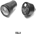
- FIG. 9 depicts an example head module on the left and an example tail module on the right.
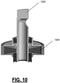
- FIG. 10 is a diagram depicting a rotatable shaft with which an actuator interacts to impart motion on an example module of an electro-mechanical system.
- the actuator is configured to apply a torque to the shaft 1002, which sits in the first segment of a module, as depicted at 602 in FIG. 6 , rotating the second segment, as depicted at 604 in FIG. 6 .
- An elastic element 1004, such as the tapered elastic element depicted in FIG. 10 has a shearing force applied to it when the actuator rotates the shaft 1004.
- the shearing force applied to the elastic element 1004 for different degrees of rotation of the shaft 1002 is predictable, such that the actuator and processor know an amount of torque to impart on the shaft 1002 to achieve a desired amount of rotation of the module segments.
- Periodic re-calibration operations can be performed to update necessary levels of torque for achieving desired rotation amounts, such as to address changing conditions of the elastic element 1004 or other aspects of the module.
- FIG. 11 depicts a cross-section of the example module shown in FIG. 6 .
- an elastic element 1102 that has a conical taper cross-section is embedded in a final stage of a gear train 1104 of the module.
- the elastic element 1102 includes a conically shaped layer of rubber molded into the final stage.
- the module includes two encoders 1106 (e.g., magnetic encoders) that measure the input and output angles of the elastic element 1102.
- Calibration for the actuator can be performed using one or more models (e.g., linear models, Norton/Thevenin damped models, Buc-Wen hysteresis models) of which certain parameters of the current state of the actuator can be determined, e.g., based on motor current and/or internal sensors (such as encoders and temperature sensors).
- models e.g., linear models, Norton/Thevenin damped models, Buc-Wen hysteresis models
- certain parameters of the current state of the actuator can be determined, e.g., based on motor current and/or internal sensors (such as encoders and temperature sensors).
- calibration for the actuator is performed by measuring a motor current of the actuator's highly geared motor and using a simple linear model for an estimated torque of the elastic element 1102.
- a recursive estimation technique e.g., a recursive least squares technique, an unscented Kalman filter
- the actuator utilizes a Maxon EC 20 flat motor with a nominal speed of 9300 RPM.
- the steel pinion gear on the motor's output shaft transfers rotation through a gear train containing three steel and brass compound gears.
- the cumulative gear ration is 349:1 to create high-torque joints.
- Such a motor and gear train combination can provide a maximum output torque of 7 Nm and a maximum speed of 33 RPM.
- FIG. 12 depicts a block diagram for providing module motion control, such as for the module depicted in FIGS. 6-9 .
- the module supports angular position, velocity, and torque control through cascaded PID control.
- each PID controller operates at 1 kHz, although target set points may be updated less frequently (e.g., at 100-200 Hz).
- Independent position and velocity outer loops generate torque commands, which are combined with a desired feed-forward torque to define a set point for output torque which is maintained by the inner torque controller.
- the inner torque controller is able to directly compare desired and actual output torque by directly observing spring deflection as the difference between the two encoder positions.
- This error is used to compute a PWM command to the motor which applies appropriate torque to the input of the spring and gear train.
- additional features are added to help compensate for common gear train nonlinearities. For example, to prevent oscillations due to gear backlash and sensor noise, a 'deadzone' is added within which errors are assumed to be zero. To overcome gear train stiction, a 'punch' factor can be added. Maximum output limits can also be set for each controller. To mitigate windup of the integral term, its output can be limited to the difference between the PD output and the set output level. For example, using this method, if PD control already reaches this level, the integral term can be reduced to 0.
- FIG. 13 is a block diagram depicting a module 1302 having modeling capabilities at its processor 1304.
- the data processor 1304 implements a model 1306 for modeling a physical parameter of the module without direct measurement of that physical parameter.
- the module may include a sensor for measuring a second parameter of a same or different type as the physical parameter to be modeled. Based on the modeled physical parameter, the processor 1304 can take action, such as commanding the actuator 1308 to impart motion on the module 1302 in a certain way.
- the model 1306 operates to estimate a certain temperature within the module 1302.
- An important challenge for electro-mechanical systems is to safely extract as much performance as possible out of their actuators 1308 without damaging the actuators.
- the primary limitation on performance is often heat buildup in the motor windings.
- direct measurement of such temperature is difficult due to location inaccessibility.
- a module uses online estimation of its actuator motor winding temperature to fully exploit the motor's performance envelope beyond its continuous duty ratings.
- the estimated winding temperature is based on a second temperature sensor in the module 1302 that is near the motor, the sensed current draw of the motor, and a model of the internal thermal resistances and capacitances of the motor. These inputs are provided to model 1306, which outputs an estimated temperature of the model. If the estimated temperature indicates a sufficiently low temperature, the actuator motor can be overdriven without fear of damaging the motor.
- torque sensing is performed using a model.
- a spring constant of the elastic element described above is calibrated.
- One approach uses an unscented Kalman filter and a heuristic function that takes into account the motor's motion and current draw.
- a state estimator incorporates models of hysteresis and other non-linear effects, and integrates this estimator into the firmware of the module 1302.
- the spring coefficient of an elastic element is modeled periodically based on certain measurements of other module 1302 parameters of different types. That adjusted spring coefficient can then be used in identifying an amount of torque to be applied to the shaft to produce a desired amount of rotation.
- Modules as described herein may include a variety of sensors for sensing their own state and the state of the environment in which they reside.
- FIG. 14 is a block diagram depicting a module having integrated sensors whose data is provided to a processor and other external entities.
- a module 1402 includes a suite of one or more sensors 1404 that communicate data to a processor 1406.
- certain modules may include sensors for detecting the state of their associated module, such as an inertial measurement unit, a 3-axis gyroscope, a 3-axis accelerometer, a 3-axis magnetometer, a voltage sensor, a temperature sensor, a current sensor, or an actuator torque sensor.
- Other modules may include different sensors. For instance, a head module of a snake robot configuration could include a camera sensor.
- Sensor data can be consumed internally by the processor 1406, such as for adjusting operations (e.g., actuator 1408 function) of the module 1402.
- the module 1402 may further transmit sensor data to its exterior via a communication channel and a switch 1410.
- the module 1402 may use an Ethernet standard to send sensor data in packet form, where a single packet could contain data from multiple sensors 1404 of the module.
- FIG. 15 is a block diagram depicting a module 1502 that communicates data to the exterior via one or more lights 1504 visible at the exterior of the module. The lights are detectable externally to the module 1502 via an external light sensor 1506. Based on light detected by the sensor 1506, that external entity or other module can receive data from the module 1502 or detect a state of the module 1502. For example, a light 1504 may be on when a module is powered such that detection of such light at 1506 indicates that the module 1502 is on to the external entity.
- the light is positioned at a certain position of the module 1502, such that detection of the light (or inability to detect the light because it is pointed away from the sensor) at 1506 gives an external entity data about the orientation of the module 1502.
- Multiple lights of different colors could be positioned at particular points on the module 1502 to give further details on orientation of the module.
- the lights could also be varied in wavelength, brightness, or pulsed to indicate module 1502 state data or other data that the module 1502 wishes to send, such as values extracted from sensors of the module 1502.
- Modules may be configured with certain firmware that provides instructions for an onboard processor and other components.
- a firmware core is a real-time operating system (RTOS) that is configured to separate setup and upkeep of various hardware modules into separate thread.
- RTOS real-time operating system
- ChibiOS/RT is selected for its out-of-the-box support for STM32 Cortex processors and a hardware abstraction layer that supports peripherals such as Ethernet, serial, analog-digital conversion, and pulse-width modulation.
- Low-level control code can include 1 kHz cascaded PID loops for simultaneous position, velocity, and toque control; steady-state Kalman filtering of actuator velocity; multiple sensor readings, including two encoders and an internal IMU; thermal modeling of motor winding temperature; and identification of adjacent modules to auto-discover an electro-mechanical system's configuration.
- Modules may be configured to communicate with each other and external entity client software via a messaging protocol, such as Google Protocol Buffer messages.
- Protocol Buffers define a fixed serialization format for typed data structures that are supported across multiple computing platforms.
- the Google C++ library can be ported for Protocol Buffers to ChibiOS to allow messages to be encoded and decoded on the module.
- remote-procedure calls RPC
- a single "meta"-message is defined that defines a number of optional fields that can encode module parameters and data streams.
- a computing environment with Protocol Buffer support can then interact with the electro-mechanical system by sending and receiving of these meta-messages.
- Such a protocol can be implemented being fundamentally stateless, and messages can be handled transactionally, naturally supporting multiple concurrent asynchronous connections.
- the protocol can be exposed identically over Transmission Control Protocol (TCP) sockets, User Datagram Protocol (UDP) sockets, and a serial interface between modules, allowing a variety of flexible communication strategies to be used in various situations, depending on available bandwidth, required level of control, and interface hardware.
- Modules can propagate local information, such as their configuration, by exchanging data over a serial interface to neighboring modules.
- An electro-mechanical system can utilize certain software architectural styles as a foundation for its framework.
- a first, pipe-and filter style is a data flow pattern often found in systems that process real-time data.
- the style typically consists of two elements: filters that apply incremental transformations to data streams and pipes which are unidirectional connectors between filters. Filters have no knowledge of the identities of other filters and share no state between each other.
- LCM Lightweight Communications and Marshalling
- LCM is a low-latency publish-subscribe implementation that uses UDP multicast as the basis for broadcasting messages to components.
- Using multicast means that, unlike TCP based message passing services, LCM does not require a centralized manager to forward data to appropriate subscribers. This enables components to communicate directly and to be started and stopped at any time and in any order. This lower overhead may come at the price of guaranteed delivery. In one example, such guaranteed delivery can be restored using other mechanisms. Communications that require reliable delivery (such as that provided by TCP) could be handled using other mechanisms.
- LCM supports several languages including C, C++, Java, Python, and MATLAB, and supports Windows, Linux, Mac, and some embedded platforms.
- filters For control and estimation of robotic systems, typical filters (e.g., pose estimation or high-level autonomous control behaviors) can be more effective if their internal state and parameters are visible to and dynamically modifiable by a human operator at run-time. This allows for more efficient debugging and parameter tuning, and is often required for cases of supervised autonomy. Because of these reasons, a standard way to interface with various filter-elements at runtime can be adopted, even when there is no prior knowledge of the active elements and their internal parameters. To further complicate the challenge, filters can differ significantly in purpose, method, and perhaps even language in which they are implemented. For example, MATLAB can be used for prototyping and developing filters and controls with complex math operations, C/C++ can be used for stable code that has significant performance requirements, and Java can be used for filters that need to run cross platform.
- MATLAB can be used for prototyping and developing filters and controls with complex math operations
- C/C++ can be used for stable code that has significant performance requirements
- Java can be used for filters that need to run cross platform.
- a system can define the concept of behaviors, or filter blocks with common interface elements called behavior parameters that are visible and modifiable at run-time through an event bus. While this can use the same publish-subscribe framework as the pipe-and-filter structure mentioned previously, it can be conceptually separate.
- a behavior parameter is a simple data object combining a typed variable and an allowed range for its values (allowing constraints such as restricting a PID constant to be strictly positive).
- a system can dedicate two event channels for the behavior mechanism. The first is a parameter change channel on which parameter change events get published. Behaviors listen to this channel and react to events for which they are targets. The second channel is a behavior state broadcast channel on which individual behaviors publish their full internal state whenever one of their parameters changes or upon request.
- a system implements behaviors in C++, Java, and MATLAB.
- FIG. 16 depicts an example user interface which allows operators to: observe any running behaviors on the network; stop active behaviors; start known inactive behaviors; and view and change behavior parameters through appropriate controls. Such an interface allows for a simple and generic way to modify internal behavior parameters without requiring modifications to underlying code.
- modules can be configured to perform operations to identify their configuration in an electro-mechanical system. For example, in an electro-mechanical system having a series of connected modules, the modules can be configured to determine the order in which they appear in the series (e.g., first, second, third in a snake or leg of an electro-mechanical system). Such detection can take the place of manual identification (e.g., manual setting of IP addresses), enabling faster and more flexible plug-and-play type setup.
- modules can be configured to perform operations to identify their configuration in an electro-mechanical system. For example, in an electro-mechanical system having a series of connected modules, the modules can be configured to determine the order in which they appear in the series (e.g., first, second, third in a snake or leg of an electro-mechanical system). Such detection can take the place of manual identification (e.g., manual setting of IP addresses), enabling faster and more flexible plug-and-play type setup.
- FIG. 17 is a block diagram depicting one mechanism for modules to identify their position in a series of modules.
- the diagram depicts a plurality of modules 1702, 1704, 1706, each including a switch 1703, 1705, 1707, respectively.
- the modules 1702, 1704, 1706 are connected to an external entity 1708, from which commands are received.
- the external entity 1708 issues commands to the modules 1702, 1704, 1706 to identify the position of the modules in the series. Once a module knows its position, it can respond to commands and data directed to it from the external entity 1708 or other modules.
- the modules 1702, 1704, 1706 and the external entity 1708 are configured to detect a number of modules (n) that are incorporated into the system and a position of those modules in the system. This can be accomplished by commanding all of the modules 1702, 1704, 1706 to open the incoming port of their switches 1703, 1705, 1707 and close the output port of those switches.
- a signal is transmitted by the external entity 1708 (e.g., a packet saying that this is a message for the first module) along the communication channel that runs through the series of modules 1702, 1704, 1706. Only the first module 1702 will receive that signal because the outbound port of switch 1703 is closed. When the first module 1702 receives the signal, it stores an indicator that it is the first module in the series.
- the first module 1702 then opens the outbound port of its switch 1703 and sends an acknowledgment to the external entity 1708.
- the external entity 1708 then sends a second signal that is received by the first module 1702 and the second module 1704.
- the first module already having been identified as first-in-line ignores the signal, while the second module 1704 realizes that it is second in line and stores an indicator of that fact.
- the second module 1704 opens the outbound port of its switch 1705 and sends an acknowledgment to the external entity 1708 and the process repeats. The process is repeated until no acknowledgment is received by the external entity 1708. Based on this lack of acknowledgment, the external entity 1708 then knows the number of modules (e.g., 3) in the series of connected modules.
- modules are configured to change operational characteristics (e.g., switching send and receive ports on a serial interface), where neighboring modules can detect changed characteristics and ascertain their relative positioning.
- operational characteristics e.g., switching send and receive ports on a serial interface
- FIGS. 18-20 depict a T-slot compatible module for imparting a torque on a wheel and an external component connected to the wheel.
- a T-slot compatible module as depicted in FIG. 18 , is compatible with existing T-slot compatible hardware, where the module includes T-slots on its four sides for easy connection.
- the module utilizes standard T-slot aluminum (e.g., compatible with 80/20 brand 10-series products) and uses standard 1-inch bolt patterns to enable connection into existing setups and new designs with little time and effort.
- the T-slot compatible module includes an integrated servoactuator for imparting a torque on a wheel portion 1802 of the module.
- Hardware can be attached to the wheel portion 1802, such as via integrated screw receptors.
- the actuator applies a torque to the wheel portion 1802 which imparts rotational motion on a turnable body connected to the wheel portion.
- the T-slot compatible module is connectable to other modules both physically and for communication of data. At the electrical level, the communication can be handled over standard Ethernet using Google's extensible Protocol Buffers protocol.
- the module can include sensors that enable 3-axis inertial measurement, controllable motor velocity, and high-bandwidth controllable torque output through a dual-encoder series elastic stage after the gear train.
- FIG. 19 is a block diagram depicting example components of the T-slot compatible module of FIG. 18 .
- the module 1902 includes a processor 1904 that is configured to communicate to the outside of the module 1902 via a communication channel 1906.
- An actuator 1908 is responsive to the processor 1904 for imparting motion in the module 1902 by rotating a wheel portion 1910 of the module 1902 on command.
- the wheel portion 1910 is configured to have an external component 1912 connected to it (e.g., via screws or other fasteners), such that the rotation of the wheel portion 1910 also rotates the external component 1912.
- a position of the wheel portion 1910 is monitored, such as part of a feedback loop to the processor 1904 to maintain proper positioning of the wheel portion 1910.
- FIG. 20 is a photograph depicting a beam 2002, connected to a module 2004 having a rotatable wheel portion that is rotated by an actuator.
- the beam 2002 is connected to the module 2004 via a bracket and screws 2006. While the examples of FIGS. 18-20 depict imparting a torque on a wheel component of a module, in other examples, torques and rotations can be imparted in other structures of modules as well as external structures connected to modules.
- FIG. 21 is a diagram depicting an interface module that includes no internal actuators or sensors. Similar to other modules described herein, the module 2102 of FIG. 21 includes a processor 2104 and a switch 2106 that interacts with a communication channel to communicate with other modules or an external entity. The module 2102 of FIG. 21 further includes a communication port 2108. External actuators or sensors can be connected to the communication port 2108 (e.g., via a USB connection) to provide extra capabilities to the electro-mechanical system. In one embodiment, such external peripherals can be incorporated into the system in a plug-and-play fashion, communicating with other entities via an Ethernet communication channel, offering a high degree of system customization.
- FIG. 22 depicts another module type in the form of a gripper module.
- the gripper module 2202 includes an interface portion 2204 for facilitating both a physical and data connection to other modules or other outside entities.
- the gripper portion includes two paddles 2206, 2208 that can be controllably manipulated via a processor and actuator to perform desired functions, such as gripping functions.
- a first paddle 2206 is rigidly attached to the gripper module 2202 and does not move.
- a second paddle 2208 is connected to the gripper module 2202 via a shaft 2210 that is rotatable by the actuator that is internal to the gripper module 2202.
- the module 2202 may include a variety of sensors for enhancing the operation of the gripper module 2202.
- a torque sensor could be incorporated with an internal elastic actuator to provide feedback as to whether the second paddle 2208 has been moved to a desired position.
- a force sensor could be incorporated to sense an amount of force felt by one of the paddles. Limitations on such force in a control algorithm operated by a processor internal to the gripper module 2202 could enable gentle gripping by the gripper module without damage to the module 2202 or objects being grasped.
- the gripper module 2202 could be incorporated into a wide variety of electro-mechanical systems, including the multi-legged robot of FIG. 4 , where such a gripper module could operate as a head module (e.g., a mouth) or at the end of one or more of the legs (e.g., as hand(s)).
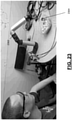
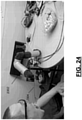
- FIGS. 23-25 depict example operations of electro-mechanical systems.
- FIGS. 23-24 depict an electromechanical system 2302 having a fork 2304 connected, the system 2302 being configured to pierce food onto the fork 2304 and translate that food to a person's mouth.
- the example of FIGS. 23-24 illustrates a soft real time/hard real time software configuration.
- the system is trained by manually positioning the electromechanical system 2302 at a number of positions (e.g., piercing food, 3 positions along the translation to the mouth, and a final position depicted in FIG. 24 where food is removed by the mouth).
- Those positions of the electro-mechanical system are recorded by an external entity.
- the external entity then commands playback of those positions as soft real time commands to the modules of the electro-mechanical system 2302.
- Those soft real time commands indicate a result to be achieved (i.e., the electro-mechanical system at one of the recorded positions).
- the processors of the modules of the electro-mechanical system 2302 are configured to achieve the commanded positions based on self-sensing of their current position and configuration.
- the module processors issue commands to their actuators as hard real time commands that must be completed in a known period of time, where those actuator operations in concert produced the desired system 2302 configuration.
- FIG. 25 depicts an electro-mechanical system 2502 configured to rotate in a plane, as indicated at 2504.
- a sensor in one of the modules of the system 2502 detects an obstruction, provided in the example of FIG. 25 by a hand 2506.
- Such sensing could be performed in a variety of manners, such as a sensing of increased torque needed to provide the commanded motion, an accelerometer, a vibration sensing, or otherwise.
- the modules of the system 2502 upon sensing an unexpected system event, such as the interruption by the hand, the modules of the system 2502 are configured to take a protective action to mitigate damage to the system 2502 or the obstruction 2506.
- the system 2502 may be configured to stop, reverse direction, or determine a different path for reaching their commanded end point as programmed, preferably to maintain the safety of the system 2502 and the obstruction 2506.
- an anomaly detected by a sensor at one module can be utilized globally in the electro-mechanical system, which in one embodiment results in coordinated action based on the detected anomaly.
Claims (15)
- Elektromechanisches System, umfassend:
eine Mehrzahl verbundener Module, wobei ein erstes Modul (100, 102, 202, 1702) der Module umfasst:einen Aktuator (104, 214, 1308, 1408, 1908) zur Übertragung von Bewegung auf das elektromechanische System;einen Datenprozessor (106, 212, 304, 1304, 1406, 1904, 2104), der eingerichtet ist, einen Zustand des ersten Moduls (100, 102, 202, 1702) zu erfassen und den Aktuator (104, 214, 1308, 1408, 1908) dazu zu steuern, den Zustand des ersten Moduls (100, 102, 202, 1702) zu modifizieren, um einen empfangenen Befehl zu erfüllen;wobei das erste Modul (100, 102, 202, 1702) ferner eine Schnittstelle zum Erreichen einer physischen Verbindung (206) und einer Datenverbindung mit einem zweiten Modul (108, 204, 1704) von den verbundenen Modulen umfasst, dadurch gekennzeichnet, dass das erste Modul (100, 102, 202. 1702) ferner einen mindestens drei Ports umfassenden Schalter (108) umfasst, wobei ein erster Port für Kommunikation mit dem zweiten Modul (108, 204, 1704) eingerichtet ist, wobei ein zweiter Port für Kommunikation mit einem dritten Modul eingerichtet ist und wobei ein dritter Port für Kommunikation mit dem Datenprozessor (106, 212, 304, 1304, 1406, 1904, 2104) eingerichtet ist. - System nach Anspruch 1, wobei mindestens zwei der verbundenen Module identische Module sind oder das System dazu eingerichtet ist, unter Verwendung von zwischen 2 und N verbundenen Modulen zu arbeiten, wobei N eine natürliche Zahl größer 2 ist.
- System nach Anspruch 1, wobei das erste Modul (100, 102, 202, 1702) dazu eingerichtet ist, einen Freiheitsgrad in einer ersten Ebene aufzuweisen;
wobei ein zweites Modul (108, 204, 1704), das mit dem ersten Modul (100, 102, 202, 1702) verbunden ist, dazu eingerichtet ist, einen Freiheitsgrad in einer zweiten Ebene, die sich von der ersten Ebene unterscheidet, aufzuweisen, wobei vorzugsweise entweder die zweite Ebene senkrecht zu der ersten Ebene ist oder ein erstes Ende (216) des ersten Moduls (202) dazu eingerichtet ist, sich relativ zu einem zweiten Ende (218) des ersten Moduls (202) in der ersten Ebene zu drehen. - System nach Anspruch 1, wobei(i) die Schnittstelle des ersten Moduls (100, 102, 202, 1702) einen Gewindering (110) aufweist, der dazu eingerichtet ist, sich mit einer Schnittstelle des zweiten Moduls (108, 204, 1704) zu verbinden; oder(ii) das erste Modul (100, 102. 202, 1702) dazu eingerichtet ist, mit dem zweiten Modul (108, 204, 1704) über einen Ethernet-Standard zu kommunizieren, wobei vorzugsweise das erste Modul (100, 102, 202, 1702) ferner dazu eingerichtet ist, mit einer externen Entität (1708) über den Ethernet-Standard zu kommunizieren, und wobei sämtliche Kommunikation zwischen dem ersten Modul (100, 102, 202, 1702), dem zweiten Modul (108, 204, 1704) und der externen Entität (1708) über den Ethernet-Standard erfolgt.
- System nach Anspruch 1, wobei das System dazu eingerichtet ist, eine Anzahl n der verbundenen Module, die in das System integriert sind, zu erkennen, wobei n eine natürliche Zahl größer 2 ist und wobei das erste Modul (100, 102, 202, 1702) dazu eingerichtet ist, seine Position in einer Reihe von mindestens zwei verbundenen Modulen zu bestimmen, wobei vorzugsweise(i) das erste Modul (100, 102, 202, 1702) dazu eingerichtet ist, seine Position zu bestimmen durch: Aktivieren eines Eingabeports des ersten Moduls (100, 102, 202, 1702) und Deaktivieren des Ausgabeports des ersten Moduls (100, 102, 202, 1702) und anderer Module in der Reihe bei Initialisierung;Übertragung eines Signals von einer externen Entität (1708) an ein anfängliches Modul in der Reihe von Modulen, wobei auf der Basis des deaktivierten Ausgabeports des ersten Moduls (100, 102, 202, 1702) nur das anfängliche Modul das Signal empfängt;Speichern eines Indikators an dem anfänglichen Modul, dass es Modul Nummer eins ist; Aktivieren des Ausgabeports des anfänglichen Moduls;Übertragung eines zweiten Signals von der externen Entität (1708), wobei auf der Basis des deaktivierten Ausgabeports des folgenden Moduls das anfängliche Modul und ein unmittelbar folgendes Modul das zweite Signal empfangen;Speichern eines Indikators an dem folgendem Modul, dass es Modul Nummer zwei ist; oder(ii) das erste Modul (100, 102, 202, 1702) dazu eingerichtet ist, seine Position durch Erkennen einer Veränderung in einem Konfigurationsmerkmal eines zweiten Moduls (108, 204, 1704), das direkt mit dem ersten Modul (100, 102, 202, 1702) verbunden ist, zu bestimmen, wobei vorzugsweise die Konfigurationsmerkmalsveränderung ein Austausch von einem Übertragungs- und einem Empfangskanal an dem zweiten Modul (108, 204, 1704) ist.
- System nach Anspruch 1, wobei der Datenprozessor (106, 212, 304, 1304, 1406, 1904, 2104) ein Modell zum Modellieren eines physischen Parameters des ersten Moduls (100, 102, 202, 1702) auf der Basis eines zweiten Parameters, der ein anderer Typ als der physische Parameter ist, implementiert, wobei der Datenprozessor (106, 212, 304, 1304, 1406, 1904, 2104) dazu eingerichtet ist, den Aktuator (104, 214, 1308, 1408, 1908) auf der Basis des modellierten physischen Parameters zu steuern, wobei vorzugsweise der physische Parameter(i) ein Temperaturparameter ist, wobei der Datenprozessor (106, 212, 304, 1304, 1406, 1904, 2104) dazu eingerichtet ist, den Aktuator (104, 214, 1308, 1408, 1908) auf der Basis dessen, dass der modellierte Temperaturparameter unter einem vorbestimmten Niveau liegt, über einen Schwellenwert hinaus zu übersteuern; oder(ii) ein Federkoeffizient einer elastischen Komponente des Aktuators (104, 214, 1308, 1408, 1908) ist, wobei das erste Modul (100, 102, 202, 1702) dazu eingerichtet ist, sich periodisch zu kalibrieren, um den Federkoeffizienten anzupassen, wobei vorzugsweise der Datenprozessor (106, 212, 304, 1304, 1406, 1904, 2104) dazu eingerichtet ist, den Aktuator (104, 214, 1308, 1408, 1908) dazu zu steuern, auf der Basis einer gewünschten Position des ersten Moduls (100, 102, 202, 1702) und des angepassten Federkoeffizienten ein Drehmoment an die elastische Komponente anzulegen.
- System nach Anspruch 1, wobei das erste Modul (100, 102, 202, 1702) dazu eingerichtet ist, Sensordaten von einer Mehrzahl von Sensoren in Paketform an eine externe Entität (1708) zu senden, wobei ein einzelnes Paket Daten von mehreren Sensoren enthält, die dem ersten Modul (100, 102, 202, 1702) zugeordnet sind.
- System nach Anspruch 1, wobei das System ferner so eingerichtet ist, dass es ein einzigartiges Modul aufweist, das sich von allen anderen Modulen unterscheidet.
- System nach Anspruch 1, wobei das System dazu eingerichtet ist, ein Modul zu umfassen, das einen Servoaktuator aufweist, der dazu eingerichtet ist, ein Drehmoment an einen Radabschnitt (1802, 1910) des Servoaktuatormoduls anzulegen, wobei vorzugsweise das Servoaktuatormodul eine Mehrzahl von T-Schlitz-Rahmenabschnitten umfasst oder der Radabschnitt (1802, 1910) dazu eingerichtet ist, mit einem drehbaren Körper verbunden zu sein, wobei vorzugsweise entweder ein Zustand des Radabschnitts (1802, 1910) auf der Basis einer anfänglichen niedrig aufgelösten Messung und einer Mehrzahl anschließender hoch aufgelöster Messungen detektiert wird oder die niedrig aufgelöste Messung eine ungefähre Position des Radabschnitts (1802, 1910) erkennt und wobei die hoch aufgelösten Messungen eine Drehung des Radabschnitts (1802, 1910) aus der ungefähren Position erkennen.
- System nach Anspruch 1, wobei das erste Modul (100, 102, 202, 1702) ein oder mehrere Lichter (1504) umfasst, wobei eine Kamera außerhalb des ersten Moduls (100, 102, 202, 1702) auf der Basis des einen oder der mehreren Lichter (1504) einen Zustand des ersten Moduls (100, 102, 202, 1702) bestimmt, wobei vorzugsweise der Zustand auf der Basis einer Farbe, einer Helligkeit oder eines Blinkens des einen oder der mehreren Lichter (1504) bestimmt wird.
- System nach Anspruch 1, wobei ein erster Befehl von einer externen Entität (1708) an das erste Modul (100, 102, 202, 1702) als weicher Echtzeitbefehl übertragen wird, wobei, auf der Basis des ersten Befehls, der Datenprozessor (106, 212, 304, 1304, 1406, 1904, 2104) einen zweiten Befehl an den Aktuator (104, 214, 1308, 1408, 1908) ausgibt, der ein harter Echtzeitbefehl ist.
- System nach Anspruch 1, wobei ein erster Befehl von einer externen Entität (1708) an das erste Modul (100, 102, 202, 1702) gesendet wird, der ein Endergebnis des Systems, das die Mehrzahl verbundener Module umfasst, steuert, wobei der Datenprozessor (106, 212, 304, 1304, 1406, 1904, 2104) des ersten Moduls (100, 102, 202, 1702) und Datenprozessoren (106, 212, 304, 1304, 1406, 1904, 2104) anderer Module Zwischenbefehle an zugeordnete Aktuatoren (104, 214, 1308, 1408, 1908) bestimmen, um das Endergebnis zu erzielen.
- System nach Anspruch 1, ferner umfassend eine der Alternativen:(i) ein Kopfmodul (504), das mit genau einem der verbundenen Module verbunden ist, wobei das Kopfmodul (504) einen oder mehrere Sensoren aufweist, die nicht auf den verbundenen Modulen vorhanden sind, wobei vorzugsweise das Kopfmodul (504) einen Kamerasensor aufweist;(ii) ein Endmodul (506), das mit genau einem der verbundenen Module verbunden ist, wobei das Endmodul (506) einen Kommunikationsmechanismus zum Kommunizieren mit einer externen Entität (1708) aufweist, wobei der Kommunikationsmechanismus ein drahtgebundener oder drahtloser Kommunikationsmechanismus ist; oder(iii) ein Schnittstellenmodul, wobei das Schnittstellenmodul mit einem der verbundenen Module verbunden ist, wobei das Schnittstellenmodul keinen integralen Freiheitsgrad aufweist, wobei das Schnittstellenmodul einen oder mehrere Ports zur Verbindung mit einem Sensor oder einem Aktuator (104, 214, 1308, 1408, 1908) aufweist.
- System nach Anspruch 1, wobei(i) die Kommunikation unter den verbundenen Modulen oder zwischen einer externen Entität (1708) und dem ersten Modul (100, 102, 202, 1702) verschlüsselt ist; oder(ii) das erste Modul (100, 102, 202, 1702) so einrichtbar ist, dass es mit anderen Modulen verbunden ist, um einen Schlangenroboter auszubilden; und wobei das erste Modul (100, 102, 202, 1702) so einrichtbar ist, dass es mit anderen Modulen verbunden ist, um einen mehrbeinigen Roboter mit 1 bis n Beinen auszubilden, wobei n eine natürliche Zahl größer 1 ist.
- System nach Anspruch 1, wobei das elektromechanische System ein Roboter oder ein System, das bei der Automatisierung verwendet wird, ist.
Applications Claiming Priority (3)
| Application Number | Priority Date | Filing Date | Title |
|---|---|---|---|
| US201461991078P | 2014-05-09 | 2014-05-09 | |
| US201461991665P | 2014-05-12 | 2014-05-12 | |
| PCT/US2015/030088 WO2015172131A1 (en) | 2014-05-09 | 2015-05-11 | Systems and methods for modular units in electro-mechanical systems |
Publications (3)
| Publication Number | Publication Date |
|---|---|
| EP3148752A1 EP3148752A1 (de) | 2017-04-05 |
| EP3148752A4 EP3148752A4 (de) | 2018-05-09 |
| EP3148752B1 true EP3148752B1 (de) | 2022-01-19 |
Family
ID=54367023
Family Applications (1)
| Application Number | Title | Priority Date | Filing Date |
|---|---|---|---|
| EP15789830.5A Active EP3148752B1 (de) | 2014-05-09 | 2015-05-11 | Systeme und verfahren für moduleinheiten in elektromechanischen systemen |
Country Status (4)
| Country | Link |
|---|---|
| US (1) | US9597796B2 (de) |
| EP (1) | EP3148752B1 (de) |
| CN (1) | CN106660203B (de) |
| WO (1) | WO2015172131A1 (de) |
Families Citing this family (30)
| Publication number | Priority date | Publication date | Assignee | Title |
|---|---|---|---|---|
| WO2014138439A1 (en) * | 2013-03-06 | 2014-09-12 | Massachusetts Institute Of Technology | Discrete motion system |
| GB2531576B (en) | 2014-10-22 | 2018-04-25 | Q Bot Ltd | Modular Robot |
| CN106272398A (zh) * | 2015-05-27 | 2017-01-04 | 鸿富锦精密工业(深圳)有限公司 | 机器人的驱动组件、机器人及机器人系统 |
| JP6576118B2 (ja) * | 2015-06-25 | 2019-09-18 | キヤノン株式会社 | 駆動制御装置及びそれを有するレンズ装置、撮影システム |
| JP6657824B2 (ja) * | 2015-11-13 | 2020-03-04 | 株式会社デンソーウェーブ | ロボットのハンド接続構造 |
| US9796081B2 (en) * | 2015-11-25 | 2017-10-24 | Tata Consultancy Services Limited | Robotic snake |
| JP6108645B1 (ja) * | 2016-01-31 | 2017-04-05 | 貴司 徳田 | モーターモジュールシステム |
| CA3213027A1 (en) * | 2016-02-02 | 2017-08-10 | Deka Products Limited Partnership | Modular electro-mechanical agent |
| EP3216569A1 (de) * | 2016-03-07 | 2017-09-13 | Aldebaran Robotics | Modulare herstellung eines roboters |
| US10315309B2 (en) * | 2016-03-15 | 2019-06-11 | Lon Radin | Modular snake arm with articulated drive shaft |
| NO341639B1 (no) * | 2016-05-22 | 2017-12-18 | Grip Robotics As | Kompakt elektrisk høymomentaktuator og tilhørende metodeverkt for bygging av "motion" systemer |
| JP2018062028A (ja) * | 2016-10-12 | 2018-04-19 | ファナック株式会社 | モジュールの情報を追跡するロボットシステム及び保守方法 |
| US10667105B2 (en) * | 2017-04-24 | 2020-05-26 | Pilot Inc. | Bluetooth enabled snake cam |
| US10511515B1 (en) * | 2017-08-29 | 2019-12-17 | Rockwell Collins, Inc. | Protocol buffer avionics system |
| EP3476549A1 (de) * | 2017-10-27 | 2019-05-01 | Creaholic SA | Hardware-modul, robotersystem und verfahren zum betrieb des robotersystems |
| EP3476545A1 (de) * | 2017-10-27 | 2019-05-01 | Creaholic SA | Verfahren zum betrieb eines computergestützten inventars von hardwaremodulen eines robotersystems |
| CN108274458B (zh) * | 2017-12-19 | 2020-12-18 | 北京可以科技有限公司 | 用于构建模块化机器人的子单元模块 |
| FR3079081B1 (fr) * | 2018-03-19 | 2022-12-09 | Naval Energies | Connecteur de raccordement de cables sous-marins et notamment de cables ombilicaux pour des fermes d'energie marine renouvelable |
| FR3080556B1 (fr) * | 2018-04-30 | 2021-02-12 | Arnaud Cueille | Robot modulaire reconfigurable |
| US11305420B2 (en) * | 2018-05-31 | 2022-04-19 | Virginia Tech Intellectual Properties, Inc. | Articulated multi-link robotic tail systems and methods |
| US11421656B2 (en) * | 2019-01-03 | 2022-08-23 | Lucomm Technologies, Inc. | Generative system |
| US11396105B2 (en) * | 2019-02-21 | 2022-07-26 | Abb Schweiz Ag | Sensor module for a robot |
| US11155326B2 (en) * | 2019-03-29 | 2021-10-26 | The Hong Kong Polytechnic University | Bio-inspired underwater robot |
| JP7437910B2 (ja) * | 2019-10-29 | 2024-02-26 | 株式会社東芝 | 制御システム、制御方法、ロボットシステム、プログラム、及び記憶媒体 |
| CN112356015B (zh) * | 2020-09-30 | 2022-04-01 | 浙江理工大学 | 一种仿生蛇形蠕动机器人 |
| KR102368762B1 (ko) * | 2020-10-27 | 2022-02-28 | 오승섭 | 모듈형 센서 교체형 다족보행 로봇 |
| CN113183144A (zh) * | 2021-05-13 | 2021-07-30 | 上海大学 | 一种线缆驱动的滚动关节连续体机械臂 |
| US11926048B2 (en) * | 2021-05-26 | 2024-03-12 | Amazon Technologies, Inc. | Modular robotic linkages |
| CN113479306B (zh) * | 2021-08-03 | 2024-02-27 | 景兴建 | 一种设有浮力调节装置的仿生水下机器人 |
| EP4272905A1 (de) * | 2022-05-06 | 2023-11-08 | Technische Universität München | Modulares robotersystem |
Family Cites Families (45)
| Publication number | Priority date | Publication date | Assignee | Title |
|---|---|---|---|---|
| US5355743A (en) * | 1991-12-19 | 1994-10-18 | The University Of Texas At Austin | Robot and robot actuator module therefor |
| US6686717B2 (en) * | 1997-04-01 | 2004-02-03 | Charles Khairallah | Modular articulated structure |
| GB9713765D0 (en) * | 1997-07-01 | 1997-09-03 | Engineering Services Inc | Reconfigurable mudular drive system |
| JP2001038663A (ja) * | 1999-07-28 | 2001-02-13 | Yamaha Motor Co Ltd | マシンの制御システム |
| US6993456B2 (en) * | 1999-09-30 | 2006-01-31 | Rockwell Automation Technologies, Inc. | Mechanical-electrical template based method and apparatus |
| US6988008B2 (en) * | 2000-03-10 | 2006-01-17 | Adept Technology, Inc. | Smart camera |
| US6450104B1 (en) * | 2000-04-28 | 2002-09-17 | North Carolina State University | Modular observation crawler and sensing instrument and method for operating same |
| US6636781B1 (en) * | 2001-05-22 | 2003-10-21 | University Of Southern California | Distributed control and coordination of autonomous agents in a dynamic, reconfigurable system |
| US6605914B2 (en) * | 2001-08-24 | 2003-08-12 | Xerox Corporation | Robotic toy modular system |
| US6454624B1 (en) * | 2001-08-24 | 2002-09-24 | Xerox Corporation | Robotic toy with posable joints |
| US8375838B2 (en) * | 2001-12-14 | 2013-02-19 | Irobot Corporation | Remote digital firing system |
| US20040037558A1 (en) * | 2002-08-20 | 2004-02-26 | Nortel Networks Limited | Modular high-capacity switch |
| KR100578342B1 (ko) * | 2003-01-03 | 2006-05-11 | 주식회사 메가로보틱스 | 인공지능형 로봇완구 및 그 제어방법 |
| TW200523703A (en) * | 2003-12-01 | 2005-07-16 | Unisearch Ltd | A method for controlling a system formed from interdependent units |
| US9011318B2 (en) * | 2004-06-25 | 2015-04-21 | Carnegie Mellon University and University of Pittsburg—Of the Commonwealth System of Higher Education | Steerable, follow the leader device |
| WO2007048029A2 (en) * | 2005-10-21 | 2007-04-26 | Deere & Company | Systems and methods for obstacle avoidance |
| US8026698B2 (en) * | 2006-02-09 | 2011-09-27 | Scheucher Karl F | Scalable intelligent power supply system and method |
| WO2007098468A1 (en) * | 2006-02-21 | 2007-08-30 | University Of Florida Research Foundation Inc. | Modular platform enabling heterogeneous devices, sensors and actuators to integrate automatically into heterogeneous networks |
| US7862524B2 (en) * | 2006-03-23 | 2011-01-04 | Carignan Craig R | Portable arm exoskeleton for shoulder rehabilitation |
| US8224485B2 (en) * | 2006-05-24 | 2012-07-17 | Titan Medical Inc. | Snaking robotic arm with movable shapers |
| US7854109B2 (en) * | 2006-10-24 | 2010-12-21 | Carnegie Mellon University | Steerable multi-linked device having a modular link assembly |
| US8095238B2 (en) * | 2006-11-29 | 2012-01-10 | Irobot Corporation | Robot development platform |
| US8571711B2 (en) * | 2007-07-10 | 2013-10-29 | Raytheon Company | Modular robotic crawler |
| US8677920B1 (en) * | 2007-08-30 | 2014-03-25 | Ocom Technology LLC | Underwater vehicle |
| WO2009038772A2 (en) * | 2007-09-20 | 2009-03-26 | Evolution Robotics | Transferable intelligent control device |
| US8196492B1 (en) * | 2009-07-24 | 2012-06-12 | David Sutton Denu | Versatile robotic module and robots comprising same |
| DE112010000035B4 (de) * | 2009-08-03 | 2015-04-30 | Honda Motor Co., Ltd. | Roboter und Regelungs- /Steuerungssystem |
| US8369992B2 (en) * | 2009-09-22 | 2013-02-05 | GM Global Technology Operations LLC | Embedded diagnostic, prognostic, and health management system and method for a humanoid robot |
| CN101716765B (zh) * | 2009-11-18 | 2011-12-21 | 昆山市工业技术研究院有限责任公司 | 用于构建模块化机器人的关节模块 |
| CN101741573B (zh) * | 2009-12-03 | 2012-07-18 | 中兴通讯股份有限公司 | 一种单独使用无线数据卡接入网络的方法及无线接入终端 |
| CA2788592A1 (en) * | 2010-02-05 | 2011-08-11 | Graham Ryland | Four degree of freedom (4-dof) single modular robot unit or joint |
| WO2012031635A1 (en) * | 2010-09-10 | 2012-03-15 | Abb Research Ltd. | Industrial robot |
| IT1401977B1 (it) * | 2010-09-28 | 2013-08-28 | C N R Consiglio Naz Ricerche | Apparecchiatura robotizzata con dispositivo di sicurezza perfezionato e metodo di controllo per la verifica in tempo reale delle grandezze cinematiche di stato dell'apparecchiatura robotizzata. |
| US8805579B2 (en) * | 2011-02-19 | 2014-08-12 | Richard Arthur Skrinde | Submersible robotically operable vehicle system for infrastructure maintenance and inspection |
| US8903558B2 (en) * | 2011-06-02 | 2014-12-02 | Ipixc Llc | Monitoring pipeline integrity |
| US20130054023A1 (en) * | 2011-08-30 | 2013-02-28 | 5D Robotics, Inc. | Asynchronous Data Stream Framework |
| US8958916B2 (en) * | 2012-05-31 | 2015-02-17 | Northrop Grumman Systems Corporation | Robotic arm module |
| US8953436B2 (en) * | 2012-09-20 | 2015-02-10 | Broadcom Corporation | Automotive neural network |
| US8868238B1 (en) * | 2013-01-10 | 2014-10-21 | The United States Of America As Represented By The Secretary Of The Army | Apparatus and method for systematic control of robotic deployment and extraction |
| US9956494B2 (en) * | 2013-03-15 | 2018-05-01 | Rnd By Us B.V. | Element comprising sensors for detecting grab motion or grab release motion for actuating inter-element holding or releasing |
| CN203171618U (zh) * | 2013-04-08 | 2013-09-04 | 上海优爱宝机器人技术有限公司 | 模块化机器人 |
| CN203293193U (zh) * | 2013-06-17 | 2013-11-20 | 西安电子科技大学 | 水中蛇形机器人装置 |
| CN103753601B (zh) * | 2013-12-18 | 2016-07-06 | 上海交通大学 | 空间串联旋转关节型遥操作机械臂及其组合 |
| US9987743B2 (en) * | 2014-03-13 | 2018-06-05 | Brain Corporation | Trainable modular robotic apparatus and methods |
| US9533413B2 (en) * | 2014-03-13 | 2017-01-03 | Brain Corporation | Trainable modular robotic apparatus and methods |
-
2015
- 2015-05-11 US US14/708,360 patent/US9597796B2/en active Active
- 2015-05-11 WO PCT/US2015/030088 patent/WO2015172131A1/en active Application Filing
- 2015-05-11 CN CN201580037083.4A patent/CN106660203B/zh active Active
- 2015-05-11 EP EP15789830.5A patent/EP3148752B1/de active Active
Also Published As
| Publication number | Publication date |
|---|---|
| WO2015172131A1 (en) | 2015-11-12 |
| EP3148752A1 (de) | 2017-04-05 |
| CN106660203B (zh) | 2019-10-22 |
| CN106660203A (zh) | 2017-05-10 |
| EP3148752A4 (de) | 2018-05-09 |
| US9597796B2 (en) | 2017-03-21 |
| US20150321348A1 (en) | 2015-11-12 |
Similar Documents
| Publication | Publication Date | Title |
|---|---|---|
| EP3148752B1 (de) | Systeme und verfahren für moduleinheiten in elektromechanischen systemen | |
| Rollinson et al. | Design and architecture of a series elastic snake robot | |
| Wright et al. | Design and architecture of the unified modular snake robot | |
| CA2294712C (en) | Reconfigurable modular joint and robots produced therefrom | |
| CN108656112B (zh) | 一种面向直接示教的机械臂零力控制实验系统 | |
| Chen et al. | Software architecture of the da Vinci Research Kit | |
| JP2004209250A (ja) | 人工知能型ロボット玩具およびその制御方法 | |
| Megalingam et al. | Robotic arm control through mimicking of miniature robotic arm | |
| CN105818160A (zh) | 机器人通用关节及机器人手臂 | |
| Kormushev et al. | Encoderless position control of a two-link robot manipulator | |
| Kumar et al. | Control and tracking of robotic manipulator using PID controller and hardware in Loop Simulation | |
| Behrens et al. | An elephant's trunk-inspired robotic arm-trajectory determination and control | |
| Mateos et al. | DeWaLoP—Remote control for in-pipe robot | |
| Dalef et al. | Development of wireless controlling and monitoring system for robotic hand using Zigbee protocol | |
| Kato et al. | Teleoperation of a robot arm system using pneumatic artificial rubber muscles: Teleoperation over the internet using UDP and a web camera | |
| JP2004082243A (ja) | アクチュエータ制御装置及びアクチュエータの制御方法 | |
| CN110181490B (zh) | 多轴同步操作器及其控制系统 | |
| Regenstein et al. | Design of an open hardware architecture for the humanoid robot ARMAR | |
| Holdcroft et al. | Modular robot networking: a novel schema and its performance assessment | |
| Lee et al. | The distributed controller architecture for a master arm and its application to teleoperation with force feedback | |
| JP5364318B2 (ja) | 船舶推進機の旋回制御装置 | |
| Vaida et al. | Development of a control system for a HEXA parallel robot | |
| Spenneberg et al. | Control of a bio-inspired four-legged robot for exploration of uneven terrain | |
| Cruz-Ramos et al. | Electric vehicle automation through a distributed control system for search and rescue operations | |
| Erchen et al. | Development of a chain-based mobile robot |
Legal Events
| Date | Code | Title | Description |
|---|---|---|---|
| STAA | Information on the status of an ep patent application or granted ep patent |
Free format text: STATUS: THE INTERNATIONAL PUBLICATION HAS BEEN MADE |
|
| PUAI | Public reference made under article 153(3) epc to a published international application that has entered the european phase |
Free format text: ORIGINAL CODE: 0009012 |
|
| STAA | Information on the status of an ep patent application or granted ep patent |
Free format text: STATUS: REQUEST FOR EXAMINATION WAS MADE |
|
| 17P | Request for examination filed |
Effective date: 20170127 |
|
| AK | Designated contracting states |
Kind code of ref document: A1 Designated state(s): AL AT BE BG CH CY CZ DE DK EE ES FI FR GB GR HR HU IE IS IT LI LT LU LV MC MK MT NL NO PL PT RO RS SE SI SK SM TR |
|
| AX | Request for extension of the european patent |
Extension state: BA ME |
|
| RIN1 | Information on inventor provided before grant (corrected) |
Inventor name: ENNER, FLORIAN Inventor name: LAYTON, FREDERICK, CURTIS Inventor name: ROLLINSON, DAVID Inventor name: CHOSET, HOWIE Inventor name: TESCH, MATTHEW |
|
| DAV | Request for validation of the european patent (deleted) | ||
| DAX | Request for extension of the european patent (deleted) | ||
| A4 | Supplementary search report drawn up and despatched |
Effective date: 20180410 |
|
| RIC1 | Information provided on ipc code assigned before grant |
Ipc: B25J 9/12 20060101ALI20180404BHEP Ipc: B25J 9/08 20060101ALI20180404BHEP Ipc: B25J 9/06 20060101AFI20180404BHEP |
|
| GRAP | Despatch of communication of intention to grant a patent |
Free format text: ORIGINAL CODE: EPIDOSNIGR1 |
|
| STAA | Information on the status of an ep patent application or granted ep patent |
Free format text: STATUS: GRANT OF PATENT IS INTENDED |
|
| INTG | Intention to grant announced |
Effective date: 20210528 |
|
| GRAJ | Information related to disapproval of communication of intention to grant by the applicant or resumption of examination proceedings by the epo deleted |
Free format text: ORIGINAL CODE: EPIDOSDIGR1 |
|
| STAA | Information on the status of an ep patent application or granted ep patent |
Free format text: STATUS: REQUEST FOR EXAMINATION WAS MADE |
|
| INTC | Intention to grant announced (deleted) | ||
| GRAS | Grant fee paid |
Free format text: ORIGINAL CODE: EPIDOSNIGR3 |
|
| STAA | Information on the status of an ep patent application or granted ep patent |
Free format text: STATUS: GRANT OF PATENT IS INTENDED |
|
| GRAP | Despatch of communication of intention to grant a patent |
Free format text: ORIGINAL CODE: EPIDOSNIGR1 |
|
| STAA | Information on the status of an ep patent application or granted ep patent |
Free format text: STATUS: GRANT OF PATENT IS INTENDED |
|
| GRAA | (expected) grant |
Free format text: ORIGINAL CODE: 0009210 |
|
| STAA | Information on the status of an ep patent application or granted ep patent |
Free format text: STATUS: THE PATENT HAS BEEN GRANTED |
|
| INTG | Intention to grant announced |
Effective date: 20211208 |
|
| AK | Designated contracting states |
Kind code of ref document: B1 Designated state(s): AL AT BE BG CH CY CZ DE DK EE ES FI FR GB GR HR HU IE IS IT LI LT LU LV MC MK MT NL NO PL PT RO RS SE SI SK SM TR |
|
| REG | Reference to a national code |
Ref country code: GB Ref legal event code: FG4D |
|
| REG | Reference to a national code |
Ref country code: CH Ref legal event code: EP |
|
| REG | Reference to a national code |
Ref country code: DE Ref legal event code: R096 Ref document number: 602015076554 Country of ref document: DE |
|
| REG | Reference to a national code |
Ref country code: AT Ref legal event code: REF Ref document number: 1463521 Country of ref document: AT Kind code of ref document: T Effective date: 20220215 |
|
| REG | Reference to a national code |
Ref country code: IE Ref legal event code: FG4D |
|
| REG | Reference to a national code |
Ref country code: LT Ref legal event code: MG9D |
|
| REG | Reference to a national code |
Ref country code: NL Ref legal event code: MP Effective date: 20220119 |
|
| REG | Reference to a national code |
Ref country code: AT Ref legal event code: MK05 Ref document number: 1463521 Country of ref document: AT Kind code of ref document: T Effective date: 20220119 |
|
| PG25 | Lapsed in a contracting state [announced via postgrant information from national office to epo] |
Ref country code: NL Free format text: LAPSE BECAUSE OF FAILURE TO SUBMIT A TRANSLATION OF THE DESCRIPTION OR TO PAY THE FEE WITHIN THE PRESCRIBED TIME-LIMIT Effective date: 20220119 |
|
| PG25 | Lapsed in a contracting state [announced via postgrant information from national office to epo] |
Ref country code: SE Free format text: LAPSE BECAUSE OF FAILURE TO SUBMIT A TRANSLATION OF THE DESCRIPTION OR TO PAY THE FEE WITHIN THE PRESCRIBED TIME-LIMIT Effective date: 20220119 Ref country code: RS Free format text: LAPSE BECAUSE OF FAILURE TO SUBMIT A TRANSLATION OF THE DESCRIPTION OR TO PAY THE FEE WITHIN THE PRESCRIBED TIME-LIMIT Effective date: 20220119 Ref country code: PT Free format text: LAPSE BECAUSE OF FAILURE TO SUBMIT A TRANSLATION OF THE DESCRIPTION OR TO PAY THE FEE WITHIN THE PRESCRIBED TIME-LIMIT Effective date: 20220519 Ref country code: NO Free format text: LAPSE BECAUSE OF FAILURE TO SUBMIT A TRANSLATION OF THE DESCRIPTION OR TO PAY THE FEE WITHIN THE PRESCRIBED TIME-LIMIT Effective date: 20220419 Ref country code: LT Free format text: LAPSE BECAUSE OF FAILURE TO SUBMIT A TRANSLATION OF THE DESCRIPTION OR TO PAY THE FEE WITHIN THE PRESCRIBED TIME-LIMIT Effective date: 20220119 Ref country code: HR Free format text: LAPSE BECAUSE OF FAILURE TO SUBMIT A TRANSLATION OF THE DESCRIPTION OR TO PAY THE FEE WITHIN THE PRESCRIBED TIME-LIMIT Effective date: 20220119 Ref country code: ES Free format text: LAPSE BECAUSE OF FAILURE TO SUBMIT A TRANSLATION OF THE DESCRIPTION OR TO PAY THE FEE WITHIN THE PRESCRIBED TIME-LIMIT Effective date: 20220119 Ref country code: BG Free format text: LAPSE BECAUSE OF FAILURE TO SUBMIT A TRANSLATION OF THE DESCRIPTION OR TO PAY THE FEE WITHIN THE PRESCRIBED TIME-LIMIT Effective date: 20220419 |
|
| PG25 | Lapsed in a contracting state [announced via postgrant information from national office to epo] |
Ref country code: PL Free format text: LAPSE BECAUSE OF FAILURE TO SUBMIT A TRANSLATION OF THE DESCRIPTION OR TO PAY THE FEE WITHIN THE PRESCRIBED TIME-LIMIT Effective date: 20220119 Ref country code: LV Free format text: LAPSE BECAUSE OF FAILURE TO SUBMIT A TRANSLATION OF THE DESCRIPTION OR TO PAY THE FEE WITHIN THE PRESCRIBED TIME-LIMIT Effective date: 20220119 Ref country code: GR Free format text: LAPSE BECAUSE OF FAILURE TO SUBMIT A TRANSLATION OF THE DESCRIPTION OR TO PAY THE FEE WITHIN THE PRESCRIBED TIME-LIMIT Effective date: 20220420 Ref country code: FI Free format text: LAPSE BECAUSE OF FAILURE TO SUBMIT A TRANSLATION OF THE DESCRIPTION OR TO PAY THE FEE WITHIN THE PRESCRIBED TIME-LIMIT Effective date: 20220119 Ref country code: AT Free format text: LAPSE BECAUSE OF FAILURE TO SUBMIT A TRANSLATION OF THE DESCRIPTION OR TO PAY THE FEE WITHIN THE PRESCRIBED TIME-LIMIT Effective date: 20220119 |
|
| PG25 | Lapsed in a contracting state [announced via postgrant information from national office to epo] |
Ref country code: IS Free format text: LAPSE BECAUSE OF FAILURE TO SUBMIT A TRANSLATION OF THE DESCRIPTION OR TO PAY THE FEE WITHIN THE PRESCRIBED TIME-LIMIT Effective date: 20220519 |
|
| REG | Reference to a national code |
Ref country code: DE Ref legal event code: R097 Ref document number: 602015076554 Country of ref document: DE |
|
| PG25 | Lapsed in a contracting state [announced via postgrant information from national office to epo] |
Ref country code: SM Free format text: LAPSE BECAUSE OF FAILURE TO SUBMIT A TRANSLATION OF THE DESCRIPTION OR TO PAY THE FEE WITHIN THE PRESCRIBED TIME-LIMIT Effective date: 20220119 Ref country code: SK Free format text: LAPSE BECAUSE OF FAILURE TO SUBMIT A TRANSLATION OF THE DESCRIPTION OR TO PAY THE FEE WITHIN THE PRESCRIBED TIME-LIMIT Effective date: 20220119 Ref country code: RO Free format text: LAPSE BECAUSE OF FAILURE TO SUBMIT A TRANSLATION OF THE DESCRIPTION OR TO PAY THE FEE WITHIN THE PRESCRIBED TIME-LIMIT Effective date: 20220119 Ref country code: EE Free format text: LAPSE BECAUSE OF FAILURE TO SUBMIT A TRANSLATION OF THE DESCRIPTION OR TO PAY THE FEE WITHIN THE PRESCRIBED TIME-LIMIT Effective date: 20220119 Ref country code: DK Free format text: LAPSE BECAUSE OF FAILURE TO SUBMIT A TRANSLATION OF THE DESCRIPTION OR TO PAY THE FEE WITHIN THE PRESCRIBED TIME-LIMIT Effective date: 20220119 Ref country code: CZ Free format text: LAPSE BECAUSE OF FAILURE TO SUBMIT A TRANSLATION OF THE DESCRIPTION OR TO PAY THE FEE WITHIN THE PRESCRIBED TIME-LIMIT Effective date: 20220119 |
|
| PLBE | No opposition filed within time limit |
Free format text: ORIGINAL CODE: 0009261 |
|
| STAA | Information on the status of an ep patent application or granted ep patent |
Free format text: STATUS: NO OPPOSITION FILED WITHIN TIME LIMIT |
|
| PG25 | Lapsed in a contracting state [announced via postgrant information from national office to epo] |
Ref country code: AL Free format text: LAPSE BECAUSE OF FAILURE TO SUBMIT A TRANSLATION OF THE DESCRIPTION OR TO PAY THE FEE WITHIN THE PRESCRIBED TIME-LIMIT Effective date: 20220119 |
|
| 26N | No opposition filed |
Effective date: 20221020 |
|
| REG | Reference to a national code |
Ref country code: BE Ref legal event code: MM Effective date: 20220531 |
|
| PG25 | Lapsed in a contracting state [announced via postgrant information from national office to epo] |
Ref country code: MC Free format text: LAPSE BECAUSE OF FAILURE TO SUBMIT A TRANSLATION OF THE DESCRIPTION OR TO PAY THE FEE WITHIN THE PRESCRIBED TIME-LIMIT Effective date: 20220119 Ref country code: LU Free format text: LAPSE BECAUSE OF NON-PAYMENT OF DUE FEES Effective date: 20220511 |
|
| PG25 | Lapsed in a contracting state [announced via postgrant information from national office to epo] |
Ref country code: SI Free format text: LAPSE BECAUSE OF FAILURE TO SUBMIT A TRANSLATION OF THE DESCRIPTION OR TO PAY THE FEE WITHIN THE PRESCRIBED TIME-LIMIT Effective date: 20220119 |
|
| PG25 | Lapsed in a contracting state [announced via postgrant information from national office to epo] |
Ref country code: IE Free format text: LAPSE BECAUSE OF NON-PAYMENT OF DUE FEES Effective date: 20220511 Ref country code: FR Free format text: LAPSE BECAUSE OF NON-PAYMENT OF DUE FEES Effective date: 20220531 |
|
| PG25 | Lapsed in a contracting state [announced via postgrant information from national office to epo] |
Ref country code: BE Free format text: LAPSE BECAUSE OF NON-PAYMENT OF DUE FEES Effective date: 20220531 |
|
| PGFP | Annual fee paid to national office [announced via postgrant information from national office to epo] |
Ref country code: GB Payment date: 20230323 Year of fee payment: 9 |
|
| P01 | Opt-out of the competence of the unified patent court (upc) registered |
Effective date: 20230613 |
|
| PG25 | Lapsed in a contracting state [announced via postgrant information from national office to epo] |
Ref country code: IT Free format text: LAPSE BECAUSE OF FAILURE TO SUBMIT A TRANSLATION OF THE DESCRIPTION OR TO PAY THE FEE WITHIN THE PRESCRIBED TIME-LIMIT Effective date: 20220119 |
|
| PGFP | Annual fee paid to national office [announced via postgrant information from national office to epo] |
Ref country code: DE Payment date: 20230314 Year of fee payment: 9 Ref country code: CH Payment date: 20230602 Year of fee payment: 9 |
|
| PG25 | Lapsed in a contracting state [announced via postgrant information from national office to epo] |
Ref country code: HU Free format text: LAPSE BECAUSE OF FAILURE TO SUBMIT A TRANSLATION OF THE DESCRIPTION OR TO PAY THE FEE WITHIN THE PRESCRIBED TIME-LIMIT; INVALID AB INITIO Effective date: 20150511 |