EP3148466B1 - Bipolar electrosurgery actuator - Google Patents
Bipolar electrosurgery actuator Download PDFInfo
- Publication number
- EP3148466B1 EP3148466B1 EP15798750.4A EP15798750A EP3148466B1 EP 3148466 B1 EP3148466 B1 EP 3148466B1 EP 15798750 A EP15798750 A EP 15798750A EP 3148466 B1 EP3148466 B1 EP 3148466B1
- Authority
- EP
- European Patent Office
- Prior art keywords
- tool
- plug
- actuating component
- actuator assembly
- switch
- Prior art date
- Legal status (The legal status is an assumption and is not a legal conclusion. Google has not performed a legal analysis and makes no representation as to the accuracy of the status listed.)
- Active
Links
- 238000010438 heat treatment Methods 0.000 claims description 64
- 230000033001 locomotion Effects 0.000 claims description 10
- 230000013011 mating Effects 0.000 claims description 5
- 230000004044 response Effects 0.000 claims description 4
- 230000011664 signaling Effects 0.000 description 32
- 230000015271 coagulation Effects 0.000 description 11
- 238000005345 coagulation Methods 0.000 description 11
- 238000000034 method Methods 0.000 description 10
- 239000012212 insulator Substances 0.000 description 7
- 230000000994 depressogenic effect Effects 0.000 description 4
- 230000007246 mechanism Effects 0.000 description 4
- 230000000295 complement effect Effects 0.000 description 3
- 239000004020 conductor Substances 0.000 description 3
- 230000008878 coupling Effects 0.000 description 3
- 238000010168 coupling process Methods 0.000 description 3
- 238000005859 coupling reaction Methods 0.000 description 3
- 238000006073 displacement reaction Methods 0.000 description 2
- 230000000694 effects Effects 0.000 description 2
- 238000005516 engineering process Methods 0.000 description 2
- 238000012986 modification Methods 0.000 description 2
- 230000004048 modification Effects 0.000 description 2
- 238000001356 surgical procedure Methods 0.000 description 2
- 238000004891 communication Methods 0.000 description 1
- 230000001419 dependent effect Effects 0.000 description 1
- 230000023597 hemostasis Effects 0.000 description 1
- 230000001939 inductive effect Effects 0.000 description 1
- 239000012774 insulation material Substances 0.000 description 1
- 230000002452 interceptive effect Effects 0.000 description 1
- 238000004519 manufacturing process Methods 0.000 description 1
- 230000000284 resting effect Effects 0.000 description 1
Images


Classifications
-
- A—HUMAN NECESSITIES
- A61—MEDICAL OR VETERINARY SCIENCE; HYGIENE
- A61B—DIAGNOSIS; SURGERY; IDENTIFICATION
- A61B18/00—Surgical instruments, devices or methods for transferring non-mechanical forms of energy to or from the body
- A61B18/04—Surgical instruments, devices or methods for transferring non-mechanical forms of energy to or from the body by heating
- A61B18/12—Surgical instruments, devices or methods for transferring non-mechanical forms of energy to or from the body by heating by passing a current through the tissue to be heated, e.g. high-frequency current
- A61B18/14—Probes or electrodes therefor
- A61B18/1442—Probes having pivoting end effectors, e.g. forceps
-
- A—HUMAN NECESSITIES
- A61—MEDICAL OR VETERINARY SCIENCE; HYGIENE
- A61B—DIAGNOSIS; SURGERY; IDENTIFICATION
- A61B18/00—Surgical instruments, devices or methods for transferring non-mechanical forms of energy to or from the body
- A61B18/04—Surgical instruments, devices or methods for transferring non-mechanical forms of energy to or from the body by heating
- A61B18/12—Surgical instruments, devices or methods for transferring non-mechanical forms of energy to or from the body by heating by passing a current through the tissue to be heated, e.g. high-frequency current
- A61B18/1206—Generators therefor
-
- A—HUMAN NECESSITIES
- A61—MEDICAL OR VETERINARY SCIENCE; HYGIENE
- A61B—DIAGNOSIS; SURGERY; IDENTIFICATION
- A61B18/00—Surgical instruments, devices or methods for transferring non-mechanical forms of energy to or from the body
- A61B2018/00053—Mechanical features of the instrument of device
- A61B2018/00172—Connectors and adapters therefor
- A61B2018/00178—Electrical connectors
-
- A—HUMAN NECESSITIES
- A61—MEDICAL OR VETERINARY SCIENCE; HYGIENE
- A61B—DIAGNOSIS; SURGERY; IDENTIFICATION
- A61B18/00—Surgical instruments, devices or methods for transferring non-mechanical forms of energy to or from the body
- A61B2018/00571—Surgical instruments, devices or methods for transferring non-mechanical forms of energy to or from the body for achieving a particular surgical effect
- A61B2018/00589—Coagulation
-
- A—HUMAN NECESSITIES
- A61—MEDICAL OR VETERINARY SCIENCE; HYGIENE
- A61B—DIAGNOSIS; SURGERY; IDENTIFICATION
- A61B18/00—Surgical instruments, devices or methods for transferring non-mechanical forms of energy to or from the body
- A61B2018/00571—Surgical instruments, devices or methods for transferring non-mechanical forms of energy to or from the body for achieving a particular surgical effect
- A61B2018/00595—Cauterization
-
- A—HUMAN NECESSITIES
- A61—MEDICAL OR VETERINARY SCIENCE; HYGIENE
- A61B—DIAGNOSIS; SURGERY; IDENTIFICATION
- A61B18/00—Surgical instruments, devices or methods for transferring non-mechanical forms of energy to or from the body
- A61B2018/00571—Surgical instruments, devices or methods for transferring non-mechanical forms of energy to or from the body for achieving a particular surgical effect
- A61B2018/00601—Cutting
-
- A—HUMAN NECESSITIES
- A61—MEDICAL OR VETERINARY SCIENCE; HYGIENE
- A61B—DIAGNOSIS; SURGERY; IDENTIFICATION
- A61B18/00—Surgical instruments, devices or methods for transferring non-mechanical forms of energy to or from the body
- A61B2018/00636—Sensing and controlling the application of energy
- A61B2018/00696—Controlled or regulated parameters
- A61B2018/00702—Power or energy
- A61B2018/00708—Power or energy switching the power on or off
-
- A—HUMAN NECESSITIES
- A61—MEDICAL OR VETERINARY SCIENCE; HYGIENE
- A61B—DIAGNOSIS; SURGERY; IDENTIFICATION
- A61B18/00—Surgical instruments, devices or methods for transferring non-mechanical forms of energy to or from the body
- A61B2018/0091—Handpieces of the surgical instrument or device
- A61B2018/00916—Handpieces of the surgical instrument or device with means for switching or controlling the main function of the instrument or device
- A61B2018/00922—Handpieces of the surgical instrument or device with means for switching or controlling the main function of the instrument or device by switching or controlling the treatment energy directly within the hand-piece
-
- A—HUMAN NECESSITIES
- A61—MEDICAL OR VETERINARY SCIENCE; HYGIENE
- A61B—DIAGNOSIS; SURGERY; IDENTIFICATION
- A61B18/00—Surgical instruments, devices or methods for transferring non-mechanical forms of energy to or from the body
- A61B2018/0091—Handpieces of the surgical instrument or device
- A61B2018/00916—Handpieces of the surgical instrument or device with means for switching or controlling the main function of the instrument or device
- A61B2018/00928—Handpieces of the surgical instrument or device with means for switching or controlling the main function of the instrument or device by sending a signal to an external energy source
-
- A—HUMAN NECESSITIES
- A61—MEDICAL OR VETERINARY SCIENCE; HYGIENE
- A61B—DIAGNOSIS; SURGERY; IDENTIFICATION
- A61B18/00—Surgical instruments, devices or methods for transferring non-mechanical forms of energy to or from the body
- A61B2018/0091—Handpieces of the surgical instrument or device
- A61B2018/00916—Handpieces of the surgical instrument or device with means for switching or controlling the main function of the instrument or device
- A61B2018/0094—Types of switches or controllers
- A61B2018/00946—Types of switches or controllers slidable
-
- A—HUMAN NECESSITIES
- A61—MEDICAL OR VETERINARY SCIENCE; HYGIENE
- A61B—DIAGNOSIS; SURGERY; IDENTIFICATION
- A61B18/00—Surgical instruments, devices or methods for transferring non-mechanical forms of energy to or from the body
- A61B2018/0091—Handpieces of the surgical instrument or device
- A61B2018/00916—Handpieces of the surgical instrument or device with means for switching or controlling the main function of the instrument or device
- A61B2018/0094—Types of switches or controllers
- A61B2018/00952—Types of switches or controllers rotatable
-
- A—HUMAN NECESSITIES
- A61—MEDICAL OR VETERINARY SCIENCE; HYGIENE
- A61B—DIAGNOSIS; SURGERY; IDENTIFICATION
- A61B18/00—Surgical instruments, devices or methods for transferring non-mechanical forms of energy to or from the body
- A61B2018/0091—Handpieces of the surgical instrument or device
- A61B2018/00916—Handpieces of the surgical instrument or device with means for switching or controlling the main function of the instrument or device
- A61B2018/00958—Handpieces of the surgical instrument or device with means for switching or controlling the main function of the instrument or device for switching between different working modes of the main function
-
- A—HUMAN NECESSITIES
- A61—MEDICAL OR VETERINARY SCIENCE; HYGIENE
- A61B—DIAGNOSIS; SURGERY; IDENTIFICATION
- A61B18/00—Surgical instruments, devices or methods for transferring non-mechanical forms of energy to or from the body
- A61B18/04—Surgical instruments, devices or methods for transferring non-mechanical forms of energy to or from the body by heating
- A61B18/12—Surgical instruments, devices or methods for transferring non-mechanical forms of energy to or from the body by heating by passing a current through the tissue to be heated, e.g. high-frequency current
- A61B18/1206—Generators therefor
- A61B2018/1246—Generators therefor characterised by the output polarity
- A61B2018/126—Generators therefor characterised by the output polarity bipolar
-
- A—HUMAN NECESSITIES
- A61—MEDICAL OR VETERINARY SCIENCE; HYGIENE
- A61B—DIAGNOSIS; SURGERY; IDENTIFICATION
- A61B18/00—Surgical instruments, devices or methods for transferring non-mechanical forms of energy to or from the body
- A61B18/04—Surgical instruments, devices or methods for transferring non-mechanical forms of energy to or from the body by heating
- A61B18/12—Surgical instruments, devices or methods for transferring non-mechanical forms of energy to or from the body by heating by passing a current through the tissue to be heated, e.g. high-frequency current
- A61B18/14—Probes or electrodes therefor
- A61B18/1442—Probes having pivoting end effectors, e.g. forceps
- A61B2018/1462—Tweezers
Definitions
- Bipolar electrosurgery including bipolar electrocautery
- Bipolar electrosurgery is widely used to apply a heating current to a very localized volume of tissues in order to achieve hemostasis (cauterization, coagulation) or to dissect (cut) tissues, such as during neurosurgery.
- a bipolar generator resting near the operating table generates steady or intermittent voltages which are delivered through a power cord to a bipolar electrosurgical tool, such as a forceps.
- a foot pedal controller operated by the surgeon connects to the bipolar generator through a pedal control line separate from the power cord delivering the heating current to the forceps.
- the location of the pedal controller is often not aligned with the surgeon's foot, requiring that the surgeon grope for the pedal or contort his or her body position in order to depress the correct pedal, posing significant risk and delay to the surgery in progress.
- a system for selectively actuating a heating current conductible from a bipolar generator to a surgical tool which comprises an actuator assembly having an output receptacle, an input plug, and an actuating component.
- the output receptacle is configured to receive a complementary tool plug of the surgical tool.
- the input plug may be configured for mating with a generator receptacle receivable of the heating current from the bipolar generator.
- the actuating component has at least one of a switch and a lever arm and is configured to communicate with the bipolar generator for selectively actuating the heating current to flow from the input plug to the output receptacle upon engagement of the switch or the lever arm.
- a system for selectively actuating a heating current conductible from a bipolar generator to a surgical tool may comprise two elongated conducting members extending from a base end of the surgical tool to a heating end of the surgical tool.
- the base end may be configured to receive the heating current from the bipolar generator through a power cord.
- the heating end may effectuate at least one of the following modes of operation of the surgical tool: cutting, coagulation.
- An actuator assembly may interpose one of the power cord and at least one of the elongated conducting members within a base portion of the surgical tool nearer the base end. The interposing may result in a generator terminal conductive to the bipolar generator and a tip terminal conductive to the heating end.
- the actuator assembly comprises an actuating component having a switch and a lever arm and being configured to communicate with the bipolar generator to selectively actuate the heating current to flow from the generator terminal to the tip terminal upon engagement of the switch or the lever arm.
- a method for selectively actuating a heating current conductible from a bipolar generator to an electrosurgical forceps may comprise interposing an actuating component along an available current path extending between a handle of the forceps and the bipolar generator.
- the bipolar generator may be capable of delivering the heating current for effectuating at a heating end of the forceps at least one of a cutting mode and a coagulation mode.
- the method may further comprise disposing on the actuating component at least one of a switch and a lever arm.
- the method may further comprise engaging the switch or the lever arm by one of a surgeon and a surgeon's assistant, the switch or the lever arm being configured for human operation by one of a hand and an upper body.
- the method may further comprise the actuating component communicating with the bipolar generator to selectively actuate the heating current to flow to the heating end of the forceps upon engagement of the switch or the lever arm.
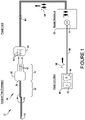
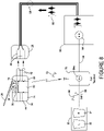
- FIGS 1 and 2a-2b illustrate a prior art system where pedal controller 90 may actuate bipolar generator 60 by means of pedal signaling 96 directed along pedal control line 98 and into control input 64.
- Left pedal 92 may be depressed to actuate a cutting mode for forceps 12, while right pedal 94 may be depressed to actuate a coagulation mode.
- a heating current 66 may be dispatched from bipolar generator 60 onto power cord 68 which may terminate in generator receptacle 28 having sockets 44.
- a power connector (not shown) on bipolar generator 60 may output the heating current 66 into a removably connectable power cord 68.
- the voltage waveform of heating current 66 may be intermittent for coagulation mode, as shown in Figure 1 , or may be continuous for cutting mode.
- Surgical tool (forceps) 12 may receive the heating current 66 through prongs 42 of tool plug 16 plugged into generator receptacle 28.
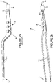
- two elongated blades 14 may be coated with an insulator or various insulation materials on all parts extending from base end 20 to heating end 18 in order to avoid a short circuit.
- the blades may be bare on the inside tips near heating end 18 for grabbing tissues to be cauterized or dissected by the passage of heating current 66.
- Heating current 66 may be an alternating current and have a frequency ranging from approximately 200 kHz to approximately 4.0 MHz.
- a handle 22 is held by a surgeon and may allow for articulation of blades 14.
- Blades 14 may be insulatively bound together by insulator 26 and may allow for articulation of blades 14. Insulator 26 may also retain prongs 42 of tool plug 16.
- Base portion 24 may refer to the portion of the tool 12 closest to tool plug 16 and which is not involved in surgical effect, and may be approximately concurrent with handle 22.
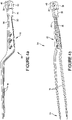
- a bipolar electrosurgical actuating system 10 comprises an actuator assembly 30 having an output receptacle 34 with sockets 44, an input plug 32 with prongs 42, and an actuating component 40 arranged to pass a heating current 66 from prongs 44 to sockets 42.
- Actuator assembly 30 may be interposed in-line between a tool plug 16 of surgical tool (forceps) 12 and a generator receptacle 28 complementary to tool plug 16, as shown in Figure 3b .
- the connector type chosen for output receptacle 34 and input plug 32 may be selected to match the size, style, and gender of the connector used by surgical tools 12 of different manufacture.
- Actuating component 40 includes a switch 36 and a lever arm 38 and is configured to communicate with bipolar generator 60 for selectively actuating the heating current 66 to flow from input plug 32 to output receptacle 34 upon engagement of the lever arm 38.
- Various means known in the art may facilitate selective actuation of bipolar generator 60 and which are described below for Figures 6-8 .
- heating current 66 passes through power cord 68 to generator receptacle 28, through actuator assembly 30, and into forceps 12 at tool plug 16. Heating current 66 may then conduct through insulator 26 to base end 30 of blades 14 for effectuating at least one of a cutting mode and a coagulation mode at heating end 18.
- Base portion 24 may refer to the portion of the forceps 12 closest to tool plug 16 and which is not involved in surgical effect, and may be approximately concurrent with handle 22.
- surgical tool 12 is a forceps and includes two elongated conducting members (blades 14) terminating in a heating end 18.
- prong 42 and socket 44 connectors may include a wire terminal, a bayonet twist mount, a flush mount with screws, locking pins with a release, a snap, and a clamp.
- the tool plug 16 and input plug 32 may be configured as female connectors and the generator receptacle and output receptacle may be configured as male connectors.
- pedal controller 90 may optionally be connected to bipolar generator 60 by pedal control line 98 for offering an additional method of selectively actuating bipolar generator 60.
- Left pedal 92 and right pedal 94 may be depressed to actuate a cutting mode or a coagulation mode, respectively.
- selective actuation of bipolar generator 60 may be accomplished by a hard electrical switch 46 included in actuating component 40 and engaged by switch 36 for directly conducting the heating current 66 from input plug 32 to output receptacle 34 ( Figure 6 ).
- selective actuation of bipolar generator 60 may be accomplished by a control circuit 70 included in actuating component 40 and generating a control signaling 72 conductively or inductively coupled by signaling tap 78 to input plug 32 for communicating with bipolar generator 60 for selectively actuating heating current 66 ( Figure 7 ).
- selective actuation of bipolar generator 60 may be accomplished by an actuator transmitter 74 included in the actuating component 40, where a control signaling 72 may be wirelessly transmitted to and receivable by the bipolar generator 60 via auxiliary receiver 76 ( Figure 8 ). Additional description for Figures 6-8 is provided below.
- lever arm 38 is hingedly moveable to engage switch 36 for selectively actuating the heating current 66.
- lever arm 38 may be hinged at one end and configured to depress a momentary push button switch 36 when lever arm 38 is moved downward and toward assembly 30.
- lever arm 38 may engage a rocker switch 36 (not shown) during a sideways movement parallel to the surface of assembly 30 and thereby actuate heating current 66.
- lever arm 38 extends over handle 22 along the sides of forceps 12 or the top or bottom of forceps 12, providing a convenient means for actuating heating current 66 using the same or opposite hand as the hand holding forceps 12.
- Lever arm 38 may be configured for operation by a human hand such that it conforms to the shape of the hand and its available range of motion to allow for a subtle and fault-free engagement without interfering with the articulation of forceps 12.
- lever arm 38 may include a lever switch mechanism (not shown) for selectively actuating the heating current 66 in response to a displacement of the lever arm 38 by at least one of the following means: mechanical actuation, electrical resistance, piezoelectric pressure, electrostatic sensing.
- the displacement may be an angular pivoting, a pistoning of the lever shaft, a rotation of the shaft, a flexing, or some other movement.
- the lever switch mechanism may provide additional control features in addition to those provided by switch 36.
- lever arm 38 may be a rod extending from a piezoelectric 'joystick' base (lever switch mechanism).
- Switch 36 may be configured as at least one of a push button, a slide switch, a rotating shaft, a joystick, an electrostatic sensor, a piezoelectric sensor, a temperature switch, a rocker switch, a momentary switch, and a voice-activated switch. Switch 36 is used in combination with lever arm 38.
- having a flexible means for interposing a switch 36 and/or lever arm 38 in-line with power cord 68 may provide a visible and/or reliably known location for selectively actuating heating current 66.
- a jumper cord 58 may connect a tool portion 86 of actuator assembly 30 to a generator portion 88 of actuator assembly 30, the tool portion 86 containing output receptacle 34 and connecting to tool plug 16, the generator portion 88 containing input plug 32 and actuating component 40 and connecting to generator receptacle 28.
- jumper cord 58 may separate and provide conduction between input plug 32 and output receptacle 34 for mounting the actuating component 40 to an operating table 100.
- lever arm 38 when positioned at operating table 100, may be engaged by a human hand or hip.
- jumper cord 58 may enable the actuating component 40 to be held by a human hand, held actuatably in a human mouth, mounted to a positioning arm, mounted actuatably to a human upper body, or mounted to another piece of operating room equipment.
- actuating component 40 may be interposed anywhere along an available current path ( Figure 10 ) concurrent with power cord 68 and extending from handle 22 of a surgical tool 12 to bipolar generator 60.
- assembly 30 may include jumper cord 58 for separating and providing conduction between actuating component 40 and input plug 32, where generator receptacle 28 may be a power connector (not shown) mounted on the bipolar generator and outputting heating current 66 into an actuator assembly that includes the power cord feature.
- generator receptacle 28 may not be complementary to tool plug 16.
- providing an in-line method for selectively actuating heating current 66 may allow actuating component 40 to be flexibly positioned for reliable access by some part of a human upper body, thereby removing the limitations and uncertainty of a pedal controller 90.
- selective actuation of bipolar generator 60 may be accomplished by hard electrical switches 46 closing a circuit between input plug 32 and output receptacle 34 for each respective conductor.
- Hard electrical switch 46 may be a single-pole-single-throw type that may be mechanically or electrically engaged by switch 36. Alternatively, one hard electrical switch 46 may close the circuit of one of two bipolar conducting paths, the other circuit being continually closed.
- a heating current 66 may be available at generator receptacle 28 at a desired preset condition, and engagement of hard electrical switch 46 may close the circuit actuating bipolar generator 60 to conduct heating current 66 to surgical tool 12.
- the engagement of hard electrical switch 46 may constitute a communication with and an actuation of bipolar generator 60.
- a surgeon may depress left pedal 92 for effectuating a cutting mode, and then engage switch 36 to pass the heating current 66 to a forceps 12 at the precise moment required.
- a precision cut may be engaged by a switch 36 or lever arm 38 located at or above a waist level and having a finer movement than a large, heavy foot pedal not visible to the surgeon.
- bipolar generator 60 may be accomplished by a hard electrical switch closing a circuit between two auxiliary wires (not shown) incorporated into power cord 68 for tripping a relay (not shown) actuating the heating current 66.
- the relay may be internal to generator 60 or may be included in an auxiliary receiver that generates a pedal signaling 96 for control input 64.
- a continuous pass-through connection may exist between input plug 32 and output receptacle 34.
- bipolar generator 60 may be accomplished by a control circuit 70 included in actuating component 40 and generating a control signaling 72 corresponding to an engagement of switch 36 or lever arm 38 and conductively or inductively coupled by signaling tap 78 to input plug 32 for communicating with bipolar generator 60 to selectively actuate heating current 66.
- Bipolar generator 60 may include an internal auxiliary receiver 76 for decoding control signaling 72.
- Receiver 76 may decode control signaling 72 into a control format similar to that of pedal signaling 96 conventionally received by pedal controller 90 for effectuating one of a cutting mode or a coagulation mode. Additionally, control signaling may effectuate an OFF mode where there is no current flow.
- a closed circuit may exist between receptacle 34 and input plug 32.
- an auxiliary receiver 76 may be external to bipolar generator 60 and may collect a sample of control signaling 72 from a coupler or inductive strap (not shown) wrapped around power cord 68. External receiver 76 may decode the control signaling 72 and may then direct the decoded output (not shown) into control input 64, thereby avoiding modifications to bipolar generator 60.
- pedal controller 90 ( Figure 3a and 8 ) may be plugged into an available control input 64 or 64a through pedal control line 98 for providing an additional means for actuating heating current 66.
- bipolar generator 60 selective actuation of bipolar generator 60 may be accomplished by an actuator transmitter 74 included in actuating component 40, where a control signaling 72 from control circuit 70 and corresponding to an engagement of switch 36 or lever arm 38 may be wirelessly transmitted to an auxiliary receiver 76 external to bipolar generator 60 .
- Auxiliary receiver 76 may then decode control signaling 72 into a suitable format (not shown) for communicating over auxiliary control line 99 into bipolar generator 60 at control input 64.
- Bipolar generator 60 may then effectuate a desired operational mode of surgical tool 12 based on the decoded output of auxiliary receiver 76.
- a closed circuit may exist between receptacle 34 and input plug 32.
- auxiliary receiver 76 may be internal to bipolar generator 60 for decoding control signaling 72 received wirelessly from actuator transmitter 74.
- pedal controller 90 may be configured to secondarily actuate a cut mode or coagulation mode through pedal control line 98 routed into external auxiliary receiver 76 at control input 64a.
- auxiliary receiver 76 may combine pedal signaling 96 and control signaling 72 for selectively actuating bipolar generator 60 via auxiliary control line 99.
- control signaling 72 may incorporate additional control beyond those effectuating modes of electrosurgery.
- control signaling may be configured for setting the voltage or duty cycle (not shown) of bipolar generator 60, and may also be configured for setting the operating conditions of other equipment in the operating room (not shown), such as by auxiliary receiver 76 receiving and routing commands directed to equipment other than bipolar generator 60.
- actuator assembly 30 may include a microphone and a voice-activated switch for selectively actuating heating current 66.
- actuator assembly 30 may include a battery (not shown) for powering control circuit 70 and actuator transmitter 74, the actuator assembly 30 being removed from interposition between tool plug 16 and generator receptacle 28 in order to operate as a remote control and configured for mounting to operating table 100.
- control circuit 70 upon engagement of lever arm 38, control circuit 70 generates control signaling 72 which is received and decoded by auxiliary receiver 76, selectively actuating bipolar generator 60 through auxiliary control line 99 and control input 64.
- heating current 66 is conducted through power cord 68, through the connector pair composed of generator receptacle 28 and tool plug 16, and to the heating end 18 of blades 14 of forceps 12.
- pedals 92 and 94 of pedal controller 90 may be depressed to send pedal signaling 96 over pedal control line 98 and into control input 64a for actuating bipolar generator 60.
- remote assembly 30 may be handheld, held actuatably in a human mouth, hingedly mounted to a shoe, mounted actuatably to a human upper body, mounted to a positioning arm, and mounted to at least one blade 14 of forceps 12.
- actuator assembly 30 may include a blade coupling element (not shown) similar to signaling tap 78 for coupling control signaling 72 of a remote control assembly 30 onto one or both blades 14 of forceps 12.
- the actuating component 40 may be disposed with a switch (not shown), a lever arm 38, a lever switch mechanism 49 (not shown) integrated into lever arm 38, or a lever arm 38 and switch 36, each permutation for effectuating an electrosurgical mode, such as coagulation.
- Input plug 32 and output receptacle 34 may be excluded from a remote control assembly or their contacts may be insulated.
- two elongated conducting members 14 extending from a base end 20 of surgical tool 12 to a heating end 18 may be configured to receive heating current 66 from the bipolar generator 60 through a power cord 68.
- the bipolar electrosurgical actuating system may include the actuating component of the actuator assembly in an integral configuration with the elongated conducting members. This integral configuration may be built into the base or blades of a bipolar forceps, which may be disposable or reusable or otherwise configured for single use or multiple uses.
- An actuator assembly 30 may be interposed along an available current path 62 extending between a handle 22 of surgical tool 12 and bipolar generator 60, the interposing resulting in, for each conductor interposed, a generator terminal 52 ( Figure 11 ) conductive to bipolar generator 60 and a tip terminal 54 ( Figure 11 ) conductive to heating end 18.
- Actuator assembly 30 may include actuating component 40 having at least one of a switch 36 and a lever arm 38 and being configured to communicate with the bipolar generator 60 to selectively actuate heating current 66 to flow from generator terminal 52 to tip terminal 54 upon engagement of the switch 36 or the lever arm 38, as described for Figures 6-8 above.
- the flow of heating current 66 may be facilitated by at least one of the following actuating steps: closing a hard electrical switch 46 in actuating component 40 ( Figure 6 ), coupling a control signaling 72 from actuating component 40 onto the available current path 62 and receivable by bipolar generator 60 ( Figures 7 , 10-11 ), and wirelessly transmitting control signaling 72 from actuating component 40 to and receivable by bipolar generator 60 ( Figure 8 ).
- actuator assembly 30 may be interposed in at least one of the elongated conducting members 14 within a base portion 24 of surgical tool 12 nearer base end 20 ( Figure 10 ).
- switch 36 may comprise a rocker switch for permanent or momentary engagement of an operational mode, such as cauterization ( Figure 10 ).
- actuating component 40 may include lever arm 38 extending over the forceps handle 22, as described for Figures 3a-3b and 4a-4b above.
- actuator assembly 30 may be interposed in power cord 68, and may couple a control signaling 72 from actuating component 40 onto the power cord 68 for receiving by bipolar generator 60 ( Figure 11 ).
- Control input 64 may be optionally utilized a by pedal controller 90 ( Figure 3a ) for actuating a heating current 66, or may be utilized by an external auxiliary receiver 76 ( Figures 8 and 9 ) for conducting decoded control signaling 72 into bipolar generator 60, thereby selecting an operational mode such as coagulation, cutting, or an off mode.
- actuator assembly 30 may interpose power cord 68 where an input plug 32 is added to generator terminal 52 for mating to the power cord and where a blade connector (not shown) is added to tool terminal 54 for clipping or sliding onto forceps blades 14.
- tool plug 16 may be bypassed or used strictly for mechanically mounting assembly 30, while heating current 66 may be routed through assembly 30 via the blade connector to blades 14 upon engagement of the switch 36 or the lever arm 38.
- assembly 30 may include a jumper cord (functioning as power cord 68) between actuating component 40 and input plug 32, the assembly plugging into a power connector (not shown) mounted on bipolar generator 60 and outputting heating current 66 for delivery to blades 14 via the blade connector described above.
- selective actuation may be accomplished by a hard electrical switch closing a circuit between two auxiliary wires (not shown) accompanying the two wires carrying heating current 66, the switch closing for tripping a relay (not shown) actuating the heating current.
- the relay may be internal to generator 60 or may be included in an auxiliary receiver that generates a pedal signaling 96 for control input 64.
- insulator 26 may insulatively bind conducting members 14 together, and may allow for their articulation by a surgeon. Additionally, insulator 26 may join power cord 68 with conducting members 14 without the use of connectors. In an embodiment, in Figure 10 , assembly 30 may be interposed on only one conducting member 14 and may acquire access to the second conductor of power cord 68 via a wire (not shown) channeled through member 14 from insulator 26, thereby completing a circuit for sending control signaling 72.
Description
- Bipolar electrosurgery, including bipolar electrocautery, is widely used to apply a heating current to a very localized volume of tissues in order to achieve hemostasis (cauterization, coagulation) or to dissect (cut) tissues, such as during neurosurgery. Typically, a bipolar generator resting near the operating table generates steady or intermittent voltages which are delivered through a power cord to a bipolar electrosurgical tool, such as a forceps. A foot pedal controller operated by the surgeon connects to the bipolar generator through a pedal control line separate from the power cord delivering the heating current to the forceps. Unfortunately, the location of the pedal controller is often not aligned with the surgeon's foot, requiring that the surgeon grope for the pedal or contort his or her body position in order to depress the correct pedal, posing significant risk and delay to the surgery in progress.
- One solution is to have a surgeon's assistant move the pedal controller to a position which is close to the surgeon's foot. But this, again, adds delay to the surgery. Further, if the surgeon moves to another standing position, the location of the pedal controller may no longer be reliably known by the surgeon. Additionally, the pedal control line is an additional cable in an operating room already full of instruments and cables, and may thereby create clutter and a risk of falling.
US5116333 ,US2176479 ,US4370980 andWO9829044 - The present invention is defined by the appended claims 1 and 8. Preferred embodiments are disclosed in the dependent claims.
- In an embodiment, there is disclosed a system for selectively actuating a heating current conductible from a bipolar generator to a surgical tool and which comprises an actuator assembly having an output receptacle, an input plug, and an actuating component. The output receptacle is configured to receive a complementary tool plug of the surgical tool. The input plug may be configured for mating with a generator receptacle receivable of the heating current from the bipolar generator. The actuating component has at least one of a switch and a lever arm and is configured to communicate with the bipolar generator for selectively actuating the heating current to flow from the input plug to the output receptacle upon engagement of the switch or the lever arm.
- In another embodiment, there is disclosed a system for selectively actuating a heating current conductible from a bipolar generator to a surgical tool, and which may comprise two elongated conducting members extending from a base end of the surgical tool to a heating end of the surgical tool. The base end may be configured to receive the heating current from the bipolar generator through a power cord. The heating end may effectuate at least one of the following modes of operation of the surgical tool: cutting, coagulation. An actuator assembly may interpose one of the power cord and at least one of the elongated conducting members within a base portion of the surgical tool nearer the base end. The interposing may result in a generator terminal conductive to the bipolar generator and a tip terminal conductive to the heating end. The actuator assembly comprises an actuating component having a switch and a lever arm and being configured to communicate with the bipolar generator to selectively actuate the heating current to flow from the generator terminal to the tip terminal upon engagement of the switch or the lever arm.
- In an example not part of the claimed invention, there is disclosed a method for selectively actuating a heating current conductible from a bipolar generator to an electrosurgical forceps, and which may comprise interposing an actuating component along an available current path extending between a handle of the forceps and the bipolar generator. The bipolar generator may be capable of delivering the heating current for effectuating at a heating end of the forceps at least one of a cutting mode and a coagulation mode. The method may further comprise disposing on the actuating component at least one of a switch and a lever arm. The method may further comprise engaging the switch or the lever arm by one of a surgeon and a surgeon's assistant, the switch or the lever arm being configured for human operation by one of a hand and an upper body. The method may further comprise the actuating component communicating with the bipolar generator to selectively actuate the heating current to flow to the heating end of the forceps upon engagement of the switch or the lever arm.
- Additional objects, advantages and novel features of the technology will be set forth in part in the description which follows, and in part will become more apparent to those skilled in the art upon examination of the following, or may be learned from practice of the technology.
- Non-limiting and non-exhaustive embodiments of the present invention, including the preferred embodiment, are described with reference to the following figures, wherein like reference numerals refer to like parts throughout the various views unless otherwise specified. Illustrative embodiments of the invention are illustrated in the drawings, in which:
-
FIGURE 1 (prior art) illustrates an embodiment of foot pedals used to initiate the flow of a heating current to electrosurgical forceps. -
FIGURES 2a-2b (prior art) illustrates an embodiment of electrosurgical forceps connected by a tool plug. -
FIGURES 3a-3b illustrate an exemplary embodiment of an in-line actuator assembly for a bipolar electrosurgical actuating system, in accordance with an embodiment of the present disclosure. -
FIGURES 4a-4b illustrate an exemplary embodiment of an actuator assembly mounted to a forceps for a bipolar electrosurgical actuating system. -
FIGURES 5a-5b illustrate an arrangement not part of the claimed invention of an in-line actuator assembly separated by a jumper cord for a bipolar electrosurgical actuating system and method. -
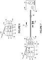
FIGURE 6 illustrates an exemplary embodiment of a hard electrical switch for facilitating an actuating component for a bipolar electrosurgical actuating system. -
FIGURE 7 illustrates an exemplary embodiment of a control signaling component coupled to the input plug for facilitating an actuating component for a bipolar electrosurgical actuating system. -
FIGURE 8 illustrates an exemplary embodiment of a control signaling transmitted to an auxiliary receiver for facilitating an actuating component for a bipolar electrosurgical actuating system. -
FIGURE 9 illustrates an arrangement not part of the claimed invention of using the actuator assembly as a remote control for a bipolar electrosurgical actuating system and method. -
FIGURE 10 illustrates an arrangement not part of the claimed invention of an actuator assembly integrated into a forceps for a bipolar electrosurgical actuating system and method. -
FIGURE 11 illustrates an arrangement not part of the claimed invention of an actuator assembly integrated into a power cord for a bipolar electrosurgical actuating system and method. - Embodiments are described more fully below in sufficient detail to enable those skilled in the art to practice the system. However, embodiments may be implemented in many different forms, within the scope of the appended claims, and should not be construed as being limited to the embodiments set forth herein. The following detailed description is, therefore, not to be taken in a limiting sense.
- When elements are referred to as being "connected" or "coupled," the elements can be directly connected or coupled together or one or more intervening elements may also be present. In contrast, when elements are referred to as being "directly connected" or "directly coupled," there are no intervening elements present.
-
Figures 1 and2a-2b illustrate a prior art system wherepedal controller 90 may actuatebipolar generator 60 by means ofpedal signaling 96 directed alongpedal control line 98 and intocontrol input 64.Left pedal 92 may be depressed to actuate a cutting mode forforceps 12, whileright pedal 94 may be depressed to actuate a coagulation mode. In response to signals onpedal control line 98, aheating current 66 may be dispatched frombipolar generator 60 ontopower cord 68 which may terminate ingenerator receptacle 28 havingsockets 44. A power connector (not shown) onbipolar generator 60 may output theheating current 66 into a removablyconnectable power cord 68. The voltage waveform ofheating current 66 may be intermittent for coagulation mode, as shown inFigure 1 , or may be continuous for cutting mode. Surgical tool (forceps) 12 may receive theheating current 66 throughprongs 42 oftool plug 16 plugged intogenerator receptacle 28. - Continuing with
Figures 1 and2a-2b , twoelongated blades 14 may be coated with an insulator or various insulation materials on all parts extending frombase end 20 to heatingend 18 in order to avoid a short circuit. However, the blades may be bare on the inside tips near heatingend 18 for grabbing tissues to be cauterized or dissected by the passage ofheating current 66. Heatingcurrent 66 may be an alternating current and have a frequency ranging from approximately 200 kHz to approximately 4.0 MHz. Ahandle 22 is held by a surgeon and may allow for articulation ofblades 14.Blades 14 may be insulatively bound together byinsulator 26 and may allow for articulation ofblades 14.Insulator 26 may also retainprongs 42 oftool plug 16.Base portion 24 may refer to the portion of thetool 12 closest totool plug 16 and which is not involved in surgical effect, and may be approximately concurrent withhandle 22. - Now referring to
Figures 3a-3b ,4a-4b ,5a-5b , and6-8 , a bipolarelectrosurgical actuating system 10 comprises anactuator assembly 30 having anoutput receptacle 34 withsockets 44, aninput plug 32 withprongs 42, and an actuatingcomponent 40 arranged to pass aheating current 66 fromprongs 44 tosockets 42.Actuator assembly 30 may be interposed in-line between atool plug 16 of surgical tool (forceps) 12 and agenerator receptacle 28 complementary totool plug 16, as shown inFigure 3b . The connector type chosen foroutput receptacle 34 andinput plug 32 may be selected to match the size, style, and gender of the connector used bysurgical tools 12 of different manufacture.Actuating component 40 includes aswitch 36 and alever arm 38 and is configured to communicate withbipolar generator 60 for selectively actuating the heating current 66 to flow from input plug 32 tooutput receptacle 34 upon engagement of thelever arm 38. Various means known in the art may facilitate selective actuation ofbipolar generator 60 and which are described below forFigures 6-8 . - Continuing, in various embodiments, heating current 66 passes through
power cord 68 togenerator receptacle 28, throughactuator assembly 30, and intoforceps 12 attool plug 16. Heating current 66 may then conduct throughinsulator 26 to base end 30 ofblades 14 for effectuating at least one of a cutting mode and a coagulation mode atheating end 18.Base portion 24 may refer to the portion of theforceps 12 closest to tool plug 16 and which is not involved in surgical effect, and may be approximately concurrent withhandle 22. Generalizing,surgical tool 12 is a forceps and includes two elongated conducting members (blades 14) terminating in aheating end 18. Alternatives to theprong 42 andsocket 44 connectors may include a wire terminal, a bayonet twist mount, a flush mount with screws, locking pins with a release, a snap, and a clamp. Alternatively, thetool plug 16 and input plug 32 may be configured as female connectors and the generator receptacle and output receptacle may be configured as male connectors. - Referring still to
Figures 3a-3b ,4a-4b ,5a-5b , and6-8 ,pedal controller 90 may optionally be connected tobipolar generator 60 bypedal control line 98 for offering an additional method of selectively actuatingbipolar generator 60.Left pedal 92 andright pedal 94 may be depressed to actuate a cutting mode or a coagulation mode, respectively. In an embodiment, selective actuation ofbipolar generator 60 may be accomplished by a hardelectrical switch 46 included inactuating component 40 and engaged byswitch 36 for directly conducting the heating current 66 from input plug 32 to output receptacle 34 (Figure 6 ). In another embodiment, selective actuation ofbipolar generator 60 may be accomplished by acontrol circuit 70 included inactuating component 40 and generating a control signaling 72 conductively or inductively coupled by signalingtap 78 to inputplug 32 for communicating withbipolar generator 60 for selectively actuating heating current 66 (Figure 7 ). In yet another embodiment, selective actuation ofbipolar generator 60 may be accomplished by anactuator transmitter 74 included in theactuating component 40, where a control signaling 72 may be wirelessly transmitted to and receivable by thebipolar generator 60 via auxiliary receiver 76 (Figure 8 ). Additional description forFigures 6-8 is provided below. - Continuing with
Figures 3a-3b ,4a-4b ,5a-5b , and6-8 ,lever arm 38 is hingedly moveable to engageswitch 36 for selectively actuating theheating current 66. For example,lever arm 38 may be hinged at one end and configured to depress a momentarypush button switch 36 whenlever arm 38 is moved downward and towardassembly 30. Alternately,lever arm 38 may engage a rocker switch 36 (not shown) during a sideways movement parallel to the surface ofassembly 30 and thereby actuate heating current 66. Referring toFigures 4a-4b , in an embodiment,lever arm 38 extends overhandle 22 along the sides offorceps 12 or the top or bottom offorceps 12, providing a convenient means for actuating heating current 66 using the same or opposite hand as thehand holding forceps 12.Lever arm 38 may be configured for operation by a human hand such that it conforms to the shape of the hand and its available range of motion to allow for a subtle and fault-free engagement without interfering with the articulation offorceps 12. - Still with
Figures 3a-3b ,4a-4b ,5a-5b , and6-8 ,lever arm 38 may include a lever switch mechanism (not shown) for selectively actuating the heating current 66 in response to a displacement of thelever arm 38 by at least one of the following means: mechanical actuation, electrical resistance, piezoelectric pressure, electrostatic sensing. The displacement may be an angular pivoting, a pistoning of the lever shaft, a rotation of the shaft, a flexing, or some other movement. The lever switch mechanism may provide additional control features in addition to those provided byswitch 36. For example,lever arm 38 may be a rod extending from a piezoelectric 'joystick' base (lever switch mechanism).Switch 36 may be configured as at least one of a push button, a slide switch, a rotating shaft, a joystick, an electrostatic sensor, a piezoelectric sensor, a temperature switch, a rocker switch, a momentary switch, and a voice-activated switch.Switch 36 is used in combination withlever arm 38. Advantageously, having a flexible means for interposing aswitch 36 and/orlever arm 38 in-line withpower cord 68 may provide a visible and/or reliably known location for selectively actuating heating current 66. - Referring now to
Figures 5a-5b , ajumper cord 58 may connect atool portion 86 ofactuator assembly 30 to agenerator portion 88 ofactuator assembly 30, thetool portion 86 containingoutput receptacle 34 and connecting to tool plug 16, thegenerator portion 88 containinginput plug 32 andactuating component 40 and connecting togenerator receptacle 28. In various embodiments,jumper cord 58 may separate and provide conduction betweeninput plug 32 andoutput receptacle 34 for mounting theactuating component 40 to an operating table 100. For example,lever arm 38, when positioned at operating table 100, may be engaged by a human hand or hip. Alternatively,jumper cord 58 may enable theactuating component 40 to be held by a human hand, held actuatably in a human mouth, mounted to a positioning arm, mounted actuatably to a human upper body, or mounted to another piece of operating room equipment. In other embodiments, actuatingcomponent 40 may be interposed anywhere along an available current path (Figure 10 ) concurrent withpower cord 68 and extending fromhandle 22 of asurgical tool 12 tobipolar generator 60. For example, in an embodiment not shown,assembly 30 may includejumper cord 58 for separating and providing conduction betweenactuating component 40 andinput plug 32, wheregenerator receptacle 28 may be a power connector (not shown) mounted on the bipolar generator and outputting heating current 66 into an actuator assembly that includes the power cord feature. In this case,generator receptacle 28 may not be complementary totool plug 16. Advantageously, providing an in-line method for selectively actuating heating current 66 may allow actuatingcomponent 40 to be flexibly positioned for reliable access by some part of a human upper body, thereby removing the limitations and uncertainty of apedal controller 90. - Referring now to
Figure 6 , in various embodiments, selective actuation ofbipolar generator 60 may be accomplished by hardelectrical switches 46 closing a circuit betweeninput plug 32 andoutput receptacle 34 for each respective conductor. Hardelectrical switch 46 may be a single-pole-single-throw type that may be mechanically or electrically engaged byswitch 36. Alternatively, one hardelectrical switch 46 may close the circuit of one of two bipolar conducting paths, the other circuit being continually closed. In an embodiment, a heating current 66 may be available atgenerator receptacle 28 at a desired preset condition, and engagement of hardelectrical switch 46 may close the circuit actuatingbipolar generator 60 to conduct heating current 66 tosurgical tool 12. In this case, the engagement of hardelectrical switch 46 may constitute a communication with and an actuation ofbipolar generator 60. For example, a surgeon may depressleft pedal 92 for effectuating a cutting mode, and then engageswitch 36 to pass the heating current 66 to aforceps 12 at the precise moment required. Advantageously, a precision cut may be engaged by aswitch 36 orlever arm 38 located at or above a waist level and having a finer movement than a large, heavy foot pedal not visible to the surgeon. - Continuing with
Figure 6 , in an embodiment not shown, selective actuation ofbipolar generator 60 may be accomplished by a hard electrical switch closing a circuit between two auxiliary wires (not shown) incorporated intopower cord 68 for tripping a relay (not shown) actuating theheating current 66. The relay may be internal togenerator 60 or may be included in an auxiliary receiver that generates a pedal signaling 96 forcontrol input 64. A continuous pass-through connection may exist betweeninput plug 32 andoutput receptacle 34. - Referring to
Figure 7 , in an embodiment, selective actuation ofbipolar generator 60 may be accomplished by acontrol circuit 70 included inactuating component 40 and generating a control signaling 72 corresponding to an engagement ofswitch 36 orlever arm 38 and conductively or inductively coupled by signalingtap 78 to inputplug 32 for communicating withbipolar generator 60 to selectively actuate heating current 66.Bipolar generator 60 may include an internalauxiliary receiver 76 for decoding control signaling 72.Receiver 76 may decode control signaling 72 into a control format similar to that of pedal signaling 96 conventionally received bypedal controller 90 for effectuating one of a cutting mode or a coagulation mode. Additionally, control signaling may effectuate an OFF mode where there is no current flow. A closed circuit may exist betweenreceptacle 34 andinput plug 32. Alternatively, in an embodiment not shown, anauxiliary receiver 76 may be external tobipolar generator 60 and may collect a sample of control signaling 72 from a coupler or inductive strap (not shown) wrapped aroundpower cord 68.External receiver 76 may decode the control signaling 72 and may then direct the decoded output (not shown) intocontrol input 64, thereby avoiding modifications tobipolar generator 60. Optionally, pedal controller 90 (Figure 3a and8 ) may be plugged into anavailable control input pedal control line 98 for providing an additional means for actuating heating current 66. - Referring to
Figure 8 , in an embodiment, selective actuation ofbipolar generator 60 may be accomplished by anactuator transmitter 74 included inactuating component 40, where a control signaling 72 fromcontrol circuit 70 and corresponding to an engagement ofswitch 36 orlever arm 38 may be wirelessly transmitted to anauxiliary receiver 76 external tobipolar generator 60 .Auxiliary receiver 76 may then decode control signaling 72 into a suitable format (not shown) for communicating overauxiliary control line 99 intobipolar generator 60 atcontrol input 64.Bipolar generator 60 may then effectuate a desired operational mode ofsurgical tool 12 based on the decoded output ofauxiliary receiver 76. A closed circuit may exist betweenreceptacle 34 andinput plug 32. Alternatively, in an embodiment not shown,auxiliary receiver 76 may be internal tobipolar generator 60 for decoding control signaling 72 received wirelessly fromactuator transmitter 74. Optionally,pedal controller 90 may be configured to secondarily actuate a cut mode or coagulation mode throughpedal control line 98 routed into externalauxiliary receiver 76 atcontrol input 64a. In an embodiment,auxiliary receiver 76 may combine pedal signaling 96 and control signaling 72 for selectively actuatingbipolar generator 60 viaauxiliary control line 99. - Referring to
Figures 7-8 , in various embodiments, control signaling 72 may incorporate additional control beyond those effectuating modes of electrosurgery. For example, control signaling may be configured for setting the voltage or duty cycle (not shown) ofbipolar generator 60, and may also be configured for setting the operating conditions of other equipment in the operating room (not shown), such as byauxiliary receiver 76 receiving and routing commands directed to equipment other thanbipolar generator 60. In other embodiments,actuator assembly 30 may include a microphone and a voice-activated switch for selectively actuating heating current 66. - Referring to
Figure 9 ,actuator assembly 30 may include a battery (not shown) for poweringcontrol circuit 70 andactuator transmitter 74, theactuator assembly 30 being removed from interposition betweentool plug 16 andgenerator receptacle 28 in order to operate as a remote control and configured for mounting to operating table 100. In an embodiment, upon engagement oflever arm 38,control circuit 70 generates control signaling 72 which is received and decoded byauxiliary receiver 76, selectively actuatingbipolar generator 60 throughauxiliary control line 99 and controlinput 64. Upon actuation ofbipolar generator 60, heating current 66 is conducted throughpower cord 68, through the connector pair composed ofgenerator receptacle 28 andtool plug 16, and to theheating end 18 ofblades 14 offorceps 12. In an embodiment,pedals pedal controller 90 may be depressed to send pedal signaling 96 overpedal control line 98 and intocontrol input 64a for actuatingbipolar generator 60. - Continuing with
Figures 9 and10 ,remote assembly 30 may be handheld, held actuatably in a human mouth, hingedly mounted to a shoe, mounted actuatably to a human upper body, mounted to a positioning arm, and mounted to at least oneblade 14 offorceps 12. In an embodiment,actuator assembly 30 may include a blade coupling element (not shown) similar to signalingtap 78 for coupling control signaling 72 of aremote control assembly 30 onto one or bothblades 14 offorceps 12. In various embodiments, the actuating component 40 (not shown) may be disposed with a switch (not shown), alever arm 38, a lever switch mechanism 49 (not shown) integrated intolever arm 38, or alever arm 38 andswitch 36, each permutation for effectuating an electrosurgical mode, such as coagulation.Input plug 32 and output receptacle 34 (not shown) may be excluded from a remote control assembly or their contacts may be insulated. - Referring now to
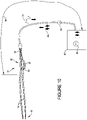
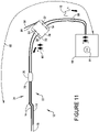
Figures 10 and11 , two elongated conductingmembers 14 extending from abase end 20 ofsurgical tool 12 to aheating end 18 may be configured to receive heating current 66 from thebipolar generator 60 through apower cord 68. The bipolar electrosurgical actuating system may include the actuating component of the actuator assembly in an integral configuration with the elongated conducting members. This integral configuration may be built into the base or blades of a bipolar forceps, which may be disposable or reusable or otherwise configured for single use or multiple uses. - There may be no connector intervening between
power cord 68 andtool 12. Anactuator assembly 30 may be interposed along an availablecurrent path 62 extending between ahandle 22 ofsurgical tool 12 andbipolar generator 60, the interposing resulting in, for each conductor interposed, a generator terminal 52 (Figure 11 ) conductive tobipolar generator 60 and a tip terminal 54 (Figure 11 ) conductive toheating end 18.Actuator assembly 30 may include actuatingcomponent 40 having at least one of aswitch 36 and alever arm 38 and being configured to communicate with thebipolar generator 60 to selectively actuate heating current 66 to flow fromgenerator terminal 52 to tip terminal 54 upon engagement of theswitch 36 or thelever arm 38, as described forFigures 6-8 above. The flow of heating current 66 may be facilitated by at least one of the following actuating steps: closing a hardelectrical switch 46 in actuating component 40 (Figure 6 ), coupling a control signaling 72 from actuatingcomponent 40 onto the availablecurrent path 62 and receivable by bipolar generator 60 (Figures 7 ,10-11 ), and wirelessly transmitting control signaling 72 from actuatingcomponent 40 to and receivable by bipolar generator 60 (Figure 8 ). - Continuing with
Figures 10 and11 ,actuator assembly 30 may be interposed in at least one of the elongated conductingmembers 14 within abase portion 24 ofsurgical tool 12 nearer base end 20 (Figure 10 ). In an embodiment, switch 36 may comprise a rocker switch for permanent or momentary engagement of an operational mode, such as cauterization (Figure 10 ). In embodiments not shown,actuating component 40 may includelever arm 38 extending over the forceps handle 22, as described forFigures 3a-3b and4a-4b above. In another embodiment,actuator assembly 30 may be interposed inpower cord 68, and may couple a control signaling 72 from actuatingcomponent 40 onto thepower cord 68 for receiving by bipolar generator 60 (Figure 11 ).Control input 64 may be optionally utilized a by pedal controller 90 (Figure 3a ) for actuating a heating current 66, or may be utilized by an external auxiliary receiver 76 (Figures 8 and9 ) for conducting decoded control signaling 72 intobipolar generator 60, thereby selecting an operational mode such as coagulation, cutting, or an off mode. - Referring still to
Figures 10 and11 , in an arrangement not shown,actuator assembly 30 may interposepower cord 68 where aninput plug 32 is added togenerator terminal 52 for mating to the power cord and where a blade connector (not shown) is added totool terminal 54 for clipping or sliding ontoforceps blades 14. In this embodiment, tool plug 16 may be bypassed or used strictly for mechanically mountingassembly 30, while heating current 66 may be routed throughassembly 30 via the blade connector toblades 14 upon engagement of theswitch 36 or thelever arm 38. In another embodiment,assembly 30 may include a jumper cord (functioning as power cord 68) betweenactuating component 40 andinput plug 32, the assembly plugging into a power connector (not shown) mounted onbipolar generator 60 and outputting heating current 66 for delivery toblades 14 via the blade connector described above. In an embodiment, selective actuation may be accomplished by a hard electrical switch closing a circuit between two auxiliary wires (not shown) accompanying the two wires carrying heating current 66, the switch closing for tripping a relay (not shown) actuating the heating current. The relay may be internal togenerator 60 or may be included in an auxiliary receiver that generates a pedal signaling 96 forcontrol input 64. - Referring to
Figures 9 and10 ,insulator 26 may insulatively bind conductingmembers 14 together, and may allow for their articulation by a surgeon. Additionally,insulator 26 may joinpower cord 68 with conductingmembers 14 without the use of connectors. In an embodiment, inFigure 10 ,assembly 30 may be interposed on only one conductingmember 14 and may acquire access to the second conductor ofpower cord 68 via a wire (not shown) channeled throughmember 14 frominsulator 26, thereby completing a circuit for sending control signaling 72. - The foregoing description of the subject matter has been presented for purposes of illustration and description. It is not intended to be exhaustive or to limit the subject matter to the precise form disclosed, and other modifications and variations may be possible in light of the above teachings within the scope of the appended claims.
Claims (12)
- An actuator assembly (30) for a bipolar electrosurgical tool, the tool comprising a forceps (12) having a handle portion (22) at a proximal region for operation of the forceps by a hand of a user, wherein the tool has a longitudinal axis extending generally between a tool plug (16) at the proximal region and at least two conducting members (14) terminating in a heating end (18) at a distal region operatively connected to the tool plug for applying to tissue electrical heating current introduced to the tool plug, the actuator assembly comprising:an actuating component (40) including a switch (36) movable between an open position and a closed position, anda connector (34) for mounting the actuator assembly on the tool in electrical connection with the tool plug and, wherein the connector is configured for connection to an electrical generating apparatus (60) to introduce electrical heating current to the tool plug when the actuator assembly is mounted on the tool and the switch is in the closed position; andan actuator arm (38) mounted to the actuating component, wherein the actuator arm is configured to extend from the actuating component generally along the longitudinal axis of the tool to a side of the handle portion, the actuator arm being spaced from the handle portion in its unactuated state when the actuator assembly is mounted on the toolcharacterized in that the actuator arm (38) is a lever arm and is configured for movement by the hand of the user relative to the actuating component to place the switch in the closed position in response to the movement of the actuator arm; and the actuator arm (38) is spaced from the actuating component (40) in its unactuated state.
- An actuator assembly as in claim 1, wherein the switch comprises a push button switch and the actuator arm is pivotally mounted to the connector for rotation by the hand of the user to depress the push button into the closed position.
- An actuator assembly as in claim 1, wherein the tool plug comprises one of a prong and a socket and the connector comprises a connector plug including the other of a mating socket and a mating prong for removably mounting the actuator assembly on the tool.
- An actuator assembly as in claim 3, wherein the tool plug comprises at least two prongs (16,42) and the connector plug comprises at least two mating sockets, wherein each prong of the tool plug is electrically connected to a respective socket of the connector plug when the actuator assembly is mounted on the tool.
- An actuator assembly as in claim 4, wherein:the forceps comprises two blades having the conducting members (14) at the distal ends thereof and the handle portion comprises facing flat regions of the blades; andthe actuator arm extends to a side of the flat region of one of the blades when the prongs on the plug are mated with the sockets on the connector.
- An actuator assembly as in claim 4, wherein:the forceps comprises two blades having the conducting members (14) at the distal ends thereof and the handle portion comprises facing flat regions of the blades; andthe actuator arm lies in a plane parallel to the longitudinal axis and extending between the flat regions of the blades when the prongs on the plug are mated with the sockets on the connector.
- An actuator assembly as in claim 1, wherein the actuating component includes another connector plug (32) for removably attaching the actuating component to a power cord (68) of the electrical generating apparatus (60).
- An electrosurgical apparatus comprising:a bipolar electrosurgical tool comprising a forceps (12) having two blades (14) including a handle portion (22) at a proximal region of the blades for operation of the forceps by a hand of a user and a longitudinal axis extending generally between a tool plug (16) at a proximal end of the blades and conducting members (14) at a distal end of the blades operatively connected to the tool plug for applying to tissue electrical heating current introduced to the tool plug as a user operates the forceps with the handle portion; andan actuator assembly (30) having (i) an actuating component (40) including a switch (36) movable between an open position and a closed position, (ii) a connector plug (34) cooperating with the tool plug to removably mount the actuator assembly on the tool in electrical connection with the tool plug, wherein the connector plug (34) is configured for connection to an electrical generating apparatus (60) to introduce electrical heating current to the tool plug when the switch is in the closed position, and (iii) an actuator arm (38) mounted to the actuating component, wherein the actuator arm extends from the actuating component generally along the longitudinal axis of the tool to a side of the handle portion, the actuator arm being spaced from the handle portion in its unactuated state,characterized in that wherein the actuator arm (38) is a lever arm and is configured for movement by the hand of the user relative to the actuating component to place the switch in the closed position in response to the movement of the actuator arm, and wherein the actuator arm (38) is spaced from the actuating component (40) in its unactuated state.
- An electrosurgical apparatus as in claim 8, wherein the switch comprises a push button switch and the actuator arm is pivotally mounted to the connector for rotation by the hand of the user to depress the push button into the closed position.
- An electrosurgical apparatus as in claim 8, wherein the handle portion comprises facing flat regions of the blades (22) and the actuator arm extends to a side of the flat region of one of the blades.
- An actuator assembly as in claim 1, wherein the actuator arm (38) is spaced from the actuating component (40) in the direction of movement.
- An electrosurgical apparatus as in claim 8, wherein the actuator arm (38) is spaced from the actuating component (40) in the direction of movement.
Applications Claiming Priority (2)
| Application Number | Priority Date | Filing Date | Title |
|---|---|---|---|
| US201462005290P | 2014-05-30 | 2014-05-30 | |
| PCT/US2015/033429 WO2015184424A1 (en) | 2014-05-30 | 2015-05-30 | Bipolar electrosurgery actuator |
Publications (3)
| Publication Number | Publication Date |
|---|---|
| EP3148466A1 EP3148466A1 (en) | 2017-04-05 |
| EP3148466A4 EP3148466A4 (en) | 2018-01-24 |
| EP3148466B1 true EP3148466B1 (en) | 2022-07-27 |
Family
ID=54699952
Family Applications (1)
| Application Number | Title | Priority Date | Filing Date |
|---|---|---|---|
| EP15798750.4A Active EP3148466B1 (en) | 2014-05-30 | 2015-05-30 | Bipolar electrosurgery actuator |
Country Status (7)
| Country | Link |
|---|---|
| US (3) | US9433460B2 (en) |
| EP (1) | EP3148466B1 (en) |
| JP (1) | JP6685289B2 (en) |
| CN (2) | CN106413614B (en) |
| AU (1) | AU2015266597B2 (en) |
| RU (1) | RU2709679C2 (en) |
| WO (1) | WO2015184424A1 (en) |
Families Citing this family (15)
| Publication number | Priority date | Publication date | Assignee | Title |
|---|---|---|---|---|
| WO2015184424A1 (en) | 2014-05-30 | 2015-12-03 | Bipad, Llc | Bipolar electrosurgery actuator |
| US10117704B2 (en) * | 2014-08-27 | 2018-11-06 | Covidien Lp | Energy-activation mechanisms for surgical instruments |
| USD778442S1 (en) * | 2015-11-19 | 2017-02-07 | Bipad, Llc | Bipolar electrosurgery actuator system |
| US11129633B2 (en) | 2016-06-24 | 2021-09-28 | Gyrus Acmi, Inc. | Medical device interface |
| US10646268B2 (en) | 2016-08-26 | 2020-05-12 | Bipad, Inc. | Ergonomic actuator for electrosurgical tool |
| CN107049480A (en) * | 2017-06-02 | 2017-08-18 | 黄盛� | A kind of general diathermy forceps adapter of American-European mark |
| WO2020154036A1 (en) | 2019-01-22 | 2020-07-30 | Bipad, Inc. | Removable integrated actuator assembly for electrosurgical forceps |
| JP6754144B2 (en) | 2019-03-01 | 2020-09-09 | リバーフィールド株式会社 | Surgical support robot |
| KR102020179B1 (en) * | 2019-04-09 | 2019-11-05 | 최보환 | Electrode for electrosurgical handpiece |
| KR102021266B1 (en) * | 2019-04-12 | 2019-09-16 | 최보환 | Electrogurgical handpiece |
| US11452559B2 (en) * | 2019-06-25 | 2022-09-27 | Covidien Lp | Electrosurgical plug for energy activation of surgical instruments |
| US11504179B2 (en) * | 2019-06-25 | 2022-11-22 | Covidien Lp | Electrosurgical plug for energy activation of surgical instruments |
| US11918272B2 (en) * | 2020-03-20 | 2024-03-05 | Billings Clinic | Wirelessly controlled bipolar surgical cautery apparatus |
| KR102445739B1 (en) * | 2020-09-22 | 2022-09-21 | 최인상 | Electrode for electrosurgical handpiece |
| KR102642223B1 (en) * | 2021-05-21 | 2024-02-28 | 최인상 | Electrode for electrosurgical handpiece |
Citations (3)
| Publication number | Priority date | Publication date | Assignee | Title |
|---|---|---|---|---|
| FR2668918A1 (en) * | 1990-11-12 | 1992-05-15 | Boudouris Odysseas | Clamp for coagulation with incorporated irrigation system |
| WO1998006338A2 (en) * | 1996-08-15 | 1998-02-19 | Stryker Corporation | Integrated system for powered surgical tools |
| WO2015143104A1 (en) * | 2014-03-20 | 2015-09-24 | Stryker Corporation | Surgical tool with ambidextrous safety switch |
Family Cites Families (66)
| Publication number | Priority date | Publication date | Assignee | Title |
|---|---|---|---|---|
| US2176479A (en) | 1937-03-20 | 1939-10-17 | David A Willis | Apparatus for finding and removing metal particles from human and animal bodies |
| US4370980A (en) * | 1981-03-11 | 1983-02-01 | Lottick Edward A | Electrocautery hemostat |
| CA1192465A (en) | 1981-03-11 | 1985-08-27 | Edward A. Lottick | Removable switch electrocautery instruments |
| US5151102A (en) * | 1989-05-31 | 1992-09-29 | Kyocera Corporation | Blood vessel coagulation/stanching device |
| US5282799A (en) * | 1990-08-24 | 1994-02-01 | Everest Medical Corporation | Bipolar electrosurgical scalpel with paired loop electrodes |
| US5116333A (en) | 1990-11-02 | 1992-05-26 | Kirwan Surgical Products, Inc. | Bipolar handswitch adapter |
| US5472442A (en) * | 1994-03-23 | 1995-12-05 | Valleylab Inc. | Moveable switchable electrosurgical handpiece |
| US6646541B1 (en) | 1996-06-24 | 2003-11-11 | Computer Motion, Inc. | General purpose distributed operating room control system |
| GB9425781D0 (en) * | 1994-12-21 | 1995-02-22 | Gyrus Medical Ltd | Electrosurgical instrument |
| US6106524A (en) * | 1995-03-03 | 2000-08-22 | Neothermia Corporation | Methods and apparatus for therapeutic cauterization of predetermined volumes of biological tissue |
| US5634924A (en) | 1995-08-28 | 1997-06-03 | Symbiosis Corporation | Bipolar roller electrodes and electrocautery probes for use with a resectoscope |
| CA2216727A1 (en) | 1996-10-02 | 1998-04-02 | Bristol-Myers Squibb Company | Autoclavable remote hand control |
| US5891140A (en) | 1996-12-23 | 1999-04-06 | Cardiothoracic Systems, Inc. | Electrosurgical device for harvesting a vessel especially the internal mammary artery for coronary artery bypass grafting |
| US6113596A (en) * | 1996-12-30 | 2000-09-05 | Enable Medical Corporation | Combination monopolar-bipolar electrosurgical instrument system, instrument and cable |
| US7534243B1 (en) | 1998-08-12 | 2009-05-19 | Maquet Cardiovascular Llc | Dissection and welding of tissue |
| US7695470B1 (en) | 1998-08-12 | 2010-04-13 | Maquet Cardiovascular Llc | Integrated vessel ligator and transector |
| US6235027B1 (en) | 1999-01-21 | 2001-05-22 | Garrett D. Herzon | Thermal cautery surgical forceps |
| US6362445B1 (en) * | 2000-01-03 | 2002-03-26 | Eaton Corporation | Modular, miniaturized switchgear |
| AU2002239709B2 (en) | 2000-12-21 | 2007-02-15 | Insulet Corporation | Medical apparatus remote control and method |
| US6569163B2 (en) | 2001-03-09 | 2003-05-27 | Quantumcor, Inc. | Wireless electrosurgical adapter unit and methods thereof |
| US6551312B2 (en) * | 2001-03-09 | 2003-04-22 | Quantum Cor, Inc. | Wireless electrosurgical device and methods thereof |
| WO2002071965A1 (en) * | 2001-03-12 | 2002-09-19 | 7Med Industrie S.A. | Single-use electronic surgical knife handle |
| US6695837B2 (en) | 2002-03-13 | 2004-02-24 | Starion Instruments Corporation | Power supply for identification and control of electrical surgical tools |
| US6747218B2 (en) | 2002-09-20 | 2004-06-08 | Sherwood Services Ag | Electrosurgical haptic switch including snap dome and printed circuit stepped contact array |
| EP1949867B1 (en) | 2003-02-20 | 2013-07-31 | Covidien AG | Motion detector for controlling electrosurgical output |
| US9035741B2 (en) | 2003-06-27 | 2015-05-19 | Stryker Corporation | Foot-operated control console for wirelessly controlling medical devices |
| JP4391788B2 (en) * | 2003-10-03 | 2009-12-24 | オリンパス株式会社 | Medical system control device |
| US10105140B2 (en) | 2009-11-20 | 2018-10-23 | Covidien Lp | Surgical console and hand-held surgical device |
| US10588629B2 (en) | 2009-11-20 | 2020-03-17 | Covidien Lp | Surgical console and hand-held surgical device |
| WO2005107857A2 (en) | 2004-05-05 | 2005-11-17 | Stryker Instruments | System and method for controlling rf output |
| KR101215233B1 (en) | 2004-11-01 | 2012-12-24 | 스트리커 코포레이션 | Secure transmission of wireless control to central unit |
| DE102005024221B4 (en) * | 2005-05-25 | 2009-10-08 | Erbe Elektromedizin Gmbh | rocker |
| DE102006042985A1 (en) * | 2005-10-04 | 2007-04-19 | Erbe Elektromedizin Gmbh | Electrosurgical instrument for coagulating tissue, has deformable unit arranged on branch or gripping device such that area of gripping device can be moved to actuate switching device when branches are closed and minimum distance is reached |
| US20070156134A1 (en) * | 2005-12-29 | 2007-07-05 | Boston Scientific Scimed, Inc. | Liquid delivery apparatus for tissue ablation |
| US8241282B2 (en) | 2006-01-24 | 2012-08-14 | Tyco Healthcare Group Lp | Vessel sealing cutting assemblies |
| EP2057955A4 (en) | 2006-06-15 | 2016-04-20 | Yanchers Inc | Remote control system |
| US8652120B2 (en) | 2007-01-10 | 2014-02-18 | Ethicon Endo-Surgery, Inc. | Surgical instrument with wireless communication between control unit and sensor transponders |
| US8684253B2 (en) | 2007-01-10 | 2014-04-01 | Ethicon Endo-Surgery, Inc. | Surgical instrument with wireless communication between a control unit of a robotic system and remote sensor |
| US8534528B2 (en) | 2007-06-04 | 2013-09-17 | Ethicon Endo-Surgery, Inc. | Surgical instrument having a multiple rate directional switching mechanism |
| US8638191B2 (en) | 2007-09-28 | 2014-01-28 | Stryker Corporation | Wireless hand-control of device by means of wireless button |
| US8622274B2 (en) | 2008-02-14 | 2014-01-07 | Ethicon Endo-Surgery, Inc. | Motorized cutting and fastening instrument having control circuit for optimizing battery usage |
| JP4826596B2 (en) | 2008-03-18 | 2011-11-30 | 株式会社デンソー | Internal combustion engine abnormality diagnosis device and abnormality diagnosis method using the same |
| CA3161692A1 (en) * | 2008-03-31 | 2009-10-08 | Applied Medical Resources Corporation | Electrosurgical system |
| AU2009244445B8 (en) * | 2008-05-05 | 2014-12-18 | Stryker Corporation | A powered surgical tool system and control console |
| DE102008037312B3 (en) * | 2008-08-11 | 2010-02-18 | Emz-Hanauer Gmbh & Co. Kgaa | Electric switch, especially in microswitch design |
| US8747400B2 (en) | 2008-08-13 | 2014-06-10 | Arthrocare Corporation | Systems and methods for screen electrode securement |
| US8133219B2 (en) | 2008-10-07 | 2012-03-13 | Olympus Medical Systems Corp. | High frequency operation apparatus and high frequency operation method |
| CA2741732C (en) | 2008-11-21 | 2016-05-17 | Stryker Corporation | Wireless operating room communication system including video output device and video display |
| US8120301B2 (en) | 2009-03-09 | 2012-02-21 | Intuitive Surgical Operations, Inc. | Ergonomic surgeon control console in robotic surgical systems |
| EP2456516B1 (en) | 2009-07-21 | 2022-10-05 | Cardiac Lead Technologies, LLC | Magnetic switching device with a switch formed by an electrocautery pen |
| JP2013503723A (en) * | 2009-09-08 | 2013-02-04 | サリエント・サージカル・テクノロジーズ・インコーポレーテッド | Cartridge assembly for electrosurgical devices, electrosurgical units, and methods of use thereof |
| US8568400B2 (en) | 2009-09-23 | 2013-10-29 | Covidien Lp | Methods and apparatus for smart handset design in surgical instruments |
| US8834518B2 (en) * | 2010-04-12 | 2014-09-16 | Ethicon Endo-Surgery, Inc. | Electrosurgical cutting and sealing instruments with cam-actuated jaws |
| US8906012B2 (en) * | 2010-06-30 | 2014-12-09 | Medtronic Advanced Energy Llc | Electrosurgical devices with wire electrode |
| US20120029498A1 (en) * | 2010-07-30 | 2012-02-02 | Daniel Igor Branovan | Bipolar Radio Frequency Ablation Instrument |
| US9345534B2 (en) * | 2010-10-04 | 2016-05-24 | Covidien Lp | Vessel sealing instrument |
| US9655672B2 (en) * | 2010-10-04 | 2017-05-23 | Covidien Lp | Vessel sealing instrument |
| US9782214B2 (en) | 2010-11-05 | 2017-10-10 | Ethicon Llc | Surgical instrument with sensor and powered control |
| US8945122B2 (en) * | 2010-11-16 | 2015-02-03 | Covidien Lp | Power glove |
| US9937002B2 (en) * | 2011-03-08 | 2018-04-10 | Nexus Control Systems, Llc | Ablation catheter system with safety features |
| US20130041292A1 (en) | 2011-08-09 | 2013-02-14 | Tyco Healthcare Group Lp | Customizable Haptic Assisted Robot Procedure System with Catalog of Specialized Diagnostic Tips |
| EP2945557B1 (en) | 2013-03-15 | 2017-01-11 | Gyrus Acmi, Inc. | Combination electrosurgical device |
| US20140336634A1 (en) | 2013-05-13 | 2014-11-13 | New Wave Surgical Corp. | Multifunctional attachment for electrocautery surgical device |
| US9675374B2 (en) | 2014-03-24 | 2017-06-13 | Ethicon Llc | Ultrasonic forceps |
| WO2015184424A1 (en) | 2014-05-30 | 2015-12-03 | Bipad, Llc | Bipolar electrosurgery actuator |
| US10646268B2 (en) | 2016-08-26 | 2020-05-12 | Bipad, Inc. | Ergonomic actuator for electrosurgical tool |
-
2015
- 2015-05-30 WO PCT/US2015/033429 patent/WO2015184424A1/en active Application Filing
- 2015-05-30 EP EP15798750.4A patent/EP3148466B1/en active Active
- 2015-05-30 CN CN201580028967.3A patent/CN106413614B/en active Active
- 2015-05-30 RU RU2016150485A patent/RU2709679C2/en active
- 2015-05-30 US US14/726,490 patent/US9433460B2/en active Active
- 2015-05-30 CN CN202110321316.0A patent/CN113069202A/en active Pending
- 2015-05-30 JP JP2017515040A patent/JP6685289B2/en active Active
- 2015-05-30 AU AU2015266597A patent/AU2015266597B2/en not_active Ceased
-
2016
- 2016-05-09 US US15/150,155 patent/US10456192B2/en active Active
-
2019
- 2019-10-01 US US16/589,568 patent/US20200163711A1/en not_active Abandoned
Patent Citations (3)
| Publication number | Priority date | Publication date | Assignee | Title |
|---|---|---|---|---|
| FR2668918A1 (en) * | 1990-11-12 | 1992-05-15 | Boudouris Odysseas | Clamp for coagulation with incorporated irrigation system |
| WO1998006338A2 (en) * | 1996-08-15 | 1998-02-19 | Stryker Corporation | Integrated system for powered surgical tools |
| WO2015143104A1 (en) * | 2014-03-20 | 2015-09-24 | Stryker Corporation | Surgical tool with ambidextrous safety switch |
Also Published As
| Publication number | Publication date |
|---|---|
| AU2015266597A1 (en) | 2017-01-12 |
| AU2015266597B2 (en) | 2019-12-19 |
| CN113069202A (en) | 2021-07-06 |
| US20150342667A1 (en) | 2015-12-03 |
| US9433460B2 (en) | 2016-09-06 |
| CN106413614B (en) | 2021-04-16 |
| US20200163711A1 (en) | 2020-05-28 |
| JP6685289B2 (en) | 2020-04-22 |
| EP3148466A1 (en) | 2017-04-05 |
| CN106413614A (en) | 2017-02-15 |
| US10456192B2 (en) | 2019-10-29 |
| JP2017516628A (en) | 2017-06-22 |
| RU2016150485A3 (en) | 2019-03-13 |
| EP3148466A4 (en) | 2018-01-24 |
| RU2709679C2 (en) | 2019-12-19 |
| US20160249973A1 (en) | 2016-09-01 |
| RU2016150485A (en) | 2018-07-04 |
| WO2015184424A1 (en) | 2015-12-03 |
Similar Documents
| Publication | Publication Date | Title |
|---|---|---|
| EP3148466B1 (en) | Bipolar electrosurgery actuator | |
| US8012154B2 (en) | Modular electrosurgical adaptors and multi function active shafts for use in electrosurgical instruments | |
| US10646268B2 (en) | Ergonomic actuator for electrosurgical tool | |
| EP2974682B1 (en) | Combination electrosurgical device | |
| EP2967741B1 (en) | Combination electrosurgical device | |
| US10231772B2 (en) | Wire retention unit for a surgical instrument | |
| EP1757242B1 (en) | Ultrasonic tool | |
| CN105208956A (en) | Combination electrosurgical device | |
| WO2010101897A1 (en) | Surgical apparatus for tissue sealing and cutting | |
| JP2017516628A5 (en) | ||
| JP6836859B2 (en) | Coagulation and incision device with improved control | |
| EP2870938B1 (en) | Treatment instrument using ultrasonic vibrations | |
| JP6574069B2 (en) | Disengagement mechanism for electrosurgical forceps | |
| CN102083385A (en) | Electrosurgical device comprising a safety unit | |
| CN106456201B (en) | forceps device and surgical system | |
| EP4108189A1 (en) | Energy based surgical instruments and systems | |
| JPH09327465A (en) | Cord and circuit for manual switch | |
| KR20210119464A (en) | Removable Integrated Actuator Assembly for Electric Surgical Forceps |
Legal Events
| Date | Code | Title | Description |
|---|---|---|---|
| STAA | Information on the status of an ep patent application or granted ep patent |
Free format text: STATUS: THE INTERNATIONAL PUBLICATION HAS BEEN MADE |
|
| PUAI | Public reference made under article 153(3) epc to a published international application that has entered the european phase |
Free format text: ORIGINAL CODE: 0009012 |
|
| STAA | Information on the status of an ep patent application or granted ep patent |
Free format text: STATUS: REQUEST FOR EXAMINATION WAS MADE |
|
| 17P | Request for examination filed |
Effective date: 20161223 |
|
| AK | Designated contracting states |
Kind code of ref document: A1 Designated state(s): AL AT BE BG CH CY CZ DE DK EE ES FI FR GB GR HR HU IE IS IT LI LT LU LV MC MK MT NL NO PL PT RO RS SE SI SK SM TR |
|
| AX | Request for extension of the european patent |
Extension state: BA ME |
|
| DAV | Request for validation of the european patent (deleted) | ||
| A4 | Supplementary search report drawn up and despatched |
Effective date: 20180102 |
|
| RIC1 | Information provided on ipc code assigned before grant |
Ipc: A61B 18/14 20060101AFI20171219BHEP |
|
| RAP1 | Party data changed (applicant data changed or rights of an application transferred) |
Owner name: BIPAD, INC. |
|
| GRAP | Despatch of communication of intention to grant a patent |
Free format text: ORIGINAL CODE: EPIDOSNIGR1 |
|
| STAA | Information on the status of an ep patent application or granted ep patent |
Free format text: STATUS: GRANT OF PATENT IS INTENDED |
|
| RIC1 | Information provided on ipc code assigned before grant |
Ipc: A61B 18/12 20060101AFI20210623BHEP Ipc: A61B 18/14 20060101ALI20210623BHEP |
|
| INTG | Intention to grant announced |
Effective date: 20210716 |
|
| GRAJ | Information related to disapproval of communication of intention to grant by the applicant or resumption of examination proceedings by the epo deleted |
Free format text: ORIGINAL CODE: EPIDOSDIGR1 |
|
| STAA | Information on the status of an ep patent application or granted ep patent |
Free format text: STATUS: REQUEST FOR EXAMINATION WAS MADE |
|
| INTC | Intention to grant announced (deleted) | ||
| GRAP | Despatch of communication of intention to grant a patent |
Free format text: ORIGINAL CODE: EPIDOSNIGR1 |
|
| STAA | Information on the status of an ep patent application or granted ep patent |
Free format text: STATUS: GRANT OF PATENT IS INTENDED |
|
| INTG | Intention to grant announced |
Effective date: 20220216 |
|
| GRAS | Grant fee paid |
Free format text: ORIGINAL CODE: EPIDOSNIGR3 |
|
| GRAA | (expected) grant |
Free format text: ORIGINAL CODE: 0009210 |
|
| STAA | Information on the status of an ep patent application or granted ep patent |
Free format text: STATUS: THE PATENT HAS BEEN GRANTED |
|
| AK | Designated contracting states |
Kind code of ref document: B1 Designated state(s): AL AT BE BG CH CY CZ DE DK EE ES FI FR GB GR HR HU IE IS IT LI LT LU LV MC MK MT NL NO PL PT RO RS SE SI SK SM TR |
|
| REG | Reference to a national code |
Ref country code: CH Ref legal event code: EP |
|
| REG | Reference to a national code |
Ref country code: AT Ref legal event code: REF Ref document number: 1506551 Country of ref document: AT Kind code of ref document: T Effective date: 20220815 |
|
| REG | Reference to a national code |
Ref country code: DE Ref legal event code: R096 Ref document number: 602015080061 Country of ref document: DE |
|
| REG | Reference to a national code |
Ref country code: IE Ref legal event code: FG4D |
|
| REG | Reference to a national code |
Ref country code: LT Ref legal event code: MG9D |
|
| REG | Reference to a national code |
Ref country code: NL Ref legal event code: MP Effective date: 20220727 |
|
| PG25 | Lapsed in a contracting state [announced via postgrant information from national office to epo] |
Ref country code: SE Free format text: LAPSE BECAUSE OF FAILURE TO SUBMIT A TRANSLATION OF THE DESCRIPTION OR TO PAY THE FEE WITHIN THE PRESCRIBED TIME-LIMIT Effective date: 20220727 Ref country code: RS Free format text: LAPSE BECAUSE OF FAILURE TO SUBMIT A TRANSLATION OF THE DESCRIPTION OR TO PAY THE FEE WITHIN THE PRESCRIBED TIME-LIMIT Effective date: 20220727 Ref country code: PT Free format text: LAPSE BECAUSE OF FAILURE TO SUBMIT A TRANSLATION OF THE DESCRIPTION OR TO PAY THE FEE WITHIN THE PRESCRIBED TIME-LIMIT Effective date: 20221128 Ref country code: NO Free format text: LAPSE BECAUSE OF FAILURE TO SUBMIT A TRANSLATION OF THE DESCRIPTION OR TO PAY THE FEE WITHIN THE PRESCRIBED TIME-LIMIT Effective date: 20221027 Ref country code: NL Free format text: LAPSE BECAUSE OF FAILURE TO SUBMIT A TRANSLATION OF THE DESCRIPTION OR TO PAY THE FEE WITHIN THE PRESCRIBED TIME-LIMIT Effective date: 20220727 Ref country code: LV Free format text: LAPSE BECAUSE OF FAILURE TO SUBMIT A TRANSLATION OF THE DESCRIPTION OR TO PAY THE FEE WITHIN THE PRESCRIBED TIME-LIMIT Effective date: 20220727 Ref country code: LT Free format text: LAPSE BECAUSE OF FAILURE TO SUBMIT A TRANSLATION OF THE DESCRIPTION OR TO PAY THE FEE WITHIN THE PRESCRIBED TIME-LIMIT Effective date: 20220727 Ref country code: FI Free format text: LAPSE BECAUSE OF FAILURE TO SUBMIT A TRANSLATION OF THE DESCRIPTION OR TO PAY THE FEE WITHIN THE PRESCRIBED TIME-LIMIT Effective date: 20220727 Ref country code: ES Free format text: LAPSE BECAUSE OF FAILURE TO SUBMIT A TRANSLATION OF THE DESCRIPTION OR TO PAY THE FEE WITHIN THE PRESCRIBED TIME-LIMIT Effective date: 20220727 |
|
| REG | Reference to a national code |
Ref country code: AT Ref legal event code: MK05 Ref document number: 1506551 Country of ref document: AT Kind code of ref document: T Effective date: 20220727 |
|
| PG25 | Lapsed in a contracting state [announced via postgrant information from national office to epo] |
Ref country code: PL Free format text: LAPSE BECAUSE OF FAILURE TO SUBMIT A TRANSLATION OF THE DESCRIPTION OR TO PAY THE FEE WITHIN THE PRESCRIBED TIME-LIMIT Effective date: 20220727 Ref country code: IS Free format text: LAPSE BECAUSE OF FAILURE TO SUBMIT A TRANSLATION OF THE DESCRIPTION OR TO PAY THE FEE WITHIN THE PRESCRIBED TIME-LIMIT Effective date: 20221127 Ref country code: HR Free format text: LAPSE BECAUSE OF FAILURE TO SUBMIT A TRANSLATION OF THE DESCRIPTION OR TO PAY THE FEE WITHIN THE PRESCRIBED TIME-LIMIT Effective date: 20220727 Ref country code: GR Free format text: LAPSE BECAUSE OF FAILURE TO SUBMIT A TRANSLATION OF THE DESCRIPTION OR TO PAY THE FEE WITHIN THE PRESCRIBED TIME-LIMIT Effective date: 20221028 |
|
| PG25 | Lapsed in a contracting state [announced via postgrant information from national office to epo] |
Ref country code: SM Free format text: LAPSE BECAUSE OF FAILURE TO SUBMIT A TRANSLATION OF THE DESCRIPTION OR TO PAY THE FEE WITHIN THE PRESCRIBED TIME-LIMIT Effective date: 20220727 Ref country code: RO Free format text: LAPSE BECAUSE OF FAILURE TO SUBMIT A TRANSLATION OF THE DESCRIPTION OR TO PAY THE FEE WITHIN THE PRESCRIBED TIME-LIMIT Effective date: 20220727 Ref country code: DK Free format text: LAPSE BECAUSE OF FAILURE TO SUBMIT A TRANSLATION OF THE DESCRIPTION OR TO PAY THE FEE WITHIN THE PRESCRIBED TIME-LIMIT Effective date: 20220727 Ref country code: CZ Free format text: LAPSE BECAUSE OF FAILURE TO SUBMIT A TRANSLATION OF THE DESCRIPTION OR TO PAY THE FEE WITHIN THE PRESCRIBED TIME-LIMIT Effective date: 20220727 Ref country code: AT Free format text: LAPSE BECAUSE OF FAILURE TO SUBMIT A TRANSLATION OF THE DESCRIPTION OR TO PAY THE FEE WITHIN THE PRESCRIBED TIME-LIMIT Effective date: 20220727 |
|
| REG | Reference to a national code |
Ref country code: DE Ref legal event code: R097 Ref document number: 602015080061 Country of ref document: DE |
|
| PG25 | Lapsed in a contracting state [announced via postgrant information from national office to epo] |
Ref country code: SK Free format text: LAPSE BECAUSE OF FAILURE TO SUBMIT A TRANSLATION OF THE DESCRIPTION OR TO PAY THE FEE WITHIN THE PRESCRIBED TIME-LIMIT Effective date: 20220727 Ref country code: EE Free format text: LAPSE BECAUSE OF FAILURE TO SUBMIT A TRANSLATION OF THE DESCRIPTION OR TO PAY THE FEE WITHIN THE PRESCRIBED TIME-LIMIT Effective date: 20220727 |
|
| PLBE | No opposition filed within time limit |
Free format text: ORIGINAL CODE: 0009261 |
|
| STAA | Information on the status of an ep patent application or granted ep patent |
Free format text: STATUS: NO OPPOSITION FILED WITHIN TIME LIMIT |
|
| PG25 | Lapsed in a contracting state [announced via postgrant information from national office to epo] |
Ref country code: AL Free format text: LAPSE BECAUSE OF FAILURE TO SUBMIT A TRANSLATION OF THE DESCRIPTION OR TO PAY THE FEE WITHIN THE PRESCRIBED TIME-LIMIT Effective date: 20220727 |
|
| 26N | No opposition filed |
Effective date: 20230502 |
|
| PG25 | Lapsed in a contracting state [announced via postgrant information from national office to epo] |
Ref country code: SI Free format text: LAPSE BECAUSE OF FAILURE TO SUBMIT A TRANSLATION OF THE DESCRIPTION OR TO PAY THE FEE WITHIN THE PRESCRIBED TIME-LIMIT Effective date: 20220727 |
|
| REG | Reference to a national code |
Ref country code: CH Ref legal event code: PL |
|
| PG25 | Lapsed in a contracting state [announced via postgrant information from national office to epo] |
Ref country code: MC Free format text: LAPSE BECAUSE OF FAILURE TO SUBMIT A TRANSLATION OF THE DESCRIPTION OR TO PAY THE FEE WITHIN THE PRESCRIBED TIME-LIMIT Effective date: 20220727 |
|
| PGFP | Annual fee paid to national office [announced via postgrant information from national office to epo] |
Ref country code: GB Payment date: 20231128 Year of fee payment: 9 |
|
| REG | Reference to a national code |
Ref country code: BE Ref legal event code: MM Effective date: 20230531 |
|
| PG25 | Lapsed in a contracting state [announced via postgrant information from national office to epo] |
Ref country code: MC Free format text: LAPSE BECAUSE OF FAILURE TO SUBMIT A TRANSLATION OF THE DESCRIPTION OR TO PAY THE FEE WITHIN THE PRESCRIBED TIME-LIMIT Effective date: 20220727 Ref country code: LU Free format text: LAPSE BECAUSE OF NON-PAYMENT OF DUE FEES Effective date: 20230530 Ref country code: LI Free format text: LAPSE BECAUSE OF NON-PAYMENT OF DUE FEES Effective date: 20230531 Ref country code: CH Free format text: LAPSE BECAUSE OF NON-PAYMENT OF DUE FEES Effective date: 20230531 |
|
| PGFP | Annual fee paid to national office [announced via postgrant information from national office to epo] |
Ref country code: FR Payment date: 20231128 Year of fee payment: 9 Ref country code: DE Payment date: 20231128 Year of fee payment: 9 |
|
| REG | Reference to a national code |
Ref country code: IE Ref legal event code: MM4A |
|
| PG25 | Lapsed in a contracting state [announced via postgrant information from national office to epo] |
Ref country code: IE Free format text: LAPSE BECAUSE OF NON-PAYMENT OF DUE FEES Effective date: 20230530 |