EP3148462B1 - Bone fixation assembly - Google Patents
Bone fixation assembly Download PDFInfo
- Publication number
- EP3148462B1 EP3148462B1 EP15723087.1A EP15723087A EP3148462B1 EP 3148462 B1 EP3148462 B1 EP 3148462B1 EP 15723087 A EP15723087 A EP 15723087A EP 3148462 B1 EP3148462 B1 EP 3148462B1
- Authority
- EP
- European Patent Office
- Prior art keywords
- bone fixation
- actuator
- traveler
- tension
- fixation instrument
- Prior art date
- Legal status (The legal status is an assumption and is not a legal conclusion. Google has not performed a legal analysis and makes no representation as to the accuracy of the status listed.)
- Not-in-force
Links
Images


Classifications
-
- A—HUMAN NECESSITIES
- A61—MEDICAL OR VETERINARY SCIENCE; HYGIENE
- A61B—DIAGNOSIS; SURGERY; IDENTIFICATION
- A61B17/00—Surgical instruments, devices or methods, e.g. tourniquets
- A61B17/56—Surgical instruments or methods for treatment of bones or joints; Devices specially adapted therefor
- A61B17/58—Surgical instruments or methods for treatment of bones or joints; Devices specially adapted therefor for osteosynthesis, e.g. bone plates, screws, setting implements or the like
- A61B17/88—Osteosynthesis instruments; Methods or means for implanting or extracting internal or external fixation devices
- A61B17/8861—Apparatus for manipulating flexible wires or straps
-
- A—HUMAN NECESSITIES
- A61—MEDICAL OR VETERINARY SCIENCE; HYGIENE
- A61B—DIAGNOSIS; SURGERY; IDENTIFICATION
- A61B17/00—Surgical instruments, devices or methods, e.g. tourniquets
- A61B17/56—Surgical instruments or methods for treatment of bones or joints; Devices specially adapted therefor
- A61B17/58—Surgical instruments or methods for treatment of bones or joints; Devices specially adapted therefor for osteosynthesis, e.g. bone plates, screws, setting implements or the like
- A61B17/68—Internal fixation devices, including fasteners and spinal fixators, even if a part thereof projects from the skin
- A61B17/82—Internal fixation devices, including fasteners and spinal fixators, even if a part thereof projects from the skin for bone cerclage
- A61B17/823—Internal fixation devices, including fasteners and spinal fixators, even if a part thereof projects from the skin for bone cerclage for the sternum
-
- A—HUMAN NECESSITIES
- A61—MEDICAL OR VETERINARY SCIENCE; HYGIENE
- A61B—DIAGNOSIS; SURGERY; IDENTIFICATION
- A61B17/00—Surgical instruments, devices or methods, e.g. tourniquets
- A61B17/56—Surgical instruments or methods for treatment of bones or joints; Devices specially adapted therefor
- A61B17/58—Surgical instruments or methods for treatment of bones or joints; Devices specially adapted therefor for osteosynthesis, e.g. bone plates, screws, setting implements or the like
- A61B17/68—Internal fixation devices, including fasteners and spinal fixators, even if a part thereof projects from the skin
- A61B17/84—Fasteners therefor or fasteners being internal fixation devices
- A61B17/842—Flexible wires, bands or straps
-
- A—HUMAN NECESSITIES
- A61—MEDICAL OR VETERINARY SCIENCE; HYGIENE
- A61B—DIAGNOSIS; SURGERY; IDENTIFICATION
- A61B17/00—Surgical instruments, devices or methods, e.g. tourniquets
- A61B17/56—Surgical instruments or methods for treatment of bones or joints; Devices specially adapted therefor
- A61B17/58—Surgical instruments or methods for treatment of bones or joints; Devices specially adapted therefor for osteosynthesis, e.g. bone plates, screws, setting implements or the like
- A61B17/88—Osteosynthesis instruments; Methods or means for implanting or extracting internal or external fixation devices
- A61B17/8863—Apparatus for shaping or cutting osteosynthesis equipment by medical personnel
-
- A—HUMAN NECESSITIES
- A61—MEDICAL OR VETERINARY SCIENCE; HYGIENE
- A61B—DIAGNOSIS; SURGERY; IDENTIFICATION
- A61B17/00—Surgical instruments, devices or methods, e.g. tourniquets
- A61B17/56—Surgical instruments or methods for treatment of bones or joints; Devices specially adapted therefor
- A61B17/58—Surgical instruments or methods for treatment of bones or joints; Devices specially adapted therefor for osteosynthesis, e.g. bone plates, screws, setting implements or the like
- A61B17/88—Osteosynthesis instruments; Methods or means for implanting or extracting internal or external fixation devices
- A61B17/8869—Tensioning devices
-
- A—HUMAN NECESSITIES
- A61—MEDICAL OR VETERINARY SCIENCE; HYGIENE
- A61B—DIAGNOSIS; SURGERY; IDENTIFICATION
- A61B17/00—Surgical instruments, devices or methods, e.g. tourniquets
- A61B17/56—Surgical instruments or methods for treatment of bones or joints; Devices specially adapted therefor
- A61B17/58—Surgical instruments or methods for treatment of bones or joints; Devices specially adapted therefor for osteosynthesis, e.g. bone plates, screws, setting implements or the like
- A61B17/88—Osteosynthesis instruments; Methods or means for implanting or extracting internal or external fixation devices
- A61B17/8872—Instruments for putting said fixation devices against or away from the bone
Definitions
- midline sternotomies are typically performed.
- a midline sternotomy creates a cut substantially along the midline of the sternum, thereby dividing the ribcage into two halves and allowing the surgeon to move the ribcage so as to provide access to the heart.
- it is desired to approximate and compress the sternum, and rigidly maintain the sternal halves in their approximated position relative to each other so that the sterna halves are restricted from moving with respect to each other to promote bone fusion in the weeks following the surgical procedure.
- One conventional system sternal fixation assembly includes stainless steel wires that are placed either parasternally (around the sternum) or transsternally (through the sternum bone) using a cutting needle that is attached to the wire, and subsequently twisted to tighten the wire against the sternum.
- the twisting generates tensile forces onto the wires that tend to weaken the wire, which can result in breakage both during the closure or post-operatively.
- this type of system relies on the experience of the surgeon when tightening the wires. If the wires are not tightened enough, the sternal compression can be compromised. If the wires are tightened too much, the wire can cut into or through the sternum and/or can break.
- US 2012/0197257 A1 discloses a bone fixation instrument for applying tension to a bone fixation member, such as a cable tie placed around the sternum. Tensioning is performed by actuating a handle. Once tensioned, the cable tie can be severed by lifting a cutting lever. A security mechanism is provided that blocks one of the tensioning and cutting mechanisms when the respective other one of the mechanisms is in a certain position.
- US 3,830, 263 discloses a tool for applying tension to a cable tie.
- the tool includes a selector to switch between a tensioning mode and an cutting mode.
- the selector moves a pin to thereby allow a handle to be moved past a certain point if the cutting mode is selected to operate a cutting blade.
- Another tool for tensioning a cable tie is disclosed in US 4,093,005 .
- the tool has an actuator handle which can be moved only to a certain extent as long as a preset tension is not reached. Once the preset tension is reached, the actuator handle can be moved further to actuate a cutting blade. The tool automatically switches to a cutting mode once the desired tension is reached.
- a bone fixation instrument has a front end and a rear end spaced from the front end in a rearward direction.
- the bone fixation instrument is configured to apply tension to a bone fixation member so as to tighten the bone fixation member about a target bone.
- the bone fixation instrument includes a grip configured to attach to a free end of the bone fixation member.
- the bone fixation instrument further includes a traveler that supports the grip such that as the traveler moves in the rearward direction, the grip moves along with the traveler in the rearward direction so as to increase tension in the bone fixation member when the grip is attached to the bone fixation member.
- the bone fixation instrument further includes a cutter arm that carries a cutter blade and is configured to move the cutter blade to a cutting position whereby the cutter blade severs the free end of the bone fixation member when the grip is attached to the bone fixation member.
- the bone fixation instrument can further include an actuator configured to be selectively independently coupled to the traveler and the cutter arm.
- the bone fixation instrument can further include a toggle member that is movable between a first and a second position. When the toggle member is in the first position, the bone fixation instrument can be in a tensioning mode whereby movement of the actuator causes the traveler to move in the rearward direction thereby increasing the tension in the bone fixation member when the grip is attached to the bone fixation member. When the toggle member is in the second position, the bone fixation instrument can be in a cutting mode whereby movement of the actuator causes the cutter arm to move the cutter blade to the cutting position.
- a bone fixation assembly 20 includes a bone fixation instrument 22 and at least one bone fixation member 24 such as a plurality of bone fixation members 24 that are configured to secure a first and second bone segments 26a and 26b of a target bone 28, such as a sternum, that are separated at a fracture location 30 together in a compressed approximated position.
- each bone fixation member 24 can be substantially configured as a cable tie, and can include a flexible strap 32 defines a strap body 33 and has first end 34a and a second end 34b opposite the first end 34a along the length of the strap 32, a needle tip 36 that extends from the first end 34a, and a locking mechanism 38 that extends from the second end 34b.
- the strap 32 can be made from any suitable biocompatible material as desired, such as PEEK.
- Each bone fixation member 24 can further include a first initiation region 40 that extends from the first end 34a toward the second end 34b along a portion of a length of the strap 32 (for instance, approximately 1/3 the length of the strap 32) and a second locking region 42 that extends between the first initiation region 40 and the second end 34b.
- the second locking region 42 extends from the first initiation region 40 to the second end 34b.
- the first initiation region 40 can include a plurality of small protrusions that extend out from the strap body 33 and alternate with recessed regions disposed between adjacent protrusions.
- the initiation region 40 can be substantially smooth and devoid of protrusions or teeth.
- the second locking region 42 can include a plurality of locking teeth 48 that extend out from the strap body 33 a distance greater than the protrusions and are separated by recessed regions 51 disposed between adjacent locking teeth. It should be appreciated that the locking region 42 can extend along any portion up to all of the strap body 33 as desired.
- the locking teeth 48 can extend out from one side of the strap body 33 or both opposed sides of the strap body 33 as desired.
- the locking mechanism 38 includes a housing 50 a strap receiving slot 52 that extends through the housing 50 and is configured to receive the first end 34a of the strap 32.
- the first end 34a is inserted through the slot 52 so as to define a loop 55 about the target bone 28.
- the locking mechanism 38 is configured to allow the strap 32 to translate unidirectionally through the slot 52 along the direction of Arrow A so as to reduce the size of the loop 55 about the first and second segments 26a and 26b of the target bone 28.
- the needle tip 36 can be inserted through the slot 52 and subsequently removed, for instance by cutting a neck 56 of the strap body 33 that defines reduced thickness at a location adjacent the needle tip 36, such that the strap 32 remains in the slot 52.
- the locking mechanism 38 includes a locking member such as a tongue 54 that is connected to the housing 50 and includes at least one complementary tooth such as a plurality of locking teeth 58 that extend into the slot 52.
- the locking teeth 58 define a beveled leading edge 60 that that is configured to cam over complementary beveled leading edges 49 of the locking teeth 48 when the strap 32 is translated through the slot 52 along the direction of Arrow A.
- the locking teeth 58 and 48 further define trailing edges 62 and 47 that are sloped less than the beveled leading edges 60, such that the trailing edges 62 and 47 engage to prevent the strap 32 from translating through the slot 52 along the direction opposite Arrow A, which would increase the size of the loop 55.
- the strap 32 is wrapped around the first and second segments 26a and 26b of the target bone 28, and the needle tip 36 is inserted through the slot 52 and pulled through the slot 52 so as to cause the strap 32 to subsequently translate through the slot 52.
- the needle tip 36 can be removed from the strap 32, and the strap 32 can then be further pulled, for instance manually, through the slot 52.
- the small protrusions of the initiation region 40 can slide through the slot 52 without engaging the locking teeth 58 of the locking mechanism 38.
- the locking teeth 48 and 58 can engage to prevent the tension that is induced in the strap 32 from causing the strap 32 to back out of the slot 52 along a direction opposite Arrow A.
- the size of the loop 55 about the target bone 28 decreases until tactile feedback indicates that tension has been induced in the strap 32.
- the fixation instrument 22 includes a tension assembly 70 that is configured to secure the fixation instrument 22 to the strap 32, and is further configured to further pull the strap 32 through the locking mechanism 38 thereby further inducing tension in the strap 32 until the strap 32 has securely compressed the bone first and second bone segments 26a and 26b of the target bone 28 together at the fracture location 30.
- the tension assembly 70 includes a traveler 98 and a grip 96 configured to be secured to the free end 35 of the strap 32.
- the grip 96 is further coupled to the traveler 98 such that movement of the traveler causes movement of the grip 96.
- the grip 96 can include a first upper grip member 112a and a second lower grip member 112b spaced from the upper grip member 112a so as to define a gap 116 disposed between the upper and lower grip members 112a and 112b.
- the upper grip member 112a defines a first grip surface 114 that faces the lower grip member 112b, and can further define a plurality of teeth 120a that extend out from the first grip surface 114 toward the lower grip member 112b.
- the teeth 120a are configured to assist in reliably securing the grip 96 to the strap 32. For instance, the teeth 120a can interlock with complementary teeth 48 of the strap 32.
- the lower grip member 112b defines a second grip surface 118 that faces the first grip surface 114.
- the lower grip member 112b can further define a plurality of teeth 120b that extend out from the second grip surface 118 toward the upper grip member 112a.
- the teeth 120b are configured to assist in reliably securing the grip 96 to the strap 32.
- the teeth 120a can interlock with complementary teeth of the strap 32.
- the grip 96 is configured to engage the free end 35 of the strap 32 whether the strap 32 is oriented such that the teeth of the strap 32 face up or down.
- the first and second grip surfaces 114 and 118 can be sized and shaped as desired.
- the first and second grip surfaces 114 and 118 are curved and substantially arc-shaped in accordance with the illustrated embodiment, such that the first and second grip surfaces 114 and 118 are convex with respect to the gap 116.
- the upper grip member 112a and the lower grip member 112b can be coupled to the traveler 98 as described above.
- the upper grip member 112a can be pivotally coupled to the traveler 98 at a first grip pivot location 113a about a first grip pivot pin 115a that defines a first grip pivot axis.
- the grip 96 can further include a biasing member such as a torsion spring that biases the upper grip member 112a to pivot about the first grip pivot location 113a so as to bias the teeth 120a toward the gap 116.
- the first grip surface 114 can extend eccentrically about the first grip pivot location 113a such that the grip surface 114 moves toward the gap 116 under the force of the torsion spring.
- the lower grip member 112b can be pivotally coupled to the traveler 98 at a second grip pivot location 113b about a second grip pivot pin 115b that defines a second grip pivot axis.
- the grip 96 can further include a biasing member such as a torsion spring that biases the lower grip member 112b to pivot about the second grip pivot location 113b so as to bias the teeth 120b toward the gap 116.
- the second grip surface 118 can extend eccentrically about the second grip pivot location 113b such that the second grip surface 118 moves toward the gap 116 under the force of the torsion spring.
- the gap 116 receives the free end 35 of the strap 32, such that the teeth 48 of the free end 35 face one or both of the upper and lower grip members 112a and 112b.
- the upper and lower grip members 112a and 112b pivot about their respective pivot axes, such that the first and second grip surfaces 115 and 118 move away from each other against the force of the respective torsion springs.
- the torsion springs thus bias the teeth 120a and 120b against the free end 35.
- the teeth can be oriented such that the teeth 120a and 120b are configured to ratchet over the teeth 48 of the free end 35 as the free end 35 is inserted into the gap 116 in a rearward direction.
- each of the grip members 112a and 112b can carry respective teeth, it should be appreciated in one example that only one of the grip members 112a and 112b can carry teeth, such that the free end 35 of the strap 32 engages the grip 96 only in a predetermined orientation.
- the fixation instrument 22 further includes a cutter assembly 72 that is configured to cut a free end 35 of the strap 32 that has passed through the locking mechanism 38 once a desired tension has been induced in the strap 32 about the first and second segments 26a and 26b of the target bone 28.
- the desired tension can be within a range defined by and between a lower end that can be approximately 50 Newtons or approximately 80 Newtons, and an upper end that can be approximately 150-160 Newtons or 200 Newtons. It should be appreciated that the desired tension can depend on the bone quality and the preference of the surgeon, and can for instance be any tension as desired that reliably secures the target bone 28 without overtightening the strap 32.
- the fixation instrument 22 includes a body 76 that defines a front end 78a and an opposed rear end 78b spaced from the front end 78a along a longitudinal direction L and opposed sides 80 that are spaced along a lateral direction A that is substantially perpendicular with respect to the longitudinal direction L.
- the front end 78a is spaced from the rear end 78b in a forward direction
- the rear end 78b is spaced from the front end 78a in a rearward direction opposite the forward direction.
- the fixation instrument 22 further includes a handle 82 that is supported by the body 76, and can extend down from the body 76 substantially along a transverse T direction that is substantially perpendicular with respect to both the longitudinal direction L and the lateral direction A.
- the transverse direction T is oriented vertically, and the longitudinal and lateral directions L and A are oriented horizontally, though it should be appreciated that the orientation of the fixation instrument may vary during use.
- the body 76 is elongate in the longitudinal direction L.
- the fixation instrument 22 further includes an actuator, such as a trigger 84, that extends down from the body 76 at a location spaced forward from the handle 82, and a nose 86 disposed at the front end 78a of the body 76.
- the fixation instrument 22 can further include a toggle member 83 that extends rearward from the rear end 78b of the body 76. As will be described in more detail below, actuation of the toggle member 83 can cause the fixation instrument 22 to iterate from a tensioning mode to a cutting mode.
- the handle 82, the trigger 84, and the nose 86 can be discreetly attached to the body 76 or integral and monolithic with the body 76 as desired.
- the body 76 can include an outer housing 88 that includes a pair of housing members 90a and 90b that are laterally opposed and define respective outer sides 92 and can be joined together via fasteners 94 such as dowels or screws or the like or any suitable alternative attachment mechanism so as to support the various internal components of the fixation instrument 22 as described below.
- an outer housing 88 that includes a pair of housing members 90a and 90b that are laterally opposed and define respective outer sides 92 and can be joined together via fasteners 94 such as dowels or screws or the like or any suitable alternative attachment mechanism so as to support the various internal components of the fixation instrument 22 as described below.
- the housing 80 can support the tension assembly 70 that is configured to inducing tension in the strap 32 as described above.
- the housing 88 is further configured to support the cutter assembly 72 that is configured to remove the free end 35 of the strap 32 once the tension assembly 70 has induced a desired level of tension in the strap 32.
- the traveler 98 is movable relative to the body 76. As described above, the traveler 98 supports the grip 96, such that movement of the traveler 98 in the rearward direction relative to the body 76 likewise causes the grip 96 to move in the rearward direction relative to the body 76. Accordingly, when the nose 86 of the body 76 is braced against the housing 50 and the grip 96 is attached to the strap 32, movement of the traveler in the rearward direction relative to the housing 50 induces tension in the strap 32.
- the tension assembly 70 can further include an actuator 100 such as the trigger 84 and a tension limiter 102 connected between the trigger 84 and the traveler 98.
- the tension assembly 70 can further include a force transfer member 104 (see Fig. 5B ) that is configured to be selectively coupled between the trigger 84 and the tension limiter 102, thereby operatively coupling the trigger 84 to the traveler 98.
- the tension limiter 102 can be connected to the traveler 98 and the force transfer member 104.
- the force transfer member 104 is thus attached to the tension limiter 102 at a first location, and is configured to be selectively coupled to the trigger 84 at a second location.
- the cutting assembly 72 includes a cutter arm 106 that is movably supported by the body 76 and a cutter blade 108 that is carried by the cutter arm 106 (see Fig. 5C ).
- the cutter arm 106 is movable from a disengaged configuration (see Fig. 5C ) whereby the cutter blade 108 is spaced from the free end 35 of the strap 32 that is received in the grip 96 to a cutting configuration (see Fig. 8A ) whereby the cutter blade 108 is in a cutting position so as to cut through the free end 35 of the strap 32.
- the cutter blade 108 can cut through the free end 35 of the strap 32 along the transverse direction T.
- the fixation instrument 22 is operable in a tensioning mode whereby the trigger 84 is coupled to the force transfer member 104, such that actuation of the trigger 84 urges the force transfer member 104 to move rearwardly.
- the fixation instrument 22 is further operable in a cutting mode whereby the trigger 84 is coupled to the cutter arm 106, such that actuation of the trigger 84 urges the cutter arm to move from the disengaged configuration to the cutting configuration. It should be appreciated that when the fixation instrument 22 is in the tensioning mode, the trigger 84 is decoupled from the cutter arm 106. Accordingly, actuation of the trigger 84 does not move the cutter arm 106 to the cutting configuration.
- the trigger 84 is decoupled from the force transfer member 104, and thus the traveler 98. Accordingly, actuation of the trigger 84 does not cause the traveler 98 to move rearwardly.
- the fixation instrument 22 can be placed in the tensioning mode when the toggle member 83 is in an initial position (see Figs. 4A-4B ).
- the fixation instrument can be placed in the cutting mode when the toggle member 83 is in an armed position (see Figs. 7A-7D ).
- the trigger 84 is configured to be selectively independently coupled to the traveler 98 and the cutter arm 106.
- the fixation instrument 22 is in the tensioning mode, the free end 35 of the strap 32 is received in the grip 96, the nose 86 is placed against the housing 50 of the locking mechanism 38, and the actuator 100 is moved from an first initial position to a second actuated position that causes the traveler 98 to move rearward, thereby inducing tension in the strap 32 when the tension in the strap 32 is less than a select tension, which can be a desired maximum tension as determined by the tension limiter 102.
- the fixation instrument 22 can include one or more rails 93 that are supported by the housing 88, and extend in the longitudinal direction L through corresponding apertures that extend through traveler 98 in the longitudinal direction L.
- the traveler 98 is configured to move along the rails 93 in the longitudinal direction L.
- the traveler 98 can further define a slot 69 that extends therethrough in the lateral direction A.
- the fixation instrument 22 can further define a guide pin 71 that is fixed to the housing 88 and extends through the slot 69. Accordingly, the slot 69 moves along the guide pin 71 as the traveler 98 moves in the longitudinal direction L.
- the front end of the slot 69 can be defined by a stop surface 73 of the traveler 98 that is configured to abut the guide pin 71 so as to limit the permitted distance of travel of the traveler 98 in the rearward direction.
- the tension limiter 102 prevents the traveler 98 from moving rearward when the actuator 100 is moved to the actuated position.
- the traveler 98 can be coupled to a spring arm 99 that bears against the housing 88 to provide for positional stability of the traveler 98 during operation.
- the tension limiter 102 includes at least one spring member 128 coupled at its rear end to the force transfer member 104, and coupled at its front end to the traveler 98.
- the tension limiter 102 can include a pair of spring members 128 coupled to the force transfer member 104 and the traveler 98.
- the spring members 128 can be coupled to the force transfer member 104 and the traveler 98 in parallel.
- the spring members 128 can be coupled to the force transfer member 104 and the traveler 98 in series.
- the spring members 128 can be configured as coil springs or any suitable alternative spring as desired having a spring constant in the longitudinal direction L. As the rear ends of the spring members 128 move in the rearward direction, the spring members 128 bias the traveler 98 to likewise move in the rearward direction.
- the tension assembly 70 is in a first initial or neutral configuration, whereby actuation of the trigger 84 causes a biasing force to be applied to the traveler 98 in the rearward direction.
- the trigger 84 is in a first initial or neutral position.
- the trigger 84 has been actuated from the first initial or neutral position to a second actuated position, which iterates the tension assembly 70 from the first initial or neutral configuration to the actuated configuration, whereby the biasing force is applied to the traveler 98 in the rearward direction.
- the trigger 84 can include a lower grip portion 85 that extends down from the housing 88 at a location spaced forward of the handle 82 and an upper securement portion 89 pivotally connected to the housing 88.
- the trigger 84 defines a slot 66 that extends through the upper securement portion 89 in the lateral direction A.
- the slot 66 can define a front end 66a and a rear end 66b that is spaced from the front end 66a in the rearward direction.
- the fixation instrument 22 can further define a pivot pin 67 that extends through the slot 66 in the lateral direction A.
- the pivot pin 67 defines a trigger pivot axis, such that the trigger 84 pivots about the trigger pivot axis as defined by the pivot pin 67 in a first pivot direction when actuated from the first position to the second actuated position.
- the trigger pivot axis can be oriented in the lateral direction A or any suitable alternative direction as desired.
- the pivot pin 67 is movable along the longitudinal direction L. For instance, when the fixation instrument 22 is in the tensioning mode, the pivot pin 67 is disposed in a first position. When the fixation instrument is in the cutting mode, the pivot pin 67 is disposed in a second position spaced from the first position in the rearward direction.
- the first position can be at the front end 66a of the slot 66.
- the second position can be at the rear end 66b of the slot 66.
- the upper securement portion 89 is further configured to be selectively coupled to and decoupled from the force transfer member 104.
- the trigger 84 includes an actuation pin 64 that extends out from the securement portion 89.
- the actuation pin 64 can extend out from the securement portion 89 along the lateral direction A.
- the force transfer member 104 can define a slot 68 that extends therethrough along the lateral direction A.
- the force transfer 104 can include a front inner surface 104a and a rear inner surface 104b that is spaced from the front inner surface 104a in the rearward direction.
- the front inner surfaces 104a and the rear inner surface 104b can cooperate so as to at least partially define the slot 68.
- the slot 68 receives the actuation pin 64 when the fixation instrument 22 is in the tensioning mode, such that the actuation pin 64 can bear against the rear inner surface 104b.
- the actuation pin 64 can be disposed at the mouth of the slot 68.
- the slot 68 can be arcuate in shape or can be otherwise shaped as desired. For instance, the slot 64 can be concave with respect to the forward direction.
- the pivot pin 67 is offset from the actuation pin 64 in the forward direction. Further, the actuation pin 64 is offset from the pivot pin 67 in a downward direction.
- the user can grasp the handle 82 and the grip 85 of the trigger 84 with one hand, and squeeze the trigger 84, which causes the trigger 84 to pivot about the pivot pin 67 in a first direction such that the grip 85 travels rearward toward the handle 82. Because the actuation pin 64 is spaced rearward with respect to the pivot pin 67, movement of the trigger 84 about the pivot pin 67 to the actuated position causes the actuation pin 64 to move in the rearward and upward directions.
- movement of the trigger 84 to the actuated position can cause the actuation pin 64 to move further into the slot 68. Further, because the actuation pin 64 bears against the rear inner surface 104b of the force transfer member 104, movement of the actuation pin in the rearward direction urges the force transfer member 104 to likewise move in the rearward direction.
- the at least one spring member 128 moves in the rearward direction.
- the at least one spring member 128 can expand in the longitudinal direction L.
- the at least one spring member 128 defines a compressive force that is applied to the traveler 98 as a biasing force in the rearward direction.
- the at least one spring member 128, and thus the tension limiter 102 has a spring constant that is configured to apply a predetermined biasing force to the traveler 98 when the force transfer member 104 has translated rearward a distance corresponding to rearward movement of the actuation pin 64 in response to movement of the trigger 84 to the actuated position.
- the deformation of the spring member 128 will cause the force applied by the spring member 128 to move the traveler 98 in the rearward direction.
- the tension induced in the loop 55 reaches the predetermined maximum tension as defined by the tension limiter 102
- deformation of the spring member 128 due to rearward movement of the force transfer member will cause the spring member 128 to apply a rearward biasing force against the traveler 98 that is insufficient to overcome the force necessary to move the traveler 98 in the rearward direction and further tighten the loop 55.
- the loop 55 will have reached its maximum predetermined tension as allowed by the fixation instrument 22.
- the tension in the loop 55 may or may not have reached the maximum predetermined tension. Whether the tension in the loop 55 is equal to the maximum predetermined tension or less than the maximum predetermined tension can be observed when actuating the trigger 84 to the actuated position. For instance, if when actuating the trigger 84 to the actuated position, the free end 35 of the strap 32 does not translate in the rearward direction or stops translating in the rearward direction, it can be determined that the tension in the loop 55 has reached the maximum predetermined tension. If, on the other hand, the free end 35 of the strap 32 translate in the rearward direction when actuating the trigger 84 to the actuated position, it can be determined that the tension in the loop 55 is less than the maximum predetermined tension.
- the fixation instrument can be iterated from the tensioning mode to the cutting mode. If, however, the tension in the loop 55 is less than the maximum predetermined tension, then the trigger can again be moved to the actuated position.
- the fixation instrument can include a trigger spring member 146 (see Fig. 5A ) that is connected between the handle 142 and the trigger 144 that biases the trigger 144 to pivot about the pivot pin 67 in a second pivot direction opposite the first pivot direction.
- the bone fixation instrument 22 can be configured to apply sufficient tension to the loop 55 in one stoke of the trigger 144 such that the bone fixation instrument 22 can be devoid of the trigger spring member 146. It is appreciated that when the trigger 84 moves to the first position, the actuation pin 64 moves forward against the front inner surface 104a of the force transfer member 104, thereby urging the force transfer member 104 to move in the forward direction. As the force transfer member 104 moves in the forward direction, the force transfer member 104 causes the rear end of the at least one spring member 128 to move in the forward direction. Accordingly, the at least one spring member provides a biasing force that drives the traveler 98 to move in the forward direction.
- the traveler 98 moves in the forward direction, the at least one of the teeth 120a and 120b that engages the teeth 48 of the strap 32 ratchets over the teeth 48. Accordingly, the traveler 98 moves along the free end 35 of the strap 32 in the forward direction. Tthe engagement of the locking teeth 58 and 48 prevent the increased tension induced in the loop 55 from allowing the free end 35 to move through the housing in a direction opposite Arrow A that would reduce the tension in the loop 55 (see Fig. 2B ).
- the user can release the trigger 84 which causes the trigger spring member 146 to bias the trigger 84 to its forward position shown in Fig. 5A .
- the trigger 84 and thus the tension assembly 70 is in the first initial configuration.
- the trigger 84 can again be moved to the actuated position, thereby causing the traveler 98 to move in the rearward direction as described above.
- the trigger can be released and actuated as many times as desired until the tension in the loop 55 has reached the predetermined maximum tension as defined by the tension limiter 102.
- the tension limiter 102 can be configured to apply a rearward biasing force against the traveler 98 that is greater than the tension induced in the loop 55 about the target bone 28.
- the at least one spring member 128 can apply a force to the traveler 98 in the rearward direction that is sufficient to overcome both the tension of the loop 55 and the additional force that causes one or both of the locking teeth 48 and 58 to deflect as the teeth ride over each other when tightening the loop 55 (see Fig. 2B ).
- the tension limiter 102 can be configured apply a force that is greater than, but corresponds to, the tension in the loop 55 about the target bone.
- the maximum force applied by the tension limiter 102 can correspond to the maximum desired tension in the loop 55, it being appreciated that once the teeth 48 and 58 ride over and past each other, the tension in the loop 55 can decrease somewhat as the teeth 48 and 58 interlock.
- the tension limiter 102 can apply a maximum force as desired, for instance up to approximately 430 Newtons or any other force as desired that corresponds to a desired maximum tension in the loop 55 about the target bone 28.
- the force applied by the tension limiter 102 to the traveler will be insufficient to cause the traveler 98 to translate rearward a sufficient distance that further tightens the loop 55 about the target bone 28.
- the trigger 84 can be released, and the actuation pin 64 can return to the mouth of the slot 68 as illustrated in Fig. 5B .
- the fixation instrument 22 includes the cutter assembly 72 that is configured to sever the free end 35 of the strap 32 after the tension in the loop 55 has reached the maximum predetermined tension.
- the toggle member 83 can be moved in the rearward direction away from the body 76 to iterate the fixation device 22 from the tensioning mode to the cutting mode.
- the fixation device includes a support arm 105 that is attached to the toggle member 83 at a first end, and supports the pivot pin 67 at a second end that is spaced forward from the first end. It should be appreciated that the support arm 105 can be monolithic with the toggle member 83 as desired.
- the support arm 105 and the toggle member 83 can define an actuator assembly configured to move in the rearward direction from a first position to a second position.
- the support arm 105 is supported by the housing 88, and is configured to move between a first forward position and a second rearward position. In one example, the support arm 105 is configured to move along the longitudinal direction L.
- the support arm 105 is at the first position whereby the pivot pin 67 is at the first position in the slot 66 as described above with respect to Figs. 5A-5C .
- the support arm 105 moves along with the toggle member 83 to the respective second position whereby the pivot pin 67 is in the second position is at the second position in the slot 66.
- the fixation instrument 22 can include an actuator spring member 109 coupled between the support arm 105 and the housing 88.
- the actuator spring member 109 can be attached at a first end to the support arm 105, and attached at a second end to one of the fixation members 94 that extends between opposed sides of the housing 88.
- the second end can be spaced from the first end in the forward direction, but it should be appreciated that the actuator spring member 109 can be configured such that the second end is spaced from the first end in the rearward direction.
- the actuator spring member 109 applies a spring force to the support arm 105 that biases the support arm 105 in the forward direction. Accordingly, movement of the toggle member 83 in the rearward direction is against the spring force of the actuator spring member 109.
- the fixation instrument 22 includes a locking member 110 that is configured to releasably lock the toggle member 83 in the second position.
- the locking member 110 can include a locking portion 110a and at least one spring portion 110b that projects out from the locking portion 110a and bears against the housing 88.
- the locking member 110 can include a pair of spring portions 110b spaced from each other in the lateral direction A.
- the locking member 110 is pivotally supported by a pivot pin 130 that is supported by the housing 88.
- the spring portion 110b can be compressed so as to bias the locking portion 110a against the support arm 105.
- the locking portion 110a When the toggle member 83 is moved to the second position, the locking portion 110a is configured to engage the support arm 105 so as to prevent the support arm 105 from returning to the first position under the force of the actuator spring member 109.
- the locking portion 110a can include a projection 111, and the support arm 105 can define an aperture 123 sized to receive the projection.
- the aperture 123 is spaced from the projection 111 in the forward direction, but is aligned with the projection 111 along the longitudinal direction.
- the spring portion 110b causes the locking member 110 to pivot about the pivot pin 130 such that the locking portion 110a is inserted into the aperture 123 under the force of the spring portion 110b.
- the projection 111 can be inserted into the aperture 123.
- the force of the actuator spring member 109 causes the support arm 105 to bear against the locking portion 110a, thereby preventing the actuator from returning from the second position to the first position.
- the front end 66a of the slot 66 can be disposed above the rear end 66b of the slot 66. Accordingly, referring again to Figs. 7A-7D , when the pivot pin 67 moves from the first end 66a to the second end 66b in the rearward direction as the actuation arm 105 moves from the first position to the second position, the pivot pin 67 can bias the trigger 84 to pivot about the pivot pin 67 in a second direction opposite the first direction. Accordingly, the actuation pin 64 can move out of the slot 68 such that the actuation pin 64 is disposed adjacent the cutter arm 106.
- the actuation pin 64 can move down and out of the slot 68. In one example, the actuation pin 64 can abut the cutter arm 106. Because the actuation pin 64 is disposed out of the slot and out of alignment with the force transfer member 104, movement of the trigger 84 in the first direction from the first position toward the second position does not cause the actuation pin 64 to bear against the force transfer member 104 in the rearward direction. As a result, the trigger 84 is decoupled from the force transfer member 104 when the fixation instrument 22 is in the cutting mode.
- the actuator is configured to move about a first pivot axis when the bone fixation instrument is in the tensioning mode, and the actuator moves about a second pivot axis spaced from the first pivot axis in the rearward direction when the bone fixation instrument is in the cutting mode.
- the actuation pin 64 moves down along the transverse direction against the cutter arm 106.
- the cutter arm 106 includes a front portion 106a and a rear portion 106b spaced from the front portion 106a in the rearward direction.
- the cutter arm 106 is supported at a cutter pivot pin 121.
- the cutter pivot pin 121 is supported by the housing such that the cutter arm 106 is configured to pivot about the cutter pivot pin 121.
- the front portion 106a extends forward from the cutter pivot pin 121, and the rear portion 106b extends rearward from the cutter pivot pin 121.
- the cutter pivot pin 121 is disposed between the front portion 106a and the rear portion 106b.
- the actuation pin 64 abuts the rear portion 106b of the cutter arm 106.
- the cutter blade 108a extends from the front portion 106a. For instance, the cutter blade 108a can extend up from the front portion 106a of the cutter arm 106.
- the actuation pin 64 biases the cutter arm 106 to pivot about the cutter pivot pin 121 in a first cutter direction from a first position to a cut position whereby the cutter blade 108 is brought into contact with the free end 35 of the strap 32, thereby severing the free end 35.
- the cutter blade 108 can sever the free end 35 at a location such that the housing 50 is disposed between the loop 55 and the cutting blade 108.
- the cutter blade 108 can be spaced from the nose 86 in the rearward direction. Accordingly, the nose 86 can be disposed between the cutter blade 108 and the housing 50.
- the cutter arm 106 can include a biasing arm 124 and a spring member126 that each extends out from the rear portion 106b.
- the spring member 126 can be in the form of a spring arm that bears against the housing 88 so as to bias the cutter arm 106 to pivot in a second cutter direction opposite the first cutter direction about the cutter pivot pin 121.
- the spring member 126 biases the cutter pivot pin 121 to pivot in the second cutter direction. Pivoting of the cutter pivot pin 121 in the second cutter direction causes the biasing arm 124 to bear against a bearing surface 132 of the locking member 110.
- the pivot pin 130 can be disposed rearward of the bearing surface 132, and forward of both the locking portion 110a and the spring portion 110b.
- the locking member 110 As the biasing arm 124 bears against the biasing surface 132, the locking member 110, the locking member is driven to pivot about the pivot pin 130 until the locking portion 110a is removed from the aperture 123. Accordingly, the force of the actuator spring member 109 biases the support arm 105 and the toggle member 83 to move forward as illustrated in Fig. 8D until the pivot pin 67 is disposed in the slot 66 as described above with respect to Figs. 5A-5C . Thus, the fixation instrument 22 is iterated from the cutting mode to the tensioning mode as described above.
- the fixation instrument 22 does not allow a subsequent actuation of the trigger 84 to move the cutter arm to the cut position without first moving the toggle member 83 to the second position as described above with respect to Figs. 7A-7D .
- the grip 96 is configured to receive the free end 35 of another strap 32 so as to tension the respective loop 55 and subsequently sever the free end 35 in the manner described above.
Description
- In order to provide access to certain internal anatomy, such as the heart during an open heart procedure, midline sternotomies are typically performed. A midline sternotomy creates a cut substantially along the midline of the sternum, thereby dividing the ribcage into two halves and allowing the surgeon to move the ribcage so as to provide access to the heart. Upon completion of the open heart procedure, it is desired to approximate and compress the sternum, and rigidly maintain the sternal halves in their approximated position relative to each other so that the sterna halves are restricted from moving with respect to each other to promote bone fusion in the weeks following the surgical procedure.
- During normal anatomical function, for instance during respiration, body movement, and carrying of objects, forces can be generated that act on the sternum. One conventional system sternal fixation assembly includes stainless steel wires that are placed either parasternally (around the sternum) or transsternally (through the sternum bone) using a cutting needle that is attached to the wire, and subsequently twisted to tighten the wire against the sternum. However, the twisting generates tensile forces onto the wires that tend to weaken the wire, which can result in breakage both during the closure or post-operatively. Furthermore, this type of system relies on the experience of the surgeon when tightening the wires. If the wires are not tightened enough, the sternal compression can be compromised. If the wires are tightened too much, the wire can cut into or through the sternum and/or can break.
-
US 2012/0197257 A1 discloses a bone fixation instrument for applying tension to a bone fixation member, such as a cable tie placed around the sternum. Tensioning is performed by actuating a handle. Once tensioned, the cable tie can be severed by lifting a cutting lever. A security mechanism is provided that blocks one of the tensioning and cutting mechanisms when the respective other one of the mechanisms is in a certain position. -
US 3,830, 263 discloses a tool for applying tension to a cable tie. The tool includes a selector to switch between a tensioning mode and an cutting mode. The selector moves a pin to thereby allow a handle to be moved past a certain point if the cutting mode is selected to operate a cutting blade. Another tool for tensioning a cable tie is disclosed inUS 4,093,005 . The tool has an actuator handle which can be moved only to a certain extent as long as a preset tension is not reached. Once the preset tension is reached, the actuator handle can be moved further to actuate a cutting blade. The tool automatically switches to a cutting mode once the desired tension is reached. - The invention is defined in
independent claim 1. Preferred embodiments are set forth in the dependent claims. In accordance with one embodiment, a bone fixation instrument has a front end and a rear end spaced from the front end in a rearward direction. The bone fixation instrument is configured to apply tension to a bone fixation member so as to tighten the bone fixation member about a target bone. The bone fixation instrument includes a grip configured to attach to a free end of the bone fixation member. The bone fixation instrument further includes a traveler that supports the grip such that as the traveler moves in the rearward direction, the grip moves along with the traveler in the rearward direction so as to increase tension in the bone fixation member when the grip is attached to the bone fixation member. The bone fixation instrument further includes a cutter arm that carries a cutter blade and is configured to move the cutter blade to a cutting position whereby the cutter blade severs the free end of the bone fixation member when the grip is attached to the bone fixation member. The bone fixation instrument can further include an actuator configured to be selectively independently coupled to the traveler and the cutter arm. The bone fixation instrument can further include a toggle member that is movable between a first and a second position. When the toggle member is in the first position, the bone fixation instrument can be in a tensioning mode whereby movement of the actuator causes the traveler to move in the rearward direction thereby increasing the tension in the bone fixation member when the grip is attached to the bone fixation member. When the toggle member is in the second position, the bone fixation instrument can be in a cutting mode whereby movement of the actuator causes the cutter arm to move the cutter blade to the cutting position. - The foregoing summary, as well as the following detailed description of the preferred embodiments of the application, will be better understood when read in conjunction with the appended drawings. For the purposes of illustrating the present disclosure, there is shown in the drawings preferred embodiments. It should be understood, however, that the application is not limited to the specific embodiments and methods disclosed, and reference is made to the claims for that purpose. In the drawings:
-
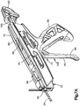
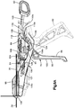
Fig. 1 is a perspective view of a bone fixation assembly constructed in accordance with one embodiment, including a bone fixation instrument and a bone fixation member received by the bone fixation member; -
Fig. 2A is a perspective view of the bone fixation member illustrated inFig. 1 , including a body and a locking member, showing the bone fixation member in an initial configuration; -
Fig. 2B is an enlarged perspective view of a portion of the bone fixation member illustrated inFig. 2A , showing the body inserted through the locking member so as to secure the bone fixation member about an underlying bone; -
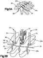
Fig. 3A is a perspective view of a plurality of the bone fixation members illustrated inFig. 2A shown tightened about a target bone and cut; -
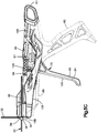
Fig. 3B is a perspective view of the bone fixation instrument illustrated inFig. 1 operatively coupled to and tightening one of a plurality of the bone fixation members illustrated inFig. 3A ; -
Fig. 3C is an enlarged sectional side elevation view of a grip of the bone fixation instrument as illustrated inFig. 3B , shown receiving a free end of the bone fixation member; -
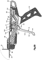
Fig. 3D is a perspective view of the bone fixation instrument illustrated inFig. 1 operatively coupled to and cutting one of the tightened bone fixation members illustrated inFig. 3B ; -
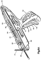
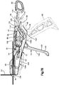
Fig. 4A is a perspective view of the bone fixation instrument illustrated inFig. 1 , with portions removed to illustrate internal components including a tension assembly and a cutter assembly; -
Fig. 4B is a another perspective view of the bone fixation instrument illustrated inFig. 4A ; -
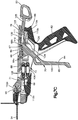
Fig. 5A is a side elevation view of the bone fixation instrument illustrated inFig. 1 , showing the tension assembly in a neutral position; -
Fig. 5B is a sectional side elevation view of the bone fixation instrument as illustrated inFig. 5A ; -
Fig. 5C is another side elevation view of the bone fixation instrument illustrated inFig. 5A , with portions of the instrument removed for the purposes of clarity; -
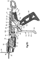
Fig. 6A is a perspective view of the bone fixation instrument illustrated inFig. 1 , showing the tension assembly in a tensioned position; -
Fig. 6B is a side elevation view of the bone fixation instrument as illustrated inFig. 6A ; -
Fig. 6C is a sectional side elevation view of the bone fixation instrument as illustrated inFig. 6A ; -
Fig. 7A is a perspective view of the front end of the bone fixation instrument illustrated inFig. 1 , shown in a cutting mode; -
Fig. 7B is a side elevation view of the bone fixation instrument illustrated inFig. 7A ; -
Fig. 7C is a sectional side elevation view of the bone fixation instrument illustrated inFig. 7A ; -
Fig. 7D is another sectional side elevation view of the bone fixation instrument illustrated inFig. 7A ; -
Fig. 8A is a side elevation view of the bone fixation instrument as illustrated inFig. 7A , but showing the cutting assembly in a cutting configuration; -
Fig. 8B is an enlarged perspective view of an actuator and a locking member of the cutting assembly, showing the actuator in a first configuration; -
Fig. 8C is an enlarged perspective view similar toFig. 8B , but showing the actuator in an armed position, and the locking member configured to lock the actuator in the armed position; -
Fig. 8D is an enlarged perspective view similar toFig. 8C , but showing the actuator and locking member during cutting; and -
Fig. 8E is an enlarged perspective view similar toFig. 8D , but showing the actuator returned to a first position upon completion of cutting. - Certain terminology is used in the following description for convenience only and is not limiting. The words "right", "left", "lower" and "upper" designate directions in the drawings to which reference is made. The words "proximally" and "distally" refer to directions toward and away from, respectively, the surgeon using the surgical instrument. The words, "anterior", "posterior", "superior", "inferior" and related words and/or phrases designate preferred positions and orientations in the human body to which reference is made and are not meant to be limiting. The terminology includes the above-listed words, derivatives thereof and words of similar import.
- Referring to
Figs. 1-3B generally, abone fixation assembly 20 includes abone fixation instrument 22 and at least onebone fixation member 24 such as a plurality ofbone fixation members 24 that are configured to secure a first andsecond bone segments target bone 28, such as a sternum, that are separated at afracture location 30 together in a compressed approximated position. - In accordance with the illustrated embodiment, each
bone fixation member 24 can be substantially configured as a cable tie, and can include aflexible strap 32 defines astrap body 33 and hasfirst end 34a and asecond end 34b opposite thefirst end 34a along the length of thestrap 32, aneedle tip 36 that extends from thefirst end 34a, and alocking mechanism 38 that extends from thesecond end 34b. Thestrap 32 can be made from any suitable biocompatible material as desired, such as PEEK. - Each
bone fixation member 24 can further include afirst initiation region 40 that extends from thefirst end 34a toward thesecond end 34b along a portion of a length of the strap 32 (for instance, approximately 1/3 the length of the strap 32) and asecond locking region 42 that extends between thefirst initiation region 40 and thesecond end 34b. In accordance with the illustrated embodiment, thesecond locking region 42 extends from thefirst initiation region 40 to thesecond end 34b. Thefirst initiation region 40 can include a plurality of small protrusions that extend out from thestrap body 33 and alternate with recessed regions disposed between adjacent protrusions. Alternatively, theinitiation region 40 can be substantially smooth and devoid of protrusions or teeth. Thesecond locking region 42 can include a plurality of lockingteeth 48 that extend out from the strap body 33 a distance greater than the protrusions and are separated by recessedregions 51 disposed between adjacent locking teeth. It should be appreciated that the lockingregion 42 can extend along any portion up to all of thestrap body 33 as desired. The lockingteeth 48 can extend out from one side of thestrap body 33 or both opposed sides of thestrap body 33 as desired. - The
locking mechanism 38 includes a housing 50 astrap receiving slot 52 that extends through thehousing 50 and is configured to receive thefirst end 34a of thestrap 32. In accordance with the illustrated embodiment, thefirst end 34a is inserted through theslot 52 so as to define aloop 55 about thetarget bone 28. Thelocking mechanism 38 is configured to allow thestrap 32 to translate unidirectionally through theslot 52 along the direction of Arrow A so as to reduce the size of theloop 55 about the first andsecond segments target bone 28. For instance, theneedle tip 36 can be inserted through theslot 52 and subsequently removed, for instance by cutting aneck 56 of thestrap body 33 that defines reduced thickness at a location adjacent theneedle tip 36, such that thestrap 32 remains in theslot 52. In accordance with the illustrated embodiment, thelocking mechanism 38 includes a locking member such as atongue 54 that is connected to thehousing 50 and includes at least one complementary tooth such as a plurality of lockingteeth 58 that extend into theslot 52. The lockingteeth 58 define a beveled leadingedge 60 that that is configured to cam over complementary beveled leadingedges 49 of the lockingteeth 48 when thestrap 32 is translated through theslot 52 along the direction of Arrow A. The lockingteeth edges edges 60, such that the trailingedges strap 32 from translating through theslot 52 along the direction opposite Arrow A, which would increase the size of theloop 55. - During operation, the
strap 32 is wrapped around the first andsecond segments target bone 28, and theneedle tip 36 is inserted through theslot 52 and pulled through theslot 52 so as to cause thestrap 32 to subsequently translate through theslot 52. Theneedle tip 36 can be removed from thestrap 32, and thestrap 32 can then be further pulled, for instance manually, through theslot 52. As thestrap 32 is translated through thelocking mechanism 38 along the direction of Arrow A, the small protrusions of theinitiation region 40 can slide through theslot 52 without engaging the lockingteeth 58 of thelocking mechanism 38. As the lockingregion 42 of thestrap 32 is translated through theslot 52 along the direction of Arrow A, the lockingteeth strap 32 from causing thestrap 32 to back out of theslot 52 along a direction opposite Arrow A. For instance, as thestrap 32 translates through thelocking mechanism 38 along the direction of Arrow A, the size of theloop 55 about thetarget bone 28 decreases until tactile feedback indicates that tension has been induced in thestrap 32. - As illustrated in
Fig. 3B , thefixation instrument 22 includes atension assembly 70 that is configured to secure thefixation instrument 22 to thestrap 32, and is further configured to further pull thestrap 32 through thelocking mechanism 38 thereby further inducing tension in thestrap 32 until thestrap 32 has securely compressed the bone first andsecond bone segments target bone 28 together at thefracture location 30. As illustrated inFig. 3C , and as described in more detail below, thetension assembly 70 includes atraveler 98 and agrip 96 configured to be secured to thefree end 35 of thestrap 32. Thegrip 96 is further coupled to thetraveler 98 such that movement of the traveler causes movement of thegrip 96. Thus, when thefixation instrument 22 abuts thehousing 50, and thetraveler 98 moves away from thehousing 50, thegrip 96 likewise moves away from the housing50, thereby inducing tension in thestrap 32. - The
grip 96 can include a firstupper grip member 112a and a secondlower grip member 112b spaced from theupper grip member 112a so as to define agap 116 disposed between the upper andlower grip members upper grip member 112a defines afirst grip surface 114 that faces thelower grip member 112b, and can further define a plurality ofteeth 120a that extend out from thefirst grip surface 114 toward thelower grip member 112b. Theteeth 120a are configured to assist in reliably securing thegrip 96 to thestrap 32. For instance, theteeth 120a can interlock withcomplementary teeth 48 of thestrap 32. Thelower grip member 112b defines asecond grip surface 118 that faces thefirst grip surface 114. Thelower grip member 112b can further define a plurality ofteeth 120b that extend out from thesecond grip surface 118 toward theupper grip member 112a. Theteeth 120b are configured to assist in reliably securing thegrip 96 to thestrap 32. For instance, theteeth 120a can interlock with complementary teeth of thestrap 32. Thus, it should be appreciated that thegrip 96 is configured to engage thefree end 35 of thestrap 32 whether thestrap 32 is oriented such that the teeth of thestrap 32 face up or down. The first and second grip surfaces 114 and 118 can be sized and shaped as desired. In accordance with the illustrated embodiment, the first and second grip surfaces 114 and 118 are curved and substantially arc-shaped in accordance with the illustrated embodiment, such that the first and second grip surfaces 114 and 118 are convex with respect to thegap 116. - The
upper grip member 112a and thelower grip member 112b can be coupled to thetraveler 98 as described above. For instance, theupper grip member 112a can be pivotally coupled to thetraveler 98 at a firstgrip pivot location 113a about a firstgrip pivot pin 115a that defines a first grip pivot axis. Thegrip 96 can further include a biasing member such as a torsion spring that biases theupper grip member 112a to pivot about the firstgrip pivot location 113a so as to bias theteeth 120a toward thegap 116. In particular, thefirst grip surface 114 can extend eccentrically about the firstgrip pivot location 113a such that thegrip surface 114 moves toward thegap 116 under the force of the torsion spring. Similarly, thelower grip member 112b can be pivotally coupled to thetraveler 98 at a secondgrip pivot location 113b about a secondgrip pivot pin 115b that defines a second grip pivot axis. Thegrip 96 can further include a biasing member such as a torsion spring that biases thelower grip member 112b to pivot about the secondgrip pivot location 113b so as to bias theteeth 120b toward thegap 116. In particular, thesecond grip surface 118 can extend eccentrically about the secondgrip pivot location 113b such that thesecond grip surface 118 moves toward thegap 116 under the force of the torsion spring. - Thus, during operation, the
gap 116 receives thefree end 35 of thestrap 32, such that theteeth 48 of thefree end 35 face one or both of the upper andlower grip members free end 35 is received in thegap 116, the upper andlower grip members teeth free end 35. The teeth can be oriented such that theteeth teeth 48 of thefree end 35 as thefree end 35 is inserted into thegap 116 in a rearward direction. Subsequent movement of thetraveler 98 in the rearward direction relative to thehousing 50 of thelocking mechanism 38 causes one or both of theteeth teeth 48 and bias thefree end 35 to move in the rearward direction relative to thehousing 50, thereby inducing tension in thestrap 32. While each of thegrip members grip members free end 35 of thestrap 32 engages thegrip 96 only in a predetermined orientation. - As illustrated in
Fig. 3D , thefixation instrument 22 further includes acutter assembly 72 that is configured to cut afree end 35 of thestrap 32 that has passed through thelocking mechanism 38 once a desired tension has been induced in thestrap 32 about the first andsecond segments target bone 28. For instance, the desired tension can be within a range defined by and between a lower end that can be approximately 50 Newtons or approximately 80 Newtons, and an upper end that can be approximately 150-160 Newtons or 200 Newtons. It should be appreciated that the desired tension can depend on the bone quality and the preference of the surgeon, and can for instance be any tension as desired that reliably secures thetarget bone 28 without overtightening thestrap 32. - Referring now to
Figs. 1 and4A-4B , thefixation instrument 22 includes abody 76 that defines afront end 78a and an opposedrear end 78b spaced from thefront end 78a along a longitudinal direction L and opposedsides 80 that are spaced along a lateral direction A that is substantially perpendicular with respect to the longitudinal direction L. Thefront end 78a is spaced from therear end 78b in a forward direction, and therear end 78b is spaced from thefront end 78a in a rearward direction opposite the forward direction. Thefixation instrument 22 further includes ahandle 82 that is supported by thebody 76, and can extend down from thebody 76 substantially along a transverse T direction that is substantially perpendicular with respect to both the longitudinal direction L and the lateral direction A. In accordance with the illustrated embodiment, the transverse direction T is oriented vertically, and the longitudinal and lateral directions L and A are oriented horizontally, though it should be appreciated that the orientation of the fixation instrument may vary during use. In accordance with the illustrated embodiment, thebody 76 is elongate in the longitudinal direction L. - The
fixation instrument 22 further includes an actuator, such as atrigger 84, that extends down from thebody 76 at a location spaced forward from thehandle 82, and anose 86 disposed at thefront end 78a of thebody 76. Thefixation instrument 22 can further include atoggle member 83 that extends rearward from therear end 78b of thebody 76. As will be described in more detail below, actuation of thetoggle member 83 can cause thefixation instrument 22 to iterate from a tensioning mode to a cutting mode. Thehandle 82, thetrigger 84, and thenose 86 can be discreetly attached to thebody 76 or integral and monolithic with thebody 76 as desired. Thebody 76 can include anouter housing 88 that includes a pair ofhousing members outer sides 92 and can be joined together viafasteners 94 such as dowels or screws or the like or any suitable alternative attachment mechanism so as to support the various internal components of thefixation instrument 22 as described below. - The
housing 80 can support thetension assembly 70 that is configured to inducing tension in thestrap 32 as described above. Thehousing 88 is further configured to support thecutter assembly 72 that is configured to remove thefree end 35 of thestrap 32 once thetension assembly 70 has induced a desired level of tension in thestrap 32. Thetraveler 98 is movable relative to thebody 76. As described above, thetraveler 98 supports thegrip 96, such that movement of thetraveler 98 in the rearward direction relative to thebody 76 likewise causes thegrip 96 to move in the rearward direction relative to thebody 76. Accordingly, when thenose 86 of thebody 76 is braced against thehousing 50 and thegrip 96 is attached to thestrap 32, movement of the traveler in the rearward direction relative to thehousing 50 induces tension in thestrap 32. - The
tension assembly 70 can further include anactuator 100 such as thetrigger 84 and atension limiter 102 connected between thetrigger 84 and thetraveler 98. Thetension assembly 70 can further include a force transfer member 104 (seeFig. 5B ) that is configured to be selectively coupled between thetrigger 84 and thetension limiter 102, thereby operatively coupling thetrigger 84 to thetraveler 98. For instance, thetension limiter 102 can be connected to thetraveler 98 and theforce transfer member 104. Theforce transfer member 104 is thus attached to thetension limiter 102 at a first location, and is configured to be selectively coupled to thetrigger 84 at a second location. The cuttingassembly 72 includes acutter arm 106 that is movably supported by thebody 76 and acutter blade 108 that is carried by the cutter arm 106 (seeFig. 5C ). Thecutter arm 106 is movable from a disengaged configuration (seeFig. 5C ) whereby thecutter blade 108 is spaced from thefree end 35 of thestrap 32 that is received in thegrip 96 to a cutting configuration (seeFig. 8A ) whereby thecutter blade 108 is in a cutting position so as to cut through thefree end 35 of thestrap 32. For instance, thecutter blade 108 can cut through thefree end 35 of thestrap 32 along the transverse direction T. - The
fixation instrument 22 is operable in a tensioning mode whereby thetrigger 84 is coupled to theforce transfer member 104, such that actuation of thetrigger 84 urges theforce transfer member 104 to move rearwardly. Thefixation instrument 22 is further operable in a cutting mode whereby thetrigger 84 is coupled to thecutter arm 106, such that actuation of thetrigger 84 urges the cutter arm to move from the disengaged configuration to the cutting configuration. It should be appreciated that when thefixation instrument 22 is in the tensioning mode, thetrigger 84 is decoupled from thecutter arm 106. Accordingly, actuation of thetrigger 84 does not move thecutter arm 106 to the cutting configuration. Similarly, when thefixation instrument 22 is in the cutting mode, thetrigger 84 is decoupled from theforce transfer member 104, and thus thetraveler 98. Accordingly, actuation of thetrigger 84 does not cause thetraveler 98 to move rearwardly. Thefixation instrument 22 can be placed in the tensioning mode when thetoggle member 83 is in an initial position (seeFigs. 4A-4B ). The fixation instrument can be placed in the cutting mode when thetoggle member 83 is in an armed position (seeFigs. 7A-7D ). it should thus be appreciated that thetrigger 84 is configured to be selectively independently coupled to thetraveler 98 and thecutter arm 106. - During operation, with further reference to
Fig 3C , while thefixation instrument 22 is in the tensioning mode, thefree end 35 of thestrap 32 is received in thegrip 96, thenose 86 is placed against thehousing 50 of thelocking mechanism 38, and theactuator 100 is moved from an first initial position to a second actuated position that causes thetraveler 98 to move rearward, thereby inducing tension in thestrap 32 when the tension in thestrap 32 is less than a select tension, which can be a desired maximum tension as determined by thetension limiter 102. Thefixation instrument 22 can include one ormore rails 93 that are supported by thehousing 88, and extend in the longitudinal direction L through corresponding apertures that extend throughtraveler 98 in the longitudinal direction L. Thus, thetraveler 98 is configured to move along therails 93 in the longitudinal direction L. Thetraveler 98 can further define aslot 69 that extends therethrough in the lateral direction A. Thefixation instrument 22 can further define aguide pin 71 that is fixed to thehousing 88 and extends through theslot 69. Accordingly, theslot 69 moves along theguide pin 71 as thetraveler 98 moves in the longitudinal direction L. Further, the front end of theslot 69 can be defined by a stop surface 73 of thetraveler 98 that is configured to abut theguide pin 71 so as to limit the permitted distance of travel of thetraveler 98 in the rearward direction. When the tension in thestrap 32 reaches the maximum tension as defined by thetension limiter 102, thetension limiter 102 prevents thetraveler 98 from moving rearward when theactuator 100 is moved to the actuated position. Thetraveler 98 can be coupled to aspring arm 99 that bears against thehousing 88 to provide for positional stability of thetraveler 98 during operation. - The
tension limiter 102 includes at least onespring member 128 coupled at its rear end to theforce transfer member 104, and coupled at its front end to thetraveler 98. In one example, thetension limiter 102 can include a pair ofspring members 128 coupled to theforce transfer member 104 and thetraveler 98. Thespring members 128 can be coupled to theforce transfer member 104 and thetraveler 98 in parallel. Alternatively, thespring members 128 can be coupled to theforce transfer member 104 and thetraveler 98 in series. Thespring members 128 can be configured as coil springs or any suitable alternative spring as desired having a spring constant in the longitudinal direction L. As the rear ends of thespring members 128 move in the rearward direction, thespring members 128 bias thetraveler 98 to likewise move in the rearward direction. - Operation of the
tension assembly 70 will now be described with further reference toFigs. 5A-6C , whereby thefixation instrument 22 is in the tensioning mode. As illustrated inFigs. 5A-5C , thetension assembly 70 is in a first initial or neutral configuration, whereby actuation of thetrigger 84 causes a biasing force to be applied to thetraveler 98 in the rearward direction. As illustrated inFigs. 5A-5C , thetrigger 84 is in a first initial or neutral position. As illustrated inFigs. 6A-6C , thetrigger 84 has been actuated from the first initial or neutral position to a second actuated position, which iterates thetension assembly 70 from the first initial or neutral configuration to the actuated configuration, whereby the biasing force is applied to thetraveler 98 in the rearward direction. - Referring to
Figs. 5A-5C in particular, thetrigger 84 can include alower grip portion 85 that extends down from thehousing 88 at a location spaced forward of thehandle 82 and anupper securement portion 89 pivotally connected to thehousing 88. In particular, thetrigger 84 defines aslot 66 that extends through theupper securement portion 89 in the lateral direction A. In particular, theslot 66 can define afront end 66a and arear end 66b that is spaced from thefront end 66a in the rearward direction. Thefixation instrument 22 can further define apivot pin 67 that extends through theslot 66 in the lateral direction A. Thepivot pin 67 defines a trigger pivot axis, such that thetrigger 84 pivots about the trigger pivot axis as defined by thepivot pin 67 in a first pivot direction when actuated from the first position to the second actuated position. The trigger pivot axis can be oriented in the lateral direction A or any suitable alternative direction as desired. As will be appreciated below, thepivot pin 67 is movable along the longitudinal direction L. For instance, when thefixation instrument 22 is in the tensioning mode, thepivot pin 67 is disposed in a first position. When the fixation instrument is in the cutting mode, thepivot pin 67 is disposed in a second position spaced from the first position in the rearward direction. For instance, the first position can be at thefront end 66a of theslot 66. The second position can be at therear end 66b of theslot 66. - The
upper securement portion 89 is further configured to be selectively coupled to and decoupled from theforce transfer member 104. When thetension assembly 70 is in the tensioning mode, theupper securement portion 89 is coupled to theforce transfer member 104. In particular, thetrigger 84 includes anactuation pin 64 that extends out from thesecurement portion 89. For instance, theactuation pin 64 can extend out from thesecurement portion 89 along the lateral direction A. Theforce transfer member 104 can define aslot 68 that extends therethrough along the lateral direction A. For instance, theforce transfer 104 can include a frontinner surface 104a and a rearinner surface 104b that is spaced from the frontinner surface 104a in the rearward direction. The frontinner surfaces 104a and the rearinner surface 104b can cooperate so as to at least partially define theslot 68. Theslot 68 receives theactuation pin 64 when thefixation instrument 22 is in the tensioning mode, such that theactuation pin 64 can bear against the rearinner surface 104b. When thetrigger 84 is in the first position, theactuation pin 64 can be disposed at the mouth of theslot 68. Theslot 68 can be arcuate in shape or can be otherwise shaped as desired. For instance, theslot 64 can be concave with respect to the forward direction. - When the
fixation instrument 22 is in the tensioning mode, thepivot pin 67 is offset from theactuation pin 64 in the forward direction. Further, theactuation pin 64 is offset from thepivot pin 67 in a downward direction. Thus, referring toFigs. 6A-6C , the user can grasp thehandle 82 and thegrip 85 of thetrigger 84 with one hand, and squeeze thetrigger 84, which causes thetrigger 84 to pivot about thepivot pin 67 in a first direction such that thegrip 85 travels rearward toward thehandle 82. Because theactuation pin 64 is spaced rearward with respect to thepivot pin 67, movement of thetrigger 84 about thepivot pin 67 to the actuated position causes theactuation pin 64 to move in the rearward and upward directions. Thus, movement of thetrigger 84 to the actuated position can cause theactuation pin 64 to move further into theslot 68. Further, because theactuation pin 64 bears against the rearinner surface 104b of theforce transfer member 104, movement of the actuation pin in the rearward direction urges theforce transfer member 104 to likewise move in the rearward direction. - It should be appreciated that movement of the
force transfer member 104 in the rearward direction causes the at least onespring member 128 to deform. For instance, the at least onespring member 128 can expand in the longitudinal direction L. Thus, the at least onespring member 128 defines a compressive force that is applied to thetraveler 98 as a biasing force in the rearward direction. It should be appreciated that the at least onespring member 128, and thus thetension limiter 102, has a spring constant that is configured to apply a predetermined biasing force to thetraveler 98 when theforce transfer member 104 has translated rearward a distance corresponding to rearward movement of theactuation pin 64 in response to movement of thetrigger 84 to the actuated position. Accordingly, so long as the tension in theloop 55 is less than a predetermined maximum tension as defined by the spring constant of the at least onespring member 128 and length of travel of theforce transfer member 104, the deformation of thespring member 128 will cause the force applied by thespring member 128 to move thetraveler 98 in the rearward direction. However, once the tension induced in theloop 55 reaches the predetermined maximum tension as defined by thetension limiter 102, deformation of thespring member 128 due to rearward movement of the force transfer member will cause thespring member 128 to apply a rearward biasing force against thetraveler 98 that is insufficient to overcome the force necessary to move thetraveler 98 in the rearward direction and further tighten theloop 55. Thus, at this point, theloop 55 will have reached its maximum predetermined tension as allowed by thefixation instrument 22. - It is recognized that after the
trigger 84 has been moved to the actuated position, and thetraveler 98 has moved in the rearward direction, thereby also causing thefree end 35 to move in the rearward direction relative to thehousing 50 of thelocking mechanism 38, the tension in theloop 55 may or may not have reached the maximum predetermined tension. Whether the tension in theloop 55 is equal to the maximum predetermined tension or less than the maximum predetermined tension can be observed when actuating thetrigger 84 to the actuated position. For instance, if when actuating thetrigger 84 to the actuated position, thefree end 35 of thestrap 32 does not translate in the rearward direction or stops translating in the rearward direction, it can be determined that the tension in theloop 55 has reached the maximum predetermined tension. If, on the other hand, thefree end 35 of thestrap 32 translate in the rearward direction when actuating thetrigger 84 to the actuated position,, it can be determined that the tension in theloop 55 is less than the maximum predetermined tension. - If the tension in the
loop 55 has reached the maximum predetermined tension, then the fixation instrument can be iterated from the tensioning mode to the cutting mode. If, however, the tension in theloop 55 is less than the maximum predetermined tension, then the trigger can again be moved to the actuated position. It should be appreciated that the fixation instrument can include a trigger spring member 146 (seeFig. 5A ) that is connected between the handle 142 and the trigger 144 that biases the trigger 144 to pivot about thepivot pin 67 in a second pivot direction opposite the first pivot direction. Thus, after thetrigger 84 has moved to the actuation position, release of thetrigger 84 allows the force of thetrigger spring member 146 to bias the trigger 144 to pivot about thepivot pin 67 to the first position. Alternatively, thebone fixation instrument 22 can be configured to apply sufficient tension to theloop 55 in one stoke of the trigger 144 such that thebone fixation instrument 22 can be devoid of thetrigger spring member 146. It is appreciated that when thetrigger 84 moves to the first position, theactuation pin 64 moves forward against the frontinner surface 104a of theforce transfer member 104, thereby urging theforce transfer member 104 to move in the forward direction. As theforce transfer member 104 moves in the forward direction, theforce transfer member 104 causes the rear end of the at least onespring member 128 to move in the forward direction. Accordingly, the at least one spring member provides a biasing force that drives thetraveler 98 to move in the forward direction. As thetraveler 98 moves in the forward direction, the at least one of theteeth teeth 48 of thestrap 32 ratchets over theteeth 48. Accordingly, thetraveler 98 moves along thefree end 35 of thestrap 32 in the forward direction. Tthe engagement of the lockingteeth loop 55 from allowing thefree end 35 to move through the housing in a direction opposite Arrow A that would reduce the tension in the loop 55 (seeFig. 2B ). - Accordingly, once a trigger stroke has been completed whereby the
trigger 84 has been moved to its actuated position as illustrated inFig. 6A , the user can release thetrigger 84 which causes thetrigger spring member 146 to bias thetrigger 84 to its forward position shown inFig. 5A . Once thetrigger 84 has moved to its forward position, thetrigger 84 and thus thetension assembly 70 is in the first initial configuration. Thetrigger 84 can again be moved to the actuated position, thereby causing thetraveler 98 to move in the rearward direction as described above. The trigger can be released and actuated as many times as desired until the tension in theloop 55 has reached the predetermined maximum tension as defined by thetension limiter 102. - It should appreciated that the
tension limiter 102 can be configured to apply a rearward biasing force against thetraveler 98 that is greater than the tension induced in theloop 55 about thetarget bone 28. For instance, the at least onespring member 128 can apply a force to thetraveler 98 in the rearward direction that is sufficient to overcome both the tension of theloop 55 and the additional force that causes one or both of the lockingteeth Fig. 2B ). Accordingly, thetension limiter 102 can be configured apply a force that is greater than, but corresponds to, the tension in theloop 55 about the target bone. Thus, the maximum force applied by thetension limiter 102 can correspond to the maximum desired tension in theloop 55, it being appreciated that once theteeth loop 55 can decrease somewhat as theteeth tension limiter 102 can apply a maximum force as desired, for instance up to approximately 430 Newtons or any other force as desired that corresponds to a desired maximum tension in theloop 55 about thetarget bone 28. As a result, once the desired maximum tension in theloop 55 has been induced about thetarget bone 28, the force applied by thetension limiter 102 when thetrigger 84 is fully actuated is insufficient to cause theteeth loop 55. Accordingly, once the maximum tension in theloop 55 has been induced about thetarget bone 28, the force applied by thetension limiter 102 to the traveler will be insufficient to cause thetraveler 98 to translate rearward a sufficient distance that further tightens theloop 55 about thetarget bone 28. Once the tension in theloop 55 has reached the maximum predetermined tension, thetrigger 84 can be released, and theactuation pin 64 can return to the mouth of theslot 68 as illustrated inFig. 5B . - Referring now to
Figs. 7A-7D , and as described above, thefixation instrument 22 includes thecutter assembly 72 that is configured to sever thefree end 35 of thestrap 32 after the tension in theloop 55 has reached the maximum predetermined tension. For instance, thetoggle member 83 can be moved in the rearward direction away from thebody 76 to iterate thefixation device 22 from the tensioning mode to the cutting mode. In particular, the fixation device includes asupport arm 105 that is attached to thetoggle member 83 at a first end, and supports thepivot pin 67 at a second end that is spaced forward from the first end. It should be appreciated that thesupport arm 105 can be monolithic with thetoggle member 83 as desired. Thesupport arm 105 and thetoggle member 83 can define an actuator assembly configured to move in the rearward direction from a first position to a second position. Thesupport arm 105 is supported by thehousing 88, and is configured to move between a first forward position and a second rearward position. In one example, thesupport arm 105 is configured to move along the longitudinal direction L. When thetoggle member 83 is at a first position, thesupport arm 105 is at the first position whereby thepivot pin 67 is at the first position in theslot 66 as described above with respect toFigs. 5A-5C . When thetoggle member 83 moves to the second armed position, thesupport arm 105 moves along with thetoggle member 83 to the respective second position whereby thepivot pin 67 is in the second position is at the second position in theslot 66. - In one example, the
toggle member 83 is pulled away from thehousing 88 in the rearward direction as it moves from the first position to the second position. Thefixation instrument 22 can include anactuator spring member 109 coupled between thesupport arm 105 and thehousing 88. For instance, theactuator spring member 109 can be attached at a first end to thesupport arm 105, and attached at a second end to one of thefixation members 94 that extends between opposed sides of thehousing 88. The second end can be spaced from the first end in the forward direction, but it should be appreciated that theactuator spring member 109 can be configured such that the second end is spaced from the first end in the rearward direction. As thesupport arm 105 travels in the rearward direction from the first position to the second position, the first end of theactuator spring member 109 moves away from the second end of theactuator spring member 109, thereby expanding the actuator spring member. Accordingly, theactuator spring member 109 applies a spring force to thesupport arm 105 that biases thesupport arm 105 in the forward direction. Accordingly, movement of thetoggle member 83 in the rearward direction is against the spring force of theactuator spring member 109. - Referring also to
Figs. 8B-8C , thefixation instrument 22 includes a lockingmember 110 that is configured to releasably lock thetoggle member 83 in the second position. The lockingmember 110 can include a lockingportion 110a and at least onespring portion 110b that projects out from the lockingportion 110a and bears against thehousing 88. For instance, the lockingmember 110 can include a pair ofspring portions 110b spaced from each other in the lateral direction A. The lockingmember 110 is pivotally supported by apivot pin 130 that is supported by thehousing 88. Thespring portion 110b can be compressed so as to bias the lockingportion 110a against thesupport arm 105. When thetoggle member 83 is moved to the second position, the lockingportion 110a is configured to engage thesupport arm 105 so as to prevent thesupport arm 105 from returning to the first position under the force of theactuator spring member 109. For instance, the lockingportion 110a can include aprojection 111, and thesupport arm 105 can define anaperture 123 sized to receive the projection. When thesupport arm 105 and thetoggle member 83 are in the first position, theaperture 123 is spaced from theprojection 111 in the forward direction, but is aligned with theprojection 111 along the longitudinal direction. Accordingly, when thetoggle member 83 is moved to the second position, thespring portion 110b causes the lockingmember 110 to pivot about thepivot pin 130 such that the lockingportion 110a is inserted into theaperture 123 under the force of thespring portion 110b. For instance, theprojection 111 can be inserted into theaperture 123. As a result, the force of theactuator spring member 109 causes thesupport arm 105 to bear against the lockingportion 110a, thereby preventing the actuator from returning from the second position to the first position. - As illustrated in
Fig. 5A , when thetrigger 84 is in the first position, thefront end 66a of theslot 66 can be disposed above therear end 66b of theslot 66. Accordingly, referring again toFigs. 7A-7D , when thepivot pin 67 moves from thefirst end 66a to thesecond end 66b in the rearward direction as theactuation arm 105 moves from the first position to the second position, thepivot pin 67 can bias thetrigger 84 to pivot about thepivot pin 67 in a second direction opposite the first direction. Accordingly, theactuation pin 64 can move out of theslot 68 such that theactuation pin 64 is disposed adjacent thecutter arm 106. For instance, theactuation pin 64 can move down and out of theslot 68. In one example, theactuation pin 64 can abut thecutter arm 106. Because theactuation pin 64 is disposed out of the slot and out of alignment with theforce transfer member 104, movement of thetrigger 84 in the first direction from the first position toward the second position does not cause theactuation pin 64 to bear against theforce transfer member 104 in the rearward direction. As a result, thetrigger 84 is decoupled from theforce transfer member 104 when thefixation instrument 22 is in the cutting mode. It should be appreciated that if thebone fixation instrument 22 is devoid of thetrigger spring member 146, movement of thepivot pin 67 to the second position can cause thetrigger 84 to move about thepivot pin 67 toward the first position whereby theactuation pin 64 moves down out of theslot 68 as described above. - Further, when the
pivot pin 67 is disposed at the second position in theslot 66, thepivot pin 67 is offset with respect to theactuation pin 64 in the rearward direction. Thus, the actuator is configured to move about a first pivot axis when the bone fixation instrument is in the tensioning mode, and the actuator moves about a second pivot axis spaced from the first pivot axis in the rearward direction when the bone fixation instrument is in the cutting mode. Accordingly, as illustrated inFig. 8A , when thetrigger 84 is actuated to pivot about thepivot pin 67 in the first direction such that thegrip portion 84 moves toward thehandle 82, theactuation pin 64 moves down along the transverse direction against thecutter arm 106. Thecutter arm 106 includes afront portion 106a and arear portion 106b spaced from thefront portion 106a in the rearward direction. Thecutter arm 106 is supported at acutter pivot pin 121. - The
cutter pivot pin 121 is supported by the housing such that thecutter arm 106 is configured to pivot about thecutter pivot pin 121. Thefront portion 106a extends forward from thecutter pivot pin 121, and therear portion 106b extends rearward from thecutter pivot pin 121. Thus, thecutter pivot pin 121 is disposed between thefront portion 106a and therear portion 106b. Theactuation pin 64 abuts therear portion 106b of thecutter arm 106. The cutter blade 108a extends from thefront portion 106a. For instance, the cutter blade 108a can extend up from thefront portion 106a of thecutter arm 106. Accordingly, when thetrigger 84 is biased to pivot in the first direction from the first position toward the second position, theactuation pin 64 biases thecutter arm 106 to pivot about thecutter pivot pin 121 in a first cutter direction from a first position to a cut position whereby thecutter blade 108 is brought into contact with thefree end 35 of thestrap 32, thereby severing thefree end 35. For instance, thecutter blade 108 can sever thefree end 35 at a location such that thehousing 50 is disposed between theloop 55 and thecutting blade 108. In accordance with one embodiment, thecutter blade 108 can be spaced from thenose 86 in the rearward direction. Accordingly, thenose 86 can be disposed between thecutter blade 108 and thehousing 50. - The
cutter arm 106 can include abiasing arm 124 and a spring member126 that each extends out from therear portion 106b. Thespring member 126 can be in the form of a spring arm that bears against thehousing 88 so as to bias thecutter arm 106 to pivot in a second cutter direction opposite the first cutter direction about thecutter pivot pin 121. Thus, after thecutter blade 108 has severed thefree end 35 and thetrigger 84 is released, thespring member 126 biases thecutter pivot pin 121 to pivot in the second cutter direction. Pivoting of thecutter pivot pin 121 in the second cutter direction causes thebiasing arm 124 to bear against a bearingsurface 132 of the lockingmember 110. Thepivot pin 130 can be disposed rearward of the bearingsurface 132, and forward of both the lockingportion 110a and thespring portion 110b. As the biasingarm 124 bears against the biasingsurface 132, the lockingmember 110, the locking member is driven to pivot about thepivot pin 130 until the lockingportion 110a is removed from theaperture 123. Accordingly, the force of theactuator spring member 109 biases thesupport arm 105 and thetoggle member 83 to move forward as illustrated inFig. 8D until thepivot pin 67 is disposed in theslot 66 as described above with respect toFigs. 5A-5C . Thus, thefixation instrument 22 is iterated from the cutting mode to the tensioning mode as described above. It should therefore be appreciated that thefixation instrument 22 does not allow a subsequent actuation of thetrigger 84 to move the cutter arm to the cut position without first moving thetoggle member 83 to the second position as described above with respect toFigs. 7A-7D . When thefixation instrument 22 has returned to the tensioning mode, thegrip 96 is configured to receive thefree end 35 of anotherstrap 32 so as to tension therespective loop 55 and subsequently sever thefree end 35 in the manner described above. - Although the disclosure has been described in detail, it should be understood that various changes, substitutions, and alterations can be made herein without departing from the scope of the invention as defined by the appended claims. Moreover, the scope of the present disclosure is not intended to be limited to the particular embodiments described in the specification. As one of ordinary skill in the art will readily appreciate from the disclosure of the present invention, processes, machines, manufacture, composition of matter, means, methods, or steps, presently existing or later to be developed that perform substantially the same function or achieve substantially the same result as the corresponding embodiments described herein may be utilized according to the present disclosure.
Claims (15)
- A bone fixation instrument (22) having a front end (78a) and a rear end (78b) spaced from the front end (78a) in a rearward direction, the bone fixation instrument (22) configured to apply tension to a bone fixation member (24) so as to tighten the bone fixation member (24) about a target bone (26a, 26b), the bone fixation instrument (22) comprising:a grip (96) configured to attach to a free end (35) of the bone fixation member (24);a traveler (98) that supports the grip (96) such that as the traveler (98) moves in the rearward direction, the grip (96) moves along with the traveler (98) in the rearward direction so as to increase tension in the bone fixation member (24) when the grip (96) is attached to the bone fixation member (24); anda cutter arm (106) that carries a cutter blade (108), the cutter arm (106) configured to move the cutter blade (108) to a cutting position whereby the cutter blade (108) severs the free end (35) of the bone fixation member (24) when the grip (96) is attached to the bone fixation member (24);characterized byan actuator (84) configured to selectively pivot about a first pivot axis and a second pivot axis that is spaced from the first pivot axis, such that when the actuator (84) pivots about the first pivot axis, the actuator (84) causes a force to be applied to the traveler (98) in the rearward direction, and when the actuator (84) pivots about the second pivot axis, the actuator (84) causes a force to be applied to the cutter arm (106), thereby causing the cutter arm (106) to move the cutting blade (108) to the cutting position, wherein the actuator (84) defines a slot (66) and the fixation instrument (22) further defines a pivot pin (67) that extends through the slot (66), wherein the pivot pin (67) is movable along the slot (66) between a first position in the slot (66) so as to define the first pivot axis and a second position spaced from the first position so as to define the second pivot axis.
- The bone fixation instrument as recited in claim 1, wherein the actuator (84) is configured to be selectively independently coupled to the traveler (98) and the cutter arm (106).
- The bone fixation instrument as recited in claim 1 or 2, wherein the actuator (84) is coupled to the traveler (98) when the actuator (84) pivots about the first pivot axis, and the actuator (84) is coupled to the cutter arm (106) when the actuator (84) pivots about the second pivot axis, and/or wherein the actuator (84) is decoupled from the cutter arm (106) when the actuator (84) pivots about the first pivot axis, and the actuator (84) is decoupled from the traveler (98) when the actuator (84) pivots about the second pivot axis.
- The bone fixation instrument as recited in any one of claims claim 1 to 3, further comprising a toggle member (83) movable between a first and a second position, wherein 1) when the toggle member (83) is in the first position, the bone fixation instrument (22) is in a tensioning mode whereby movement of the actuator (84) about the first pivot axis causes the traveler (98) to move in the rearward direction until the tension in the bone fixation member (24) reaches a predetermined tension when the grip (96) is attached to the bone fixation member (24), and 2) when the toggle member (83) is in the second position, the bone fixation instrument (22) is in a cutting mode whereby movement of the actuator (84) about the second pivot axis causes the cutter arm (106) to move the cutter blade (108) to the cutting position.
- The bone fixation instrument as recited in claim 4, wherein the pivot pin (67) is in the first position when the bone fixation instrument (22) is in the tensioning mode, and the pivot pin (67) is in the second position spaced from the first position in the rearward direction when the bone fixation instrument (22) is in the cutting mode.
- The bone fixation instrument as recited in claim 4 or 5, further comprising a force transfer member (104) and a tension limiter (102) coupled between the force transfer member (104) and the traveler (98), wherein the force transfer member (104) is coupled to the actuator (84) when the bone fixation instrument (22) is in the tensioning mode, and decoupled from the actuator (84) when the bone fixation instrument (22) is in the cutting mode.
- The bone fixation instrument as recited in claim 6, wherein deformation of the tension limiter (102) causes the traveler (98) to move rearward in response to movement of the actuator (84) toward the second position when the tension in the bone fixation member (24) is less than a predetermined tension, and does not cause the traveler (98) to move in the rearward direction in response to movement of the actuator (84) toward the second position when the tension in the bone fixation member (24) reaches the predetermined tension.
- The bone fixation instrument as recited in claim 6 or 7, wherein the tension limiter (102) further causes the traveler (98) to move in a forward direction opposite the rearward direction when the actuator (84) moves from the second position toward the first position while the bone fixation instrument (22) is in the tensioning mode.
- The bone fixation instrument as recited in any one of claims 6 to 8, wherein the tension limiter (102) comprises a spring member (128) connected between the actuator (84) and the traveler (98), wherein movement of the actuator (84) causes the spring member (128) to flex and bias the traveler (98) rearward under a biasing force when the bone fixation instrument (22) is in the tensioning mode, wherein the traveler (98) preferably moves rearward when the biasing force is greater than the tension in the bone fixation member (24), wherein the traveler (98) further preferably remains stationary when the biasing force is not greater than the tension in the bone fixation member (24).
- The bone fixation instrument as recited in claim 9, wherein the grip (96) interlocks with the free end (35) of the bone fixation member (24) while the grip (96) moves in the rearward direction, and the grip (96) rides along the free end (35) of the bone fixation member (24) when the grip (96) moves in the forward direction.
- The bone fixation instrument as recited in any one of claims 7 to 10, wherein the actuator (84) defines an actuation pin (64) that is received in a slot (68) of the force transfer member (104) when the bone fixation instrument (22) is in the tensioning mode, and is removed from the slot (68) when the bone fixation instrument (22) is in the cutting mode, wherein preferably the actuation pin (64) abuts the cutting arm (106) when the bone fixation instrument (22) is in the cutting mode, wherein further preferably movement of the actuator (84) causes the actuation pin (64) to drive the cutting arm (106) to move the cutting blade (108) to the cutting position.
- The bone fixation instrument as recited in any one of claims 4 to 11, wherein movement of the toggle member (83) to the second position causes the actuator (84) to abut the cutter arm (106) when the bone fixation instrument (22) is in the cutting mode.
- The bone fixation instrument as recited in any one of claims 4 to 12, wherein the grip (96) further comprises first and second grip members (112a, 112b) each having teeth (120a, 120b) configured to interlock with complementary teeth (48) of the bone fixation member (24).
- The bone fixation instrument as recited in any one of claims 4 to 13, further comprising a locking member (54) that is configured to releasably lock the toggle member (83) in the second position against a spring force that biases the toggle member (83) from the second position toward the first position, wherein preferably the cutting arm (106) is configured to abut the locking member (54) so as to remove the locking member (54) from the toggle member (83) after the cutting blade (108) has severed the free end (35) of the bone fixation member (24).
- A bone fixation assembly (20) comprising the bone fixation instrument (22) as recited in any one of claims 1 to 14, and the bone fixation member (24).
Applications Claiming Priority (2)
| Application Number | Priority Date | Filing Date | Title |
|---|---|---|---|
| US201462005552P | 2014-05-30 | 2014-05-30 | |
| PCT/US2015/029214 WO2015183485A1 (en) | 2014-05-30 | 2015-05-05 | Bone fixation assembly |
Publications (2)
| Publication Number | Publication Date |
|---|---|
| EP3148462A1 EP3148462A1 (en) | 2017-04-05 |
| EP3148462B1 true EP3148462B1 (en) | 2018-04-18 |
Family
ID=53181353
Family Applications (1)
| Application Number | Title | Priority Date | Filing Date |
|---|---|---|---|
| EP15723087.1A Not-in-force EP3148462B1 (en) | 2014-05-30 | 2015-05-05 | Bone fixation assembly |
Country Status (7)
| Country | Link |
|---|---|
| US (1) | US9603646B2 (en) |
| EP (1) | EP3148462B1 (en) |
| JP (1) | JP6571174B2 (en) |
| CN (1) | CN106470628B (en) |
| AU (1) | AU2015267531B2 (en) |
| CA (1) | CA2950706A1 (en) |
| WO (1) | WO2015183485A1 (en) |
Cited By (1)
| Publication number | Priority date | Publication date | Assignee | Title |
|---|---|---|---|---|
| US11730527B2 (en) | 2019-11-04 | 2023-08-22 | Stryker European Operations Limited | Surgical instrument for tightening a bone fixation member around bone |
Families Citing this family (22)
| Publication number | Priority date | Publication date | Assignee | Title |
|---|---|---|---|---|
| US9084644B2 (en) | 2011-02-02 | 2015-07-21 | DePuy Synthes Products, Inc. | Bone fixation assembly |
| US8740949B2 (en) | 2011-02-24 | 2014-06-03 | Spinal Elements, Inc. | Methods and apparatus for stabilizing bone |
| USD739935S1 (en) | 2011-10-26 | 2015-09-29 | Spinal Elements, Inc. | Interbody bone implant |
| WO2014014815A1 (en) * | 2012-07-14 | 2014-01-23 | Charles Lang | Bone fixation device and method |
| US10010359B2 (en) | 2013-03-15 | 2018-07-03 | Zimmer Biomet CMF and Thoracic, LLC | Sternal closure cerclage, plate implant and instrumentation |
| US9820755B2 (en) | 2013-03-15 | 2017-11-21 | Zimmer Biomet CMF and Thoracic, LLC | Sternal closure cerclage, plate implant and instrumentation |
| US9839450B2 (en) | 2013-09-27 | 2017-12-12 | Spinal Elements, Inc. | Device and method for reinforcement of a facet |
| US9456855B2 (en) | 2013-09-27 | 2016-10-04 | Spinal Elements, Inc. | Method of placing an implant between bone portions |
| US9820793B1 (en) * | 2014-04-21 | 2017-11-21 | Dallen Medical, Inc. | Tensioning devices and methods for dynamic suture systems |
| US10052143B2 (en) * | 2014-04-30 | 2018-08-21 | DePuy Synthes Products, Inc. | Tensioning instrument and related bone fixation systems and methods |
| US9603646B2 (en) * | 2014-05-30 | 2017-03-28 | DePuy Synthes Products, Inc. | Bone fixation assembly |
| WO2016044432A1 (en) | 2014-09-17 | 2016-03-24 | Spinal Elements, Inc. | Flexible fastening band connector |
| FR3026636B1 (en) * | 2014-10-01 | 2017-09-15 | Cousin Biotech | ANCHORAGE FOR TENSIONING A LONGILINE ELEMENT FOR ATTACHING AN IMPLANT TO A BONE MEMBER |
| CN107854169B (en) * | 2017-11-10 | 2024-03-08 | 中国人民解放军总医院 | Locking device for bone fixation needle |
| US11020149B2 (en) * | 2018-02-28 | 2021-06-01 | Globus Medical Inc. | Scoliosis correction systems, methods, and instruments |
| US11395687B2 (en) * | 2019-03-01 | 2022-07-26 | DePuy Synthes Products, Inc. | Insertion tool for flip anchor cable system insertion |
| US11457959B2 (en) * | 2019-05-22 | 2022-10-04 | Spinal Elements, Inc. | Bone tie and bone tie inserter |
| US11464552B2 (en) * | 2019-05-22 | 2022-10-11 | Spinal Elements, Inc. | Bone tie and bone tie inserter |
| US11819255B2 (en) * | 2019-10-07 | 2023-11-21 | Ortho Development Corporation | Tether tensioning instrumentation and related methods |
| US11304733B2 (en) * | 2020-02-14 | 2022-04-19 | Spinal Elements, Inc. | Bone tie methods |
| CN111772760B (en) * | 2020-08-18 | 2021-07-27 | 西安康拓医疗技术股份有限公司 | Binding gun for sternal suture |
| US11534222B2 (en) | 2020-10-07 | 2022-12-27 | Globus Medical, Inc. | Tensioning instruments |
Family Cites Families (115)
| Publication number | Priority date | Publication date | Assignee | Title |
|---|---|---|---|---|
| US1641077A (en) * | 1924-11-21 | 1927-08-30 | Fouquet Eugene | Binding and cutting pliers |
| US3111945A (en) * | 1961-01-05 | 1963-11-26 | Solbrig Charles R Von | Bone band and process of applying the same |
| US3169560A (en) | 1962-03-08 | 1965-02-16 | Panduit Corp | Binder strap tool |
| US3570497A (en) | 1969-01-16 | 1971-03-16 | Gerald M Lemole | Suture apparatus and methods |
| US3577601A (en) | 1969-03-12 | 1971-05-04 | Thomas & Betts Corp | Article fastening device |
| US3661187A (en) * | 1969-07-28 | 1972-05-09 | Panduit Corp | Strap-tensioning and severing tool |
| US3645302A (en) * | 1970-03-19 | 1972-02-29 | Panduit | Strap installation tool |
| US3830263A (en) * | 1973-06-07 | 1974-08-20 | Amp Inc | Strap applying tool |
| US4093005A (en) * | 1977-02-28 | 1978-06-06 | All States Plastic Manufacturing Co. Inc. | Cable tie gun |
| EP0009327A1 (en) | 1978-09-01 | 1980-04-02 | Herbert D. Huddleston | Hip nail and method for its use |
| DE3244680C2 (en) | 1982-12-02 | 1984-10-18 | Peter Dr. 8445 Schwarzach Clarenz | Device for holding the parts of a broken bone together |
| US4535764A (en) | 1983-04-15 | 1985-08-20 | Tayco Developments, Inc. | Surgical bone tie |
| US4955913A (en) | 1985-03-28 | 1990-09-11 | Robinson Walter C | Surgical tie |
| DE3517204A1 (en) | 1985-05-13 | 1986-11-13 | Gerald Dr. 8000 München Hauer | PERMANENTLY PLASTIC TAPE WITH SELF-HOLDER |
| DE3538645A1 (en) | 1985-10-30 | 1987-05-07 | Gundolf Ferdinand | Device for the osteosynthesis of bone fragments, especially for the fixation of bone fractures |
| US4730615A (en) | 1986-03-03 | 1988-03-15 | Pfizer Hospital Products Group, Inc. | Sternum closure device |
| AU1684788A (en) | 1987-02-20 | 1988-09-14 | Edward M. Farrell | Surgical tying devices |
| US4813416A (en) * | 1987-03-18 | 1989-03-21 | The Research Foundation Of State University Of New York | Bonding assembly and method for sternum closing |
| DE8709487U1 (en) | 1987-07-09 | 1987-10-15 | Paul Hellermann Gmbh, 2080 Pinneberg, De | |
| US4966600A (en) * | 1989-01-26 | 1990-10-30 | Songer Robert J | Surgical securance method |
| DE4021246A1 (en) | 1990-07-04 | 1992-01-09 | Gundolf Ferdinand | Holding fractured bone in place - involves use of pipe clip with tensioning screw |
| DE4024334A1 (en) | 1990-07-31 | 1992-02-06 | Gundolf Ferdinand | Strap for setting bone fracture - has clamping lever with claw which engages slot in strap end away from bone |
| DE4200757A1 (en) | 1991-01-14 | 1992-07-16 | Gundolf Ferdinand | Osteosynthesis instrument - has mounting at end of clamping strip through which other end is passed before bending backwards |
| US5146645A (en) | 1991-03-01 | 1992-09-15 | The Procter & Gamble Company | Toothbrush employing resiliently buckling arch to indicate excessive brushing pressure |
| US5146654A (en) | 1991-05-03 | 1992-09-15 | Panduit Corp. | Stretched cable tie |
| GB9111972D0 (en) | 1991-06-04 | 1991-07-24 | Clinical Product Dev Ltd | Medical/surgical devices |
| KR930004380Y1 (en) | 1991-06-14 | 1993-07-14 | 조우신 | Bone joining metal plate |
| DE4127550A1 (en) | 1991-08-20 | 1993-02-25 | Telos Herstellung Und Vertrieb | Implantable surgical connecting plate - is used for attaching strap to bone and has two parallel slots to hold strap to plate |
| US5361475A (en) | 1992-02-05 | 1994-11-08 | Daniels Manufacturing Corporation | Safety cable tool |
| GB9206018D0 (en) | 1992-03-19 | 1992-04-29 | Dall Desmond Meiring | Bone fixation system |
| US5193250A (en) | 1992-04-30 | 1993-03-16 | Panduit Corp. | Releasable cable tie |
| DE4224826C2 (en) * | 1992-07-27 | 1995-09-07 | United Carr Gmbh Trw | Device for tensioning at least one profiled band element wrapped around at least one tubular body |
| DE4228909C2 (en) | 1992-08-28 | 1994-06-09 | Ethicon Gmbh | Endoscopic instrument for the application of ligature binders and ligature binders |
| US5356417A (en) | 1992-10-09 | 1994-10-18 | United States Surgical Corporation | Absorbable sternum closure buckle |
| US5355913A (en) * | 1992-10-09 | 1994-10-18 | United States Surgical Corporation | Surgical repair device |
| US5403346A (en) | 1992-12-31 | 1995-04-04 | Loeser; Edward A. | Self-affixing suture assembly |
| US5496318A (en) | 1993-01-08 | 1996-03-05 | Advanced Spine Fixation Systems, Inc. | Interspinous segmental spine fixation device |
| US5366461A (en) | 1993-01-25 | 1994-11-22 | William Blasnik | Sternum banding assembly |
| CA2088119C (en) | 1993-01-26 | 1998-09-01 | William Blasnik | Sternum banding assembly |
| FR2702951B1 (en) | 1993-03-26 | 1995-06-16 | Cremascoli France | BONE STRAPPING DEVICE. |
| US5540698A (en) * | 1993-04-21 | 1996-07-30 | Amei Technologies Inc. | System and method for securing a medical cable |
| EP0737445A3 (en) | 1993-07-06 | 1996-11-06 | Ferdinand Gundolf | Pliers for placing and driving a spike in a bone |
| EP0647436A1 (en) | 1993-10-06 | 1995-04-12 | SMITH & NEPHEW RICHARDS, INC. | Bone section reattachment apparatus |
| US5462542A (en) | 1994-01-24 | 1995-10-31 | United States Surgical Corporation | Sternum buckle with serrated strap |
| WO1995022294A1 (en) | 1994-02-17 | 1995-08-24 | Surgical Accessories, Inc. | Fastener and tensioner for bone securing cable |
| US5607430A (en) | 1995-08-25 | 1997-03-04 | Biomet, Inc. | Bone stabilization implant having a bone plate portion with integral cable clamping means |
| US5636412A (en) | 1995-11-01 | 1997-06-10 | The Procter & Gamble Company | Fixed circumference binding device with non-protruding free end and method for binding therewith |
| FR2742649B1 (en) | 1995-12-22 | 1998-04-10 | Robert Louis Boutet | STRAPPING LINK FOR MEDICAL USE AND METHOD OF LAYING THE SAME |
| US5741259A (en) | 1996-02-22 | 1998-04-21 | Chan; Kwan-Ho | Surgical fastener device for use in bone fracture fixation |
| US5683404A (en) | 1996-06-05 | 1997-11-04 | Metagen, Llc | Clamp and method for its use |
| ES2243854T3 (en) * | 1996-08-28 | 2005-12-01 | THOMAS & BETTS CORPORATION | USEFUL TO INSTALL ELEMENTS OF CABLE HOLDING. |
| US5972006A (en) | 1997-01-28 | 1999-10-26 | Stony Brook Surgical Innovations, Inc. | Buckle securing means for sternum banding assembly |
| US5810824A (en) | 1997-02-13 | 1998-09-22 | Chan; Kwan-Ho | Surgical fastener assembly and method for bone fracture fixation |
| DE19716504A1 (en) | 1997-04-19 | 1998-12-03 | Hinze Manfred Dr Med Habil | Compression hoop for applying metal band around bone |
| EP0876798A3 (en) | 1997-05-05 | 2000-01-19 | Rainer Otto | Strapping apparatus for fixing bone fractures |
| DE19806628C2 (en) | 1998-02-18 | 2000-08-10 | Daimler Chrysler Aerospace | Cable ties for bundling or fastening cables |
| US6099527A (en) | 1998-04-30 | 2000-08-08 | Spinal Concepts, Inc. | Bone protector and method |
| US6482208B1 (en) * | 1998-11-25 | 2002-11-19 | Alliance Orthopedic, Inc. | Fracture reduction clamp |
| US6050998A (en) | 1999-05-21 | 2000-04-18 | Stephen A. Fletcher | Bone fastener |
| DE29916884U1 (en) | 1999-09-24 | 2000-11-02 | Link Waldemar Gmbh Co | Surgical cerclage tape |
| US6514255B1 (en) | 2000-02-25 | 2003-02-04 | Bret Ferree | Sublaminar spinal fixation apparatus |
| US7993349B2 (en) * | 2000-07-27 | 2011-08-09 | Synthes Usa, Llc | Cranial flap clamp instrument |
| US6589246B1 (en) | 2001-04-26 | 2003-07-08 | Poly-4 Medical, Inc. | Method of applying an active compressive force continuously across a fracture |
| US6489246B1 (en) | 2001-05-01 | 2002-12-03 | Eastman Kodak Company | Method for manufacturing charge-coupled image sensors |
| US6520965B2 (en) | 2001-05-23 | 2003-02-18 | Alan Chervitz | Apparatus and method for orthopedic fixation |
| US6752810B1 (en) * | 2002-05-31 | 2004-06-22 | Pilling Weck Incorporated | Instrument and method for pulling and twisting a tie onto two separated items |
| US20030236538A1 (en) | 2002-06-19 | 2003-12-25 | Thomas Aikens | Artery and vein coupling tie string |
| FR2842724B1 (en) | 2002-07-23 | 2005-05-27 | Spine Next Sa | VERTEBRAL FASTENING SYSTEM |
| US7164360B2 (en) | 2002-08-14 | 2007-01-16 | Mark Schiebler | Multi-use linkage device |
| GB0219280D0 (en) | 2002-08-19 | 2002-09-25 | Finsbury Dev Ltd | Prosthesis |
| JP2004113392A (en) | 2002-09-25 | 2004-04-15 | Koseki Ika Kk | Band for suturing sternum |
| JP2004113520A (en) | 2002-09-26 | 2004-04-15 | Koseki Ika Kk | Suture material for surgery with insert-molded needle |
| US7582088B2 (en) * | 2003-02-07 | 2009-09-01 | Dsm Ip Assets B.V. | Bone fixing device |
| JP4098137B2 (en) | 2003-03-31 | 2008-06-11 | 小池 央 | Method of organ removal from mammals other than humans, and method of ovariectomy |
| GB0308647D0 (en) | 2003-04-15 | 2003-05-21 | Qualiteam S A S | Suture band |
| US7648504B2 (en) | 2003-09-09 | 2010-01-19 | Bioretec Ltd | Bioabsorbable band system |
| WO2005074827A1 (en) * | 2004-01-30 | 2005-08-18 | Dsm Ip Assets B.V. | Fixing device for clamping the ends of a surgical cable used for fixing bone parts |
| EP1564144B1 (en) | 2004-02-13 | 2009-06-24 | Thomas & Betts International, Inc. (a Corporation of the state of Delaware) | Tension and anti-recoil mechanism for cable tie tool |
| GB2414936A (en) | 2004-06-09 | 2005-12-14 | Ravi Kumar Khetrapal | Fracture reduction apparatus |
| US7008429B2 (en) | 2004-06-23 | 2006-03-07 | Golobek Donald D | Bio-absorbable bone tie with convex head |
| US7229444B2 (en) | 2004-08-25 | 2007-06-12 | Howmedica Osteonics Corp. | Trochanteric cerclage plate |
| DE202004015582U1 (en) | 2004-10-07 | 2004-12-23 | Merete Medical Gmbh | Cerclage pen for the fixation of stabilizing plates |
| WO2006062419A1 (en) | 2004-12-08 | 2006-06-15 | Enztec Limited | Securing means for surgical use |
| US20060142772A1 (en) | 2004-12-29 | 2006-06-29 | Ralph James D | Surgical fasteners and related implant devices having bioabsorbable components |
| GB0505505D0 (en) | 2005-03-17 | 2005-04-27 | Dall Desmond Meiring | Configurable bone fixation system |
| JP3721189B1 (en) * | 2005-05-02 | 2005-11-30 | アルフレッサファーマ株式会社 | Tightening device for bone fastening cable |
| US20060271060A1 (en) * | 2005-05-26 | 2006-11-30 | Arthrocare Corporation | Threaded knotless suture anchoring device and method |
| WO2006136938A1 (en) | 2005-06-24 | 2006-12-28 | Malan De Villiers | Interspinous stabilisation device |
| FI122342B (en) | 2005-07-18 | 2011-12-15 | Bioretec Oy | Bioabsorbable tape system, bioabsorbable tape and method of forming a bioabsorbable tape. |
| FR2890850B1 (en) | 2005-09-20 | 2009-04-17 | Abbott Spine Sa | VERTEBRAL FASTENING SYSTEM |
| FR2890851B1 (en) * | 2005-09-21 | 2008-06-20 | Abbott Spine Sa | ANCILLARY TO TENSION A FLEXIBLE LINK. |
| US8167915B2 (en) | 2005-09-28 | 2012-05-01 | Nuvasive, Inc. | Methods and apparatus for treating spinal stenosis |
| US7837717B2 (en) * | 2006-03-24 | 2010-11-23 | Depuy Products, Inc. | Fastening system for internal fixation |
| US7806895B2 (en) * | 2006-05-08 | 2010-10-05 | Device Evolutions Llc | Thoracic closure device and methods |
| FR2906704A1 (en) | 2006-10-05 | 2008-04-11 | David Attia | Fixation device for fabricating spinal surgery operation device, has clamp made of biocompatible plastic material, and including flexible band with attachment element to receive end of band for locking clamp |
| WO2008083814A2 (en) * | 2007-01-10 | 2008-07-17 | Dsm Ip Assets B.V. | Method and device for tightening a surgical cable |
| WO2009013397A1 (en) | 2007-07-25 | 2009-01-29 | Ros Guillen, Francisco | Vertebral fastening device for a system for correcting the abnormal curvatures of the rachis |
| US8096998B2 (en) * | 2007-09-26 | 2012-01-17 | Ebi, Llc | External fixation tensioner |
| SE531907C2 (en) | 2008-01-14 | 2009-09-08 | Odd Hoeglund | Tissue ligation device |
| US9023058B2 (en) * | 2008-10-07 | 2015-05-05 | Kardium Inc. | Surgical instrument and method for tensioning and securing a flexible suture |
| US8888791B2 (en) * | 2008-10-07 | 2014-11-18 | Kardium Inc. | Surgical instrument and method for tensioning and securing a flexible suture |
| WO2010041101A1 (en) | 2008-10-10 | 2010-04-15 | Universita Degli Studi Di Padova | Haemostatic device for surgical procedures and emergencies |
| JP2012521221A (en) | 2009-03-19 | 2012-09-13 | フィギュア 8 サージカル インコーポレイテッド | System and method for repairing sternum |
| US9107720B2 (en) * | 2009-06-02 | 2015-08-18 | Kinamed, Inc. | Surgical cable tensioning system |
| GB2474363B (en) * | 2009-10-09 | 2013-09-25 | Acute Innovations Llc | System for tensioning a surgical wire |
| US8992543B2 (en) * | 2009-10-23 | 2015-03-31 | Alfresa Pharma Corporation | Tightening device for bone fastening cable |
| TWI578952B (en) * | 2010-04-27 | 2017-04-21 | 星瑟斯有限公司 | Bone fixation systems and methods of use |
| BRPI1002494B1 (en) * | 2010-07-12 | 2015-08-18 | João Bosco De Oliveira | Shear with tensioning device |
| US9084644B2 (en) * | 2011-02-02 | 2015-07-21 | DePuy Synthes Products, Inc. | Bone fixation assembly |
| US8984720B2 (en) * | 2011-12-28 | 2015-03-24 | Pioneer Surgical Technology, Inc. | Tensioning instrument and method |
| CN104349729B (en) * | 2012-03-28 | 2017-10-10 | 新特斯有限责任公司 | Bone fixation member system and application method |
| US9561064B2 (en) * | 2012-11-21 | 2017-02-07 | Pioneer Surgical Technology, Inc. | Bone plate system and method |
| WO2014145979A1 (en) * | 2013-03-15 | 2014-09-18 | Songer Matthew N | Cable fixation device |
| US10052143B2 (en) * | 2014-04-30 | 2018-08-21 | DePuy Synthes Products, Inc. | Tensioning instrument and related bone fixation systems and methods |
| US9603646B2 (en) * | 2014-05-30 | 2017-03-28 | DePuy Synthes Products, Inc. | Bone fixation assembly |
-
2015
- 2015-05-05 US US14/704,658 patent/US9603646B2/en active Active
- 2015-05-05 WO PCT/US2015/029214 patent/WO2015183485A1/en active Application Filing
- 2015-05-05 CN CN201580028909.0A patent/CN106470628B/en not_active Expired - Fee Related
- 2015-05-05 EP EP15723087.1A patent/EP3148462B1/en not_active Not-in-force
- 2015-05-05 CA CA2950706A patent/CA2950706A1/en not_active Abandoned
- 2015-05-05 AU AU2015267531A patent/AU2015267531B2/en not_active Ceased
- 2015-05-05 JP JP2017515675A patent/JP6571174B2/en not_active Expired - Fee Related
Non-Patent Citations (1)
| Title |
|---|
| None * |
Cited By (1)
| Publication number | Priority date | Publication date | Assignee | Title |
|---|---|---|---|---|
| US11730527B2 (en) | 2019-11-04 | 2023-08-22 | Stryker European Operations Limited | Surgical instrument for tightening a bone fixation member around bone |
Also Published As
| Publication number | Publication date |
|---|---|
| AU2015267531A1 (en) | 2016-12-08 |
| US9603646B2 (en) | 2017-03-28 |
| CN106470628B (en) | 2019-08-27 |
| JP6571174B2 (en) | 2019-09-04 |
| CN106470628A (en) | 2017-03-01 |
| AU2015267531B2 (en) | 2020-02-27 |
| WO2015183485A1 (en) | 2015-12-03 |
| CA2950706A1 (en) | 2015-12-03 |
| US20150342657A1 (en) | 2015-12-03 |
| EP3148462A1 (en) | 2017-04-05 |
| JP2017520359A (en) | 2017-07-27 |
Similar Documents
| Publication | Publication Date | Title |
|---|---|---|
| EP3148462B1 (en) | Bone fixation assembly | |
| US10307196B2 (en) | Bone fixation assembly | |
| US10327772B2 (en) | Center cinch and release of buttress material | |
| KR102093095B1 (en) | Bone fixation member systems and methods of use | |
| CN102423267B (en) | Replaceable cartridge module for a surgical stapling and cutting instrument | |
| KR101494630B1 (en) | Securing device to secure fixation devices to bone portions | |
| JPS58138449A (en) | Shape of leading end part of scissor mounting device for bonding | |
| EP2117453B1 (en) | Crimp pliers | |
| US4869243A (en) | Device and method for joining fractured bones | |
| AU2013206199B2 (en) | Center cinch and release of buttress material |
Legal Events
| Date | Code | Title | Description |
|---|---|---|---|
| PUAI | Public reference made under article 153(3) epc to a published international application that has entered the european phase |
Free format text: ORIGINAL CODE: 0009012 |
|
| 17P | Request for examination filed |
Effective date: 20161208 |
|
| AK | Designated contracting states |
Kind code of ref document: A1 Designated state(s): AL AT BE BG CH CY CZ DE DK EE ES FI FR GB GR HR HU IE IS IT LI LT LU LV MC MK MT NL NO PL PT RO RS SE SI SK SM TR |
|
| AX | Request for extension of the european patent |
Extension state: BA ME |
|
| DAV | Request for validation of the european patent (deleted) | ||
| DAX | Request for extension of the european patent (deleted) | ||
| GRAP | Despatch of communication of intention to grant a patent |
Free format text: ORIGINAL CODE: EPIDOSNIGR1 |
|
| INTG | Intention to grant announced |
Effective date: 20171103 |
|
| GRAS | Grant fee paid |
Free format text: ORIGINAL CODE: EPIDOSNIGR3 |
|
| GRAA | (expected) grant |
Free format text: ORIGINAL CODE: 0009210 |
|
| AK | Designated contracting states |
Kind code of ref document: B1 Designated state(s): AL AT BE BG CH CY CZ DE DK EE ES FI FR GB GR HR HU IE IS IT LI LT LU LV MC MK MT NL NO PL PT RO RS SE SI SK SM TR |
|
| REG | Reference to a national code |
Ref country code: GB Ref legal event code: FG4D |
|
| REG | Reference to a national code |
Ref country code: CH Ref legal event code: EP |
|
| REG | Reference to a national code |
Ref country code: FR Ref legal event code: PLFP Year of fee payment: 4 |
|
| REG | Reference to a national code |
Ref country code: AT Ref legal event code: REF Ref document number: 989588 Country of ref document: AT Kind code of ref document: T Effective date: 20180515 |
|
| REG | Reference to a national code |
Ref country code: IE Ref legal event code: FG4D |
|
| REG | Reference to a national code |
Ref country code: DE Ref legal event code: R096 Ref document number: 602015010148 Country of ref document: DE |
|
| REG | Reference to a national code |
Ref country code: CH Ref legal event code: NV Representative=s name: E. BLUM AND CO. AG PATENT- UND MARKENANWAELTE , CH |
|
| REG | Reference to a national code |
Ref country code: NL Ref legal event code: MP Effective date: 20180418 |
|
| REG | Reference to a national code |
Ref country code: LT Ref legal event code: MG4D |
|
| PG25 | Lapsed in a contracting state [announced via postgrant information from national office to epo] |
Ref country code: NL Free format text: LAPSE BECAUSE OF FAILURE TO SUBMIT A TRANSLATION OF THE DESCRIPTION OR TO PAY THE FEE WITHIN THE PRESCRIBED TIME-LIMIT Effective date: 20180418 |
|
| PG25 | Lapsed in a contracting state [announced via postgrant information from national office to epo] |
Ref country code: ES Free format text: LAPSE BECAUSE OF FAILURE TO SUBMIT A TRANSLATION OF THE DESCRIPTION OR TO PAY THE FEE WITHIN THE PRESCRIBED TIME-LIMIT Effective date: 20180418 Ref country code: PL Free format text: LAPSE BECAUSE OF FAILURE TO SUBMIT A TRANSLATION OF THE DESCRIPTION OR TO PAY THE FEE WITHIN THE PRESCRIBED TIME-LIMIT Effective date: 20180418 Ref country code: LT Free format text: LAPSE BECAUSE OF FAILURE TO SUBMIT A TRANSLATION OF THE DESCRIPTION OR TO PAY THE FEE WITHIN THE PRESCRIBED TIME-LIMIT Effective date: 20180418 Ref country code: BG Free format text: LAPSE BECAUSE OF FAILURE TO SUBMIT A TRANSLATION OF THE DESCRIPTION OR TO PAY THE FEE WITHIN THE PRESCRIBED TIME-LIMIT Effective date: 20180718 Ref country code: FI Free format text: LAPSE BECAUSE OF FAILURE TO SUBMIT A TRANSLATION OF THE DESCRIPTION OR TO PAY THE FEE WITHIN THE PRESCRIBED TIME-LIMIT Effective date: 20180418 Ref country code: AL Free format text: LAPSE BECAUSE OF FAILURE TO SUBMIT A TRANSLATION OF THE DESCRIPTION OR TO PAY THE FEE WITHIN THE PRESCRIBED TIME-LIMIT Effective date: 20180418 Ref country code: NO Free format text: LAPSE BECAUSE OF FAILURE TO SUBMIT A TRANSLATION OF THE DESCRIPTION OR TO PAY THE FEE WITHIN THE PRESCRIBED TIME-LIMIT Effective date: 20180718 Ref country code: SE Free format text: LAPSE BECAUSE OF FAILURE TO SUBMIT A TRANSLATION OF THE DESCRIPTION OR TO PAY THE FEE WITHIN THE PRESCRIBED TIME-LIMIT Effective date: 20180418 |
|
| PG25 | Lapsed in a contracting state [announced via postgrant information from national office to epo] |
Ref country code: GR Free format text: LAPSE BECAUSE OF FAILURE TO SUBMIT A TRANSLATION OF THE DESCRIPTION OR TO PAY THE FEE WITHIN THE PRESCRIBED TIME-LIMIT Effective date: 20180719 Ref country code: RS Free format text: LAPSE BECAUSE OF FAILURE TO SUBMIT A TRANSLATION OF THE DESCRIPTION OR TO PAY THE FEE WITHIN THE PRESCRIBED TIME-LIMIT Effective date: 20180418 Ref country code: HR Free format text: LAPSE BECAUSE OF FAILURE TO SUBMIT A TRANSLATION OF THE DESCRIPTION OR TO PAY THE FEE WITHIN THE PRESCRIBED TIME-LIMIT Effective date: 20180418 Ref country code: LV Free format text: LAPSE BECAUSE OF FAILURE TO SUBMIT A TRANSLATION OF THE DESCRIPTION OR TO PAY THE FEE WITHIN THE PRESCRIBED TIME-LIMIT Effective date: 20180418 |
|
| REG | Reference to a national code |
Ref country code: AT Ref legal event code: MK05 Ref document number: 989588 Country of ref document: AT Kind code of ref document: T Effective date: 20180418 |
|
| REG | Reference to a national code |
Ref country code: DE Ref legal event code: R097 Ref document number: 602015010148 Country of ref document: DE |
|
| REG | Reference to a national code |
Ref country code: BE Ref legal event code: MM Effective date: 20180531 |
|
| PG25 | Lapsed in a contracting state [announced via postgrant information from national office to epo] |
Ref country code: SK Free format text: LAPSE BECAUSE OF FAILURE TO SUBMIT A TRANSLATION OF THE DESCRIPTION OR TO PAY THE FEE WITHIN THE PRESCRIBED TIME-LIMIT Effective date: 20180418 Ref country code: CZ Free format text: LAPSE BECAUSE OF FAILURE TO SUBMIT A TRANSLATION OF THE DESCRIPTION OR TO PAY THE FEE WITHIN THE PRESCRIBED TIME-LIMIT Effective date: 20180418 Ref country code: RO Free format text: LAPSE BECAUSE OF FAILURE TO SUBMIT A TRANSLATION OF THE DESCRIPTION OR TO PAY THE FEE WITHIN THE PRESCRIBED TIME-LIMIT Effective date: 20180418 Ref country code: MC Free format text: LAPSE BECAUSE OF FAILURE TO SUBMIT A TRANSLATION OF THE DESCRIPTION OR TO PAY THE FEE WITHIN THE PRESCRIBED TIME-LIMIT Effective date: 20180418 Ref country code: EE Free format text: LAPSE BECAUSE OF FAILURE TO SUBMIT A TRANSLATION OF THE DESCRIPTION OR TO PAY THE FEE WITHIN THE PRESCRIBED TIME-LIMIT Effective date: 20180418 Ref country code: DK Free format text: LAPSE BECAUSE OF FAILURE TO SUBMIT A TRANSLATION OF THE DESCRIPTION OR TO PAY THE FEE WITHIN THE PRESCRIBED TIME-LIMIT Effective date: 20180418 Ref country code: AT Free format text: LAPSE BECAUSE OF FAILURE TO SUBMIT A TRANSLATION OF THE DESCRIPTION OR TO PAY THE FEE WITHIN THE PRESCRIBED TIME-LIMIT Effective date: 20180418 |
|
| REG | Reference to a national code |
Ref country code: IE Ref legal event code: MM4A |
|
| PLBE | No opposition filed within time limit |
Free format text: ORIGINAL CODE: 0009261 |
|
| STAA | Information on the status of an ep patent application or granted ep patent |
Free format text: STATUS: NO OPPOSITION FILED WITHIN TIME LIMIT |
|
| PG25 | Lapsed in a contracting state [announced via postgrant information from national office to epo] |
Ref country code: SM Free format text: LAPSE BECAUSE OF FAILURE TO SUBMIT A TRANSLATION OF THE DESCRIPTION OR TO PAY THE FEE WITHIN THE PRESCRIBED TIME-LIMIT Effective date: 20180418 |
|
| 26N | No opposition filed |
Effective date: 20190121 |
|
| PG25 | Lapsed in a contracting state [announced via postgrant information from national office to epo] |
Ref country code: LU Free format text: LAPSE BECAUSE OF NON-PAYMENT OF DUE FEES Effective date: 20180505 |
|
| PG25 | Lapsed in a contracting state [announced via postgrant information from national office to epo] |
Ref country code: IE Free format text: LAPSE BECAUSE OF NON-PAYMENT OF DUE FEES Effective date: 20180505 |
|
| PG25 | Lapsed in a contracting state [announced via postgrant information from national office to epo] |
Ref country code: BE Free format text: LAPSE BECAUSE OF NON-PAYMENT OF DUE FEES Effective date: 20180531 Ref country code: SI Free format text: LAPSE BECAUSE OF FAILURE TO SUBMIT A TRANSLATION OF THE DESCRIPTION OR TO PAY THE FEE WITHIN THE PRESCRIBED TIME-LIMIT Effective date: 20180418 |
|
| PG25 | Lapsed in a contracting state [announced via postgrant information from national office to epo] |
Ref country code: MT Free format text: LAPSE BECAUSE OF NON-PAYMENT OF DUE FEES Effective date: 20180505 |
|
| PG25 | Lapsed in a contracting state [announced via postgrant information from national office to epo] |
Ref country code: TR Free format text: LAPSE BECAUSE OF FAILURE TO SUBMIT A TRANSLATION OF THE DESCRIPTION OR TO PAY THE FEE WITHIN THE PRESCRIBED TIME-LIMIT Effective date: 20180418 |
|
| PG25 | Lapsed in a contracting state [announced via postgrant information from national office to epo] |
Ref country code: PT Free format text: LAPSE BECAUSE OF FAILURE TO SUBMIT A TRANSLATION OF THE DESCRIPTION OR TO PAY THE FEE WITHIN THE PRESCRIBED TIME-LIMIT Effective date: 20180418 |
|
| PG25 | Lapsed in a contracting state [announced via postgrant information from national office to epo] |
Ref country code: HU Free format text: LAPSE BECAUSE OF FAILURE TO SUBMIT A TRANSLATION OF THE DESCRIPTION OR TO PAY THE FEE WITHIN THE PRESCRIBED TIME-LIMIT; INVALID AB INITIO Effective date: 20150505 Ref country code: MK Free format text: LAPSE BECAUSE OF NON-PAYMENT OF DUE FEES Effective date: 20180418 Ref country code: CY Free format text: LAPSE BECAUSE OF FAILURE TO SUBMIT A TRANSLATION OF THE DESCRIPTION OR TO PAY THE FEE WITHIN THE PRESCRIBED TIME-LIMIT Effective date: 20180418 |
|
| PG25 | Lapsed in a contracting state [announced via postgrant information from national office to epo] |
Ref country code: IS Free format text: LAPSE BECAUSE OF FAILURE TO SUBMIT A TRANSLATION OF THE DESCRIPTION OR TO PAY THE FEE WITHIN THE PRESCRIBED TIME-LIMIT Effective date: 20180818 |
|
| PGFP | Annual fee paid to national office [announced via postgrant information from national office to epo] |
Ref country code: DE Payment date: 20210408 Year of fee payment: 7 Ref country code: IT Payment date: 20210412 Year of fee payment: 7 Ref country code: FR Payment date: 20210412 Year of fee payment: 7 |
|
| PGFP | Annual fee paid to national office [announced via postgrant information from national office to epo] |
Ref country code: CH Payment date: 20210519 Year of fee payment: 7 Ref country code: GB Payment date: 20210408 Year of fee payment: 7 |
|
| REG | Reference to a national code |
Ref country code: DE Ref legal event code: R119 Ref document number: 602015010148 Country of ref document: DE |
|
| REG | Reference to a national code |
Ref country code: CH Ref legal event code: PL |
|
| GBPC | Gb: european patent ceased through non-payment of renewal fee |
Effective date: 20220505 |
|
| PG25 | Lapsed in a contracting state [announced via postgrant information from national office to epo] |
Ref country code: LI Free format text: LAPSE BECAUSE OF NON-PAYMENT OF DUE FEES Effective date: 20220531 Ref country code: CH Free format text: LAPSE BECAUSE OF NON-PAYMENT OF DUE FEES Effective date: 20220531 |
|
| PG25 | Lapsed in a contracting state [announced via postgrant information from national office to epo] |
Ref country code: FR Free format text: LAPSE BECAUSE OF NON-PAYMENT OF DUE FEES Effective date: 20220531 |
|
| PG25 | Lapsed in a contracting state [announced via postgrant information from national office to epo] |
Ref country code: GB Free format text: LAPSE BECAUSE OF NON-PAYMENT OF DUE FEES Effective date: 20220505 Ref country code: DE Free format text: LAPSE BECAUSE OF NON-PAYMENT OF DUE FEES Effective date: 20221201 |
|
| PG25 | Lapsed in a contracting state [announced via postgrant information from national office to epo] |
Ref country code: IT Free format text: LAPSE BECAUSE OF NON-PAYMENT OF DUE FEES Effective date: 20220505 |