EP3148382B1 - A cooling arrangement, a cooling assembly and a food bar arrangement comprising such a cooling arrangement - Google Patents
A cooling arrangement, a cooling assembly and a food bar arrangement comprising such a cooling arrangement Download PDFInfo
- Publication number
- EP3148382B1 EP3148382B1 EP15803716.8A EP15803716A EP3148382B1 EP 3148382 B1 EP3148382 B1 EP 3148382B1 EP 15803716 A EP15803716 A EP 15803716A EP 3148382 B1 EP3148382 B1 EP 3148382B1
- Authority
- EP
- European Patent Office
- Prior art keywords
- cooling
- arrangement
- plate element
- cooling plate
- medium conduit
- Prior art date
- Legal status (The legal status is an assumption and is not a legal conclusion. Google has not performed a legal analysis and makes no representation as to the accuracy of the status listed.)
- Active
Links
Images





Classifications
-
- A—HUMAN NECESSITIES
- A47—FURNITURE; DOMESTIC ARTICLES OR APPLIANCES; COFFEE MILLS; SPICE MILLS; SUCTION CLEANERS IN GENERAL
- A47F—SPECIAL FURNITURE, FITTINGS, OR ACCESSORIES FOR SHOPS, STOREHOUSES, BARS, RESTAURANTS OR THE LIKE; PAYING COUNTERS
- A47F10/00—Furniture or installations specially adapted to particular types of service systems, not otherwise provided for
- A47F10/06—Furniture or installations specially adapted to particular types of service systems, not otherwise provided for for restaurant service systems
-
- A—HUMAN NECESSITIES
- A47—FURNITURE; DOMESTIC ARTICLES OR APPLIANCES; COFFEE MILLS; SPICE MILLS; SUCTION CLEANERS IN GENERAL
- A47F—SPECIAL FURNITURE, FITTINGS, OR ACCESSORIES FOR SHOPS, STOREHOUSES, BARS, RESTAURANTS OR THE LIKE; PAYING COUNTERS
- A47F3/00—Show cases or show cabinets
- A47F3/04—Show cases or show cabinets air-conditioned, refrigerated
- A47F3/0404—Cases or cabinets of the closed type
- A47F3/0426—Details
-
- F—MECHANICAL ENGINEERING; LIGHTING; HEATING; WEAPONS; BLASTING
- F25—REFRIGERATION OR COOLING; COMBINED HEATING AND REFRIGERATION SYSTEMS; HEAT PUMP SYSTEMS; MANUFACTURE OR STORAGE OF ICE; LIQUEFACTION SOLIDIFICATION OF GASES
- F25D—REFRIGERATORS; COLD ROOMS; ICE-BOXES; COOLING OR FREEZING APPARATUS NOT OTHERWISE PROVIDED FOR
- F25D11/00—Self-contained movable devices, e.g. domestic refrigerators
- F25D11/006—Self-contained movable devices, e.g. domestic refrigerators with cold storage accumulators
-
- F—MECHANICAL ENGINEERING; LIGHTING; HEATING; WEAPONS; BLASTING
- F25—REFRIGERATION OR COOLING; COMBINED HEATING AND REFRIGERATION SYSTEMS; HEAT PUMP SYSTEMS; MANUFACTURE OR STORAGE OF ICE; LIQUEFACTION SOLIDIFICATION OF GASES
- F25D—REFRIGERATORS; COLD ROOMS; ICE-BOXES; COOLING OR FREEZING APPARATUS NOT OTHERWISE PROVIDED FOR
- F25D23/00—General constructional features
- F25D23/06—Walls
- F25D23/061—Walls with conduit means
Definitions
- the present invention relates to a cooling arrangement, e.g. for a food bar arrangement or similar, having the features of the first part of claim 1.
- the invention also relates to a cooling assembly according to the first part of claim 17, and to a food bar arrangement with such a cooling arrangement having the features of the first part of claim 19.
- Some known arrangements use cooling elements below the canteens, but it is difficult to obtain an even temperature distribution in the food stored in the canteens, i.e. throughout the canteens, independently of the location of the food and of the canteens.
- Covering arrangements used to cover and protect the canteens with content are frequently opened by customers accessing the food, each time during a shorter or a longer time period, which makes it even more difficult to obtain and maintain an even temperature distribution throughout the food bar.
- the transfer of cooling power from a cooling arrangement may be as low as 30% or even less, the losses thus being considerable.
- a particular object is to provide a cooling arrangement through which a stable, even, temperature distribution can be provided, throughout the cooling arrangement itself, and also throughout the products to be cooled, e.g. kept in canteens or pans.
- a particular object is also to provide a cooling arrangement through which high requirements on hygienic conditions can be fulfilled.
- a most particular object is to enable controlling of the temperature in a region to be cooled (e.g. in or above canteens) to be within a range of approximately 2°-4°C, which is difficult if the uneven temperature distribution in a cooling arrangement is between 1.5°-2°C or more, as is the case for most known arrangements.
- a cooling assembly comprising a cooling arrangement as initially referred to and a covering arrangement is also provided which has the characterizing features of claim 17.
- Another object of the invention is to provide a food bar arrangement with a cooling arrangement through which one or more of the above mentioned objects can be fulfilled.
- a particular object is thereby to provide a high standard refrigerated food bar arrangement, particularly of the type intended for self-service, but also for other purposes, e.g. in canteens in schools or restaurants wherein staff are serving customers.
- cooling arrangement By means of a cooling arrangement according to the invention, it particularly becomes possible to control the cooling temperature to be between 2-4°C by enabling an even temperature distribution of the cooling arrangement only varies within an interval of about +/- 0.5°C, which is extremely advantageous.
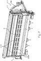
- Fig.1 shows a first embodiment of a cooling arrangement (or element) 200 comprising a cooling medium conduit 201 on two outer longitudinal sides of which two first cooling plate elements 210A, 210B are disposed, and which e.g. may be used for cooling a dual sided food bar arrangement.
- the cooling medium conduit 201 is provided with two inlets 202, 202 through which a cooling medium is introduced from a cooling system or a cooling apparatus that may be provided in an appropriate manner, and which may be of any known kind, e.g. comprising a compressor, an evaporator, a condenser etc. in a manner known per se.
- the invention is neither limited to any particular cooling system or apparatus, nor to the location thereof.
- the cooling medium circulates in the branch conduit 201, which also is provided with two (return) outlets 203, 203 arranged symmetrically with respect to the inlets, here at a slight distance from the inlets 202, 202, in a direction towards the center of longitudinal extension of the cooling medium conduit 201.
- the inlets and outlets are disposed in a symmetric manner, e.g. with respect to the center of the cooling medium conduit, and with respect to one another.
- the same amount of cooling medium is input to both, or each inlet 202, 202 to allow for an even distribution of cooling medium in the cooling medium conduit.
- the cooling medium in some embodiments is air, in other embodiments it may be a cooling liquid, e.g. comprising water or any appropriate cooling medium.
- the temperature of the cooling medium depends on the surrounding outer temperature, and on the temperature that is desired for the food bar or similar to be cooled. In some implementations, in which the cooling medium is air, or an air mixture, the temperature in the medium may be about -20°C. If the cooling medium is water based, the temperature could be about -3 or -4 °C. It should be clear that the invention is not limited to the specified temperatures, nor to any specific cooling medium, these being given merely for exemplifying reasons.
- the first cooling plate elements 210A, 210B comprise a plurality of internal flanges or ribs 211A, 211B extending in parallel, and a plurality of external cooling flanges 212A,212B extending in parallel in a direction substantially orthogonal to the longitudinal extension of the cooling medium conduit 201.
- the external flanges 212A, 212B are preferably arranged at a larger distance from each other than are the internal flanges 211A, 211B.
- One reason for that is that the larger distances between the external flanges facilitate cleaning, which normally is not required for the internal flanges facing the cooling medium conduit 201.
- the distance between adjacent external flanges is between 12 and 18 mm, particularly about 15 mm (peak-to-peak), whereas the distance between adjacent internal flanges (peak-to-peak) may be between ca. 5 and 8 mm.
- the distances may be larger as well as smaller; the same distances may be used for the external and the internal flanges etc.
- the external flanges are deeper, i.e. protrude a longer distance from its baseplate than the internal flanges do (in the opposite direction). One reason therefore is to not lose any cooling capacity due to the distance between the plate and the cooling medium conduit being too large.
- the external flanges may be deeper in order to further increase the effective area, which is a means to increase the transfer of cooling power from the cooling medium conduit to the food bar, or the products to be cooled.
- a cooling medium here air
- it holds a temperature of about -20°C.
- a plurality of openings e.g. circular holes 204 with a diameter of about 4-5 mm are disposed, cf. Fig. 2 .
- the openings may have other shapes than circular etc., of importance being that they are located in a symmetric manner along the upper edge of the cooling medium conduit 201.
- the cool air escaping through the openings 204 will flow downwards, along the outer side wall surfaces of the cooling medium conduit 201 (see Fig. 4 ), in the space formed between said outer surfaces and in "channels" formed by the internal flanges of the first cooling plate elements 210A, 210B which are disposed in parallel with the outer surfaces, at a small distance, or as close as possible.
- the cooling plate elements 210A, 210B will be more efficiently cooled by means of the cooling medium conduit, in other words the cooling transfer capacity will be enhanced. Further, due to the additional provisioning of the external flanges 212A, 212B, the effective area for cooling transfer on the outside is also increased. Thus, the transfer of cooling power from the cooling medium conduit 201 to the first cooling plate elements is increased due to the internal flanges 211A, 211B, and the transfer to outer side of the cooling plate elements is likewise increased due to the enhanced effective area obtained by means of the external flanges.
- the flanges may have the same size, shape and be arranged equidistantly throughout the entire area of a first cooling plate element, whereas in other embodiments it may be provided for an even more increased effective area e.g. along the outer side edges of the cooling plate elements where cooling losses may be larger due to a covering element being opened.
- This can be provided for in different manners, e.g. by means of flanges with a larger height, or deeper, and/or arranged at a smaller distance from each other etc.
- cooling plate elements can, in alternative embodiments be provided with a corrugated surface, or with fins, or formed so as to exhibit a large effective area towards the cooling medium conduit in many different manners.
- cooling transfer capacity may be increased from about 30% for state of the art arrangements up to about 70%.
- cooling medium conduit 201 on at least one side provided with a first cooling plate element as discussed above, an excellent optimal cooling transfer capacity is enabled. If the products are covered by a covering arrangement, cooling will be efficient also due to self-convection.
- the inner of the cooling medium conduit may be divided so as to comprise more than one flows of cooling medium, further contributing in reducing an uneven temperature distribution.
- a buffering of cold can be achieved as an additional means.
- only the inner surface areas of the cooling element plates are enhanced by means of flanges, or alternatively only the outer surface areas.
- the outer side of the cooling arrangement also denoted the cooling tower, should, in some preferred embodiments, have a temperature in the range of -3°C to +2°C.
- the flanges, ribs or fins preferably extend in parallel from the upper edge of the respective first cooling plate element to the lower edge, perpendicularly to the edges, forming parallel channels or in one alternative embodiment, forming a slight angle of one or a few degrees with a central line extending from the upper to the lower edge of the cooling medium conduit, symmetrically with respect to the upper edge midpoint, outwards to the outer side edges of the first cooling plate elements.
- the flanges or similar may also be slightly inclined or angled such that they are not quite symmetric, one side of a flange being somewhat more inclined, or shorter, than the other side.
- the flanges are preferably rounded, and the valleys between them also.
- the cooling plate elements may e.g. be made of aluminium, but also other materials are possible, including any metal or metal alloy or an appropriate plastic material.
- the first cooling plate elements 210A, 210B (and the outer side walls of the branch conduit 201) are in the shown embodiment arranged in a somewhat downwards, outwards slanting manner to give the air flowing on the outer sides an slight additional push, which is advantageous.
- the outer side walls of the branch conduit and the cooling plate elements may of course, alternatively, be entirely vertical.
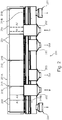
- Fig. 2 is a side view of the cooling medium conduit 201 with one first cooling plate element 210A removed. Elements already discussed with reference to Fig.1 bear the same reference numerals and will not be further discussed herein.
- the lower ends of the internal flanges 211B of the first cooling plate element 210B can be seen extending below the lower edge of the branch or cooling medium conduit 201.
- a row of equidistant openings 204 as discussed above are shown.
- the cooled air exiting the openings 204 flows downwards along the outer sides of the cooling medium conduit 201 as indicated by the dashed arrows A1, A2, wherein the arrow A2 indicates that cooled air flows also on the other side of the cooling medium conduit, exit openings being arranged also on the other upper side of the cooling medium conduit (if the cooling arrangement is to be used for dual sided cooling).
- Reference numeral 219 merely refer to any appropriate fastening means, e.g. screws and nuts, for connecting the first cooling plate elements 210A, 210B to the cooling medium conduit 201. Bars 218 or any appropriate means may be used to keep a desired distance, and push, the outer surface of the cooling medium conduit against the inner flanges 212A of the first cooling plate element 210A (not shown in Fig.2 ) .
- outlets 203, 203 The air exiting via outlets 203, 203 is recirculated to the cooling system.
- Optional air outlets 231 may be provided for directing cooled air, to provide for additional cooling, into a space under canteens or similar in a food bar, or to another part of a food bar, or to another cooling zone. These optional outlets 231 are not of significance for the functioning of the inventive concept, and may hence be disposed of.
- outlets/inlets alternatively may be reversed; i.e. the outlets 203 can function as inlets instead. Either a parallel flow or a counter flow heat exchanger may be used.
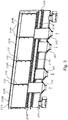
- Fig. 3 shows an inner side of an outer wall 201B of the cooling medium conduit 201, the opposite outer wall being removed for illustrative purposes. Similar elements are provided with the same reference numerals as in Figs. 1 and 2 .
- the openings 204B in the outer wall 201B are disposed in the same manner as the openings 204A in the other outer side wall 201B of the cooling medium conduit 201.
- the internal flanges 211B protruding below the lower edge of the cooling medium conduit 210B
- the external flanges 212B of the first cooling plate element 210B can be seen.
- the distance bars 218 are seen from the inside of the cooling medium conduit.
- a support and holding structure 215, 216 comprises a structure for holding the cooling arrangement 201, and comprises inlet and outlet conduits, and means for interconnecting the cooling arrangement 200 and a canteen holding arrangement or similar. It may have any appropriate form and also other dimensions than shown in the Figures. Particularly it may with advantage be made to have a smaller height; the pipes of the inlets and outlets 202, 203 then being shorter.
- Fig. 4 shows a cooling arrangement 200' according to another embodiment in which additional, second, cooling plate elements 220A', 220B' are disposed in parallel with, and outside, at a slight distance from, respective first cooling plate elements 210A', 210B'. The distance is substantially given by the height of the external flanges or rims or similar 212A', 212B'.
- the elements shown in Fig.4 correspond to the elements shown in Figs. 1-3 , and the corresponding reference numerals provided with a prime symbol are used. These elements will therefore not be further discussed here.
- the second cooling plate elements 220A', 220B' are in this embodiment provided with two rows, a lower and an upper row, of gills or fins 221A', 222A' opening up in an upward direction.
- the gills may have any appropriate shape and size, and may alternatively be arranged in more than two rows, or in any appropriate manner such that at least some gills are disposed at another distance from the upper/lower edge of the cooling medium conduit 201' than other gills.
- The may also be somewhat inclined to the right or to the left in Fig. 4 such that the center of the openings form an angle less than 90° with a line along the side walls, i.e. the respective second element plate, perpendicular to the upper and lower edges thereof.
- the gills or fins 221A', 222A' are fixed.
- they can be closable, i.e. they can be opened and closed respectively, manually or automatically.
- their positions are controllable, hence it may be possible to regulate their opening angle ⁇ .
- some of the gills are closable or controllable, for example if some regions require more cooling, the gills above such regions are opened up more and vice versa.
- the purpose of the second cooling plate elements 220A', 220B' is to further increase the self-convection over the canteens, under covering elements, and air will enter the gills from the space above e.g. a holding arrangement with canteens containing food products, and flow downwards, while being cooled when passing in the space, channels, between the inner sides of second cooling element plates 220A', 220B' and the external flanges 212A', 212B' of the first cooling plate elements 210A, 210B, providing an enlarged effective cooling area, which means that cooling transfer capacity will be most efficient.
- a covering arrangement comprising covering elements which are moved between an open and a closed position through being vertically displaced up and down, and which furthermore have rear walls ending at a position at an appropriate distance from the lower edges of side and front walls of the covering elements, in a closed position of the covering elements, the lower rows of gills 222A' will be exposed all the time, i.e. not covered by the rear section, allowing the entry of air, which will be cooled as explained above.
- a covering element When a covering element is opened, it will be moved upwards in a vertical direction, and also the gills 221A' which are located in the upper row will be uncovered, allowing the entry of air which will be refrigerated as discussed above, and will flow out over the canteens or similar, hence assisting in further compensating, in addition to the larger effective area of the cooling plate being uncovered, for losses in cooling capacity when the covering elements are opened, in that the self-convection will be even more stimulated, and more air will be refrigerated.
- a further advantage of using gills, is that radiation losses are reduced.
- auxiliary fans may optionally be provided at the upper side of the space between the first cooling plate elements 210A', 210B' and second cooling plate elements 220A', 220B' for pushing in additional air.
- the provisioning of such fans may be optional. In some embodiments there are no fans.
- fans are provided which can be activated when there is a need for additional cooling power, or for example under extreme conditions, such as a high surrounding temperature, or for products requiring a particularly low temperature.
- the outer walls of the cooling medium conduit are provided with a number of booster openings 224' with a diameter of about 2,5 - 3,5 mm, e.g. 3 mm, which however merely indicates an advantageous embodiment, see Fig. 5 , located below the row of openings (204', see also openings 204 Figs. 2 , 3 ), and corresponding openings 225', 226' in the first and second cooling plate elements, at a position which is located at the entry of a number of the upper gills 221A', 221B' to further enhance the cooling capacity.
- Fig. 5 is a very schematic view in cross-section of a cooling arrangement 200' as shown in Fig.4 .
- first cooling plate elements 210A', 210B' with internal and external flanges are provided. Cool air flows through openings 204', only very schematically indicated in Fig. 5 , along the outer side walls of the cooling medium conduit 201', whereas by means of the inner flanges the effective cooling area is enhanced, efficiently cooling the first cooling plate elements 210A', 210B', which via the external flanges provide a high cooling capacity in the channels formed on the outer sides.
- Arrows X indicate air flows returning to an evaporator of a cooling system.
- the booster openings 224' in the outer walls of the cooling medium conduit 201', and corresponding openings 225', 226' in the first and second cooling plate elements respectively additionally assist in cooling down the air entering the upper gills 221A', 221B' as discussed with reference to Fig. 4 .
- FIG. 5 the cross-section is taken through walls of the flanges and flows F1, F2 are schematically indicated although the actual flow channels between flanges cannot be seen.
- the cooling arrangement is used with a covering arrangement as disclosed in the Swedish patent application "A covering arrangement for a refrigerated food bar arrangement, and a food bar arrangement with such a covering arrangement" filed by the same applicant, and the content of which herewith is incorporated herein by reference, the lower gills 222A', 222B' are uncovered always allowing the entry of circulating air, whereas the upper gills are covered by a covering element when it is in a closed position, and uncovered when the covering element is opened, i.e. lifted up, hence also allowing circulating air to entry, possibly boosted in embodiments comprising booster openings 224'.
- Fig. 6 shows an alternative cooling arrangement 200" similar to the one described with reference to Figs. 4 and 5 , but with the difference that the second cooling plate elements 220A", 220B" do not comprise any gills.
- auxiliary fans can be provided above the "channels" provided between the first and second cooling plate elements to further increase the cooling capacity.
- Booster openings may optionally be provided in the outer wall of the cooling medium conduit and in the first cooling plate elements. In other aspects the functioning is similar to that described above with reference to the other embodiments.
- the second cooling pate elements may be made of Al, any other metal material, or of plastic.
- Fig. 7 schematically illustrates a cooling arrangement 200 as shown in Fig. 4 arranged in connection with a covering arrangement 110 comprising two covering elements (only one shown) 10B which is in a closed position.
- the covering arrangement is disclosed in the above mentioned Swedish patent application.
- a covering element When a covering element is brought to an open position, it is moved vertically upwards such that its lower edge will be located substantially as indicated through the dashed line U in Fig. 7 , hence, both rows of gills 221A', 222A' are uncovered, whereas in a closed position its lower edge will be located approximately as indicated by dashed line L in Fig.7 , hence covering the upper row of gills 221A'.
- Fig. 8 very schematically shows a cooling arrangement 200" as in Fig. 6 , i.e. which do not comprise any gills. It should however be clear, that in most advantageous embodiments, the second cooling plate elements do comprise gills.
- a cooling arrangement 110" does not have to be used in connection with a food bar as the one shown in the Fig.8 , but it can be used with any other food bar or also in other contexts when products, or anything else, need cooling. It should also be clear that a food bar does not have to be a dual food bar; it might just as well be a single sided food bar, in which case the cooling arrangement only comprises first (and second) cooling plate elements on one side.
- the cooling arrangement 200" is used in connection with a food bar arrangement 100 which comprises canteen holding arrangements 103A, 103B adapted to receive and hold a plurality of canteens 104 in which fresh food products are to be kept.
- the holding arrangements 103A, 103B are here provided in connection with a cupboard arrangement 300 comprising cold wells and being adapted to receive the canteens in such a manner that openings of the canteens make the food accessible for a customer from a first and a second outer side section of the holding arrangements 103A, 103B, hence allowing a customer to choose and pick from the canteens from two sides.
- the canteens are arranged in an outwards inclined manner, hence further contributing to the cooled air flowing outwards, downwards over the products in the canteens, and flowing upwards when it encounters the inner side of the covering element, and back towards the upper edge of the cooling arrangement.
- cooling arrangement according to the present invention with advantage also can be used irrespective of any particular covering arrangement, and for cooling different types of food bar arrangements or any other arrangement needing to be cooled.
- the cooling element arrangement 200" is arranged with respect to, or in, the holding arrangement 103 such that, when the canteens 104 are taken up therein, the canteen back walls will be located close to, facing it.
- the holding arrangement 103 is adapted to receive one or more rows of canteens 104, the cooling or refrigerating arrangement 200" protruding in a central portion of the bar arrangement to a height substantially in line with the upper edges of rear sections, or rear walls, of the covering elements 10A, 10B when they are in a closed position.
- the height of a rear section, in a mounted state of a covering element is smaller than that of its side sections since the refrigerating arrangement extends adjacent to the rear section, the purpose of the shorter dimension of the height of the rear section being to allow cooling by means of the cooling, refrigerating, arrangement as discussed above.
- the covering arrangement is arranged so as to leave a space above the canteens allowing air to circulate due to the cooled air flowing outwards (see arrows C in Fig. 8 ), (particularly somewhat downwards due to the inclination of the canteens in some embodiments) over the food, since cool air has a lower density.
- Fig. 9 very schematically illustrates a food bar arrangement 100' with a cooling arrangement 200' as described with reference to Fig. 4 , and with a covering arrangement 110 as disclosed in the earlier mentioned Swedish patent application.
- the gills 221A', 222A' are shown through the transparent front section of the covering element, and the front covering element is supposed to be in an open position such that the gills in both the upper and the lower rows are uncovered.
- the food bar arrangement also here comprises cupboards 300, and a machine room 400 is schematically illustrated in which e.g. an evaporator and a compressor of a cooling system may be provided which is in communication with the cooling arrangement 200', which however merely relates to an advantageous embodiment of a food bar arrangement in association with which a cooling arrangement of the present invention may be used.
- a machine room 400 is schematically illustrated in which e.g. an evaporator and a compressor of a cooling system may be provided which is in communication with the cooling arrangement 200', which however merely relates to an advantageous embodiment of a food bar arrangement in association with which a cooling arrangement of the present invention may be used.
Landscapes
- Engineering & Computer Science (AREA)
- Physics & Mathematics (AREA)
- Thermal Sciences (AREA)
- Chemical & Material Sciences (AREA)
- Combustion & Propulsion (AREA)
- Mechanical Engineering (AREA)
- General Engineering & Computer Science (AREA)
- Devices That Are Associated With Refrigeration Equipment (AREA)
Description
- The present invention relates to a cooling arrangement, e.g. for a food bar arrangement or similar, having the features of the first part of claim 1. The invention also relates to a cooling assembly according to the first part of claim 17, and to a food bar arrangement with such a cooling arrangement having the features of the first part of claim 19.
- In recent times it has become more and more popular to offer fresh food, salads, fruit vegetables, chicken, but also cooked and prepared food, or so called healthy food, from what often is called a salad bar, where the customer can pick and compose a meal from a number of different products kept in canteens or pans. However, since the food products may remain for some time in the canteens, which may be accessed by quite a large number of persons, the requirements as to an appropriate and hygienic storage capability are high. Furthermore the food products have to be kept under such conditions, and at such a temperature, that bacterial growth is prevented and the products can be kept fresh, appetizing and are not ruined or deteriorated in any way due to the storing.
- To be able to maintain an accurate temperature, e.g. above 0° (to avoid that the products be frozen), but below 8°C, several different arrangements have been proposed.
- Some known arrangements use cooling elements below the canteens, but it is difficult to obtain an even temperature distribution in the food stored in the canteens, i.e. throughout the canteens, independently of the location of the food and of the canteens. Covering arrangements used to cover and protect the canteens with content are frequently opened by customers accessing the food, each time during a shorter or a longer time period, which makes it even more difficult to obtain and maintain an even temperature distribution throughout the food bar.
- Known arrangements therefor also use fan blowers for blowing cold air onto the products e.g. from above, or from below or sideways onto the canteens. This is however not an entirely satisfactory solution for several reasons. First, it is not satisfactory from a hygienic point of view, bearing in mind that several individuals serve themselves from the canteens which means that air contaminated with bacteria etc. may be blown onto the food. Also other particles, e.g. dust may be blown onto the food. Second, due to the air flow, the food products may be dried out, and ruined, at least from an aesthetical point of view and the products will not look fresh, which may reduce the willingness of customers to buy and consume the products. Some articles may even loose taste and undergo unwanted changes.
- Examples of known cooling arrangements are disclosed in
US1909875A1 andEP1629750A1 . - These factors contribute in shortening the time period the products can be kept in the canteens, and they may have to be disposed of, even if they actually could have been stored for a longer time period, if stored under appropriate conditions.
- Third, it is a waste of energy to have fan blowers active all the time and it is difficult to keep an even temperature distribution. An uneven temperature distribution may also contribute to the production of harmful microorganisms.
- When covering arrangements or lids are opened to provide access to the food products, air of a higher temperature will enter the canteens, which means that even more cooling is required. If fans are used, the products will then be even more exposed to cool air, and the drying effect will be further increased, which means that the time period that the products can be stored in the food bar will be even shorter. In addition thereto, when the covering arrangements are opened, this will contribute to an even more uneven temperature distribution.
- The more often the food bar is accessed, i.e. the more often the cover is opened, the more difficult it will be to maintain an even temperature distribution, and the losses in cooling power will be further increased. In known arrangements the transfer of cooling power from a cooling arrangement may be as low as 30% or even less, the losses thus being considerable. There may also be a considerable spread in the cooling capacity in different parts of a cooling arrangement, or a cooling element, located close to products in e.g. a food bar, which results in it being extremely difficult to control the temperature in food bar canteens or similar holding the products, particularly if the allowed or desirable temperature interval within which the temperature may vary is small.
- It is therefore an object of the present invention to provide a cooling arrangement, particularly, but not exclusively, for a food bar arrangement, and as initially referred to, through which one or more of the above mentioned problems can be solved.
- A particular object is to provide a cooling arrangement through which a stable, even, temperature distribution can be provided, throughout the cooling arrangement itself, and also throughout the products to be cooled, e.g. kept in canteens or pans.
- It is a particular object to provide a cooling arrangement through which the refrigerating or cooling capacity is controllable or adjustable.
- It is further a particular object to provide a cooling arrangement through which losses in refrigerating or cooling capacity, particularly produced due to a covering arrangement being opened, e.g. to provide access to the products, can be reduced as compared to for known arrangements.
- It is also an object to provide a cooling arrangement through which an even temperature distribution in the products can be maintained also when covering elements of a covering arrangement are opened and closed.
- Still further it is an object to provide a cooling arrangement through which an increased cooling transfer capacity is provided as compared to known arrangements.
- Other particular objects are to provide a cooling arrangement which allows a reliable operation, which is easy to fabricate, install and mount, and which has excellent properties as far as maintenance and cleaning is concerned.
- Still further it is a particular object to provide a cooling arrangement which enables an efficient and controllable cooling of e.g. food products in a food bar without negatively affecting the products, e.g. by drying them out, and through which it is enabled that the products can be kept in the food bar in a safe and unaffected manner for a longer period of time than allowed for by arrangements which for example mainly are based on the use of air fans, but also than other arrangements.
- A particular object is also to provide a cooling arrangement through which high requirements on hygienic conditions can be fulfilled.
- It is also a particular object to provide a cooling arrangement which facilitates maintaining a stable, equal, temperature throughout the bar, or in some instances, even a variable or adaptable temperature for different regions in a holding arrangement holding products, also when they are accessed, i.e. when a covering element, a hood or a lid, is in an open position, or opened and closed frequently.
- A most particular object is to enable controlling of the temperature in a region to be cooled (e.g. in or above canteens) to be within a range of approximately 2°-4°C, which is difficult if the uneven temperature distribution in a cooling arrangement is between 1.5°-2°C or more, as is the case for most known arrangements.
- Still further it is an object to provide a cooling arrangement through which the need of using fans to achieve a sufficient refrigerating capacity can be eliminated, or reduced.
- Therefore a cooling arrangement as initially referred to is provided which has the characterizing features of claim 1.
- A cooling assembly comprising a cooling arrangement as initially referred to and a covering arrangement is also provided which has the characterizing features of claim 17.
- Another object of the invention is to provide a food bar arrangement with a cooling arrangement through which one or more of the above mentioned objects can be fulfilled.
- Therefore a food bar as initially referred to is provided which has the characterizing features of claim 19.
- A particular object is thereby to provide a high standard refrigerated food bar arrangement, particularly of the type intended for self-service, but also for other purposes, e.g. in canteens in schools or restaurants wherein staff are serving customers.
- It is also a particular object to provide a cooling arrangement which can be operated without, and particularly does not necessitate the use of, any fan blowers, or only to a limited extent, or which optionally can be used with or without fans, or with fans as an auxiliary equipment that may be activated or not.
- By means of a cooling arrangement according to the invention, it particularly becomes possible to control the cooling temperature to be between 2-4°C by enabling an even temperature distribution of the cooling arrangement only varies within an interval of about +/- 0.5°C, which is extremely advantageous.
- Advantageous embodiments are given by the respective appended sub-claims.
- The invention will in the following be further described in a non-limiting manner, and with reference to the accompanying drawings, in which:
- Fig. 1
- is a view in perspective of a cooling arrangement according to a first embodiment of the invention,
- Fig. 2
- is a side view showing a cooling medium conduit of the cooling arrangement shown in
Fig.1 , comprising two first cooling plate elements arranged in parallel for a dual sided food bar, and with one first cooling plate element, here the front cooling plate element, removed, - Fig. 3
- is a side view showing the rear, inner, side of a first cooling plate element of a cooling arrangement as shown in
Fig. 1 comprising two first cooling plate elements arranged in parallel for a dual sided food bar, and with one first cooling plate element, here the front cooling plate element, removed, - Fig. 4
- is a view in perspective of an advantageous embodiment of a cooling arrangement,
- Fig. 5
- is a schematic cross-sectional side view of the arrangement shown in
Fig.4 , - Fig. 6
- shows an alternative embodiment of a cooling arrangement,
- Fig. 7
- is a perspective view of a cooling arrangement according to one embodiment of the invention as arranged on the rear side of a covering element,
- Fig. 8
- is a very schematic view in perspective of a cooling arrangement as arranged between two covering elements of a covering arrangement for a dual sided food bar arrangement, and
- Fig. 9
- is a schematic view in perspective from above of a food bar arrangement with a cooling arrangement according to the invention.
-
Fig.1 shows a first embodiment of a cooling arrangement (or element) 200 comprising a coolingmedium conduit 201 on two outer longitudinal sides of which two firstcooling plate elements 210A, 210B are disposed, and which e.g. may be used for cooling a dual sided food bar arrangement. The coolingmedium conduit 201 is provided with twoinlets branch conduit 201, which also is provided with two (return)outlets inlets medium conduit 201. There could also have been any other number of inlets and outlets, depending on the length of the cooling medium conduit, and of the cooling arrangement. In order to enable the provisioning of an even temperature distribution, as will be further discussed below, it is of significance that the inlets and outlets are disposed in a symmetric manner, e.g. with respect to the center of the cooling medium conduit, and with respect to one another. - The same amount of cooling medium is input to both, or each
inlet - The cooling medium in some embodiments is air, in other embodiments it may be a cooling liquid, e.g. comprising water or any appropriate cooling medium. The temperature of the cooling medium depends on the surrounding outer temperature, and on the temperature that is desired for the food bar or similar to be cooled. In some implementations, in which the cooling medium is air, or an air mixture, the temperature in the medium may be about -20°C. If the cooling medium is water based, the temperature could be about -3 or -4 °C. It should be clear that the invention is not limited to the specified temperatures, nor to any specific cooling medium, these being given merely for exemplifying reasons.
- The first
cooling plate elements 210A, 210B comprise a plurality of internal flanges orribs external cooling flanges medium conduit 201. Theexternal flanges internal flanges medium conduit 201. In an advantageous embodiment the distance between adjacent external flanges is between 12 and 18 mm, particularly about 15 mm (peak-to-peak), whereas the distance between adjacent internal flanges (peak-to-peak) may be between ca. 5 and 8 mm. It should be clear that these figures merely are given for exemplifying reasons; the distances may be larger as well as smaller; the same distances may be used for the external and the internal flanges etc. In some embodiments the external flanges are deeper, i.e. protrude a longer distance from its baseplate than the internal flanges do (in the opposite direction). One reason therefore is to not lose any cooling capacity due to the distance between the plate and the cooling medium conduit being too large. However they are preferably much closer spaced as referred to above. The external flanges, however may be deeper in order to further increase the effective area, which is a means to increase the transfer of cooling power from the cooling medium conduit to the food bar, or the products to be cooled. - The functioning according to the invention is that a cooling medium, here air, is introduced to, and circulates in the cooling
medium conduit 201. In one embodiment it holds a temperature of about -20°C. Regularly spaced from one another, at a distance, e.g. 10-15 mm from the upper edge of thebranch conduit 201, and all along its upper edge in a symmetric manner, a plurality of openings, e.g.circular holes 204 with a diameter of about 4-5 mm are disposed, cf.Fig. 2 . It should be clear that the figures concerning diameter and distance etc. are merely given for exemplifying reasons. The distances between holes and their diameters or dimensions may be larger as well as smaller. In the shown embodiment they are arranged symmetrically in one row. In alternative embodiments it might of course be two or more rows, and/or the openings may have other shapes than circular etc., of importance being that they are located in a symmetric manner along the upper edge of the coolingmedium conduit 201. The cool air escaping through theopenings 204 will flow downwards, along the outer side wall surfaces of the cooling medium conduit 201 (seeFig. 4 ), in the space formed between said outer surfaces and in "channels" formed by the internal flanges of the firstcooling plate elements 210A, 210B which are disposed in parallel with the outer surfaces, at a small distance, or as close as possible. - Due to the provisioning of the internal flanges, i.e. the inner increased effective area, the cooling
plate elements 210A, 210B will be more efficiently cooled by means of the cooling medium conduit, in other words the cooling transfer capacity will be enhanced. Further, due to the additional provisioning of theexternal flanges medium conduit 201 to the first cooling plate elements is increased due to theinternal flanges - In different embodiments the flanges (internal and/or external) may have the same size, shape and be arranged equidistantly throughout the entire area of a first cooling plate element, whereas in other embodiments it may be provided for an even more increased effective area e.g. along the outer side edges of the cooling plate elements where cooling losses may be larger due to a covering element being opened. This can be provided for in different manners, e.g. by means of flanges with a larger height, or deeper, and/or arranged at a smaller distance from each other etc.
- It should be clear that the cooling plate elements can, in alternative embodiments be provided with a corrugated surface, or with fins, or formed so as to exhibit a large effective area towards the cooling medium conduit in many different manners.
- In advantageous embodiments as described above, it has been seen that the cooling transfer capacity may be increased from about 30% for state of the art arrangements up to about 70%.
- Through the arrangement of the cooling
medium conduit 201 on at least one side provided with a first cooling plate element as discussed above, an excellent optimal cooling transfer capacity is enabled. If the products are covered by a covering arrangement, cooling will be efficient also due to self-convection. - Thereby the need for using fans as a cooling means is reduced or eliminated, although fans may be implemented as an auxiliary or additional cooling means, which is extremely advantageous.
- In some embodiments the inner of the cooling medium conduit may be divided so as to comprise more than one flows of cooling medium, further contributing in reducing an uneven temperature distribution. By increasing the material thickness (e.g. metal) at desired locations in the cooling medium conduit, e.g. at the outer edges, or wherever needed, a buffering of cold can be achieved as an additional means.
- In some embodiments, only the inner surface areas of the cooling element plates are enhanced by means of flanges, or alternatively only the outer surface areas.
- The outer side of the cooling arrangement, also denoted the cooling tower, should, in some preferred embodiments, have a temperature in the range of -3°C to +2°C.
- The flanges, ribs or fins preferably extend in parallel from the upper edge of the respective first cooling plate element to the lower edge, perpendicularly to the edges, forming parallel channels or in one alternative embodiment, forming a slight angle of one or a few degrees with a central line extending from the upper to the lower edge of the cooling medium conduit, symmetrically with respect to the upper edge midpoint, outwards to the outer side edges of the first cooling plate elements.
- The flanges or similar may also be slightly inclined or angled such that they are not quite symmetric, one side of a flange being somewhat more inclined, or shorter, than the other side.
- The flanges are preferably rounded, and the valleys between them also. The cooling plate elements may e.g. be made of aluminium, but also other materials are possible, including any metal or metal alloy or an appropriate plastic material.
- The first
cooling plate elements 210A, 210B (and the outer side walls of the branch conduit 201) are in the shown embodiment arranged in a somewhat downwards, outwards slanting manner to give the air flowing on the outer sides an slight additional push, which is advantageous. The outer side walls of the branch conduit and the cooling plate elements may of course, alternatively, be entirely vertical. - The air flowing downwards between the outer surface of the cooling
medium conduit 201 and a respective first cooling plate element, i.e. in the channels formed by the internal flanges, for example flows back to an evaporator of a cooling system, and the air on the outside of the first cooling plate elements flows downwards, and out over the products, e.g. in canteens, such that air will flow due to self-convection if the products are located under a cover or similar. -
Fig. 2 is a side view of the coolingmedium conduit 201 with one first cooling plate element 210A removed. Elements already discussed with reference toFig.1 bear the same reference numerals and will not be further discussed herein. InFig. 2 the lower ends of theinternal flanges 211B of the firstcooling plate element 210B can be seen extending below the lower edge of the branch or coolingmedium conduit 201. At the upper edge of the cooling medium conduit 201 a row ofequidistant openings 204 as discussed above are shown. The cooled air exiting theopenings 204 flows downwards along the outer sides of the coolingmedium conduit 201 as indicated by the dashed arrows A1, A2, wherein the arrow A2 indicates that cooled air flows also on the other side of the cooling medium conduit, exit openings being arranged also on the other upper side of the cooling medium conduit (if the cooling arrangement is to be used for dual sided cooling).Reference numeral 219 merely refer to any appropriate fastening means, e.g. screws and nuts, for connecting the firstcooling plate elements 210A, 210B to the coolingmedium conduit 201.Bars 218 or any appropriate means may be used to keep a desired distance, and push, the outer surface of the cooling medium conduit against theinner flanges 212A of the first cooling plate element 210A (not shown inFig.2 ) . - The air exiting via
outlets Optional air outlets 231 may be provided for directing cooled air, to provide for additional cooling, into a space under canteens or similar in a food bar, or to another part of a food bar, or to another cooling zone. Theseoptional outlets 231 are not of significance for the functioning of the inventive concept, and may hence be disposed of. - It should be clear that the locations of outlets/inlets alternatively may be reversed; i.e. the
outlets 203 can function as inlets instead. Either a parallel flow or a counter flow heat exchanger may be used. -
Fig. 3 shows an inner side of anouter wall 201B of the coolingmedium conduit 201, the opposite outer wall being removed for illustrative purposes. Similar elements are provided with the same reference numerals as inFigs. 1 and2 . Theopenings 204B in theouter wall 201B are disposed in the same manner as the openings 204A in the otherouter side wall 201B of the coolingmedium conduit 201. InFig. 3 theinternal flanges 211B (protruding below the lower edge of the coolingmedium conduit 210B) and theexternal flanges 212B of the firstcooling plate element 210B can be seen. The distance bars 218 are seen from the inside of the cooling medium conduit. A support and holdingstructure cooling arrangement 201, and comprises inlet and outlet conduits, and means for interconnecting thecooling arrangement 200 and a canteen holding arrangement or similar. It may have any appropriate form and also other dimensions than shown in the Figures. Particularly it may with advantage be made to have a smaller height; the pipes of the inlets andoutlets - Through the arrangement of the cooling medium conduit and the cooling plate elements as disclosed according to the invention it becomes possible to achieve a very even temperature distribution all along the cooling arrangement.
-
Fig. 4 shows a cooling arrangement 200' according to another embodiment in which additional, second, coolingplate elements 220A', 220B' are disposed in parallel with, and outside, at a slight distance from, respective first cooling plate elements 210A', 210B'. The distance is substantially given by the height of the external flanges or rims or similar 212A', 212B'. In other respect the elements shown inFig.4 correspond to the elements shown inFigs. 1-3 , and the corresponding reference numerals provided with a prime symbol are used. These elements will therefore not be further discussed here. - The second
cooling plate elements 220A', 220B' are in this embodiment provided with two rows, a lower and an upper row, of gills orfins 221A', 222A' opening up in an upward direction. The gills may have any appropriate shape and size, and may alternatively be arranged in more than two rows, or in any appropriate manner such that at least some gills are disposed at another distance from the upper/lower edge of the cooling medium conduit 201' than other gills. The may also be somewhat inclined to the right or to the left inFig. 4 such that the center of the openings form an angle less than 90° with a line along the side walls, i.e. the respective second element plate, perpendicular to the upper and lower edges thereof. - In the shown embodiment the gills or
fins 221A', 222A' are fixed. In an alternative embodiment they can be closable, i.e. they can be opened and closed respectively, manually or automatically. In still another embodiment their positions are controllable, hence it may be possible to regulate their opening angle β. In a particular embodiment some of the gills are closable or controllable, for example if some regions require more cooling, the gills above such regions are opened up more and vice versa. - The purpose of the second
cooling plate elements 220A', 220B' is to further increase the self-convection over the canteens, under covering elements, and air will enter the gills from the space above e.g. a holding arrangement with canteens containing food products, and flow downwards, while being cooled when passing in the space, channels, between the inner sides of secondcooling element plates 220A', 220B' and theexternal flanges 212A', 212B' of the firstcooling plate elements 210A, 210B, providing an enlarged effective cooling area, which means that cooling transfer capacity will be most efficient. As will be further described with reference toFig. 7 below, if used with a covering arrangement comprising covering elements which are moved between an open and a closed position through being vertically displaced up and down, and which furthermore have rear walls ending at a position at an appropriate distance from the lower edges of side and front walls of the covering elements, in a closed position of the covering elements, the lower rows ofgills 222A' will be exposed all the time, i.e. not covered by the rear section, allowing the entry of air, which will be cooled as explained above. When a covering element is opened, it will be moved upwards in a vertical direction, and also thegills 221A' which are located in the upper row will be uncovered, allowing the entry of air which will be refrigerated as discussed above, and will flow out over the canteens or similar, hence assisting in further compensating, in addition to the larger effective area of the cooling plate being uncovered, for losses in cooling capacity when the covering elements are opened, in that the self-convection will be even more stimulated, and more air will be refrigerated. - A further advantage of using gills, is that radiation losses are reduced.
- Thus, when more cooling is needed, more cooling is automatically provided without increasing cooling power capacity from any cooling system or similar. In some cases auxiliary fans may optionally be provided at the upper side of the space between the first cooling plate elements 210A', 210B' and second
cooling plate elements 220A', 220B' for pushing in additional air. The provisioning of such fans may be optional. In some embodiments there are no fans. - In some embodiments fans are provided which can be activated when there is a need for additional cooling power, or for example under extreme conditions, such as a high surrounding temperature, or for products requiring a particularly low temperature.
- In a particular embodiment the outer walls of the cooling medium conduit are provided with a number of booster openings 224' with a diameter of about 2,5 - 3,5 mm, e.g. 3 mm, which however merely indicates an advantageous embodiment, see
Fig. 5 , located below the row of openings (204', see alsoopenings 204Figs. 2 ,3 ), and corresponding openings 225', 226' in the first and second cooling plate elements, at a position which is located at the entry of a number of theupper gills 221A', 221B' to further enhance the cooling capacity. In one embodiment there are eight such booster openings 224' (225', 226') on each outer side wall. There may of course be more as well as fewer; they may be equidistantly disposed, or only in the regions of the outer side edges, or wherever an even more increased cooling capacity is needed. -
Fig. 5 is a very schematic view in cross-section of a cooling arrangement 200' as shown inFig.4 . On both sides of a cooling medium conduit 201' first cooling plate elements 210A', 210B' with internal and external flanges are provided. Cool air flows through openings 204', only very schematically indicated inFig. 5 , along the outer side walls of the cooling medium conduit 201', whereas by means of the inner flanges the effective cooling area is enhanced, efficiently cooling the first cooling plate elements 210A', 210B', which via the external flanges provide a high cooling capacity in the channels formed on the outer sides. Air entering via the gill openings via self-convection, arrows C1, C2, is further cooled in the space or the channels formed by the external flanges, and flows out, arrows D, over canteens or similar, not shown, hence cooling the products therein. Arrows X indicate air flows returning to an evaporator of a cooling system. InFig. 5 the booster openings 224' in the outer walls of the cooling medium conduit 201', and corresponding openings 225', 226' in the first and second cooling plate elements respectively, additionally assist in cooling down the air entering theupper gills 221A', 221B' as discussed with reference toFig. 4 . - In
Fig. 5 the cross-section is taken through walls of the flanges and flows F1, F2 are schematically indicated although the actual flow channels between flanges cannot be seen. - If the cooling arrangement is used with a covering arrangement as disclosed in the Swedish patent application "A covering arrangement for a refrigerated food bar arrangement, and a food bar arrangement with such a covering arrangement" filed by the same applicant, and the content of which herewith is incorporated herein by reference, the
lower gills 222A', 222B' are uncovered always allowing the entry of circulating air, whereas the upper gills are covered by a covering element when it is in a closed position, and uncovered when the covering element is opened, i.e. lifted up, hence also allowing circulating air to entry, possibly boosted in embodiments comprising booster openings 224'. -
Fig. 6 shows analternative cooling arrangement 200" similar to the one described with reference toFigs. 4 and5 , but with the difference that the secondcooling plate elements 220A", 220B" do not comprise any gills. In such a case preferably, although not necessarily, auxiliary fans can be provided above the "channels" provided between the first and second cooling plate elements to further increase the cooling capacity. Booster openings may optionally be provided in the outer wall of the cooling medium conduit and in the first cooling plate elements. In other aspects the functioning is similar to that described above with reference to the other embodiments. - The second cooling pate elements, with or without gills, may be made of Al, any other metal material, or of plastic.
-
Fig. 7 schematically illustrates acooling arrangement 200 as shown inFig. 4 arranged in connection with acovering arrangement 110 comprising two covering elements (only one shown) 10B which is in a closed position. The covering arrangement is disclosed in the above mentioned Swedish patent application. When a covering element is brought to an open position, it is moved vertically upwards such that its lower edge will be located substantially as indicated through the dashed line U inFig. 7 , hence, both rows ofgills 221A', 222A' are uncovered, whereas in a closed position its lower edge will be located approximately as indicated by dashed line L inFig.7 , hence covering the upper row ofgills 221A'. - The air flow due to self-convection under the
covering element 10B over the canteens (not shown) is illustrated by means of a dashed arrow. -
Fig. 8 very schematically shows acooling arrangement 200" as inFig. 6 , i.e. which do not comprise any gills. It should however be clear, that in most advantageous embodiments, the second cooling plate elements do comprise gills. - It should be clear that a
cooling arrangement 110" according to the invention does not have to be used in connection with a food bar as the one shown in theFig.8 , but it can be used with any other food bar or also in other contexts when products, or anything else, need cooling. It should also be clear that a food bar does not have to be a dual food bar; it might just as well be a single sided food bar, in which case the cooling arrangement only comprises first (and second) cooling plate elements on one side. - However, in the particular illustrated embodiment, the
cooling arrangement 200" is used in connection with afood bar arrangement 100 which comprisescanteen holding arrangements canteens 104 in which fresh food products are to be kept. - The holding
arrangements cupboard arrangement 300 comprising cold wells and being adapted to receive the canteens in such a manner that openings of the canteens make the food accessible for a customer from a first and a second outer side section of the holdingarrangements - It should be clear that the cooling arrangement according to the present invention with advantage also can be used irrespective of any particular covering arrangement, and for cooling different types of food bar arrangements or any other arrangement needing to be cooled.
- The
cooling element arrangement 200" is arranged with respect to, or in, the holding arrangement 103 such that, when thecanteens 104 are taken up therein, the canteen back walls will be located close to, facing it. - In the advantageous embodiment shown in
Fig. 8 the holding arrangement 103 is adapted to receive one or more rows ofcanteens 104, the cooling or refrigeratingarrangement 200" protruding in a central portion of the bar arrangement to a height substantially in line with the upper edges of rear sections, or rear walls, of thecovering elements - The height of a rear section, in a mounted state of a covering element, is smaller than that of its side sections since the refrigerating arrangement extends adjacent to the rear section, the purpose of the shorter dimension of the height of the rear section being to allow cooling by means of the cooling, refrigerating, arrangement as discussed above. When a covering element is lifted or elevated to the open position, a larger area of the cooling element will be exposed or uncovered, thus at least to a considerable extent compensating for the warmer air entering the space above the canteens when the
covering element 10B is in an open position. - The covering arrangement is arranged so as to leave a space above the canteens allowing air to circulate due to the cooled air flowing outwards (see arrows C in
Fig. 8 ), (particularly somewhat downwards due to the inclination of the canteens in some embodiments) over the food, since cool air has a lower density. -
Fig. 9 very schematically illustrates a food bar arrangement 100' with a cooling arrangement 200' as described with reference toFig. 4 , and with acovering arrangement 110 as disclosed in the earlier mentioned Swedish patent application. InFig. 9 thegills 221A', 222A' are shown through the transparent front section of the covering element, and the front covering element is supposed to be in an open position such that the gills in both the upper and the lower rows are uncovered. - The food bar arrangement also here comprises
cupboards 300, and amachine room 400 is schematically illustrated in which e.g. an evaporator and a compressor of a cooling system may be provided which is in communication with the cooling arrangement 200', which however merely relates to an advantageous embodiment of a food bar arrangement in association with which a cooling arrangement of the present invention may be used. - It should be clear that the invention is not limited to the specifically illustrated embodiments, but that it can be varied in a number of ways within the scope of the appended claims.
Claims (17)
- A cooling arrangement (200;200';200") for a food bar arrangement or similar holding products needing to be cooled, wherein the cooling arrangement (200;200';200") comprises a cooling medium conduit (201;201';201") with a number of cooling medium inlets (202,202), the cooling arrangement further comprising a number of cooling medium Outlets (203, 203), characterized in that the cooling medium inlets (202,202) and the cooling medium outlets (203,203) are disposed symmetrically along the cooling medium conduit (201;201';201") which comprises at least one side wall (201A,201B;201A',201B';201A",201B"), said at least one side wall comprising a plurality of openings, e.g. circular holes, (204,204A,204B) disposed along an upper edge of said at least one side wall allowing cool air to exit through said openings (204,204A,204B),
that adjacent, and in parallel, with said outer wall at least a first cooling plate element (210A, 210B;210A', 210B' ; 210A",210B") is disposed,
that said first cooling plate element (210A,210B; 210A',210B';210A",210B") comprises internal flanges, ribs or similar (211A,211B; 211A',211B';211A",211B") provided on an inner side of said first cooling plate element (210A,210B;210A',210B';210A",210B") facing the cooling medium conduit (201), and/or external flanges (212A,212B;212A',212B'; 212A",212B") provided on the outer side of said first cooling plate element (210A, 210B;210A', 210B';210A", 210B") to enhance the effective area of said first cooling plate element (210A,210B;210A',210B';210A",210B"), to increase the cooling power transfer capacity from the cooling medium conduit, and to allow air escaping through said openings (204) to flow in the space between the cooling medium conduit (201;201';201") and the first cooling plate element (210A,210B; 210A', 210B'; 210A", 210B"). - A cooling arrangement according to claim 1,
characterized in that
said at least one first cooling plate element (210A,210B;210A', 210B';210A", 210B") comprises a plurality of internal flanges (211A,211B;211A',211B';211A",211B") extending in parallel from an upper edge towards a lower edge of said first cooling plate element (210A,210B;210A',210B';210A",210B"), said internal flanges (211A,211B;211A',211B';211A",211B") being arranged on a side of the first cooling plate element facing the cooling medium conduit (201;201';201"), wherein the distance between the first cooling plate element (210A, 210B;210A', 210B';210A", 210B") and the cooling medium conduit (201;201201") substantially is given by a height of said internal flanges (211A,211B;211A',211B';211A",211B"), i.e. the distance they protrude, allowing air exiting the openings or through holes (204, 204A,204B), to flow downwards in channels formed by said internal flanges (211A,211B;211A',211B';211A",211B"). - A cooling arrangement according to claim 1 or 2,
characterized in that
said first cooling plate element (210A,210B;210A',210B';210A", 210B") comprises external flanges, ribs or similar (212A,212B; 212A',212B';212A",212B") arranged on a side of the first cooling plate element (210A,210B;210A',210B';210A", 210B") facing away from the cooling medium conduit (201;201';201"), hence being adapted to increase the effective cooling area on the outside of said first cooling plate element (210A,210B;210A',210B';210A", 210B") . - A cooling arrangement at least according to claim 2,
characterized in that
the distance between adjacent internal flanges (211A,211B;211A',211B';211A",211B") is about 5-8 mm, and/or that the distance between adjacent external flanges (212A,212B; 212A',212B';212A",212B") is about 12-18 mm. - A cooling arrangement at least according to claim 2 and 3,
characterized in that
the external flanges (212A,212B; 212A',212B';212A",212B") protrude a distance which is longer than the distance that the internal flanges (211A,211B;211A',211B';211A",211B") protrude. - A cooling arrangement according to any one of the preceding claims,
characterized in that
the internal flanges (211A,211B;211A',211B';211A",211B") are equidistantly disposed and/or that the external flanges (212A,212B; 212A',212B';212A",212B") are equidistantly disposed. - A cooling arrangement according to any one of the preceding claims,
characterized in that
it further comprises at least one second cooling plate element (220A',220B';220A",220B") disposed in parallel with said first cooling plate element (210A',210B';210A",210B") on its side facing away from the cooling medium conduit (201';201"). - A cooling arrangement according to claim 7,
characterized in that
the second cooling plate element (220A',220B';220A",220B") comprises a plurality of gills or fins (221A',221B',222A',222B') having openings which are substantially directed upwards in a mounted state of the cooling arrangement and adapted to allow air to entry through said gills (221A',221B',222A',222B'), and to flow downwards in channels formed by the external flanges of the first cooling plate element (210A',210B';210A",210B"), in a space between the first cooling plate element and said second cooling plate element (220A',220B';220A",220B") while being cooled, and to flow out at lower edges of said second cooling plate element (220A',220B';220A",220B") over products or similar to be cooled, for example canteens or similar arranged in holding means, and being located in connection with said lower edge, such that said products are cooled. - A cooling arrangement according to claim 8,
characterized in that
the gills (221A',221B',222A',222B') are disposed at an upper section of said second cooling plate element (220A',220B';220A",220B"), and that the gills (221A',221B',222A',222B') are disposed so as to be located at least two different distances from the upper edge of said second cooling plate element (220A',220B';220A",220B"), preferably disposed in two parallel rows. - A cooling arrangement according to claim 8 or 9,
characterized in that
at least some of the gills (221A',221B',222A',222B') are adapted to be openable /closable and that they automatically or manually can be closed or opened, and/or that at least some of the gills (221A',221B',222A',222B') are adapted to be openable to a controllable extent, by means of a controllable opening angle (β). - A cooling arrangement according to any one of the preceding claims,
characterized in that
the outer wall (s) of the cooling medium conduit (201;201';201") comprises booster openings (224A',224B') disposed below said openings (204; 204A,204B;204") which are constantly open or adapted to be openable/closable in a controlled manner, and in that also said first cooling plate element, or said first cooling plate element and second cooling plate element, if provided, is/are provided with corresponding through booster openings (225B', 226B') to further enhance cooling capacity by allowing cooled air to flow directly from the cooling medium conduit through said booster openings out to the outer side of the cooling arrangement. - A cooling arrangement at least according to claim 9,
characterized in that
one or more fans are provided above the upper edges of the first and/or the second cooling plate elements to further increase the cooling capacity, said fans being adapted to be able to optionally be switched on/switched off. - A cooling arrangement according to any one of the preceding claims,
characterized in that
it comprises two first cooling plate elements arranged on opposite sides of said cooling medium conduit (201,201',201"), or first and second cooling plate elements disposed on two sides of said cooling medium conduit hence being adapted for cooling on two opposite sides. - A cooling assembly,
characterized in that
it comprises a cooling arrangement (200;200';200") according to any one of claims 1-13 and at least one covering arrangement (110) comprising at least one covering element (10A,10B) comprising a rear section and a front section, wherein said rear section has a lower edge which ends, in a mounted state of the assembly, at a shorter distance from an upper edge than said front section, said upper edges being joined, and in that said covering arrangement (110) and said cooling arrangement (200;200';200") are so arranged with respect to one another that said rear section faces the outermost first or second cooling plate element, and in that said covering element (10A,10B) is adapted to be opened and closed respectively by means of a vertical movement, such that a larger area, providing an enhanced cooling capacity, of said outermost cooling plate element is uncovered when the covering element (10A,10B) is in an opened position hence compensating for cooling losses due to opening of the covering element (10A,10B), and in that in a closed position, a smaller area of the outermost of said cooling plate elements is uncovered. - A cooling assembly according to claim 14,
characterized in that
the cooling arrangement (200;200';200") comprises at least one second cooling plate element (220A',220B';220A",220B") which is provided with gills (221A', 221B', 222A', 222B') arranged in at least an upper and a lower row, and in that when the covering element (10B) is in an open position, both rows of gills are uncovered, whereas when it is in a closed position, only one row is uncovered. - A food bar arrangement (100),
characterized in that
it is provided with a cooling arrangement as in any one of claims 1-13. - A food bar arrangement according to claim 16,
characterized in that
it is provided with a cooling assembly according to claim 14 or 15, and in that it comprises a single sided or a dual-sided food bar.
Applications Claiming Priority (2)
| Application Number | Priority Date | Filing Date | Title |
|---|---|---|---|
| SE1450665A SE539546C2 (en) | 2014-06-02 | 2014-06-02 | A cooling device and a food bar device having such a cooling device |
| PCT/SE2015/050533 WO2015187075A1 (en) | 2014-06-02 | 2015-05-12 | A cooling arrangement, a cooling assembly and a food bar arrangement comprising such a cooling arrangement |
Publications (3)
| Publication Number | Publication Date |
|---|---|
| EP3148382A1 EP3148382A1 (en) | 2017-04-05 |
| EP3148382A4 EP3148382A4 (en) | 2018-01-17 |
| EP3148382B1 true EP3148382B1 (en) | 2018-12-26 |
Family
ID=54767040
Family Applications (1)
| Application Number | Title | Priority Date | Filing Date |
|---|---|---|---|
| EP15803716.8A Active EP3148382B1 (en) | 2014-06-02 | 2015-05-12 | A cooling arrangement, a cooling assembly and a food bar arrangement comprising such a cooling arrangement |
Country Status (4)
| Country | Link |
|---|---|
| EP (1) | EP3148382B1 (en) |
| DK (1) | DK3148382T3 (en) |
| SE (1) | SE539546C2 (en) |
| WO (1) | WO2015187075A1 (en) |
Family Cites Families (6)
| Publication number | Priority date | Publication date | Assignee | Title |
|---|---|---|---|---|
| US1909875A (en) * | 1929-08-31 | 1933-05-16 | Devon Mfg Company | Refrigerator |
| US5168719A (en) * | 1991-12-24 | 1992-12-08 | Specialty Equipment Companies, Inc. | Food preparation table with open air food storage |
| KR19990017123A (en) * | 1997-08-21 | 1999-03-15 | 남해석 | Exhibit Preservation Device |
| US7062932B2 (en) * | 2004-08-24 | 2006-06-20 | Hussmann Corporation | Refrigerated merchandiser with fan-powered rear discharge |
| KR101466658B1 (en) * | 2007-10-09 | 2014-11-28 | 삼성전자 주식회사 | Refrigerator |
| CN201170681Y (en) * | 2008-05-12 | 2008-12-24 | 上海海立中野冷机有限公司 | Freezing refrigerated shelf type showcase and back face air duct structure thereof |
-
2014
- 2014-06-02 SE SE1450665A patent/SE539546C2/en unknown
-
2015
- 2015-05-12 EP EP15803716.8A patent/EP3148382B1/en active Active
- 2015-05-12 WO PCT/SE2015/050533 patent/WO2015187075A1/en not_active Ceased
- 2015-05-12 DK DK15803716.8T patent/DK3148382T3/en active
Non-Patent Citations (1)
| Title |
|---|
| None * |
Also Published As
| Publication number | Publication date |
|---|---|
| EP3148382A1 (en) | 2017-04-05 |
| SE1450665A1 (en) | 2015-12-03 |
| SE539546C2 (en) | 2017-10-10 |
| WO2015187075A1 (en) | 2015-12-10 |
| EP3148382A4 (en) | 2018-01-17 |
| DK3148382T3 (en) | 2019-04-01 |
Similar Documents
| Publication | Publication Date | Title |
|---|---|---|
| EP3148380B1 (en) | An improved refrigerated food bar arrangement | |
| JP6616766B2 (en) | Improvements in refrigerated display equipment or improvements in refrigerated display equipment | |
| US20010003248A1 (en) | Airflow arrangement for a refrigerator | |
| AU2014264369B2 (en) | Improvements in or relating to refrigerated display appliances | |
| EP3474706B1 (en) | Display unit for storing and displaying heated goods, and use of such a display unit | |
| CN108294556B (en) | Vertical open type refrigerated display cabinet with special air duct | |
| WO2011121285A1 (en) | Improvements in or relating to refrigerated display appliances | |
| DK3148382T3 (en) | Refrigerator, refrigerator and food counter with such refrigerator | |
| RU2759646C2 (en) | Cooled counter-showcase and corresponding system of distribution of cooled air flow | |
| US20020047506A1 (en) | Refrigerator shelf | |
| EP3037022B1 (en) | Refrigerated display cabinet | |
| EP2975974B1 (en) | A refrigerated food bar arrangement | |
| JP2018084391A (en) | Cooling unit and walk-in type showcase including the same | |
| JP4923972B2 (en) | Showcase | |
| EP1853139B1 (en) | Refridgerated display chest | |
| GB2466990A (en) | Refrigerated food storage unit with a baffle plate to disperse air flow evenly across a chilling unit | |
| EP1486148A1 (en) | Refrigerated display cabinets | |
| RU2125211C1 (en) | Air distribution system for loaded room | |
| JP2015150041A (en) | open showcase | |
| JP2006023003A (en) | Open showcase | |
| JP2007064527A (en) | Open showcase | |
| JPH0370966A (en) | Cold air circulating showcase | |
| CZ2007613A3 (en) | Refrigerated show cabinet for loading from the rear side | |
| JP2017074292A (en) | Open showcase |
Legal Events
| Date | Code | Title | Description |
|---|---|---|---|
| STAA | Information on the status of an ep patent application or granted ep patent |
Free format text: STATUS: THE INTERNATIONAL PUBLICATION HAS BEEN MADE |
|
| PUAI | Public reference made under article 153(3) epc to a published international application that has entered the european phase |
Free format text: ORIGINAL CODE: 0009012 |
|
| STAA | Information on the status of an ep patent application or granted ep patent |
Free format text: STATUS: REQUEST FOR EXAMINATION WAS MADE |
|
| 17P | Request for examination filed |
Effective date: 20161206 |
|
| AK | Designated contracting states |
Kind code of ref document: A1 Designated state(s): AL AT BE BG CH CY CZ DE DK EE ES FI FR GB GR HR HU IE IS IT LI LT LU LV MC MK MT NL NO PL PT RO RS SE SI SK SM TR |
|
| AX | Request for extension of the european patent |
Extension state: BA ME |
|
| DAV | Request for validation of the european patent (deleted) | ||
| DAX | Request for extension of the european patent (deleted) | ||
| A4 | Supplementary search report drawn up and despatched |
Effective date: 20171220 |
|
| RIC1 | Information provided on ipc code assigned before grant |
Ipc: F25D 17/06 20060101ALI20171214BHEP Ipc: F25D 11/02 20060101ALI20171214BHEP Ipc: A47F 10/06 20060101ALI20171214BHEP Ipc: A47B 31/02 20060101ALI20171214BHEP Ipc: F25D 17/08 20060101ALI20171214BHEP Ipc: A47F 3/04 20060101AFI20171214BHEP |
|
| GRAP | Despatch of communication of intention to grant a patent |
Free format text: ORIGINAL CODE: EPIDOSNIGR1 |
|
| STAA | Information on the status of an ep patent application or granted ep patent |
Free format text: STATUS: GRANT OF PATENT IS INTENDED |
|
| RIC1 | Information provided on ipc code assigned before grant |
Ipc: A47F 3/04 20060101AFI20180821BHEP Ipc: F25D 17/06 20060101ALI20180821BHEP Ipc: A47F 10/06 20060101ALI20180821BHEP Ipc: F25D 11/02 20060101ALI20180821BHEP Ipc: A47B 31/02 20060101ALI20180821BHEP Ipc: F25D 17/08 20060101ALI20180821BHEP |
|
| INTG | Intention to grant announced |
Effective date: 20180913 |
|
| GRAJ | Information related to disapproval of communication of intention to grant by the applicant or resumption of examination proceedings by the epo deleted |
Free format text: ORIGINAL CODE: EPIDOSDIGR1 |
|
| STAA | Information on the status of an ep patent application or granted ep patent |
Free format text: STATUS: REQUEST FOR EXAMINATION WAS MADE |
|
| GRAR | Information related to intention to grant a patent recorded |
Free format text: ORIGINAL CODE: EPIDOSNIGR71 |
|
| GRAS | Grant fee paid |
Free format text: ORIGINAL CODE: EPIDOSNIGR3 |
|
| STAA | Information on the status of an ep patent application or granted ep patent |
Free format text: STATUS: GRANT OF PATENT IS INTENDED |
|
| GRAA | (expected) grant |
Free format text: ORIGINAL CODE: 0009210 |
|
| STAA | Information on the status of an ep patent application or granted ep patent |
Free format text: STATUS: THE PATENT HAS BEEN GRANTED |
|
| INTC | Intention to grant announced (deleted) | ||
| INTG | Intention to grant announced |
Effective date: 20181114 |
|
| AK | Designated contracting states |
Kind code of ref document: B1 Designated state(s): AL AT BE BG CH CY CZ DE DK EE ES FI FR GB GR HR HU IE IS IT LI LT LU LV MC MK MT NL NO PL PT RO RS SE SI SK SM TR |
|
| REG | Reference to a national code |
Ref country code: GB Ref legal event code: FG4D |
|
| REG | Reference to a national code |
Ref country code: CH Ref legal event code: EP |
|
| REG | Reference to a national code |
Ref country code: AT Ref legal event code: REF Ref document number: 1080241 Country of ref document: AT Kind code of ref document: T Effective date: 20190115 |
|
| REG | Reference to a national code |
Ref country code: DE Ref legal event code: R096 Ref document number: 602015022488 Country of ref document: DE |
|
| REG | Reference to a national code |
Ref country code: IE Ref legal event code: FG4D |
|
| REG | Reference to a national code |
Ref country code: DK Ref legal event code: T3 Effective date: 20190325 |
|
| PG25 | Lapsed in a contracting state [announced via postgrant information from national office to epo] |
Ref country code: LV Free format text: LAPSE BECAUSE OF FAILURE TO SUBMIT A TRANSLATION OF THE DESCRIPTION OR TO PAY THE FEE WITHIN THE PRESCRIBED TIME-LIMIT Effective date: 20181226 Ref country code: LT Free format text: LAPSE BECAUSE OF FAILURE TO SUBMIT A TRANSLATION OF THE DESCRIPTION OR TO PAY THE FEE WITHIN THE PRESCRIBED TIME-LIMIT Effective date: 20181226 Ref country code: NO Free format text: LAPSE BECAUSE OF FAILURE TO SUBMIT A TRANSLATION OF THE DESCRIPTION OR TO PAY THE FEE WITHIN THE PRESCRIBED TIME-LIMIT Effective date: 20190326 Ref country code: BG Free format text: LAPSE BECAUSE OF FAILURE TO SUBMIT A TRANSLATION OF THE DESCRIPTION OR TO PAY THE FEE WITHIN THE PRESCRIBED TIME-LIMIT Effective date: 20190326 Ref country code: HR Free format text: LAPSE BECAUSE OF FAILURE TO SUBMIT A TRANSLATION OF THE DESCRIPTION OR TO PAY THE FEE WITHIN THE PRESCRIBED TIME-LIMIT Effective date: 20181226 |
|
| REG | Reference to a national code |
Ref country code: NL Ref legal event code: MP Effective date: 20181226 |
|
| REG | Reference to a national code |
Ref country code: LT Ref legal event code: MG4D |
|
| PG25 | Lapsed in a contracting state [announced via postgrant information from national office to epo] |
Ref country code: GR Free format text: LAPSE BECAUSE OF FAILURE TO SUBMIT A TRANSLATION OF THE DESCRIPTION OR TO PAY THE FEE WITHIN THE PRESCRIBED TIME-LIMIT Effective date: 20190327 Ref country code: AL Free format text: LAPSE BECAUSE OF FAILURE TO SUBMIT A TRANSLATION OF THE DESCRIPTION OR TO PAY THE FEE WITHIN THE PRESCRIBED TIME-LIMIT Effective date: 20181226 Ref country code: SE Free format text: LAPSE BECAUSE OF FAILURE TO SUBMIT A TRANSLATION OF THE DESCRIPTION OR TO PAY THE FEE WITHIN THE PRESCRIBED TIME-LIMIT Effective date: 20181226 Ref country code: RS Free format text: LAPSE BECAUSE OF FAILURE TO SUBMIT A TRANSLATION OF THE DESCRIPTION OR TO PAY THE FEE WITHIN THE PRESCRIBED TIME-LIMIT Effective date: 20181226 |
|
| REG | Reference to a national code |
Ref country code: AT Ref legal event code: MK05 Ref document number: 1080241 Country of ref document: AT Kind code of ref document: T Effective date: 20181226 |
|
| PG25 | Lapsed in a contracting state [announced via postgrant information from national office to epo] |
Ref country code: NL Free format text: LAPSE BECAUSE OF FAILURE TO SUBMIT A TRANSLATION OF THE DESCRIPTION OR TO PAY THE FEE WITHIN THE PRESCRIBED TIME-LIMIT Effective date: 20181226 |
|
| PG25 | Lapsed in a contracting state [announced via postgrant information from national office to epo] |
Ref country code: PT Free format text: LAPSE BECAUSE OF FAILURE TO SUBMIT A TRANSLATION OF THE DESCRIPTION OR TO PAY THE FEE WITHIN THE PRESCRIBED TIME-LIMIT Effective date: 20190426 Ref country code: PL Free format text: LAPSE BECAUSE OF FAILURE TO SUBMIT A TRANSLATION OF THE DESCRIPTION OR TO PAY THE FEE WITHIN THE PRESCRIBED TIME-LIMIT Effective date: 20181226 Ref country code: ES Free format text: LAPSE BECAUSE OF FAILURE TO SUBMIT A TRANSLATION OF THE DESCRIPTION OR TO PAY THE FEE WITHIN THE PRESCRIBED TIME-LIMIT Effective date: 20181226 Ref country code: CZ Free format text: LAPSE BECAUSE OF FAILURE TO SUBMIT A TRANSLATION OF THE DESCRIPTION OR TO PAY THE FEE WITHIN THE PRESCRIBED TIME-LIMIT Effective date: 20181226 Ref country code: IT Free format text: LAPSE BECAUSE OF FAILURE TO SUBMIT A TRANSLATION OF THE DESCRIPTION OR TO PAY THE FEE WITHIN THE PRESCRIBED TIME-LIMIT Effective date: 20181226 |
|
| PG25 | Lapsed in a contracting state [announced via postgrant information from national office to epo] |
Ref country code: RO Free format text: LAPSE BECAUSE OF FAILURE TO SUBMIT A TRANSLATION OF THE DESCRIPTION OR TO PAY THE FEE WITHIN THE PRESCRIBED TIME-LIMIT Effective date: 20181226 Ref country code: SK Free format text: LAPSE BECAUSE OF FAILURE TO SUBMIT A TRANSLATION OF THE DESCRIPTION OR TO PAY THE FEE WITHIN THE PRESCRIBED TIME-LIMIT Effective date: 20181226 Ref country code: IS Free format text: LAPSE BECAUSE OF FAILURE TO SUBMIT A TRANSLATION OF THE DESCRIPTION OR TO PAY THE FEE WITHIN THE PRESCRIBED TIME-LIMIT Effective date: 20190426 Ref country code: SM Free format text: LAPSE BECAUSE OF FAILURE TO SUBMIT A TRANSLATION OF THE DESCRIPTION OR TO PAY THE FEE WITHIN THE PRESCRIBED TIME-LIMIT Effective date: 20181226 Ref country code: EE Free format text: LAPSE BECAUSE OF FAILURE TO SUBMIT A TRANSLATION OF THE DESCRIPTION OR TO PAY THE FEE WITHIN THE PRESCRIBED TIME-LIMIT Effective date: 20181226 |
|
| REG | Reference to a national code |
Ref country code: DE Ref legal event code: R097 Ref document number: 602015022488 Country of ref document: DE |
|
| PG25 | Lapsed in a contracting state [announced via postgrant information from national office to epo] |
Ref country code: AT Free format text: LAPSE BECAUSE OF FAILURE TO SUBMIT A TRANSLATION OF THE DESCRIPTION OR TO PAY THE FEE WITHIN THE PRESCRIBED TIME-LIMIT Effective date: 20181226 |
|
| PLBE | No opposition filed within time limit |
Free format text: ORIGINAL CODE: 0009261 |
|
| STAA | Information on the status of an ep patent application or granted ep patent |
Free format text: STATUS: NO OPPOSITION FILED WITHIN TIME LIMIT |
|
| 26N | No opposition filed |
Effective date: 20190927 |
|
| REG | Reference to a national code |
Ref country code: CH Ref legal event code: PL |
|
| PG25 | Lapsed in a contracting state [announced via postgrant information from national office to epo] |
Ref country code: MC Free format text: LAPSE BECAUSE OF FAILURE TO SUBMIT A TRANSLATION OF THE DESCRIPTION OR TO PAY THE FEE WITHIN THE PRESCRIBED TIME-LIMIT Effective date: 20181226 Ref country code: LI Free format text: LAPSE BECAUSE OF NON-PAYMENT OF DUE FEES Effective date: 20190531 Ref country code: CH Free format text: LAPSE BECAUSE OF NON-PAYMENT OF DUE FEES Effective date: 20190531 |
|
| REG | Reference to a national code |
Ref country code: BE Ref legal event code: MM Effective date: 20190531 |
|
| PG25 | Lapsed in a contracting state [announced via postgrant information from national office to epo] |
Ref country code: SI Free format text: LAPSE BECAUSE OF FAILURE TO SUBMIT A TRANSLATION OF THE DESCRIPTION OR TO PAY THE FEE WITHIN THE PRESCRIBED TIME-LIMIT Effective date: 20181226 Ref country code: LU Free format text: LAPSE BECAUSE OF NON-PAYMENT OF DUE FEES Effective date: 20190512 |
|
| PG25 | Lapsed in a contracting state [announced via postgrant information from national office to epo] |
Ref country code: TR Free format text: LAPSE BECAUSE OF FAILURE TO SUBMIT A TRANSLATION OF THE DESCRIPTION OR TO PAY THE FEE WITHIN THE PRESCRIBED TIME-LIMIT Effective date: 20181226 |
|
| PG25 | Lapsed in a contracting state [announced via postgrant information from national office to epo] |
Ref country code: IE Free format text: LAPSE BECAUSE OF NON-PAYMENT OF DUE FEES Effective date: 20190512 |
|
| PG25 | Lapsed in a contracting state [announced via postgrant information from national office to epo] |
Ref country code: BE Free format text: LAPSE BECAUSE OF NON-PAYMENT OF DUE FEES Effective date: 20190531 |
|
| PG25 | Lapsed in a contracting state [announced via postgrant information from national office to epo] |
Ref country code: CY Free format text: LAPSE BECAUSE OF FAILURE TO SUBMIT A TRANSLATION OF THE DESCRIPTION OR TO PAY THE FEE WITHIN THE PRESCRIBED TIME-LIMIT Effective date: 20181226 |
|
| PG25 | Lapsed in a contracting state [announced via postgrant information from national office to epo] |
Ref country code: MT Free format text: LAPSE BECAUSE OF FAILURE TO SUBMIT A TRANSLATION OF THE DESCRIPTION OR TO PAY THE FEE WITHIN THE PRESCRIBED TIME-LIMIT Effective date: 20181226 Ref country code: HU Free format text: LAPSE BECAUSE OF FAILURE TO SUBMIT A TRANSLATION OF THE DESCRIPTION OR TO PAY THE FEE WITHIN THE PRESCRIBED TIME-LIMIT; INVALID AB INITIO Effective date: 20150512 |
|
| PG25 | Lapsed in a contracting state [announced via postgrant information from national office to epo] |
Ref country code: MK Free format text: LAPSE BECAUSE OF FAILURE TO SUBMIT A TRANSLATION OF THE DESCRIPTION OR TO PAY THE FEE WITHIN THE PRESCRIBED TIME-LIMIT Effective date: 20181226 |
|
| PGFP | Annual fee paid to national office [announced via postgrant information from national office to epo] |
Ref country code: FI Payment date: 20250515 Year of fee payment: 11 |
|
| PGFP | Annual fee paid to national office [announced via postgrant information from national office to epo] |
Ref country code: DE Payment date: 20250520 Year of fee payment: 11 |
|
| PGFP | Annual fee paid to national office [announced via postgrant information from national office to epo] |
Ref country code: GB Payment date: 20250519 Year of fee payment: 11 Ref country code: DK Payment date: 20250522 Year of fee payment: 11 |
|
| PGFP | Annual fee paid to national office [announced via postgrant information from national office to epo] |
Ref country code: FR Payment date: 20250516 Year of fee payment: 11 |