EP3148305B1 - Structure de paris et serveur l'utilisant - Google Patents
Structure de paris et serveur l'utilisant Download PDFInfo
- Publication number
- EP3148305B1 EP3148305B1 EP16187616.4A EP16187616A EP3148305B1 EP 3148305 B1 EP3148305 B1 EP 3148305B1 EP 16187616 A EP16187616 A EP 16187616A EP 3148305 B1 EP3148305 B1 EP 3148305B1
- Authority
- EP
- European Patent Office
- Prior art keywords
- press
- server
- handle structure
- hole
- holding
- Prior art date
- Legal status (The legal status is an assumption and is not a legal conclusion. Google has not performed a legal analysis and makes no representation as to the accuracy of the status listed.)
- Active
Links
Images


Classifications
-
- H—ELECTRICITY
- H05—ELECTRIC TECHNIQUES NOT OTHERWISE PROVIDED FOR
- H05K—PRINTED CIRCUITS; CASINGS OR CONSTRUCTIONAL DETAILS OF ELECTRIC APPARATUS; MANUFACTURE OF ASSEMBLAGES OF ELECTRICAL COMPONENTS
- H05K7/00—Constructional details common to different types of electric apparatus
- H05K7/14—Mounting supporting structure in casing or on frame or rack
- H05K7/1485—Servers; Data center rooms, e.g. 19-inch computer racks
- H05K7/1488—Cabinets therefor, e.g. chassis or racks or mechanical interfaces between blades and support structures
- H05K7/1489—Cabinets therefor, e.g. chassis or racks or mechanical interfaces between blades and support structures characterized by the mounting of blades therein, e.g. brackets, rails, trays
-
- H—ELECTRICITY
- H05—ELECTRIC TECHNIQUES NOT OTHERWISE PROVIDED FOR
- H05K—PRINTED CIRCUITS; CASINGS OR CONSTRUCTIONAL DETAILS OF ELECTRIC APPARATUS; MANUFACTURE OF ASSEMBLAGES OF ELECTRICAL COMPONENTS
- H05K5/00—Casings, cabinets or drawers for electric apparatus
- H05K5/02—Details
- H05K5/0217—Mechanical details of casings
- H05K5/023—Handles; Grips
-
- H—ELECTRICITY
- H05—ELECTRIC TECHNIQUES NOT OTHERWISE PROVIDED FOR
- H05K—PRINTED CIRCUITS; CASINGS OR CONSTRUCTIONAL DETAILS OF ELECTRIC APPARATUS; MANUFACTURE OF ASSEMBLAGES OF ELECTRICAL COMPONENTS
- H05K7/00—Constructional details common to different types of electric apparatus
- H05K7/18—Construction of rack or frame
Definitions
- the present invention relates to a handle structure and, in particular, to a handle structure for easy operation and a server using the handle structure.
- the rack server receives computers by means of chassis slidably disposed in a server cabinet.
- the chassis is fixed by means of screws fastened on two outer sides of the chassis.
- the chassis is fixed simply by screw fastening, when removing the chassis from the rack, screws have to be unfastened one by one, which is inconvenient and time-consuming.
- chassis which is fixed to the rack by means of an engagement structure, although it saves time and labor in unfastening the screws, this engagement structure cannot be applied to a variety of the rack servers having various heights, which also causes inconvenience.
- the present invention provides a handle structure including a holding member, a press member, and a hook.
- the holding member includes a holding portion and a space formed in the holding portion.
- the press member includes a press portion and a plurality of adjustment holes.
- the press portion is movably disposed in the space, wherein each of the adjustment holes is disposed on an end of the press member opposite to the press portion.
- the hook includes a clasp portion and at least one fastening hole.
- the fastening hole is adjustably positioned corresponding to any of the adjustment holes, and the clasp portion is movable along with the movement of the press portion, wherein the clasp portion protrudes out of the holding member.
- the present invention provides a server suitable for use in a rack having a plurality of retaining holes.
- the server includes a chassis and the handle structure of the above-mentioned embodiment.
- the chassis is slidably connected to the rack, the chassis includes two slide rails corresponding to each other, and the two slide rails are disposed at two side surfaces of the chassis respectively.
- the handle structure is fixed to the chassis and is engaged with a corresponding one of the retaining holes.
- the handle structure further includes a first fastening element, a second fastening element, and a resilient element.
- the first fastening element fastens the press member to the holding member
- the second fastening element passes through the at least one fastening hole to be positioned in a corresponding one of the adjustment holes
- the resilient element is disposed between the holding member and the press member.
- the holding portion further includes two opposite side walls and two assembly holes respectively formed on the two side walls
- the press member includes a pivot portion
- the pivot portion includes a pivot hole corresponding to the assembly hole
- the first fastening element passes through the assembly hole and the pivot hole to fasten the press member, and the space is formed between the two side walls.
- the press member further includes a contact block, the contact block is disposed in the space and one end of the contact block is connected to the pivot portion, and each of the adjustment holes is formed on the contact block.
- the holding portion further includes a recess
- the pivot portion is pivotally connected to the assembly hole of the holding portion, and the recess communicates with the space.
- the present invention provides a handle structure 100 which includes a holding member 110, a press member 130, and a hook 150.
- the holding member 110 includes a holding portion 112 and a space 114 formed in the holding portion 112.
- the press member 130 includes a press portion 134 and a plurality of adjustment holes 136, the press portion 134 is movably disposed in the space 114, wherein each of the adjustment holes 136 is disposed on the other end of the press member 130 opposite to the press portion 134.
- the hook 150 includes a clasp portion 152 and at least one fastening hole 154.
- the fastening hole 154 is adjustably positioned corresponding to any of the adjustment holes 136, the clasp portion 152 is movable along with the movement of the press portion 134, wherein the clasp portion 152 protrudes out of the holding member 110.
- the handle structure 100 further includes a first fastening element 160, a second fastening element 170, and a resilient element 180.
- the first fastening element 160 fastens the press member 130 to the holding member 110.
- the second fastening element 170 passes through the at least one fastening hole 154 and a corresponding one of the adjustment holes 136 to fix the hook 150 to the press member 130.
- the clasp portion 152 of the hook 150 tilts upwards upon pressing the press portion 134.
- the first fastening element 160 and the second fastening element 170 are screws, bolts, or pins; the present invention is not limited thereto.
- the holding portion 110 further includes two opposite side walls 116 and two assembly holes 118 respectively formed on the side walls 116, wherein the space 114 is formed between the two side walls 116.
- the press member 130 includes a pivot portion 132, and the pivot portion 132 of the press member 130 includes a pivot hole 142 corresponding to the assembly hole 118, so the first fastening element 160 passes through the assembly hole 118 and the pivot hole 142 to fasten the press member 130 to the holding member 110.
- the holding member 110 further includes a recess 120, a securing portion 122 and a grip portion 124.
- the recess 120 is formed in the holding portion 112 and communicates with the space 114, so as to allow the pivot portion 132 to be rotatably accommodated in the recess 120.
- the securing portion 122 and the grip portion 124 are vertically connected to two ends of the holding portion 112. The grip portion 124 allows a user to exert force easily.
- the press member 130 further includes a contact block 138, the contact block 138 is accommodated in the space 114 and abuts the holding portion 112, one end of the contact block 138 is connected to the pivot portion 132, and each of the adjustment holes 136 is formed on the contact block 138.
- a surface of the press portion 134 includes a plurality of knurling portions 140.
- the press member 130 preferably includes a pair of pivot portions 132 and a pair of contact blocks 138.
- the two pivot portions 132 are respectively disposed at two sides of the press member 130, and the two contact blocks 138 are respectively disposed at two sides of the press member 130 to enhance the operation stability of the press portion 134.
- only one pivot portion 132 and only one contact block 138 are described as an example.
- the resilient element 180 is disposed between the holding member 110 and the press member 130 so as to restore the press portion 134 to an original position thereof.
- the press portion 134 rotates about the pivot portion 132 as a center and moves downward toward the inside of the space 114.
- the clasp portion 152 of the hook 150 tilts upward along with the other end (the adjustment hole 136) of the press member 130 by means of the lever principle.
- the resilient element 180 resiliently pushes the press portion 134 to restore it to its original position.
- the clasp portion 152 of the hook 150 is also restored to its original position to be parallel to the press portion 134.
- the resilient element 180 is preferably a torsion spring.
- the torsion spring has two flexible arms (not labeled) respectively contact the press portion 134 and the holding portion 112. Since the torsion spring is a conventional technique, descriptions thereof are omitted for brevity.
- the resilient element 180 can also be a compression spring (not illustrated), connected to the press portion 134 and the holding portion 112, or other suitable flexible elements; the present invention is not limited thereto.
- the clasp portion 152 includes an inclined surface 156 at one side to facilitate engagement with a corresponding retaining hole (not illustrated).
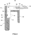
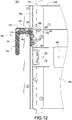
- Fig. 4 is a cross-sectional view according to a second embodiment of the present invention.
- the press portion 134 is preferably disposed between the securing portion 122 and the holding portion 112 or between the securing portion 122 and the grip portion 124, one end of the resilient element 180 is connected to the press portion 134, and the other end of the resilient element 180 is in contact with a recess 148 of the holding portion 112.
- the press member 130 is preferably an L-shaped structure.
- the L-shaped structure includes a pivot portion 132, the pivot portion 132 is disposed close to a bend portion 146 of the L-shaped structure, and the first fastening element 160 passes through the pivot portion 132 to fix the press member 130 to the holding portion 112.
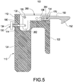
- the handle structure 100 further includes a connection member 260.
- the connection member 260 includes a first end 262 and a second end 264, the holding member 110 is connected to the first end 262, the at least one fastening hole 154 of the hook 150 is positioned corresponding to the second end 264, wherein each of the adjustment holes 136 is formed at second end 264.
- the connection member 260 is preferably an L-shaped structure which includes a pivot portion 132 disposed between the first end 262 and the second end 264. The first fastening element 160 passes through the pivot portion 132 to fix the connection member 260 to the holding portion 112.
- the resilient element 180 is preferably a compression spring.
- the press member 130 rotates about the pivot portion 132 as center, thereby directly driving the clasp portion 152 to move or indirectly driving the clasp portion 152 to move downward or upward via the connection member 260.
- the resilient element 180 resiliently pushes the press portion 134 to restore the press portion 134 to its original position, and the hook 150 also returns to its original position.
- the press member 130 or the connection member 260 includes four adjustment holes 136; the number can vary according to requirement, and the present invention is not limited to any particular number of the adjustment holes 136.
- the fastening hole 154 of the hook 150 can be fixed to a corresponding one of the adjustment holes 136 by means of the second fastening element 170, so that the clasp portion 152 protrudes from the holding member 110 by an adjustable length.
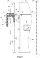
- the present invention further provides a server 200 suitable for use in a rack 210 having a plurality of retaining holes 220.
- the server 200 includes a chassis 230 and the handle structure 100 of the foregoing embodiments.
- the chassis 230 is slidably connected to the rack 210, the chassis 230 includes two slide rails 240 corresponding to each other, and the two slide rails 240 are disposed at two side surfaces 232 of the chassis 230.
- the handle structure 100 is fixed to the chassis 230 and is engaged with a corresponding one of the retaining holes 220 of the rack 210.
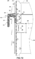
- the server 200 of the present embodiment further includes a securing plate 250; the securing plate 250 is disposed on one of the side surfaces 232 of the chassis 230, wherein the handle structure 100 is fixed to the chassis 230 by means of the securing plate 250.
- the securing plate 250 further includes a plate hole 252 corresponding to the retaining hole 220, the clasp portion 152 is inserted through and extends out of the plate hole 252 to be engaged with the retaining hole 220.
- the server 200 further includes at least one third fastening element 190, the third fastening element 190 passes through the securing plate 250 to fix the securing portion 122.
- the third fastening element 190 is a screw, a bolt, or a pin.
- the clasp portion 152 tilts upward along with the press member 130 to be separated from the retaining hole 220 of the rack 210. At this point, the user can exert a force on the grip portion 124 of the holding member 110 to pull out the chassis 230 from the rack 210. On the contrary, when the user pushes the chassis 230 back to the rack 210, an inclined surface 156 of the clasp portion 152 at one side is resiliently engaged with a corresponding retaining hole 220 to accomplish engagement with the rack 210.
- a distance between the chassis 230 and the retaining hole 220 of the rack 210 is different. Therefore, a protruding length of the clasp portion 152 has to be adjusted properly.
- the user can easily detach the second fastening element 170 to adjust the hook 150 to be fastened to an appropriate adjustment hole 136, so that the clasp portion 152 protrudes from the holding member 110 by a length longer than that in the foregoing embodiments.
- the clasp portion 152 can be engaged with a corresponding retaining hole 220 of the rack 210, so as to limit relative movement between the chassis 230 and the rack 210.
- the operation details are described in the foregoing embodiments, so the description thereof is omitted herein for brevity.
Landscapes
- Engineering & Computer Science (AREA)
- Microelectronics & Electronic Packaging (AREA)
- Computer Hardware Design (AREA)
- General Engineering & Computer Science (AREA)
- Casings For Electric Apparatus (AREA)
- Clamps And Clips (AREA)
Claims (14)
- Structure de poignée pour serveur (100), comprenant :un élément de maintien (110) incluant une portion de maintien (112) et un espace (114) formé dans la portion de maintien (112), dans laquelle l'élément de maintien (110) inclut en outre une portion de fixation (122) et une portion de prise (124), et la portion de fixation (122) et la portion de prise (124) sont respectivement reliées à deux extrémités de la portion de maintien (112),caractérisée en ce qu'elle comprend :un élément de pression (130) incluant une portion de pression (134) et une pluralité de trous de réglage (136), la portion de pression (134) étant disposée de manière à pouvoir se déplacer dans l'espace (114), dans laquelle chacun des trous de réglage (136) est disposé sur une extrémité de l'élément de pression (130) face à la portion de pression (134), etun crochet (150) incluant une portion de fermeture (152) et au moins un trou d'attache (154), le au moins un trou d'attache (154) étant positionné de manière réglable en correspondance avec l'un quelconque des trous de réglage (136), la portion de fermeture (152) étant mobile le long du déplacement de la portion de pression (134), dans laquelle la portion de fermeture (152) fait saillie hors de l'élément de maintien (110).
- Structure de poignée pour serveur selon la revendication 1, comprenant en outre un premier élément d'attache (160), un deuxième élément d'attache (170), et un élément résilient (180), le premier élément d'attache (160) attachant l'élément de pression (130) sur l'élément de maintien (110), le deuxième élément d'attache (170) passant à travers le au moins un trou d'attache (154) devant être positionné dans un trou correspondant des trous de réglage (136), l'élément résilient (180) étant disposé entre l'élément de maintien (110) et l'élément de pression (130).
- Structure de poignée pour serveur selon la revendication 2, dans laquelle la portion de maintien (112) inclut en outre deux parois latérales opposées (116) et deux trous d'assemblage (118) formés respectivement sur les parois latérales (116), l'élément de pression (130) inclut une portion à pivot (132), la portion à pivot (132) inclut un trou de pivot (142) correspondant au trou d'assemblage (118), le premier élément d'attache (160) passe à travers le trou d'assemblage (118) et le trou de pivot (142) afin d'attacher l'élément de pression (130), et l'espace (114) est formé entre les deux parois latérales (116).
- Structure de poignée pour serveur selon la revendication 3, dans laquelle l'élément de pression (130) inclut en outre un bloc de contact (138), le bloc de contact (138) est disposé dans l'espace (114), une extrémité du bloc de contact (138) est reliée à la portion à pivot (132), et chacun des trous de réglage (136) est formé sur le bloc de contact (138).
- Structure de poignée pour serveur selon la revendication 3, dans laquelle la portion de maintien (112) inclut en outre un retrait (120), la portion à pivot (132) est reliée par pivotement au trou d'assemblage (118) de la portion de maintien (112), et le retrait (120) communique avec l'espace (114).
- Structure de poignée pour serveur selon la revendication 2, dans laquelle la portion de pression (134) est disposée entre la portion de fixation (122) et la portion de maintien (112), une extrémité de l'élément résilient (180) est reliée à la portion de pression (134), et l'autre extrémité de l'élément résilient (180) est en contact avec un retrait (148) de la portion de maintien (112).
- Structure de poignée pour serveur selon la revendication 6, dans laquelle l'élément de pression (130) est une structure en forme de L, la structure en forme de L inclut une portion à pivot (132), la portion à pivot (132) est disposée à proximité d'une portion fléchie (146) de la structure en forme de L, et le premier élément d'attache (160) passe à travers la portion à pivot (132) afin de fixer l'élément de pression (130) sur la portion de maintien (112).
- Structure de poignée pour serveur selon la revendication 2, comprenant en outre un élément de liaison (260), l'élément de liaison (260) incluant une première extrémité (262) et une seconde extrémité (264), l'élément de maintien (110) étant relié à la première extrémité (262), le au moins un trou d'attache (154) du crochet (150) étant positionné en correspondance avec la seconde extrémité (264), dans laquelle chacun des trous de réglage (136) est formé sur la seconde extrémité (264).
- Structure de poignée pour serveur selon la revendication 8, dans laquelle l'élément de liaison (260) est une structure en forme de L, la structure en forme en L inclut une portion à pivot (132) disposée entre la première extrémité (262) et la seconde extrémité (264), et le premier élément d'attache (160) passe à travers la portion à pivot (132) afin de fixer l'élément de liaison (260) sur la portion de maintien (112).
- Serveur (200), convenant pour une utilisation dans un bâti (210) présentant une pluralité de trous de retenue (220), comprenant :un châssis (230) relié d'une manière permettant le coulissement au bâti (210), le châssis (230) incluant deux glissières (240) correspondant l'une avec l'autre, les deux glissières (240) étant respectivement disposées sur deux surfaces latérales (232) du châssis (230), etla structure de poignée (100) selon l'une quelconque des revendication 1 à 10, la structure de poignée (100) étant fixée sur le châssis (230) et en prise avec un trou correspondant parmi les trous de retenue (220).
- Serveur selon la revendication 10, comprenant en outre une plaque de fixation (250), la plaque de fixation (250) étant disposée sur l'une des surfaces latérales (232) du châssis (230), dans lequel la structure de poignée (100) est fixée sur le châssis (230) au moyen de la plaque de fixation (250).
- Serveur selon la revendication 10, dans lequel la plaque de fixation (250) inclut en outre un trou de plaque (252) correspondant au trou de retenue (220), la portion de fermeture (152) est introduite à travers le trou de plaque (252), et s'étend hors de celui-ci.
- Serveur selon la revendication 10, comprenant en outre au moins un troisième élément d'attache (190), et le au moins un troisième élément d'attache (190) passe à travers la plaque de fixation (250) afin de fixer la portion de fixation (122).
- Serveur selon la revendication 10, dans lequel le crochet (150) est en prise en correspondance avec le trou de retenue (220) afin de limiter le déplacement relatif entre le châssis (230) et le bâti (210).
Applications Claiming Priority (1)
| Application Number | Priority Date | Filing Date | Title |
|---|---|---|---|
| TW104214685U TWM516291U (zh) | 2015-09-10 | 2015-09-10 | 把手結構及使用該把手結構的伺服器 |
Publications (3)
| Publication Number | Publication Date |
|---|---|
| EP3148305A2 EP3148305A2 (fr) | 2017-03-29 |
| EP3148305A3 EP3148305A3 (fr) | 2017-04-19 |
| EP3148305B1 true EP3148305B1 (fr) | 2018-12-05 |
Family
ID=55640248
Family Applications (1)
| Application Number | Title | Priority Date | Filing Date |
|---|---|---|---|
| EP16187616.4A Active EP3148305B1 (fr) | 2015-09-10 | 2016-09-07 | Structure de paris et serveur l'utilisant |
Country Status (4)
| Country | Link |
|---|---|
| US (1) | US9795052B2 (fr) |
| EP (1) | EP3148305B1 (fr) |
| CN (1) | CN205158232U (fr) |
| TW (1) | TWM516291U (fr) |
Families Citing this family (36)
| Publication number | Priority date | Publication date | Assignee | Title |
|---|---|---|---|---|
| US9410348B1 (en) * | 2014-01-04 | 2016-08-09 | Carlson Pet Products, Inc. | Latch apparatus |
| TWM524045U (zh) * | 2016-02-19 | 2016-06-11 | Fivetech Technology Inc | 活動把手 |
| TWI625090B (zh) * | 2016-05-30 | 2018-05-21 | 仁寶電腦工業股份有限公司 | 機箱結構 |
| US10383250B1 (en) | 2016-09-06 | 2019-08-13 | Amazon Technologies, Inc. | Rack-mountable shippable network-attached data transfer device |
| US10051758B2 (en) * | 2016-09-08 | 2018-08-14 | Oracle International Corporation | Chassis with low-cost, tool-less fastening mechanisms for rack mount systems |
| US10058006B2 (en) * | 2016-12-07 | 2018-08-21 | Dell Products L.P. | Lever release mechanism for information handling system chassis sled |
| CN206640916U (zh) * | 2017-02-09 | 2017-11-14 | 索斯科公司 | 计算机机架系统和机架附接装置 |
| US10264698B2 (en) * | 2017-08-25 | 2019-04-16 | Facebook, Inc. | Systems and methods for mounting assembly pull-handles |
| US10687435B2 (en) | 2017-08-28 | 2020-06-16 | Facebook, Inc. | Apparatus, system, and method for enabling multiple storage-system configurations |
| US10349554B2 (en) | 2017-08-29 | 2019-07-09 | Facebook, Inc. | Apparatus, system, and method for directing air in a storage-system chassis |
| US10736228B2 (en) | 2017-08-31 | 2020-08-04 | Facebook, Inc. | Removeable drive-plane apparatus, system, and method |
| US10372360B2 (en) | 2017-09-01 | 2019-08-06 | Facebook, Inc. | Apparatus, system, and method for reconfigurable media-agnostic storage |
| US10537035B2 (en) | 2017-09-06 | 2020-01-14 | Facebook, Inc. | Apparatus, system, and method for securing hard drives in a storage chassis |
| US10429911B2 (en) | 2017-09-07 | 2019-10-01 | Facebook, Inc. | Apparatus, system, and method for detecting device types of storage devices |
| US10558248B2 (en) | 2017-09-09 | 2020-02-11 | Facebook, Inc. | Apparatus, system, and method for indicating the status of and securing hard drives |
| US10588238B2 (en) | 2017-09-18 | 2020-03-10 | Facebook, Inc. | Apparatus, system, and method for partitioning a storage-system chassis |
| US10240615B1 (en) | 2017-09-23 | 2019-03-26 | Facebook, Inc. | Apparatus, system, and method for dampening vibrations generated by exhaust fans |
| US10178791B1 (en) | 2017-09-23 | 2019-01-08 | Facebook, Inc. | Apparatus, system, and method for securing computing components to printed circuit boards |
| US10757831B2 (en) | 2017-09-26 | 2020-08-25 | Facebook, Inc. | Apparatus, system, and method for reconfiguring air flow through a chassis |
| US11549284B2 (en) * | 2018-05-16 | 2023-01-10 | Getac Technology Corporation | Locking structure |
| CN208523095U (zh) * | 2018-06-12 | 2019-02-19 | 智邦科技股份有限公司 | 一种把手、可拔插式模块以及电子设备 |
| CN109322885B (zh) * | 2018-11-05 | 2024-04-02 | 深德彩科技(深圳)股份有限公司 | 一种卡锁机构及led显示器 |
| CN113423916A (zh) * | 2018-12-20 | 2021-09-21 | 坎里格机器人技术有限公司 | 具有增强的耐腐蚀性的符合ex认证的机器人系统 |
| CN109951986B (zh) * | 2019-03-27 | 2021-06-29 | 苏州浪潮智能科技有限公司 | 一种服务器 |
| US10834842B1 (en) * | 2019-06-21 | 2020-11-10 | International Business Machines Corporation | Rack-mountable assembly with spring-hinged mounting bracket(s) |
| TWI709465B (zh) * | 2019-11-19 | 2020-11-11 | 和碩聯合科技股份有限公司 | 手把延伸結構及電子裝置機殼 |
| US11169581B1 (en) * | 2020-05-28 | 2021-11-09 | EMC IP Holding Company LLC | Cover interlock mechanism |
| TWI732590B (zh) | 2020-06-10 | 2021-07-01 | 和碩聯合科技股份有限公司 | 快拆裝置 |
| CN216412032U (zh) * | 2021-09-03 | 2022-04-29 | 富联精密电子(天津)有限公司 | 挂耳组件以及终端设备 |
| US12326167B2 (en) * | 2022-09-02 | 2025-06-10 | Hanwit Precision Industries Ltd. | Chassis quick release device |
| TWI840938B (zh) * | 2022-09-02 | 2024-05-01 | 恒昌行精密工業有限公司 | 機箱快拆裝置 |
| CN115929751B (zh) * | 2022-09-30 | 2025-03-25 | 苏州浪潮智能科技有限公司 | 一种机箱锁及机箱 |
| US12408288B2 (en) * | 2023-10-18 | 2025-09-02 | Hewlett Packard Enterprise Development Lp | Riser cage half turn fastener |
| US12376246B2 (en) * | 2023-10-27 | 2025-07-29 | Dell Products L.P. | Latch assemblies for data processing systems |
| US12408285B2 (en) | 2023-10-27 | 2025-09-02 | Dell Products L.P. | Latch assemblies for protecting chassis |
| CN117697369B (zh) * | 2024-02-02 | 2024-04-23 | 深圳市德富莱智能科技股份有限公司 | 一种自动化解锁系统 |
Family Cites Families (19)
| Publication number | Priority date | Publication date | Assignee | Title |
|---|---|---|---|---|
| CH611480A5 (en) * | 1977-03-29 | 1979-05-31 | Hasler Ag | Detachable locking device on a plug-in electronic assembly |
| US6185106B1 (en) * | 1995-12-20 | 2001-02-06 | Cisco Technology, Inc. | Printed circuit board extractor tool operated latch |
| US5820175A (en) * | 1996-09-23 | 1998-10-13 | Hartwell Corporation | Self-closing latch |
| US6181549B1 (en) * | 1997-06-24 | 2001-01-30 | Dell Products, L.P. | Chassis retaining system for an electronics rack |
| US6203075B1 (en) * | 1998-05-22 | 2001-03-20 | Hardigg Industries, Inc. | Front opening container latch |
| US6547289B1 (en) * | 1999-11-17 | 2003-04-15 | C-Tech Trailer Cabinets | Quick release latch mechanism |
| US6257439B1 (en) * | 1999-12-01 | 2001-07-10 | Te Hui Hsu | Handle for a food container |
| US6398041B1 (en) * | 1999-12-03 | 2002-06-04 | Hewlett-Packard Company | Snap system for retaining slide mounted rack system into multiple racks without tools |
| CN1537347A (zh) * | 2001-06-01 | 2004-10-13 | �Ƹ��� | 具有夹紧式安装件的锁闩 |
| US7125272B1 (en) * | 2005-12-29 | 2006-10-24 | Super Micro Computer, Inc. | Modular case handle positioning device |
| US7633760B2 (en) * | 2007-05-18 | 2009-12-15 | Aten International Co., Ltd | KVM switching device, sever rack assembly and sliding mechanism thereof |
| US7944691B1 (en) * | 2009-08-24 | 2011-05-17 | Astek Corporation | Shock and vibration proof locking handle and pawl assembly |
| CN102236387A (zh) * | 2010-04-27 | 2011-11-09 | 鸿富锦精密工业(深圳)有限公司 | 机架服务器 |
| US8608261B2 (en) * | 2010-06-22 | 2013-12-17 | Quality Craft Industries Inc. | Drawer latch |
| US8727138B2 (en) * | 2011-11-04 | 2014-05-20 | International Business Machines Corporation | Toolless rail enabling simplified installation and removal |
| CN103313569A (zh) * | 2012-03-15 | 2013-09-18 | 鸿富锦精密工业(深圳)有限公司 | 支架固定模组 |
| US9585283B2 (en) * | 2012-12-27 | 2017-02-28 | Cisco Technology, Inc. | High insertion force ejector |
| US20150250312A1 (en) * | 2014-03-05 | 2015-09-10 | Advantage Pharmacy Services Llc | Pivotable Spring-Loadable Product |
| US9725933B2 (en) * | 2014-11-25 | 2017-08-08 | Super Micro Computer Inc. | Handle structure and server using the same |
-
2015
- 2015-09-10 TW TW104214685U patent/TWM516291U/zh not_active IP Right Cessation
- 2015-09-18 CN CN201520727144.7U patent/CN205158232U/zh not_active Expired - Lifetime
-
2016
- 2016-01-11 US US14/992,192 patent/US9795052B2/en active Active
- 2016-09-07 EP EP16187616.4A patent/EP3148305B1/fr active Active
Non-Patent Citations (1)
| Title |
|---|
| None * |
Also Published As
| Publication number | Publication date |
|---|---|
| EP3148305A2 (fr) | 2017-03-29 |
| TWM516291U (zh) | 2016-01-21 |
| CN205158232U (zh) | 2016-04-13 |
| EP3148305A3 (fr) | 2017-04-19 |
| US9795052B2 (en) | 2017-10-17 |
| US20170079156A1 (en) | 2017-03-16 |
Similar Documents
| Publication | Publication Date | Title |
|---|---|---|
| EP3148305B1 (fr) | Structure de paris et serveur l'utilisant | |
| TWI548331B (zh) | 可用來拆裝擴充卡模組的固定機構及其電子裝置 | |
| CN108075328B (zh) | 快速扣接结构 | |
| CN101606789B (zh) | 滑轨固定装置 | |
| US7661778B2 (en) | Fast mounting mechanism for a telescoping slide | |
| CN101470486B (zh) | 扩展卡锁固装置 | |
| US20140133080A1 (en) | Detachable electronic device and connection apparatus usable with the same | |
| US8366217B1 (en) | Installation device for slide assembly | |
| CN102890542B (zh) | 夹持装置及具有该夹持装置的外接键盘 | |
| US8640330B2 (en) | Extracting apparatus for storage device module | |
| US10111354B2 (en) | Storage carrier | |
| US8576558B2 (en) | Mounting apparatus with rotating member for retaining and buffering data storage device | |
| US9261904B2 (en) | Point of sale system | |
| US8869994B2 (en) | Server rack with lockable tray | |
| CN107436637A (zh) | 硬盘固定装置 | |
| US20140153166A1 (en) | Electronic apparatus and detachable assembly thereof | |
| US9510477B1 (en) | Server | |
| US7778017B2 (en) | Clamp-type hard disk mount | |
| US8693182B2 (en) | Fixing mechanism for storage device | |
| CN107577284A (zh) | 安装机构 | |
| US9060426B2 (en) | Securing mechanism | |
| EP2612572B1 (fr) | Dispositif d'installation d'ensemble coulissant | |
| CN102434765A (zh) | 显示器高度调节装置 | |
| US7540574B2 (en) | Mounting apparatus for data storage device | |
| CN109068524B (zh) | 一种电气配件的连接装置 |
Legal Events
| Date | Code | Title | Description |
|---|---|---|---|
| PUAI | Public reference made under article 153(3) epc to a published international application that has entered the european phase |
Free format text: ORIGINAL CODE: 0009012 |
|
| STAA | Information on the status of an ep patent application or granted ep patent |
Free format text: STATUS: THE APPLICATION HAS BEEN PUBLISHED |
|
| PUAL | Search report despatched |
Free format text: ORIGINAL CODE: 0009013 |
|
| AK | Designated contracting states |
Kind code of ref document: A2 Designated state(s): AL AT BE BG CH CY CZ DE DK EE ES FI FR GB GR HR HU IE IS IT LI LT LU LV MC MK MT NL NO PL PT RO RS SE SI SK SM TR |
|
| AX | Request for extension of the european patent |
Extension state: BA ME |
|
| AK | Designated contracting states |
Kind code of ref document: A3 Designated state(s): AL AT BE BG CH CY CZ DE DK EE ES FI FR GB GR HR HU IE IS IT LI LT LU LV MC MK MT NL NO PL PT RO RS SE SI SK SM TR |
|
| AX | Request for extension of the european patent |
Extension state: BA ME |
|
| RIC1 | Information provided on ipc code assigned before grant |
Ipc: H05K 7/14 20060101AFI20170311BHEP |
|
| STAA | Information on the status of an ep patent application or granted ep patent |
Free format text: STATUS: REQUEST FOR EXAMINATION WAS MADE |
|
| 17P | Request for examination filed |
Effective date: 20171019 |
|
| RBV | Designated contracting states (corrected) |
Designated state(s): AL AT BE BG CH CY CZ DE DK EE ES FI FR GB GR HR HU IE IS IT LI LT LU LV MC MK MT NL NO PL PT RO RS SE SI SK SM TR |
|
| REG | Reference to a national code |
Ref country code: DE Ref legal event code: R079 Ref document number: 602016007779 Country of ref document: DE Free format text: PREVIOUS MAIN CLASS: H05K0007140000 Ipc: H05K0005020000 |
|
| RIC1 | Information provided on ipc code assigned before grant |
Ipc: H05K 5/02 20060101AFI20180522BHEP Ipc: H05K 7/14 20060101ALI20180522BHEP Ipc: H05K 7/18 20060101ALI20180522BHEP |
|
| GRAP | Despatch of communication of intention to grant a patent |
Free format text: ORIGINAL CODE: EPIDOSNIGR1 |
|
| STAA | Information on the status of an ep patent application or granted ep patent |
Free format text: STATUS: GRANT OF PATENT IS INTENDED |
|
| INTG | Intention to grant announced |
Effective date: 20180704 |
|
| GRAS | Grant fee paid |
Free format text: ORIGINAL CODE: EPIDOSNIGR3 |
|
| GRAA | (expected) grant |
Free format text: ORIGINAL CODE: 0009210 |
|
| STAA | Information on the status of an ep patent application or granted ep patent |
Free format text: STATUS: THE PATENT HAS BEEN GRANTED |
|
| AK | Designated contracting states |
Kind code of ref document: B1 Designated state(s): AL AT BE BG CH CY CZ DE DK EE ES FI FR GB GR HR HU IE IS IT LI LT LU LV MC MK MT NL NO PL PT RO RS SE SI SK SM TR |
|
| REG | Reference to a national code |
Ref country code: GB Ref legal event code: FG4D |
|
| REG | Reference to a national code |
Ref country code: CH Ref legal event code: EP |
|
| REG | Reference to a national code |
Ref country code: AT Ref legal event code: REF Ref document number: 1074752 Country of ref document: AT Kind code of ref document: T Effective date: 20181215 |
|
| REG | Reference to a national code |
Ref country code: IE Ref legal event code: FG4D |
|
| REG | Reference to a national code |
Ref country code: DE Ref legal event code: R096 Ref document number: 602016007779 Country of ref document: DE |
|
| REG | Reference to a national code |
Ref country code: NL Ref legal event code: MP Effective date: 20181205 |
|
| REG | Reference to a national code |
Ref country code: AT Ref legal event code: MK05 Ref document number: 1074752 Country of ref document: AT Kind code of ref document: T Effective date: 20181205 |
|
| REG | Reference to a national code |
Ref country code: LT Ref legal event code: MG4D |
|
| PG25 | Lapsed in a contracting state [announced via postgrant information from national office to epo] |
Ref country code: ES Free format text: LAPSE BECAUSE OF FAILURE TO SUBMIT A TRANSLATION OF THE DESCRIPTION OR TO PAY THE FEE WITHIN THE PRESCRIBED TIME-LIMIT Effective date: 20181205 Ref country code: AT Free format text: LAPSE BECAUSE OF FAILURE TO SUBMIT A TRANSLATION OF THE DESCRIPTION OR TO PAY THE FEE WITHIN THE PRESCRIBED TIME-LIMIT Effective date: 20181205 Ref country code: HR Free format text: LAPSE BECAUSE OF FAILURE TO SUBMIT A TRANSLATION OF THE DESCRIPTION OR TO PAY THE FEE WITHIN THE PRESCRIBED TIME-LIMIT Effective date: 20181205 Ref country code: NO Free format text: LAPSE BECAUSE OF FAILURE TO SUBMIT A TRANSLATION OF THE DESCRIPTION OR TO PAY THE FEE WITHIN THE PRESCRIBED TIME-LIMIT Effective date: 20190305 Ref country code: BG Free format text: LAPSE BECAUSE OF FAILURE TO SUBMIT A TRANSLATION OF THE DESCRIPTION OR TO PAY THE FEE WITHIN THE PRESCRIBED TIME-LIMIT Effective date: 20190305 Ref country code: FI Free format text: LAPSE BECAUSE OF FAILURE TO SUBMIT A TRANSLATION OF THE DESCRIPTION OR TO PAY THE FEE WITHIN THE PRESCRIBED TIME-LIMIT Effective date: 20181205 Ref country code: LT Free format text: LAPSE BECAUSE OF FAILURE TO SUBMIT A TRANSLATION OF THE DESCRIPTION OR TO PAY THE FEE WITHIN THE PRESCRIBED TIME-LIMIT Effective date: 20181205 Ref country code: LV Free format text: LAPSE BECAUSE OF FAILURE TO SUBMIT A TRANSLATION OF THE DESCRIPTION OR TO PAY THE FEE WITHIN THE PRESCRIBED TIME-LIMIT Effective date: 20181205 |
|
| PG25 | Lapsed in a contracting state [announced via postgrant information from national office to epo] |
Ref country code: AL Free format text: LAPSE BECAUSE OF FAILURE TO SUBMIT A TRANSLATION OF THE DESCRIPTION OR TO PAY THE FEE WITHIN THE PRESCRIBED TIME-LIMIT Effective date: 20181205 Ref country code: SE Free format text: LAPSE BECAUSE OF FAILURE TO SUBMIT A TRANSLATION OF THE DESCRIPTION OR TO PAY THE FEE WITHIN THE PRESCRIBED TIME-LIMIT Effective date: 20181205 Ref country code: RS Free format text: LAPSE BECAUSE OF FAILURE TO SUBMIT A TRANSLATION OF THE DESCRIPTION OR TO PAY THE FEE WITHIN THE PRESCRIBED TIME-LIMIT Effective date: 20181205 Ref country code: GR Free format text: LAPSE BECAUSE OF FAILURE TO SUBMIT A TRANSLATION OF THE DESCRIPTION OR TO PAY THE FEE WITHIN THE PRESCRIBED TIME-LIMIT Effective date: 20190306 |
|
| PG25 | Lapsed in a contracting state [announced via postgrant information from national office to epo] |
Ref country code: NL Free format text: LAPSE BECAUSE OF FAILURE TO SUBMIT A TRANSLATION OF THE DESCRIPTION OR TO PAY THE FEE WITHIN THE PRESCRIBED TIME-LIMIT Effective date: 20181205 |
|
| PG25 | Lapsed in a contracting state [announced via postgrant information from national office to epo] |
Ref country code: PT Free format text: LAPSE BECAUSE OF FAILURE TO SUBMIT A TRANSLATION OF THE DESCRIPTION OR TO PAY THE FEE WITHIN THE PRESCRIBED TIME-LIMIT Effective date: 20190405 Ref country code: CZ Free format text: LAPSE BECAUSE OF FAILURE TO SUBMIT A TRANSLATION OF THE DESCRIPTION OR TO PAY THE FEE WITHIN THE PRESCRIBED TIME-LIMIT Effective date: 20181205 Ref country code: PL Free format text: LAPSE BECAUSE OF FAILURE TO SUBMIT A TRANSLATION OF THE DESCRIPTION OR TO PAY THE FEE WITHIN THE PRESCRIBED TIME-LIMIT Effective date: 20181205 Ref country code: IT Free format text: LAPSE BECAUSE OF FAILURE TO SUBMIT A TRANSLATION OF THE DESCRIPTION OR TO PAY THE FEE WITHIN THE PRESCRIBED TIME-LIMIT Effective date: 20181205 |
|
| PG25 | Lapsed in a contracting state [announced via postgrant information from national office to epo] |
Ref country code: EE Free format text: LAPSE BECAUSE OF FAILURE TO SUBMIT A TRANSLATION OF THE DESCRIPTION OR TO PAY THE FEE WITHIN THE PRESCRIBED TIME-LIMIT Effective date: 20181205 Ref country code: SM Free format text: LAPSE BECAUSE OF FAILURE TO SUBMIT A TRANSLATION OF THE DESCRIPTION OR TO PAY THE FEE WITHIN THE PRESCRIBED TIME-LIMIT Effective date: 20181205 Ref country code: RO Free format text: LAPSE BECAUSE OF FAILURE TO SUBMIT A TRANSLATION OF THE DESCRIPTION OR TO PAY THE FEE WITHIN THE PRESCRIBED TIME-LIMIT Effective date: 20181205 Ref country code: IS Free format text: LAPSE BECAUSE OF FAILURE TO SUBMIT A TRANSLATION OF THE DESCRIPTION OR TO PAY THE FEE WITHIN THE PRESCRIBED TIME-LIMIT Effective date: 20190405 Ref country code: SK Free format text: LAPSE BECAUSE OF FAILURE TO SUBMIT A TRANSLATION OF THE DESCRIPTION OR TO PAY THE FEE WITHIN THE PRESCRIBED TIME-LIMIT Effective date: 20181205 |
|
| REG | Reference to a national code |
Ref country code: DE Ref legal event code: R097 Ref document number: 602016007779 Country of ref document: DE |
|
| PLBE | No opposition filed within time limit |
Free format text: ORIGINAL CODE: 0009261 |
|
| STAA | Information on the status of an ep patent application or granted ep patent |
Free format text: STATUS: NO OPPOSITION FILED WITHIN TIME LIMIT |
|
| PG25 | Lapsed in a contracting state [announced via postgrant information from national office to epo] |
Ref country code: DK Free format text: LAPSE BECAUSE OF FAILURE TO SUBMIT A TRANSLATION OF THE DESCRIPTION OR TO PAY THE FEE WITHIN THE PRESCRIBED TIME-LIMIT Effective date: 20181205 Ref country code: SI Free format text: LAPSE BECAUSE OF FAILURE TO SUBMIT A TRANSLATION OF THE DESCRIPTION OR TO PAY THE FEE WITHIN THE PRESCRIBED TIME-LIMIT Effective date: 20181205 |
|
| 26N | No opposition filed |
Effective date: 20190906 |
|
| PG25 | Lapsed in a contracting state [announced via postgrant information from national office to epo] |
Ref country code: TR Free format text: LAPSE BECAUSE OF FAILURE TO SUBMIT A TRANSLATION OF THE DESCRIPTION OR TO PAY THE FEE WITHIN THE PRESCRIBED TIME-LIMIT Effective date: 20181205 |
|
| PG25 | Lapsed in a contracting state [announced via postgrant information from national office to epo] |
Ref country code: MC Free format text: LAPSE BECAUSE OF FAILURE TO SUBMIT A TRANSLATION OF THE DESCRIPTION OR TO PAY THE FEE WITHIN THE PRESCRIBED TIME-LIMIT Effective date: 20181205 |
|
| REG | Reference to a national code |
Ref country code: CH Ref legal event code: PL |
|
| PG25 | Lapsed in a contracting state [announced via postgrant information from national office to epo] |
Ref country code: LI Free format text: LAPSE BECAUSE OF NON-PAYMENT OF DUE FEES Effective date: 20190930 Ref country code: CH Free format text: LAPSE BECAUSE OF NON-PAYMENT OF DUE FEES Effective date: 20190930 Ref country code: IE Free format text: LAPSE BECAUSE OF NON-PAYMENT OF DUE FEES Effective date: 20190907 Ref country code: LU Free format text: LAPSE BECAUSE OF NON-PAYMENT OF DUE FEES Effective date: 20190907 |
|
| REG | Reference to a national code |
Ref country code: BE Ref legal event code: MM Effective date: 20190930 |
|
| PG25 | Lapsed in a contracting state [announced via postgrant information from national office to epo] |
Ref country code: BE Free format text: LAPSE BECAUSE OF NON-PAYMENT OF DUE FEES Effective date: 20190930 |
|
| PG25 | Lapsed in a contracting state [announced via postgrant information from national office to epo] |
Ref country code: CY Free format text: LAPSE BECAUSE OF FAILURE TO SUBMIT A TRANSLATION OF THE DESCRIPTION OR TO PAY THE FEE WITHIN THE PRESCRIBED TIME-LIMIT Effective date: 20181205 |
|
| PG25 | Lapsed in a contracting state [announced via postgrant information from national office to epo] |
Ref country code: MT Free format text: LAPSE BECAUSE OF FAILURE TO SUBMIT A TRANSLATION OF THE DESCRIPTION OR TO PAY THE FEE WITHIN THE PRESCRIBED TIME-LIMIT Effective date: 20181205 Ref country code: HU Free format text: LAPSE BECAUSE OF FAILURE TO SUBMIT A TRANSLATION OF THE DESCRIPTION OR TO PAY THE FEE WITHIN THE PRESCRIBED TIME-LIMIT; INVALID AB INITIO Effective date: 20160907 |
|
| PG25 | Lapsed in a contracting state [announced via postgrant information from national office to epo] |
Ref country code: MK Free format text: LAPSE BECAUSE OF FAILURE TO SUBMIT A TRANSLATION OF THE DESCRIPTION OR TO PAY THE FEE WITHIN THE PRESCRIBED TIME-LIMIT Effective date: 20181205 |
|
| PGFP | Annual fee paid to national office [announced via postgrant information from national office to epo] |
Ref country code: DE Payment date: 20250930 Year of fee payment: 10 |
|
| PGFP | Annual fee paid to national office [announced via postgrant information from national office to epo] |
Ref country code: GB Payment date: 20250804 Year of fee payment: 10 |
|
| PGFP | Annual fee paid to national office [announced via postgrant information from national office to epo] |
Ref country code: FR Payment date: 20250807 Year of fee payment: 10 |