EP3148304A2 - Slide rail assembly and bracket device thereof - Google Patents
Slide rail assembly and bracket device thereof Download PDFInfo
- Publication number
- EP3148304A2 EP3148304A2 EP15203079.7A EP15203079A EP3148304A2 EP 3148304 A2 EP3148304 A2 EP 3148304A2 EP 15203079 A EP15203079 A EP 15203079A EP 3148304 A2 EP3148304 A2 EP 3148304A2
- Authority
- EP
- European Patent Office
- Prior art keywords
- bracket
- hook
- locking element
- slide rail
- rail assembly
- Prior art date
- Legal status (The legal status is an assumption and is not a legal conclusion. Google has not performed a legal analysis and makes no representation as to the accuracy of the status listed.)
- Granted
Links
- 238000010586 diagram Methods 0.000 description 19
- 230000000903 blocking effect Effects 0.000 description 4
- ORQBXQOJMQIAOY-UHFFFAOYSA-N nobelium Chemical compound [No] ORQBXQOJMQIAOY-UHFFFAOYSA-N 0.000 description 3
- 238000005452 bending Methods 0.000 description 2
- 230000001419 dependent effect Effects 0.000 description 1
- 238000011161 development Methods 0.000 description 1
- 230000018109 developmental process Effects 0.000 description 1
- 238000000034 method Methods 0.000 description 1
Images


Classifications
-
- H—ELECTRICITY
- H05—ELECTRIC TECHNIQUES NOT OTHERWISE PROVIDED FOR
- H05K—PRINTED CIRCUITS; CASINGS OR CONSTRUCTIONAL DETAILS OF ELECTRIC APPARATUS; MANUFACTURE OF ASSEMBLAGES OF ELECTRICAL COMPONENTS
- H05K7/00—Constructional details common to different types of electric apparatus
- H05K7/14—Mounting supporting structure in casing or on frame or rack
- H05K7/1485—Servers; Data center rooms, e.g. 19-inch computer racks
- H05K7/1488—Cabinets therefor, e.g. chassis or racks or mechanical interfaces between blades and support structures
- H05K7/1489—Cabinets therefor, e.g. chassis or racks or mechanical interfaces between blades and support structures characterized by the mounting of blades therein, e.g. brackets, rails, trays
-
- A—HUMAN NECESSITIES
- A47—FURNITURE; DOMESTIC ARTICLES OR APPLIANCES; COFFEE MILLS; SPICE MILLS; SUCTION CLEANERS IN GENERAL
- A47B—TABLES; DESKS; OFFICE FURNITURE; CABINETS; DRAWERS; GENERAL DETAILS OF FURNITURE
- A47B88/00—Drawers for tables, cabinets or like furniture; Guides for drawers
- A47B88/40—Sliding drawers; Slides or guides therefor
- A47B88/423—Fastening devices for slides or guides
Definitions
- the present invention is related to a slide rail assembly.
- China patent publication number CN102695396B discloses a slide rail tool free mounting frame for a server, which comprises a pair of frame positioning columns (4) arranged on a slide rail back mounting frame (1) and a frame floating hook (2).
- the frame floating hook (2) includes a pair of hooks (230) respectively arranged on a pair of wings (205), which are respectively provided with slide guide sleeves (201) and are in fixed connection through an 'arch door' shaped bending piece (206).
- the slide rail back mounting frame (1) is fixed with two slide guide columns (101), which are sleeved in the slide guide sleeves (201) and are in fixed connection through limit screws (7).
- First return springs (6) are arranged on the slide guide sleeves (201) between the wings (205) and the limit screws (7).
- the slide rail back mounting frame (1) is further provided with a floating pin hole (104) for placing a floating pin (3).
- One end of the floating pin (3) is connected to the 'arch door' shaped bending piece (206) through the limit screws (7), and the other end of the floating pin is a conical head (301) arranged in the floating pin hole (104).
- Second return springs (5) are arranged on the floating pin (3) between an end face of the conical head (301) and the limit screws (7).
- the prior art can lock or release the slide rail back mounting frame (1) through the floating pin (3) driven by an outer rail of the slide rail covered by a back frame.
- the design of the prior art is easily limited by length of the outer rail and adjustment amount of a bracket cooperating with the outer rail, such that there are restrictions on use.
- the length of the outer rail must be long enough for driving the floating pin (3) in order to lock or release the slide rail back mounting frame (1).
- the present invention aims at providing a side rail assembly capable of being easily detached from or mounted to a post of a rack.
- the slide rail assembly is configured to be mounted to a first post and a second post.
- the slide rail assembly comprises a rail element, a first bracket, and a bracket device.
- the first bracket is connected to the rail element and configured to be detachably mounted to the first post.
- the bracket device is connected to the rail element and configured to be detachably mounted to the second post.
- the bracket device comprises a second bracket, a hook connected to the second bracket and having a first leg, and a locking element operatively engaged with the second bracket.
- the locking element has a supporting feature for abutting against the first leg of the hook in order to drive the hook to stay at a close position relative to the second post.
- the claimed slide rail assembly comprises a rail element and a bracket device connected to the rail element.
- the bracket device comprises a bracket, a hook connected to the bracket and having a first leg, and a locking element operatively engaged with the bracket.
- the locking element has a supporting feature for abutting against the first leg of the hook in order to hold the hook to at a close position relative to the bracket.
- the claimed bracket device comprises a bracket, a hook, a locking element, and an extension element.
- the bracket has a first engagement part.
- the hook is connected to the bracket and located at a close position relative to the bracket.
- the locking element is operatively engaged with the first engagement part of the bracket for abutting against the hook to hold the hook at the close position.
- the extension element is connected to the locking element.
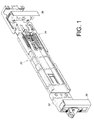
- FIG. 1 is a diagram showing a slide rail assembly 30 mounted to a first post 36 and a second post 38 by a first bracket 32 and a bracket device 34 according to an embodiment of the present invention.
- the slide rail assembly 30 comprises a rail element 40 and a supporting frame 42.
- the rail element 40 has a first end 44a and a second end 44b opposite to the first end 44a.
- the supporting frame 42 is fixed to the rail element 40 as a part of the rail element 40.
- the supporting frame 42 has an upper wall 46a, a lower wall 46b, and a longitudinal wall 48 connected between the upper wall 46a and the lower wall 46b.
- a passage 50 is defined by the upper wall 46a, the lower wall 46b and the longitudinal wall 48.
- the longitudinal wall 48 has a first part 52 (such as a bump).
- the first bracket 32 is connected to the rail element 40 to be adjacent to the first end 44a.
- the slide rail assembly 30 further comprises an extension element 54 connected to the bracket device 34.
- the extension element 54 is movably connected to the supporting frame 42 of the rail element 40 and capable of moving along the passage 50 of the supporting frame 42.
- the extension element 54 has a second part 56 correspondingly faces toward the first part 52 of the supporting frame 42.
- the bracket device 34 is located adjacent to the second end 44b of the rail element 40.
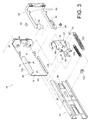
- the bracket device 34 comprises a second bracket 58, a locking element 60, and a hook 62.
- the second bracket 58 comprises a side plate 64, an end plate 66 substantially perpendicularly connected to the side plate 64, and at least one mounting element 68 mounted to the end plate 66.
- the side plate 64 has at least one first engagement part 70, a first wall 72a, and a second wall 72b.
- a space 74 is defined by the first wall 72a and the second wall 72b.
- the locking element 60 is operatively engaged with the second bracket 58.
- the locking element 60 has a first guiding part 76, such as an elongated hole, and a connection element 78 passing through part of the first guiding part 76 for connecting the locking element 60 to the side plate 64 of the second bracket 58, in order to allow the locking element 60 to move relative to the second bracket 58 within a guiding area defined by the first guiding part 76.
- the locking element 60 comprises at least one second engagement part 80, an elastic arm 81 connected to the at least one second engagement part 80, a disengagement feature 82 connected to the elastic arm 81, and at least one supporting feature 84.
- the hook 62 is connected to the second bracket 58.
- the hook 62 is movably connected to the second bracket 58 by a pivoting element 88.
- the hook 62 has at least one blocking part 90, a first leg 92 and a second leg 94.
- one of contact surfaces between the supporting feature 84 of the locking element 60 and the second leg 94 of the hook 62 is a first inclined surface 86a; and one of contact surfaces between the supporting feature 84 of the locking element 60 and the first leg 92 of the hook 62 is a second inclined surface 86b.
- the first inclined surface 86a and the second inclined surface 86b are respectively arranged at two sides of the supporting feature 84 for example.
- FIG. 4 is a diagram showing the slide rail assembly 30 mounted between the first post 36 and the second post 38 by the first bracket 32 and the bracket device 34.
- the extension element 54 is connected to the second bracket 58 and is movable in the space 74.
- the extension element 54 has a disengagement part 96 and a second guiding part 98.
- the disengagement part 96 correspondingly faces toward the disengagement feature 82 of the locking element 60.
- one of the disengagement part 96 and the disengagement feature 82 has an inclined section.
- the disengagement part 96 has the inclined section for example.
- the second guiding part 98 can be an elongated hole, and a supporting element 100 passes through part of the second guiding part 98 for connecting the extension element 54 to the side plate 64 of the second bracket 58, in order to allow the extension element 54 to move relative to the second bracket 58 within a guiding area defined by the second guiding part 98.
- the slide rail assembly 30 further comprises an elastic element 102 and at least one auxiliary elastic element 104.
- the elastic element 102 is arranged between the locking element 60 and the supporting element 100.
- the auxiliary elastic element 104 is arranged between the locking element 60 and the extension element 54.
- FIG. 6 and FIG. 7 are diagrams further show that the bracket device 34 is mounted to a hole 106 of the second post 38 by the at least one mounting element 68.
- the supporting feature 84 of the locking element 60 is configured to abut against the first leg 92 of the hook 62, in order to hold the hook 62 at a close position L1 relative to the second post 38 or the second bracket 58, where the blocking part 90 of the hook 62 corresponds to (or face toward) the second post 38.
- the hook 62 is at the close position L1
- the second engagement part 80 of the locking element 60 and the first engagement part 70 of the second bracket 58 are mutually engaged.
- the locking element 60 is located at a first position P1 relative to the second bracket 58.
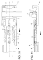
- the locking element 60 of the bracket device 34 can be operatively moved along the first direction D1 by the extension element 54, in order to drive the second bracket 58 to move, such that the blocking part 90 of the hook 62 abuts against the second post 38.
- the extension element 54 can be further operatively moved along the first direction D1, in order to allow the disengagement part 96 of the extension element 54 to abut against the disengagement feature 82 of the locking element 60. Meanwhile, the at least one auxiliary elastic element 104 is stretched due to the movement of the extension element 54 to generate an elastic force.
- the supporting feature 84 of the locking element 60 abuts against the second leg 94 of the hook 62, in order to hold the hook 62 at the open position L2. In such state, the blocking part 90 of the hook 62 no longer corresponds to the second post 38.
- the mounting element 68 of the second bracket 58 of the bracket device 34 can be separated from the hole 106 of the second post 38, in order to detach the bracket device 34 from the second post 38.
- the user can set the hook 62 in an open state, and then move the bracket device 34 toward the second post 38 along a second direction D2, such that the second bracket 58 is mounted to the hole 106 of the second post 38 by the at least one mounting element 68 with the second bracket 58 abutting against the second post 38.
- the user can apply a force to the locking element 60 along the second direction D2, in order to move the locking element 60 relative to the second bracket 58 from the second position P2 to the first position P1.
- the locking element 60 pushes the first leg 92 of the hook 62 with assistant of the second inclined surface 86b, in order to move the hook 62 relative to the second post 38 or the second bracket 58 from the open position L2 to the close position L1.
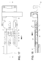
- FIG. 27 is a diagram showing a bracket device 200 according to another embodiment of the present invention.
- a locking element 202 is connected to an extension element 204. Therefore, the locking element 202 and the extension element 204 are integrated as a single component to be mounted to a bracket 206.
- one of contact surfaces between a first engagement part 208 of the bracket 206 and a second engagement part 210 of the locking element 202 is a guiding surface 212, such as an inclined surface or a curved surface.
- the guiding surface 212 of the second engagement part 210 of the locking element 202 is an inclined surface for example.
- the locking element 202 is operatively moved to a first position P1, such that the first engagement part 208 of the bracket 206 and the second engagement part 210 of the locking element 202 are mutually engaged.
- the first leg 220 of the hook 218 abuts against the supporting feature 222 of the locking element 202 for holding the hook 218 at a close position L1 relative to the post 216 or the bracket 206.
Abstract
Description
- The present invention is related to a slide rail assembly.
- China patent publication number
CN102695396B discloses a slide rail tool free mounting frame for a server, which comprises a pair of frame positioning columns (4) arranged on a slide rail back mounting frame (1) and a frame floating hook (2). The frame floating hook (2) includes a pair of hooks (230) respectively arranged on a pair of wings (205), which are respectively provided with slide guide sleeves (201) and are in fixed connection through an 'arch door' shaped bending piece (206). The slide rail back mounting frame (1) is fixed with two slide guide columns (101), which are sleeved in the slide guide sleeves (201) and are in fixed connection through limit screws (7). First return springs (6) are arranged on the slide guide sleeves (201) between the wings (205) and the limit screws (7). The slide rail back mounting frame (1) is further provided with a floating pin hole (104) for placing a floating pin (3). One end of the floating pin (3) is connected to the 'arch door' shaped bending piece (206) through the limit screws (7), and the other end of the floating pin is a conical head (301) arranged in the floating pin hole (104). Second return springs (5) are arranged on the floating pin (3) between an end face of the conical head (301) and the limit screws (7). - According to such arrangement, although the prior art can lock or release the slide rail back mounting frame (1) through the floating pin (3) driven by an outer rail of the slide rail covered by a back frame. However, the design of the prior art is easily limited by length of the outer rail and adjustment amount of a bracket cooperating with the outer rail, such that there are restrictions on use. In other words, the length of the outer rail must be long enough for driving the floating pin (3) in order to lock or release the slide rail back mounting frame (1).
- This in mind, the present invention aims at providing a side rail assembly capable of being easily detached from or mounted to a post of a rack.
- This is achieved by a side rail assembly according to
claims - As will be seen more clearly from the detailed description following below, the claimed slide rail assembly is configured to be mounted to a first post and a second post. The slide rail assembly comprises a rail element, a first bracket, and a bracket device. The first bracket is connected to the rail element and configured to be detachably mounted to the first post. The bracket device is connected to the rail element and configured to be detachably mounted to the second post. The bracket device comprises a second bracket, a hook connected to the second bracket and having a first leg, and a locking element operatively engaged with the second bracket. The locking element has a supporting feature for abutting against the first leg of the hook in order to drive the hook to stay at a close position relative to the second post. Wherein, when the first bracket is detached from the first post, and the locking element is operatively disengaged from the second bracket, the supporting feature of the locking element no longer abuts against the hook, and the hook is no longer held at the close position relative to the second post.
- As will be seen more clearly from the detailed description following below, the claimed slide rail assembly comprises a rail element and a bracket device connected to the rail element. The bracket device comprises a bracket, a hook connected to the bracket and having a first leg, and a locking element operatively engaged with the bracket. The locking element has a supporting feature for abutting against the first leg of the hook in order to hold the hook to at a close position relative to the bracket. Wherein, when the locking element is operatively disengaged from the second bracket, the supporting feature of the locking element no longer abuts against the hook, and the hook is no longer held at the close position relative to the bracket.
- As will be seen more clearly from the detailed description following below, the claimed bracket device comprises a bracket, a hook, a locking element, and an extension element. The bracket has a first engagement part. The hook is connected to the bracket and located at a close position relative to the bracket. The locking element is operatively engaged with the first engagement part of the bracket for abutting against the hook to hold the hook at the close position. The extension element is connected to the locking element. Wherein, when the locking element is operatively disengaged from the bracket, the locking element no longer abuts against the hook, and the hook is no longer held at the close position relative to the bracket.
- In the following, the invention is further illustrated by way of example, taking reference to the accompanying drawings thereof:
-
FIG. 1 is a diagram showing a slide rail assembly being mounted to a first post and a second post according to an embodiment of the present invention; -
FIG. 2 is an exploded view of the slide rail assembly according to an embodiment of the present invention; -
FIG. 3 is an exploded view of a bracket device according to an embodiment of the present invention; -
FIG. 4 is a diagram showing the slide rail assembly being mounted to the first post and the second post according to an embodiment of the present invention; -
FIG. 5 is a diagram showing the bracket device being mounted to the second post according to an embodiment of the present invention; -
FIG. 6 is a cross-sectional view along line 6-6 inFIG. 5 ; -
FIG. 7 is a cross-sectional view along line 7-7 inFIG. 5 ; -
FIG. 8 is a diagram showing a first bracket being detached from the first post; -
FIG. 9 is a diagram showing a first part of a rail element abutting against a second part of an extension element; -
FIG. 10 is a diagram showing the bracket device being moved relative to the second post along a first direction according to an embodiment of the present invention; -
FIG. 11 is a cross-sectional view along line 11-11 inFIG. 10 ; -
FIG. 12 is a diagram showing the bracket device continuing to move relative to the second post along the first direction according to an embodiment of the present invention; -
FIG. 13 is a cross-sectional view along line 13-13 inFIG. 12 ; -
FIG. 14 is a diagram showing the bracket device continuing to move relative to the second post along the first direction and a disengagement part of the extension element abutting against a disengagement feature of a locking element for disengagement according to an embodiment of the present invention; -
FIG. 15 is a cross-sectional view along line 15-15 inFIG. 14 ; -
FIG. 16 is a cross-sectional view along line 16-16 inFIG. 14 ; -
FIG. 17 is a diagram showing the locking element of the bracket device moving along the first direction in response to an elastic force of an auxiliary elastic element according to an embodiment of the present invention; -
FIG. 18 is a cross-sectional view along line 18-18 inFIG. 17 ; -
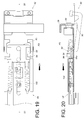
FIG. 19 is a diagram showing the locking element moving to drive a hook according to an embodiment of the present invention; -
FIG. 20 is a cross-sectional view along line 20-20 inFIG. 19 ; -
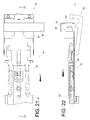
FIG. 21 is a diagram showing the bracket device being detached from the second post according to an embodiment of the present invention; -
FIG. 22 is a cross-sectional view along line 22-22 inFIG. 21 ; -
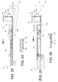
FIG. 23 is a diagram showing the bracket device being mounted to the second post along the second direction according to an embodiment of the present invention; -
FIG. 24 is a partial cross-sectional view ofFIG. 23 in another view angle for illustrating a first engagement part of a second bracket and a second engagement part of the locking element not being engaged with each other; -
FIG. 25 is a diagram showing the bracket device being mounted to the second post according to an embodiment of the present invention; -
FIG. 26 is a partial cross-sectional view ofFIG. 25 in another viewing angle for illustrating the second engagement part of the locking element and the first engagement part of the second bracket being engaged with each other; -
FIG. 27 is an exploded view of a bracket device according to another embodiment of the present invention; -
FIG. 28 is a diagram showing the bracket device being mounted to the second post along the second direction according to another embodiment of the present invention; -
FIG. 29 is a partial cross-sectional view ofFIG. 28 in another viewing angle for illustrating a first engagement part of a second bracket and a second engagement part of a locking element not being engaged with each other; -
FIG. 30 is a diagram showing the bracket device being mounted to the second post according to another embodiment of the present invention; and -
FIG. 31 is a partial cross-sectional view ofFIG. 30 in another viewing angle for illustrating the second engagement part of the locking element and the first engagement part of the second bracket being engaged with each other. -
FIG. 1 is a diagram showing aslide rail assembly 30 mounted to afirst post 36 and asecond post 38 by afirst bracket 32 and abracket device 34 according to an embodiment of the present invention. - As shown in
FIG. 2 , theslide rail assembly 30 comprises arail element 40 and a supportingframe 42. Therail element 40 has afirst end 44a and asecond end 44b opposite to thefirst end 44a. The supportingframe 42 is fixed to therail element 40 as a part of therail element 40. The supportingframe 42 has anupper wall 46a, alower wall 46b, and alongitudinal wall 48 connected between theupper wall 46a and thelower wall 46b. Apassage 50 is defined by theupper wall 46a, thelower wall 46b and thelongitudinal wall 48. Thelongitudinal wall 48 has a first part 52 (such as a bump). Thefirst bracket 32 is connected to therail element 40 to be adjacent to thefirst end 44a. Theslide rail assembly 30 further comprises anextension element 54 connected to thebracket device 34. Theextension element 54 is movably connected to the supportingframe 42 of therail element 40 and capable of moving along thepassage 50 of the supportingframe 42. Theextension element 54 has asecond part 56 correspondingly faces toward thefirst part 52 of the supportingframe 42. Thebracket device 34 is located adjacent to thesecond end 44b of therail element 40. - As shown in
FIG. 3 to FIG. 7 , thebracket device 34 comprises asecond bracket 58, a lockingelement 60, and ahook 62. Thesecond bracket 58 comprises aside plate 64, anend plate 66 substantially perpendicularly connected to theside plate 64, and at least one mountingelement 68 mounted to theend plate 66. Theside plate 64 has at least onefirst engagement part 70, afirst wall 72a, and asecond wall 72b. Aspace 74 is defined by thefirst wall 72a and thesecond wall 72b. The lockingelement 60 is operatively engaged with thesecond bracket 58. The lockingelement 60 has a first guidingpart 76, such as an elongated hole, and aconnection element 78 passing through part of the first guidingpart 76 for connecting the lockingelement 60 to theside plate 64 of thesecond bracket 58, in order to allow the lockingelement 60 to move relative to thesecond bracket 58 within a guiding area defined by the first guidingpart 76. The lockingelement 60 comprises at least onesecond engagement part 80, anelastic arm 81 connected to the at least onesecond engagement part 80, adisengagement feature 82 connected to theelastic arm 81, and at least one supportingfeature 84. Thehook 62 is connected to thesecond bracket 58. For example, thehook 62 is movably connected to thesecond bracket 58 by a pivotingelement 88. Thehook 62 has at least one blockingpart 90, afirst leg 92 and asecond leg 94. Preferably, one of contact surfaces between the supportingfeature 84 of the lockingelement 60 and thesecond leg 94 of thehook 62 is a firstinclined surface 86a; and one of contact surfaces between the supportingfeature 84 of the lockingelement 60 and thefirst leg 92 of thehook 62 is a secondinclined surface 86b. In the present embodiment, the firstinclined surface 86a and the secondinclined surface 86b are respectively arranged at two sides of the supportingfeature 84 for example. -
FIG. 4 is a diagram showing theslide rail assembly 30 mounted between thefirst post 36 and thesecond post 38 by thefirst bracket 32 and thebracket device 34. - The
extension element 54 is connected to thesecond bracket 58 and is movable in thespace 74. Theextension element 54 has adisengagement part 96 and a second guidingpart 98. Thedisengagement part 96 correspondingly faces toward thedisengagement feature 82 of the lockingelement 60. Preferably, one of thedisengagement part 96 and thedisengagement feature 82 has an inclined section. In the present embodiment, thedisengagement part 96 has the inclined section for example. Thesecond guiding part 98 can be an elongated hole, and a supportingelement 100 passes through part of the second guidingpart 98 for connecting theextension element 54 to theside plate 64 of thesecond bracket 58, in order to allow theextension element 54 to move relative to thesecond bracket 58 within a guiding area defined by the second guidingpart 98. Preferably, theslide rail assembly 30 further comprises anelastic element 102 and at least one auxiliaryelastic element 104. Theelastic element 102 is arranged between the lockingelement 60 and the supportingelement 100. The auxiliaryelastic element 104 is arranged between the lockingelement 60 and theextension element 54. -
FIG. 6 and FIG. 7 are diagrams further show that thebracket device 34 is mounted to ahole 106 of thesecond post 38 by the at least one mountingelement 68. The supportingfeature 84 of the lockingelement 60 is configured to abut against thefirst leg 92 of thehook 62, in order to hold thehook 62 at a close position L1 relative to thesecond post 38 or thesecond bracket 58, where the blockingpart 90 of thehook 62 corresponds to (or face toward) thesecond post 38. On the other hand, when thehook 62 is at the close position L1, thesecond engagement part 80 of the lockingelement 60 and thefirst engagement part 70 of thesecond bracket 58 are mutually engaged. Meanwhile, the lockingelement 60 is located at a first position P1 relative to thesecond bracket 58. - As shown in
FIG. 8 , when theslide rail assembly 30 is going to be detached from thefirst post 36 and thesecond post 38, a user can stand at a position in front of thefirst post 36 to dismount thefirst bracket 32 from the first post 36 (mounting manner is not shown in the figure) in order to separate thefirst bracket 32 from thefirst post 36. - As shown in
FIG. 9 , after thefirst bracket 32 is separated from thefirst post 36, a force can be applied to move therail element 40 along a first direction D1 until thefirst part 52 of therail element 40 abuts against thesecond part 56 of theextension element 54. Therefore, theextension element 54 can be operatively moved along the first direction D1. - As shown in
FIG. 10 and FIG. 11 , the lockingelement 60 of thebracket device 34 can be operatively moved along the first direction D1 by theextension element 54, in order to drive thesecond bracket 58 to move, such that the blockingpart 90 of thehook 62 abuts against thesecond post 38. - As shown in
FIG. 12 and FIG. 13 , theextension element 54 can be further operatively moved along the first direction D1, in order to allow thedisengagement part 96 of theextension element 54 to abut against thedisengagement feature 82 of the lockingelement 60. Meanwhile, the at least one auxiliaryelastic element 104 is stretched due to the movement of theextension element 54 to generate an elastic force. - As shown in
FIG. 14 to FIG. 16 , when thedisengagement part 96 of theextension element 54 abuts against thedisengagement feature 82 of the lockingelement 60, and theextension element 54 continues to move along the first direction D1, thedisengagement feature 82 of the lockingelement 60 is lifted up by thedisengagement part 96 of theextension element 54, such that thesecond engagement part 80 of the lockingelement 60 is disengaged from thefirst engagement part 70 of thesecond bracket 58. - As shown in
FIG. 17 and FIG. 18 , when thesecond engagement part 80 of the lockingelement 60 is disengaged from thefirst engagement part 70 of thesecond bracket 58, the lockingelement 60 is moved relative to thesecond bracket 58 along the first direction D1 from the first position P1 in response to the elastic force of theelastic element 102 and/or the auxiliaryelastic element 104, such that the supportingfeature 84 of the lockingelement 60 no longer abuts against thefirst leg 92 of thehook 62. - As shown in
FIG. 19 and FIG. 20 , while the lockingelement 60 is moved along the first direction D1 to a second position P2 by theextension element 54, since one of the contact surfaces between the supportingfeature 84 of the lockingelement 60 and thesecond leg 94 of thehook 62 is the firstinclined surface 86a, the lockingelement 60 pushes thesecond leg 94 of thehook 62 with assistant of the firstinclined surface 86a, in order to rotate thehook 62 an angle to move from the close position L1 to an open position L2 relative to thesecond post 38 or thesecond bracket 58. When the lockingelement 60 is located at the second position P2, the supportingfeature 84 of the lockingelement 60 abuts against thesecond leg 94 of thehook 62, in order to hold thehook 62 at the open position L2. In such state, the blockingpart 90 of thehook 62 no longer corresponds to thesecond post 38. - As shown in
FIG. 21 and FIG. 22 , when thehook 62 is located at the open position L2 and theextension element 54 is continuously moved along the first direction D1, the mountingelement 68 of thesecond bracket 58 of thebracket device 34 can be separated from thehole 106 of thesecond post 38, in order to detach thebracket device 34 from thesecond post 38. - As shown in
FIG. 23 and theFIG. 24 , when thebracket device 34 is going to be mounted to thesecond post 38, the user can set thehook 62 in an open state, and then move thebracket device 34 toward thesecond post 38 along a second direction D2, such that thesecond bracket 58 is mounted to thehole 106 of thesecond post 38 by the at least one mountingelement 68 with thesecond bracket 58 abutting against thesecond post 38. - As shown in
FIG. 25 and theFIG. 26 , when thesecond bracket 58 abuts against thesecond post 38, the user can apply a force to the lockingelement 60 along the second direction D2, in order to move the lockingelement 60 relative to thesecond bracket 58 from the second position P2 to the first position P1. During such process, since one of the contact surfaces between the supportingfeature 84 of the lockingelement 60 and thefirst leg 92 of thehook 62 is the second inclined surface, the lockingelement 60 pushes thefirst leg 92 of thehook 62 with assistant of the secondinclined surface 86b, in order to move thehook 62 relative to thesecond post 38 or thesecond bracket 58 from the open position L2 to the close position L1. When thehook 62 is located at the close position L1, thesecond engagement part 80 of the lockingelement 60 and thefirst engagement part 70 of thesecond bracket 58 are mutually engaged, and the supportingfeature 84 of the lockingelement 60 abuts against thefirst leg 92 of thehook 62, in order to hold thehook 62 at the close position L1 relative to thesecond post 38 or thesecond bracket 58. -
FIG. 27 is a diagram showing abracket device 200 according to another embodiment of the present invention. A lockingelement 202 is connected to anextension element 204. Therefore, the lockingelement 202 and theextension element 204 are integrated as a single component to be mounted to abracket 206. - As shown in
FIG. 28 and FIG. 29 , in another embodiment of the present invention, one of contact surfaces between afirst engagement part 208 of thebracket 206 and asecond engagement part 210 of thelocking element 202 is a guidingsurface 212, such as an inclined surface or a curved surface. In the present embodiment, the guidingsurface 212 of thesecond engagement part 210 of thelocking element 202 is an inclined surface for example. During mounting, the lockingelement 202 is located at a second position P2 relative to thebracket 206, a mountingelement 214 of thebracket 206 is mounted to apost 216 along a second direction D2, and ahook 218 is located at an open position L2 relative to thepost 216 or thebracket 206. - As shown in
FIG. 30 and FIG. 31 , the lockingelement 202 is operatively moved to a first position P1, such that thefirst engagement part 208 of thebracket 206 and thesecond engagement part 210 of thelocking element 202 are mutually engaged. Thefirst leg 220 of thehook 218 abuts against the supportingfeature 222 of thelocking element 202 for holding thehook 218 at a close position L1 relative to thepost 216 or thebracket 206. - In particular, operations for dismounting the
bracket device 200 from thepost 216 are same as the previous embodiment. The user only needs to move thelocking element 202 along a direction opposite to the second direction D2, such that thesecond engagement part 210 of thelocking element 202 can be disengaged from thefirst engagement part 208 of thebracket 206 through guiding of the guidingsurface 212. Subsequent operations are same as those in the previous embodiment. Thus no further illustration is provided.
Claims (13)
- A slide rail assembly (30), configured to be mounted to a first post (36) and a second post (38, 216), the slide rail assembly (30) comprising:a rail element (40);a first bracket (32) connected to the rail element (40) and configured to be detachably mounted to the first post (36); andcharacterized by:a bracket device (34, 200) connected to the rail element (40) and configured to be detachably mounted to the second post (38, 216), the bracket device (34, 200) comprising:a second bracket (58, 206);a hook (62, 218) connected to the second bracket (58,206), the hook (62, 218) having a first leg (92, 220); anda locking element (60, 202) operatively engaged with the second bracket (58, 206), the locking element (60, 202) having a supporting feature (84, 222) for abutting against the first leg (92, 220) of the hook (62, 218) in order to hold the hook (62, 218) at a close position relative to the second post (38, 216);wherein when the first bracket (32) is detached from the first post (36), and the locking element (60, 202) is operatively disengaged from the second bracket (58, 206), the supporting feature (84, 222) of the locking element (60, 202) no longer abuts against the first leg (92, 220) of the hook (62, 218), and the hook (62, 218) is no longer held at the close position relative to the second post (38, 216).
- The slide rail assembly of claim 1, further characterized by an extension element (54, 204) connected to the locking element (60, 202), the rail element (40) having a first part (52), the extension element (54, 204) having a second part (56) facing toward the first part (52) of the rail element (40), wherein the extension element (54, 204) is configured to be driven by the rail element (40) to move when the first part (52) abuts against the second part (56).
- The slide rail assembly of claim 2, further characterized by an auxiliary elastic element (104) arranged between the locking element (60) and the extension element (54).
- The slide rail assembly of any of claims 1-3, characterized in that the hook (62, 218) has a second leg (94), one of contact surfaces between the supporting feature (84, 222) of the locking element (60, 202) and the second leg (94) of the hook (62, 218) is an inclined surface, when the locking element (60, 202) is disengaged from the second bracket (58, 206), the inclined surface pushes the second leg (94) of the hook (62, 218) to rotate the hook (62, 218) from the close position to an open position.
- The slide rail assembly of claim 1, characterized in that the second bracket (58, 206) has a first engagement part (70, 208), the locking element has a second engagement part (80, 210) operatively engaged with the first engagement part (70, 208).
- The slide rail assembly of claim 5, characterized in that the locking element (60, 202) comprises an elastic arm (81) connected to the second engagement part (80, 210), and a disengagement feature (82) connected to the elastic arm (81), the slide rail assembly (30) further comprises an extension element (54, 204) connected to the locking element (60, 202), the extension element (54, 204) has a disengagement part (96) for disengaging the second engagement part (80, 210) of the locking element (60, 202) from the first engagement part (70, 208) of the second bracket (58, 206).
- The slide rail assembly of any of claims 1-6, characterized in that the locking element (60, 202) has a first guiding part (76), the slide rail assembly (30) further comprises a connection element (78) passing through part of the first guiding part (76) for connecting the locking element (60, 202) to the second bracket (58, 206).
- The slide rail assembly of claim 7, characterized in that the first guiding part (76) is an elongated hole.
- The slide rail assembly of claim 2, characterized in that the extension element (54, 204) has a second guiding part (98), the slide rail assembly (30) further comprises a supporting element (100) passing through part of the second guiding part (98) for connecting the extension element (54, 204) to the second bracket (58, 206).
- The slide rail assembly of claim 9, characterized in that the second guiding part (98) is an elongated hole.
- The slide rail assembly of claim 2, characterized in that the second bracket (58, 206) comprises a side plate (64), the side plate (64) has a first wall (72a) and a second wall (72b) defining a space, the extension element (54, 204) is movable in the space.
- The slide rail assembly of any of claims 1-11, characterized in that the hook (62, 218) is pivoted to the second bracket.
- A slide rail assembly (30) comprising:a rail element (40); and
characterized by:a bracket device (34, 200) connected to the rail element (40), the bracket device (34, 200) comprising:a bracket (58, 206);a hook (62, 218) connected to the bracket (58, 206), the hook (62, 218) having a first leg (92, 220); anda locking element (60, 202) operatively engaged with the bracket (58, 206), the locking element (60, 202) having a supporting feature (84, 222) for abutting against the first leg (92, 220) of the hook (62, 218) in order to hold the hook (62, 218) to at a close position relative to the bracket (58, 206);wherein when the locking element (60, 202) is operatively disengaged from the bracket (58, 206), the supporting feature (84, 222) of the locking element (60, 202) no longer abuts against the first leg (92, 220) of the hook (62, 218), and the hook (62, 218) is no longer held at the close position relative to the bracket (58, 206).14. A bracket device (34, 200) characterized by:a bracket (58, 206) having a first engagement part (70, 208) ;a hook (62, 218) connected to the bracket (58, 206) and located at a close position relative to the bracket (58, 206) ;a locking element (60, 202) operatively engaged with the first engagement part (70, 208) of the bracket (58, 206) for abutting against the hook (62, 218) to hold the hook (62, 218) at the close position; andan extension element (54, 204) connected to the locking element (60, 202);wherein when the locking element (60, 202) is operatively disengaged from the bracket (58, 206), the locking element (60, 202) no longer abuts against the hook (62, 218), and the hook (62, 218) is no longer held at the close position relative to the bracket (58, 206).15. The bracket device of claim 14, characterized in that the locking element (60, 202) has a supporting feature (84, 222), a first inclined surface and a second inclined surface are respectively arranged two sides of the supporting feature (84, 222) respectively for abutting against the hook (62, 218) at different positions relative to the locking element (60, 202).
Applications Claiming Priority (1)
| Application Number | Priority Date | Filing Date | Title |
|---|---|---|---|
| TW104131078A TWI598025B (en) | 2015-09-18 | 2015-09-18 | Slide rail assembly and bracket device thereof |
Publications (3)
| Publication Number | Publication Date |
|---|---|
| EP3148304A2 true EP3148304A2 (en) | 2017-03-29 |
| EP3148304A3 EP3148304A3 (en) | 2017-05-03 |
| EP3148304B1 EP3148304B1 (en) | 2018-12-19 |
Family
ID=55066456
Family Applications (1)
| Application Number | Title | Priority Date | Filing Date |
|---|---|---|---|
| EP15203079.7A Active EP3148304B1 (en) | 2015-09-18 | 2015-12-30 | Slide rail assembly and bracket device thereof |
Country Status (4)
| Country | Link |
|---|---|
| US (2) | US10292297B2 (en) |
| EP (1) | EP3148304B1 (en) |
| JP (1) | JP6194348B2 (en) |
| TW (1) | TWI598025B (en) |
Cited By (2)
| Publication number | Priority date | Publication date | Assignee | Title |
|---|---|---|---|---|
| CN111263559A (en) * | 2018-12-03 | 2020-06-09 | 川湖科技股份有限公司 | Sliding rail assembly |
| CN111800978A (en) * | 2019-04-09 | 2020-10-20 | 维谛技术有限公司 | Mounting upright post |
Families Citing this family (23)
| Publication number | Priority date | Publication date | Assignee | Title |
|---|---|---|---|---|
| TWI598025B (en) * | 2015-09-18 | 2017-09-01 | King Slide Works Co Ltd | Slide rail assembly and bracket device thereof |
| US20170354055A1 (en) * | 2016-06-03 | 2017-12-07 | Kunshan Lemtech SlideTechnology Co., Ltd. | Quick Release Device for a Slide Track |
| TWI600392B (en) * | 2016-07-13 | 2017-10-01 | 川湖科技股份有限公司 | Bracket device |
| TWI618505B (en) * | 2016-11-10 | 2018-03-21 | 川湖科技股份有限公司 | Slide rail with bracket device |
| TWI612921B (en) * | 2016-12-16 | 2018-02-01 | 川湖科技股份有限公司 | Slide rail mechanism |
| TWI629926B (en) * | 2017-06-20 | 2018-07-11 | 川湖科技股份有限公司 | Bracket device for coupling assembly |
| TWI637678B (en) * | 2017-08-28 | 2018-10-01 | 川湖科技股份有限公司 | Bracket device |
| TWI640277B (en) | 2017-09-15 | 2018-11-11 | 川湖科技股份有限公司 | Slide rail assembly and bracket device thereof |
| US10251299B1 (en) * | 2017-09-29 | 2019-04-02 | Dell Products, L.P. | 14G portfolio bezel lock and latching mechanism |
| CN108089654B (en) * | 2017-12-05 | 2020-05-19 | 鸿富锦精密电子(天津)有限公司 | Plug-in device and case with same |
| USD906786S1 (en) * | 2017-12-22 | 2021-01-05 | Julius Blum Gmbh | Drawer part |
| TWI649046B (en) * | 2018-03-08 | 2019-02-01 | 川湖科技股份有限公司 | Slide rail assembly and bracket device thereof |
| TWI650093B (en) * | 2018-06-01 | 2019-02-11 | 金竣企業股份有限公司 | Easy installation structure of inner rail of two-stage servo slide rail (1) |
| US10595435B2 (en) * | 2018-06-01 | 2020-03-17 | Gslide Corporation | Server rail and server rack mounting structure |
| CN110612011B (en) * | 2018-06-14 | 2020-12-04 | 金竣企业股份有限公司 | Convenient mounting structure of interior rail of two segmentation server slide rails |
| CN110612008B (en) * | 2018-06-14 | 2020-12-04 | 金竣企业股份有限公司 | Convenient mounting structure of interior rail of two segmentation server slide rails |
| TWI674857B (en) * | 2018-12-14 | 2019-10-21 | 川湖科技股份有限公司 | Bracket device |
| CN111343809B (en) * | 2018-12-19 | 2021-03-19 | 金竣企业股份有限公司 | Quick-dismantling device for slide rail and wire arranging frame |
| NL2022397B1 (en) * | 2019-01-14 | 2020-08-14 | Walraven Holding Bv J Van | Profiled section element with stepped sidewall |
| TWI689238B (en) * | 2019-02-01 | 2020-03-21 | 勤誠興業股份有限公司 | Server device and its latch mechanism |
| US10980146B1 (en) * | 2019-05-22 | 2021-04-13 | Serverlift Corporation | Rail and shelf assemblies and rack formed therewith, and methods of installing rail and shelf assemblies on a rack |
| TWI702020B (en) * | 2019-06-12 | 2020-08-21 | 川湖科技股份有限公司 | Slide rail assembly |
| CN112954938B (en) * | 2019-12-10 | 2022-08-12 | 富联精密电子(天津)有限公司 | Support assembly |
Citations (1)
| Publication number | Priority date | Publication date | Assignee | Title |
|---|---|---|---|---|
| CN102695396B (en) | 2011-03-23 | 2014-12-24 | 雅固拉国际精密工业(苏州)有限公司 | Slide rail tool free mounting frame for server |
Family Cites Families (34)
| Publication number | Priority date | Publication date | Assignee | Title |
|---|---|---|---|---|
| JP2875750B2 (en) | 1994-11-15 | 1999-03-31 | 松下電工株式会社 | Rail mounting device |
| US6681942B2 (en) | 1999-10-27 | 2004-01-27 | Hewlett-Packard Development Company | Rack mount assembly |
| US6655534B2 (en) * | 2002-01-23 | 2003-12-02 | Dell Products L.P. | Configurable rack rail system for dual mount configurations |
| US7192103B2 (en) * | 2002-07-19 | 2007-03-20 | Ergo 2000, Inc. | Spring loaded bracket assembly having a tool-less attachment and removal feature |
| TWM255624U (en) | 2003-12-30 | 2005-01-11 | King Slide Works Co Ltd | Positioning device for sliding track bracket |
| US7281694B2 (en) * | 2004-06-14 | 2007-10-16 | Hewlett-Packard Development Company, L.P. | Mounting bracket |
| US8146756B2 (en) * | 2007-04-18 | 2012-04-03 | Jonathan Manufacturing Corporation | Universal toolless rack mount bracket |
| US7703734B2 (en) * | 2007-12-27 | 2010-04-27 | King Slide Works Co., Ltd. | Slide mounting bracket structure |
| TWI361651B (en) | 2008-05-16 | 2012-04-01 | King Slide Works Co Ltd | Bracket for a slide assembly |
| CN101606789B (en) * | 2008-06-16 | 2012-05-30 | 鸿富锦精密工业(深圳)有限公司 | Sliding rail fixing device |
| CN101606790B (en) * | 2008-06-19 | 2012-05-30 | 鸿富锦精密工业(深圳)有限公司 | Slide rail fixing device |
| TWI354528B (en) * | 2008-09-01 | 2011-12-11 | King Slide Works Co Ltd | Bracket assembly |
| US8235339B2 (en) * | 2009-06-26 | 2012-08-07 | Hewlett-Packard Development Company, L.P. | Method and apparatus for engaging a rail with various support structures |
| CN102197925A (en) * | 2010-03-24 | 2011-09-28 | 鸿富锦精密工业(深圳)有限公司 | Sliding rail mounting device |
| CN102264210A (en) * | 2010-05-27 | 2011-11-30 | 鸿富锦精密工业(深圳)有限公司 | Slide rail apparatus |
| CN102548331B (en) * | 2010-12-09 | 2016-02-03 | 青岛橡胶谷知识产权有限公司 | Device for fixing slide rail |
| CN102625629B (en) * | 2011-01-28 | 2016-04-13 | 鸿富锦精密工业(深圳)有限公司 | Device for fixing slide rail |
| US8864190B2 (en) * | 2011-05-19 | 2014-10-21 | Nan Juen International Co., Ltd. | Structure of slide rail latch for cabinet |
| US8727138B2 (en) * | 2011-11-04 | 2014-05-20 | International Business Machines Corporation | Toolless rail enabling simplified installation and removal |
| US8967565B2 (en) * | 2012-09-10 | 2015-03-03 | King Slide Works Co., Ltd. | Mount bracket for slide assembly |
| CN103906402B (en) * | 2012-12-29 | 2017-11-10 | 鸿富锦精密工业(深圳)有限公司 | Device for fixing slide rail |
| US9125489B2 (en) * | 2013-06-11 | 2015-09-08 | King Slide Works Co., Ltd. | Fixing device for a slide assembly |
| US9066591B2 (en) * | 2013-06-11 | 2015-06-30 | King Slide Works Co., Ltd. | Fixing device for a slide assembly |
| US9526338B2 (en) * | 2013-09-11 | 2016-12-27 | King Slide Works Co., Ltd. | Mounting bracket for slide assembly |
| JP3187606U (en) | 2013-09-25 | 2013-12-05 | 川湖科技股▲分▼有限公司 | Bracket and slide rail assembly using the bracket |
| CN104735945B (en) | 2013-12-19 | 2017-09-05 | 鸿富锦精密电子(天津)有限公司 | Slide rail device |
| US9370120B2 (en) * | 2014-01-17 | 2016-06-14 | King Slide Works Co., Ltd. | Slide assembly |
| US9237808B2 (en) * | 2014-05-23 | 2016-01-19 | King Slide Works Co., Ltd. | Bracket assembly for slide |
| US9480183B2 (en) * | 2014-07-30 | 2016-10-25 | King Slide Works Co., Ltd. | Slide rail assembly |
| EP2979582B1 (en) * | 2014-07-31 | 2017-06-14 | King Slide Works Co., Ltd. | Slide rail assembly |
| US9681573B2 (en) * | 2014-10-07 | 2017-06-13 | King Slide Works Co., Ltd. | Slide rail assembly |
| US9328769B1 (en) * | 2015-01-27 | 2016-05-03 | King Slide Works Co., Ltd. | Slide rail assembly and bracket device thereof |
| JP3197165U (en) | 2015-02-10 | 2015-04-23 | 川湖科技股▲分▼有限公司 | Slide rail kit and bracket device thereof |
| TWI598025B (en) * | 2015-09-18 | 2017-09-01 | King Slide Works Co Ltd | Slide rail assembly and bracket device thereof |
-
2015
- 2015-09-18 TW TW104131078A patent/TWI598025B/en active
- 2015-12-01 US US14/955,055 patent/US10292297B2/en active Active
- 2015-12-24 JP JP2015251942A patent/JP6194348B2/en active Active
- 2015-12-30 EP EP15203079.7A patent/EP3148304B1/en active Active
-
2019
- 2019-03-20 US US16/359,993 patent/US10772232B2/en active Active
Patent Citations (1)
| Publication number | Priority date | Publication date | Assignee | Title |
|---|---|---|---|---|
| CN102695396B (en) | 2011-03-23 | 2014-12-24 | 雅固拉国际精密工业(苏州)有限公司 | Slide rail tool free mounting frame for server |
Cited By (3)
| Publication number | Priority date | Publication date | Assignee | Title |
|---|---|---|---|---|
| CN111263559A (en) * | 2018-12-03 | 2020-06-09 | 川湖科技股份有限公司 | Sliding rail assembly |
| CN111263559B (en) * | 2018-12-03 | 2021-04-13 | 川湖科技股份有限公司 | Sliding rail assembly |
| CN111800978A (en) * | 2019-04-09 | 2020-10-20 | 维谛技术有限公司 | Mounting upright post |
Also Published As
| Publication number | Publication date |
|---|---|
| JP6194348B2 (en) | 2017-09-06 |
| TWI598025B (en) | 2017-09-01 |
| US10772232B2 (en) | 2020-09-08 |
| TW201713195A (en) | 2017-04-01 |
| US20170079427A1 (en) | 2017-03-23 |
| US10292297B2 (en) | 2019-05-14 |
| EP3148304B1 (en) | 2018-12-19 |
| US20190223313A1 (en) | 2019-07-18 |
| JP2017059803A (en) | 2017-03-23 |
| EP3148304A3 (en) | 2017-05-03 |
Similar Documents
| Publication | Publication Date | Title |
|---|---|---|
| EP3148304A2 (en) | Slide rail assembly and bracket device thereof | |
| EP3122164B1 (en) | Slide rail assembly and bracket device thereof | |
| EP3449768B1 (en) | Bracket device | |
| US10194556B2 (en) | Slide rail mechanism and bracket device thereof | |
| EP3131375B1 (en) | Slide rail assembly and bracket device thereof | |
| EP3154321A2 (en) | Slide rail assembly with bracket | |
| EP3136830B1 (en) | Slide rail assembly and bracket thereof | |
| US10306983B2 (en) | Slide rail mechanism | |
| US10357105B2 (en) | Coupling assembly and bracket device thereof | |
| US20160262538A1 (en) | Slide rail assembly | |
| US10172458B2 (en) | Bracket device | |
| EP3041329A1 (en) | Cable management arm | |
| CN106559964B (en) | Sliding rail assembly and its bracket system | |
| EP3030065B1 (en) | Cable management arm supporting device and mounting assembly thereof | |
| US20200187646A1 (en) | Bracket device |
Legal Events
| Date | Code | Title | Description |
|---|---|---|---|
| PUAI | Public reference made under article 153(3) epc to a published international application that has entered the european phase |
Free format text: ORIGINAL CODE: 0009012 |
|
| AK | Designated contracting states |
Kind code of ref document: A2 Designated state(s): AL AT BE BG CH CY CZ DE DK EE ES FI FR GB GR HR HU IE IS IT LI LT LU LV MC MK MT NL NO PL PT RO RS SE SI SK SM TR |
|
| AX | Request for extension of the european patent |
Extension state: BA ME |
|
| PUAL | Search report despatched |
Free format text: ORIGINAL CODE: 0009013 |
|
| AK | Designated contracting states |
Kind code of ref document: A3 Designated state(s): AL AT BE BG CH CY CZ DE DK EE ES FI FR GB GR HR HU IE IS IT LI LT LU LV MC MK MT NL NO PL PT RO RS SE SI SK SM TR |
|
| AX | Request for extension of the european patent |
Extension state: BA ME |
|
| RIC1 | Information provided on ipc code assigned before grant |
Ipc: H05K 7/14 20060101AFI20170325BHEP |
|
| 17P | Request for examination filed |
Effective date: 20171030 |
|
| RBV | Designated contracting states (corrected) |
Designated state(s): AL AT BE BG CH CY CZ DE DK EE ES FI FR GB GR HR HU IE IS IT LI LT LU LV MC MK MT NL NO PL PT RO RS SE SI SK SM TR |
|
| REG | Reference to a national code |
Ref country code: DE Ref legal event code: R079 Ref document number: 602015021799 Country of ref document: DE Free format text: PREVIOUS MAIN CLASS: H05K0007140000 Ipc: A47B0088423000 |
|
| RIC1 | Information provided on ipc code assigned before grant |
Ipc: A47B 88/423 20170101AFI20180529BHEP Ipc: H05K 7/14 20060101ALI20180529BHEP |
|
| GRAP | Despatch of communication of intention to grant a patent |
Free format text: ORIGINAL CODE: EPIDOSNIGR1 |
|
| INTG | Intention to grant announced |
Effective date: 20180706 |
|
| RIN1 | Information on inventor provided before grant (corrected) |
Inventor name: YU, KAI-WEN Inventor name: YANG, SHUN-HO Inventor name: CHEN, KEN-CHING Inventor name: WANG, CHUN-CHIANG |
|
| GRAS | Grant fee paid |
Free format text: ORIGINAL CODE: EPIDOSNIGR3 |
|
| GRAA | (expected) grant |
Free format text: ORIGINAL CODE: 0009210 |
|
| AK | Designated contracting states |
Kind code of ref document: B1 Designated state(s): AL AT BE BG CH CY CZ DE DK EE ES FI FR GB GR HR HU IE IS IT LI LT LU LV MC MK MT NL NO PL PT RO RS SE SI SK SM TR |
|
| REG | Reference to a national code |
Ref country code: GB Ref legal event code: FG4D |
|
| REG | Reference to a national code |
Ref country code: CH Ref legal event code: EP |
|
| REG | Reference to a national code |
Ref country code: IE Ref legal event code: FG4D |
|
| REG | Reference to a national code |
Ref country code: DE Ref legal event code: R096 Ref document number: 602015021799 Country of ref document: DE |
|
| REG | Reference to a national code |
Ref country code: AT Ref legal event code: REF Ref document number: 1077755 Country of ref document: AT Kind code of ref document: T Effective date: 20190115 |
|
| REG | Reference to a national code |
Ref country code: NL Ref legal event code: MP Effective date: 20181219 |
|
| PG25 | Lapsed in a contracting state [announced via postgrant information from national office to epo] |
Ref country code: LV Free format text: LAPSE BECAUSE OF FAILURE TO SUBMIT A TRANSLATION OF THE DESCRIPTION OR TO PAY THE FEE WITHIN THE PRESCRIBED TIME-LIMIT Effective date: 20181219 Ref country code: HR Free format text: LAPSE BECAUSE OF FAILURE TO SUBMIT A TRANSLATION OF THE DESCRIPTION OR TO PAY THE FEE WITHIN THE PRESCRIBED TIME-LIMIT Effective date: 20181219 Ref country code: BG Free format text: LAPSE BECAUSE OF FAILURE TO SUBMIT A TRANSLATION OF THE DESCRIPTION OR TO PAY THE FEE WITHIN THE PRESCRIBED TIME-LIMIT Effective date: 20190319 Ref country code: NO Free format text: LAPSE BECAUSE OF FAILURE TO SUBMIT A TRANSLATION OF THE DESCRIPTION OR TO PAY THE FEE WITHIN THE PRESCRIBED TIME-LIMIT Effective date: 20190319 Ref country code: LT Free format text: LAPSE BECAUSE OF FAILURE TO SUBMIT A TRANSLATION OF THE DESCRIPTION OR TO PAY THE FEE WITHIN THE PRESCRIBED TIME-LIMIT Effective date: 20181219 Ref country code: FI Free format text: LAPSE BECAUSE OF FAILURE TO SUBMIT A TRANSLATION OF THE DESCRIPTION OR TO PAY THE FEE WITHIN THE PRESCRIBED TIME-LIMIT Effective date: 20181219 |
|
| REG | Reference to a national code |
Ref country code: LT Ref legal event code: MG4D |
|
| REG | Reference to a national code |
Ref country code: AT Ref legal event code: MK05 Ref document number: 1077755 Country of ref document: AT Kind code of ref document: T Effective date: 20181219 |
|
| PG25 | Lapsed in a contracting state [announced via postgrant information from national office to epo] |
Ref country code: SE Free format text: LAPSE BECAUSE OF FAILURE TO SUBMIT A TRANSLATION OF THE DESCRIPTION OR TO PAY THE FEE WITHIN THE PRESCRIBED TIME-LIMIT Effective date: 20181219 Ref country code: RS Free format text: LAPSE BECAUSE OF FAILURE TO SUBMIT A TRANSLATION OF THE DESCRIPTION OR TO PAY THE FEE WITHIN THE PRESCRIBED TIME-LIMIT Effective date: 20181219 Ref country code: AL Free format text: LAPSE BECAUSE OF FAILURE TO SUBMIT A TRANSLATION OF THE DESCRIPTION OR TO PAY THE FEE WITHIN THE PRESCRIBED TIME-LIMIT Effective date: 20181219 Ref country code: GR Free format text: LAPSE BECAUSE OF FAILURE TO SUBMIT A TRANSLATION OF THE DESCRIPTION OR TO PAY THE FEE WITHIN THE PRESCRIBED TIME-LIMIT Effective date: 20190320 |
|
| PG25 | Lapsed in a contracting state [announced via postgrant information from national office to epo] |
Ref country code: NL Free format text: LAPSE BECAUSE OF FAILURE TO SUBMIT A TRANSLATION OF THE DESCRIPTION OR TO PAY THE FEE WITHIN THE PRESCRIBED TIME-LIMIT Effective date: 20181219 |
|
| PG25 | Lapsed in a contracting state [announced via postgrant information from national office to epo] |
Ref country code: PL Free format text: LAPSE BECAUSE OF FAILURE TO SUBMIT A TRANSLATION OF THE DESCRIPTION OR TO PAY THE FEE WITHIN THE PRESCRIBED TIME-LIMIT Effective date: 20181219 Ref country code: CZ Free format text: LAPSE BECAUSE OF FAILURE TO SUBMIT A TRANSLATION OF THE DESCRIPTION OR TO PAY THE FEE WITHIN THE PRESCRIBED TIME-LIMIT Effective date: 20181219 Ref country code: IT Free format text: LAPSE BECAUSE OF FAILURE TO SUBMIT A TRANSLATION OF THE DESCRIPTION OR TO PAY THE FEE WITHIN THE PRESCRIBED TIME-LIMIT Effective date: 20181219 Ref country code: PT Free format text: LAPSE BECAUSE OF FAILURE TO SUBMIT A TRANSLATION OF THE DESCRIPTION OR TO PAY THE FEE WITHIN THE PRESCRIBED TIME-LIMIT Effective date: 20190419 Ref country code: ES Free format text: LAPSE BECAUSE OF FAILURE TO SUBMIT A TRANSLATION OF THE DESCRIPTION OR TO PAY THE FEE WITHIN THE PRESCRIBED TIME-LIMIT Effective date: 20181219 |
|
| REG | Reference to a national code |
Ref country code: CH Ref legal event code: PL |
|
| PG25 | Lapsed in a contracting state [announced via postgrant information from national office to epo] |
Ref country code: RO Free format text: LAPSE BECAUSE OF FAILURE TO SUBMIT A TRANSLATION OF THE DESCRIPTION OR TO PAY THE FEE WITHIN THE PRESCRIBED TIME-LIMIT Effective date: 20181219 Ref country code: SK Free format text: LAPSE BECAUSE OF FAILURE TO SUBMIT A TRANSLATION OF THE DESCRIPTION OR TO PAY THE FEE WITHIN THE PRESCRIBED TIME-LIMIT Effective date: 20181219 Ref country code: IS Free format text: LAPSE BECAUSE OF FAILURE TO SUBMIT A TRANSLATION OF THE DESCRIPTION OR TO PAY THE FEE WITHIN THE PRESCRIBED TIME-LIMIT Effective date: 20190419 Ref country code: EE Free format text: LAPSE BECAUSE OF FAILURE TO SUBMIT A TRANSLATION OF THE DESCRIPTION OR TO PAY THE FEE WITHIN THE PRESCRIBED TIME-LIMIT Effective date: 20181219 Ref country code: LU Free format text: LAPSE BECAUSE OF NON-PAYMENT OF DUE FEES Effective date: 20181230 Ref country code: SM Free format text: LAPSE BECAUSE OF FAILURE TO SUBMIT A TRANSLATION OF THE DESCRIPTION OR TO PAY THE FEE WITHIN THE PRESCRIBED TIME-LIMIT Effective date: 20181219 |
|
| REG | Reference to a national code |
Ref country code: DE Ref legal event code: R097 Ref document number: 602015021799 Country of ref document: DE |
|
| REG | Reference to a national code |
Ref country code: BE Ref legal event code: MM Effective date: 20181231 |
|
| PLBE | No opposition filed within time limit |
Free format text: ORIGINAL CODE: 0009261 |
|
| STAA | Information on the status of an ep patent application or granted ep patent |
Free format text: STATUS: NO OPPOSITION FILED WITHIN TIME LIMIT |
|
| PG25 | Lapsed in a contracting state [announced via postgrant information from national office to epo] |
Ref country code: AT Free format text: LAPSE BECAUSE OF FAILURE TO SUBMIT A TRANSLATION OF THE DESCRIPTION OR TO PAY THE FEE WITHIN THE PRESCRIBED TIME-LIMIT Effective date: 20181219 Ref country code: DK Free format text: LAPSE BECAUSE OF FAILURE TO SUBMIT A TRANSLATION OF THE DESCRIPTION OR TO PAY THE FEE WITHIN THE PRESCRIBED TIME-LIMIT Effective date: 20181219 Ref country code: MC Free format text: LAPSE BECAUSE OF FAILURE TO SUBMIT A TRANSLATION OF THE DESCRIPTION OR TO PAY THE FEE WITHIN THE PRESCRIBED TIME-LIMIT Effective date: 20181219 |
|
| 26N | No opposition filed |
Effective date: 20190920 |
|
| PG25 | Lapsed in a contracting state [announced via postgrant information from national office to epo] |
Ref country code: BE Free format text: LAPSE BECAUSE OF NON-PAYMENT OF DUE FEES Effective date: 20181231 |
|
| PG25 | Lapsed in a contracting state [announced via postgrant information from national office to epo] |
Ref country code: CH Free format text: LAPSE BECAUSE OF NON-PAYMENT OF DUE FEES Effective date: 20181231 Ref country code: LI Free format text: LAPSE BECAUSE OF NON-PAYMENT OF DUE FEES Effective date: 20181231 |
|
| REG | Reference to a national code |
Ref country code: DE Ref legal event code: R082 Ref document number: 602015021799 Country of ref document: DE Representative=s name: 2K PATENT- UND RECHTSANWAELTE PARTNERSCHAFT MB, DE |
|
| PG25 | Lapsed in a contracting state [announced via postgrant information from national office to epo] |
Ref country code: MT Free format text: LAPSE BECAUSE OF NON-PAYMENT OF DUE FEES Effective date: 20181230 |
|
| PG25 | Lapsed in a contracting state [announced via postgrant information from national office to epo] |
Ref country code: FR Free format text: LAPSE BECAUSE OF NON-PAYMENT OF DUE FEES Effective date: 20190219 Ref country code: SI Free format text: LAPSE BECAUSE OF FAILURE TO SUBMIT A TRANSLATION OF THE DESCRIPTION OR TO PAY THE FEE WITHIN THE PRESCRIBED TIME-LIMIT Effective date: 20181219 |
|
| PG25 | Lapsed in a contracting state [announced via postgrant information from national office to epo] |
Ref country code: TR Free format text: LAPSE BECAUSE OF FAILURE TO SUBMIT A TRANSLATION OF THE DESCRIPTION OR TO PAY THE FEE WITHIN THE PRESCRIBED TIME-LIMIT Effective date: 20181219 |
|
| PG25 | Lapsed in a contracting state [announced via postgrant information from national office to epo] |
Ref country code: CY Free format text: LAPSE BECAUSE OF FAILURE TO SUBMIT A TRANSLATION OF THE DESCRIPTION OR TO PAY THE FEE WITHIN THE PRESCRIBED TIME-LIMIT Effective date: 20181219 Ref country code: HU Free format text: LAPSE BECAUSE OF FAILURE TO SUBMIT A TRANSLATION OF THE DESCRIPTION OR TO PAY THE FEE WITHIN THE PRESCRIBED TIME-LIMIT; INVALID AB INITIO Effective date: 20151230 Ref country code: MK Free format text: LAPSE BECAUSE OF NON-PAYMENT OF DUE FEES Effective date: 20181219 |
|
| PGFP | Annual fee paid to national office [announced via postgrant information from national office to epo] |
Ref country code: GB Payment date: 20231207 Year of fee payment: 9 |
|
| PGFP | Annual fee paid to national office [announced via postgrant information from national office to epo] |
Ref country code: IE Payment date: 20231206 Year of fee payment: 9 Ref country code: DE Payment date: 20231207 Year of fee payment: 9 |