EP3148302B1 - Structure imperméable à l'eau de module radiofréquence et module radiofréquence comportant une telle structure - Google Patents
Structure imperméable à l'eau de module radiofréquence et module radiofréquence comportant une telle structure Download PDFInfo
- Publication number
- EP3148302B1 EP3148302B1 EP15815142.3A EP15815142A EP3148302B1 EP 3148302 B1 EP3148302 B1 EP 3148302B1 EP 15815142 A EP15815142 A EP 15815142A EP 3148302 B1 EP3148302 B1 EP 3148302B1
- Authority
- EP
- European Patent Office
- Prior art keywords
- sealing layer
- grooves
- jacks
- frequency module
- radio frequency
- Prior art date
- Legal status (The legal status is an assumption and is not a legal conclusion. Google has not performed a legal analysis and makes no representation as to the accuracy of the status listed.)
- Active
Links
- 238000007789 sealing Methods 0.000 claims description 171
- 230000002093 peripheral effect Effects 0.000 claims description 7
- 238000000465 moulding Methods 0.000 claims description 5
- 239000000463 material Substances 0.000 claims description 4
- 239000002184 metal Substances 0.000 claims description 3
- 238000010586 diagram Methods 0.000 description 6
- 230000008878 coupling Effects 0.000 description 2
- 238000010168 coupling process Methods 0.000 description 2
- 238000005859 coupling reaction Methods 0.000 description 2
- 230000000694 effects Effects 0.000 description 2
- 230000001681 protective effect Effects 0.000 description 2
- 238000011109 contamination Methods 0.000 description 1
- 230000001419 dependent effect Effects 0.000 description 1
- 230000007613 environmental effect Effects 0.000 description 1
- 238000000034 method Methods 0.000 description 1
- 238000004078 waterproofing Methods 0.000 description 1
Images


Classifications
-
- F—MECHANICAL ENGINEERING; LIGHTING; HEATING; WEAPONS; BLASTING
- F16—ENGINEERING ELEMENTS AND UNITS; GENERAL MEASURES FOR PRODUCING AND MAINTAINING EFFECTIVE FUNCTIONING OF MACHINES OR INSTALLATIONS; THERMAL INSULATION IN GENERAL
- F16L—PIPES; JOINTS OR FITTINGS FOR PIPES; SUPPORTS FOR PIPES, CABLES OR PROTECTIVE TUBING; MEANS FOR THERMAL INSULATION IN GENERAL
- F16L5/00—Devices for use where pipes, cables or protective tubing pass through walls or partitions
- F16L5/02—Sealing
-
- H—ELECTRICITY
- H05—ELECTRIC TECHNIQUES NOT OTHERWISE PROVIDED FOR
- H05K—PRINTED CIRCUITS; CASINGS OR CONSTRUCTIONAL DETAILS OF ELECTRIC APPARATUS; MANUFACTURE OF ASSEMBLAGES OF ELECTRICAL COMPONENTS
- H05K5/00—Casings, cabinets or drawers for electric apparatus
- H05K5/06—Hermetically-sealed casings
- H05K5/069—Other details of the casing, e.g. wall structure, passage for a connector, a cable, a shaft
Definitions
- the present invention relates to communications devices, and in particular, to a radio frequency module waterproof structure and a device.
- DE 20 2012 101 639 U1 refers to a housing for one or more cables, comprising a housing lower part, which is designed to be arranged on a housing, and a housing upper part, which is delimited by an open state, at least one cable feedthrough seal being arranged at least in the housing lower part for accommodating a housing part, the housing bottom part being arranged in a closed state in which it is fastened to the lower housing part and wherein one or more fastening means for attaching the lower housing part to an electrical subassembly in an inner space is provided.
- Radio frequency modules such as an outdoor building baseband unit BBU (Building Base band Unit) need to have very high environmental adaptability.
- BBU Building Base band Unit
- a cable of an existing radio frequency module is inserted into a rubber ring, and then the rubber ring is sealed and fastened at a module housing, to achieve waterproofing.
- this waterproof structure has low mounting efficiency, high operation space requirements, and high costs.
- An objective of the present invention is to provide a radio frequency module waterproof structure, so as to resolve technical problems of poor assembly efficiency and complex operation.
- the invention is defined by the features of claim 1. Further embodiments are defined in the dependent claims.
- the waterproof structure including a case body, a cover body, a first sealing layer, a middle sealing layer, and a second sealing layer, the first sealing layer is mounted on the case body, and the second sealing layer is mounted on the cover body and is arranged opposite to the first sealing layer; the cover body covers the case body, and the middle sealing layer is sandwiched between the first sealing layer and the second sealing layer; at least two first jacks are formed at a junction of the first sealing layer and the middle sealing layer; and at least two second jacks are formed at a junction of the second sealing layer and the middle sealing layer, and the at least two first sealed through holes and the at least two second jacks are distributed at two layers, one above the other, and are arranged in a staggered manner, wherein a support body is wrapped inside the middle sealing layer, and the support body and the middle sealing layer are formed by means of insert molding, wherein the support body is a metal piece that has a same shape as that of the middle sealing layer and a size smaller than that of the
- At least two adjacently-arranged first grooves that have arc-shaped cross sections are disposed on a surface that is of the first sealing layer and that faces the middle sealing layer, second grooves corresponding to the first grooves are disposed at the middle sealing layer, and the second grooves and the first grooves are correspondingly coupled to form the first jacks.
- At least two adjacently-arranged third grooves that have arc-shaped cross sections are disposed on a surface that is of the second sealing layer and that faces the middle sealing layer, fourth grooves corresponding to the third grooves are disposed at the middle sealing layer, and the third grooves and the fourth grooves are correspondingly coupled to form the second jacks.
- the first sealing layer includes a first mounting surface and two opposite first end surfaces connected to the first mounting surface, and the at least two first grooves are adjacently disposed on the first mounting surface, and two ends of the at least two first grooves penetrate the two first end surfaces.
- the middle sealing layer further includes two oppositely-arranged second mounting surfaces and two oppositely-arranged second end surfaces, the two second end surfaces are respectively connected to the two second mounting surfaces, and the second grooves are disposed on one of the second mounting surfaces; and the at least two third grooves are disposed on the other second mounting surface, and two ends of the second grooves and two ends of the at least two third grooves penetrate the two second end surfaces.
- first sealing layer and the middle sealing layer are connected by using a connection strip.
- first sealing layer and the middle sealing layer are connected by means of integrated molding, and the first jacks are through holes that have round cross sections and that are disposed at the junction of the first sealing layer and the middle sealing layer.
- the first sealing layer is connected to first plugs corresponding to the first jacks; and the middle sealing layer is connected to second plugs corresponding to the second jacks.
- multiple annular recessed portions are disposed in inner peripheral walls of the first and the second jacks; and protrusions opposite to the recessed portions are disposed at outer peripheral edges of the first and the second plugs.
- the second sealing layer, and the middle sealing layer are made of a rubber material.
- a radio frequency module including the radio frequency module waterproof structure according to any manner of the first aspect, where external high-density cables of the radio frequency module are inserted into the first jacks and second jacks, a cover body is fastened to the case body, the first sealing layer, the second sealing layer, and the middle sealing layer are sandwiched by the cover body and the case body, and the first sealing layer, the second sealing layer, and the middle sealing layer seal the high-density cables.
- the radio frequency module waterproof structure of the present utility model multiple separate cable jacks are disposed between the first sealing layer and a second sealing layer, and a cable can be easily inserted and connected by opening a cover body; and then the first sealing layer and the second sealing layer are tightly pressed to deform, so as to fasten and waterproof multiple cables simultaneously.
- the radio frequency module waterproof structure has a simple structure, can be operated conveniently and rapidly, and is more applicable to miniaturized modules.
- an embodiment of the present invention provides a radio frequency module waterproof structure.
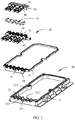
- the radio frequency module waterproof structure includes a case body 10, a cover body 20, a first sealing layer 30, a middle sealing layer 40, and a second sealing layer 50.
- the first sealing layer 30 is mounted on the case body 10, and the second sealing layer 50 is mounted on the cover body 20 and is arranged opposite to the first sealing layer 30; the cover body 20 covers the case body 10, and the middle sealing layer 40 is sandwiched between the first sealing layer 30 and the second sealing layer 50; at least two first jacks 60 are formed at a junction of the first sealing layer 30 and the middle sealing layer 40; and at least two second jacks 70 are disposed at a junction of the second sealing layer 50 and the middle sealing layer 40, and the at least two first jacks 60 and the at least two second jacks 70 are distributed at two layers, one above the other, and are arranged in a staggered manner.
- the first sealing layer 30, the second sealing layer 50, and the middle sealing layer 40 are made of a rubber material.
- the four first jacks 60 are arranged in parallel in a same plane
- the second jacks 70 are arranged in parallel in a same plane, and are parallel to the plane in which the first jacks 60 are located, and positions of the four first jacks 60 and opposite to positions between the five second jacks 70.
- the case body 10 is a radio frequency module housing, and has a front surface 11.
- a first assembly groove 12 is disposed at an edge of one end of the front surface 11.
- the first assembly groove 12 is a long-strip-shaped groove, and includes a groove bottom wall (not shown in the figure), opposite groove side walls 122 at two sides of the groove bottom wall, and groove end walls at two ends of the groove bottom wall (not shown in the figure).
- Multiple spaced clamping protrusions 124 protrude from the groove bottom wall.
- Gaps 125 corresponding to the first jacks 60 are disposed on each of the two groove side walls 122.
- the two groove end walls tilt towards the groove bottom wall.
- Multiple clamping grooves 31 are disposed on a surface that is of the first sealing layer 30 and far from the middle sealing layer 40.
- the first sealing layer 30 is accommodated in the first assembly groove 12, and the clamping protrusions 124 and the clamping grooves 31 perform clamping, so as to fasten the first sealing layer 30.
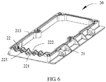
- the cover body 20 has a back surface 21.
- a second assembly groove 22 opposite to the first assembly groove 12 is disposed on the back surface 21.
- the second assembly groove 22 includes two groove side walls 221 and a groove bottom wall (not shown in the figure). Gaps 222 corresponding to the second jacks 70 are disposed on the groove side walls 221. Protrusions 223 protrude from the groove bottom wall of the second assembly groove 22.
- a groove 213 is disposed at a peripheral edge of the back surface 21. The groove 213 is connected to two ends of the second assembly groove 22, and communicates with the second assembly groove 22.
- the second sealing layer 50 is a strip-shaped block body, two opposite ends of the second sealing layer 50 tilt towards the first jacks 60, one annular sealing strip 51 corresponding to the groove 213 extends from one end wall of the second sealing layer 50, and the sealing strip 51 is connected to the other end wall.
- the second sealing layer 50 is accommodated in the second assembly groove, and the sealing strip 51 is accommodated in the groove 213.
- Multiple external cables of the radio frequency module are inserted into the first jacks 60 and the second jacks 70, and the cover body 20 is locked on the case body 10 by means of a screw and the like.
- the first sealing layer 30 and the second sealing layer 50 press the middle sealing layer 40 tightly, and therefore, each cable is waterproofed by means of a tight fit between the middle sealing layer 40 and each of the first sealing layer 30 and the second sealing layer 50.
- the radio frequency module waterproof structure of the present invention multiple separate cable jacks are disposed between a first sealing layer 30 and a second sealing layer 50, and a cable can be easily inserted and connected by opening a cover body 20; and then the first sealing layer 30 and the second sealing layer 50 are tightly pressed to deform, so as to fasten and waterproof multiple cables simultaneously.
- the radio frequency module waterproof structure has a simple structure, can be operated conveniently and rapidly, and is more applicable to miniaturized modules.
- a support body 42 is wrapped inside the middle sealing layer 40, and the support body 42 and the middle sealing layer 40 are formed by means of insert molding.
- the support body 42 is a metal piece that has a same shape as that of the middle sealing layer 40 and a size smaller than that of the middle sealing layer 40.
- the support body 42 can improve a sealing effect of the middle sealing layer 40, so that the first jacks 60 and the second jacks 70 can implement a capability of preventing external foreign matter contamination, and better waterproof cables.
- the support body 42 is disposed at the middle sealing layer 40, and when the cables are inserted, the cables can be assembled with the first and the second jacks and positioned more accurately.
- first grooves 33 that have arc-shaped cross sections are disposed on a surface that faces the middle sealing layer 40, of the first sealing layer 30, second grooves 44 corresponding to the first grooves 33 are disposed at the middle sealing layer 40, and the second grooves 44 and the first grooves 33 are correspondingly coupled to form the first jacks 60.
- a connecting strip 75 is further disposed between the middle sealing layer 40 and the first sealing layer 30.
- the first groove 33 is a long-strip-shaped groove with an arc-shaped cross section.
- the middle sealing layer 40 and the first sealing layer 30 are fit, so that the second grooves 44 and the first grooves 33 are correspondingly coupled to form the first jacks 60.
- the middle sealing layer is opened, the cables are put into the first grooves 33, and then the middle sealing layer 40 is mounted.
- the connecting strip 75 prevents the middle sealing layer 40 from departing from the case body 10.
- the first sealing layer 30 and the middle sealing layer 40 are integrally connected, and the first jacks 60 are through holes that have round cross sections and that are disposed at the junction of the first sealing layer 30 and the middle sealing layer 40.
- the first sealing layer 30 further includes a first mounting surface 34 and two opposite first end surfaces 35 connected to the first mounting surface 34, the at least two first grooves 33 are adjacently disposed on the first mounting surface 34, and two ends of the at least two first grooves 33 penetrate the two first end surfaces 35.
- the first sealing layer 30 is connected to first plugs 80 corresponding to the first jacks 60, and the middle sealing layer 40 is connected to second plugs 85 corresponding to the second jacks 70.
- the first plugs 80 and the second plugs 85 are made of a rubber material.
- the first plugs 80 may be inserted into the first jacks 60 to achieve a protective effect.
- the second plugs 85 may be inserted into the second jacks 70 to achieve a protective effect.
- third grooves 55 that have arc-shaped cross sections are disposed on a surface that is of the second sealing layer 50 and that faces the middle sealing layer 40, fourth grooves 46 corresponding to the third grooves 55 are disposed at the middle sealing layer 40, and the third grooves 55 and the fourth grooves 46 are correspondingly coupled to form the second jacks 70.
- the middle sealing layer 40 further includes two oppositely-arranged second mounting surfaces 41 and two oppositely-arranged second end surfaces 43, the two second end surfaces 43 are respectively connected to the two second mounting surfaces 41, and the second grooves 44 are disposed on one of the second mounting surfaces 41; and the at least two third grooves 46 are disposed on the other second mounting surface 41, and two ends of the second grooves 44 and two ends of the at least two third grooves 46 penetrate the two second end surfaces 43.
- annular recessed portions are disposed in inner peripheral walls of the first jacks 60 and the second jacks 70, and multiple protrusions (not shown in the figure) opposite to the recessed portions are disposed at outer peripheral edges of the first plugs 80 and the second plugs 85.
- the first plugs 80 are inserted into the first jacks 60
- the second plugs 85 are inserted into the second jacks 70
- the recessed portions and the protrusions work together to achieve a better sealing effect.
- the recessed portions in the first jacks 60 are formed by correspondingly coupling semicircular recessed portions, where the semicircular recessed portions are disposed in inner walls of the first grooves 33 and the second grooves 44.
- the protrusions in the second jacks 70 are formed by correspondingly coupling semicircular recessed portions, where the semicircular recessed portions are disposed in inner walls of the third grooves 46 and the fourth
- the present invention further provides a radio frequency module.
- the radio frequency module includes the foregoing radio frequency module waterproof structure. External high-density cables of the radio frequency module are inserted into the first jacks 60 and second jacks 70, a cover body 20 is fastened to the case body 10, the first sealing layer 30, a second sealing layer 50, and a middle sealing layer 40 are sandwiched by the cover body 20 and the case body 10, and the first sealing layer 30, the second sealing layer 50, and the middle sealing layer 40 seal the high-density cables.
- the cover body 20 is opened; the second sealing layer 50 is turned over relative to the middle sealing layer 40 along with the cover body 20.
- the middle sealing layer 40 is removed to expose first grooves 33 of the first sealing layer 30. Cables are put into the first grooves 33.
- the middle sealing layer 40 is fit on the first sealing layer 30, and therefore, the cables are accommodated in the first jacks 60.
- the other cables are put into third grooves 46 of the middle sealing layer 40; the cover body 20 is mounted, so that the second sealing layer 50 is fit with the middle sealing layer, and therefore, the cables are put in the second jacks 70; the cover body 20 is tightly locked on the case body 10; and the first sealing layer 30, the second sealing layer 50, and the middle sealing layer 40 are pressed so as to fasten and seal the cables.
- operation is very simple, and multiple cables can be inserted simultaneously, and fastened simultaneously.
Landscapes
- Engineering & Computer Science (AREA)
- General Engineering & Computer Science (AREA)
- Mechanical Engineering (AREA)
- Microelectronics & Electronic Packaging (AREA)
- Connector Housings Or Holding Contact Members (AREA)
- Casings For Electric Apparatus (AREA)
Claims (11)
- Structure étanche de module de radiofréquence, dans laquelle la structure étanche comprend un corps de boîtier (10), un corps de couvercle (20), une première couche d'étanchéité (30), une couche d'étanchéité intermédiaire (40) et une seconde couche d'étanchéité (50), la première couche d'étanchéité (30) est montée sur le corps de boîtier (10), et la seconde couche d'étanchéité (50) est montée sur le corps de couvercle (20) et est disposée en face de la première couche d'étanchéité (30) ;le corps de couvercle (20) recouvre le corps de boîtier (10), et la couche d'étanchéité intermédiaire (40) est prise en sandwich entre la première couche d'étanchéité (30) et la seconde couche d'étanchéité (50) ;au moins deux premiers vérins (60) sont formés à une jonction de la première couche d'étanchéité (30) et de la couche intermédiaire d'étanchéité (40) ; etau moins deux seconds vérins (70) sont formés à une jonction de la seconde couche d'étanchéité (50) et de la couche intermédiaire d'étanchéité (40), et des au moins deux premiers vérins (60) et les au moins deux seconds vérins (70) sont répartis en deux couches, l'une au-dessus de l'autre, et sont disposés de manière échelonnée, dans lequel un corps de support (42) est enveloppé à l'intérieur de la couche d'étanchéité intermédiaire (40), et le corps de support (42) et la couche d'étanchéité intermédiaire (40) sont formés au moyen d'un moulage par insertion, dans lequel le corps de support (42) est une pièce métallique qui a la même forme que celle de la couche d'étanchéité intermédiaire (40) et une taille inférieure à celle de la couche d'étanchéité intermédiaire (40).
- Structure étanche de module radiofréquence selon la revendication 1, dans laquelle au moins deux premières rainures disposées de façon adjacente (33) qui ont des sections transversales en forme d'arc sont disposées sur une surface qui provient de la première couche d'étanchéité (30) et qui fait face à la couche d'étanchéité intermédiaire (40), les secondes rainures (44) correspondant aux premières rainures (33) sont disposées au niveau de la couche d'étanchéité intermédiaire (40), et les deuxièmes rainures (44) et les premières rainures (33) sont couplées de manière correspondante pour former le premiers vérins (60).
- Structure étanche de module radiofréquence selon la revendication 2, dans laquelle au moins deux troisièmes rainures (55) disposées de manière adjacente qui ont des sections transversales en forme d'arc sont disposées sur une surface qui provient de la seconde couche d'étanchéité (50) et qui fait face à la couche d'étanchéité intermédiaire (40), les quatrièmes rainures (46) correspondant aux troisièmes rainures (55) sont disposées au niveau de la couche d'étanchéité intermédiaire (40), et les troisièmes rainures (55) et les quatrièmes rainures (46) sont accouplées de manière correspondante pour former le deuxièmes vérins (70).
- Structure étanche de module radiofréquence selon la revendication 2, dans laquelle la première couche d'étanchéité (30) comprend une première surface de montage (34) et deux premières surfaces d'extrémité opposées (35) reliées à la première surface de montage (34), et au moins deux premières rainures (33) sont disposées de manière adjacente sur la première surface de montage (34), et deux extrémités des au moins deux premières rainures (33) pénètrent dans les deux premières surfaces d'extrémité (35).
- Structure étanche de module radiofréquence selon la revendication 3, dans laquelle la couche d'étanchéité intermédiaire (40) comprend en outre deux secondes surfaces de montage (41) disposées de façon opposée et deux secondes surfaces d'extrémité (43) disposées de façon opposée, les deux secondes surfaces d'extrémité (43) sont respectivement reliées aux deux secondes surfaces de montage (41), et les secondes rainures (44) sont disposées sur l'une des secondes surfaces de montage (41) ; et
les au moins deux troisièmes rainures (46) sont disposées sur l'autre deuxième surface de montage (41), et deux extrémités des deuxièmes rainures (46) et deux extrémités des au moins deux troisièmes rainures (46) pénètrent dans les deux secondes surfaces d'extrémité (43). - Structure étanche de module radiofréquence selon l'une quelconque des revendications 1 à 5, dans laquelle la première couche d'étanchéité (30) et la couche d'étanchéité intermédiaire (40) sont reliées en utilisant une bande de liaison.
- Structure étanche de module radiofréquence selon la revendication 1, dans laquelle la première couche d'étanchéité (30) et la couche d'étanchéité intermédiaire (40) sont reliées au moyen d'un moulage intégré, et les premiers vérins (60) sont des trous traversants qui ont des sections transversales rondes et qui sont disposés à la jonction de la première couche d'étanchéité (30) et de la couche d'étanchéité intermédiaire (40).
- Structure étanche de module radiofréquence selon la revendication 6 ou la revendication 7, dans laquelle la première couche d'étanchéité (60) est reliée à des premières fiches (80) correspondant aux premiers vérins (60) ; et
la couche d'étanchéité intermédiaire (40) est reliée à des secondes fiches (85) correspondant aux seconds vérins (70). - Structure étanche de module de radiofréquence selon la revendication 8, dans laquelle de multiples parties annulaires en retrait sont disposées dans les parois périphériques intérieures des premier et second vérins (60) ; et
des saillies opposées aux parties en retrait sont disposées sur les bords périphériques externes des premières fiches (80) et des secondes fiches (85). - Structure étanche de module radiofréquence selon l'une quelconque des revendications 1 à 9, dans laquelle la première couche d'étanchéité (30), la deuxième couche d'étanchéité (50) et la couche d'étanchéité intermédiaire (40) sont constituées d'un matériau en caoutchouc.
- Module radiofréquence, comprenant la structure étanche du module radiofréquence selon l'une quelconque des revendications 1 à 10, le module radiofréquence étant caractérisé en ce que des câbles externes à haute densité du module radiofréquence sont insérés dans les premiers vérins (60) et les seconds vérins (70), un corps de couvercle (20) est fixé au corps de boîtier (10), la première couche d'étanchéité (30), une seconde couche d'étanchéité (50) et une couche d'étanchéité intermédiaire (40) sont prises en sandwich par le corps du couvercle (20) et le corps de boîtier (10), et la première couche d'étanchéité (30), la deuxième couche d'étanchéité (50) et la couche d'étanchéité intermédiaire (40) scellent les câbles à haute densité.
Applications Claiming Priority (2)
| Application Number | Priority Date | Filing Date | Title |
|---|---|---|---|
| CN201420356817.8U CN204046987U (zh) | 2014-06-30 | 2014-06-30 | 射频模块防水结构及具有该射频模块防水结构的射频模块 |
| PCT/CN2015/081257 WO2016000519A1 (fr) | 2014-06-30 | 2015-06-11 | Structure impermeable a l'eau de module radiofrequence et module radiofrequence comportant une telle structure |
Publications (3)
| Publication Number | Publication Date |
|---|---|
| EP3148302A1 EP3148302A1 (fr) | 2017-03-29 |
| EP3148302A4 EP3148302A4 (fr) | 2017-07-12 |
| EP3148302B1 true EP3148302B1 (fr) | 2020-10-21 |
Family
ID=52247603
Family Applications (1)
| Application Number | Title | Priority Date | Filing Date |
|---|---|---|---|
| EP15815142.3A Active EP3148302B1 (fr) | 2014-06-30 | 2015-06-11 | Structure imperméable à l'eau de module radiofréquence et module radiofréquence comportant une telle structure |
Country Status (3)
| Country | Link |
|---|---|
| EP (1) | EP3148302B1 (fr) |
| CN (1) | CN204046987U (fr) |
| WO (1) | WO2016000519A1 (fr) |
Families Citing this family (4)
| Publication number | Priority date | Publication date | Assignee | Title |
|---|---|---|---|---|
| CN204046987U (zh) * | 2014-06-30 | 2014-12-24 | 华为技术有限公司 | 射频模块防水结构及具有该射频模块防水结构的射频模块 |
| CN105101718B (zh) * | 2015-06-18 | 2018-10-09 | 华为技术有限公司 | 一种线缆密封盒 |
| CN114649709B (zh) * | 2020-12-17 | 2023-06-06 | 华为技术有限公司 | 一种电子设备和车辆 |
| CN114585196B (zh) * | 2022-03-01 | 2023-08-29 | 上海索迪龙自动化股份有限公司 | 一种安全光幕的密封结构 |
Family Cites Families (8)
| Publication number | Priority date | Publication date | Assignee | Title |
|---|---|---|---|---|
| JP4148934B2 (ja) * | 2004-09-01 | 2008-09-10 | アルプス電気株式会社 | シール部材および電子回路ユニットのシール構造 |
| CN101039019A (zh) * | 2006-03-18 | 2007-09-19 | 威德米勒界面有限公司及两合公司 | 用于电缆的壳体通孔的密封装置 |
| CN100544216C (zh) * | 2007-04-16 | 2009-09-23 | 华为技术有限公司 | 一种射频模块、出线口密封弹性体和基站 |
| CN201944431U (zh) * | 2011-01-17 | 2011-08-24 | 中兴通讯股份有限公司 | 一种可变线径防水密封装置 |
| GB2486032B (en) * | 2011-03-22 | 2013-06-19 | Enecsys Ltd | Solar photovoltaic inverters |
| CN202678614U (zh) * | 2012-04-25 | 2013-01-16 | 华为技术有限公司 | 一种线缆防水密封连接器及其具有出线密封需求的设备 |
| DE202012101639U1 (de) * | 2012-05-03 | 2013-08-06 | Weidmüller Interface GmbH & Co. KG | Durchführungsgehäuse |
| CN204046987U (zh) * | 2014-06-30 | 2014-12-24 | 华为技术有限公司 | 射频模块防水结构及具有该射频模块防水结构的射频模块 |
-
2014
- 2014-06-30 CN CN201420356817.8U patent/CN204046987U/zh not_active Expired - Lifetime
-
2015
- 2015-06-11 EP EP15815142.3A patent/EP3148302B1/fr active Active
- 2015-06-11 WO PCT/CN2015/081257 patent/WO2016000519A1/fr active Application Filing
Non-Patent Citations (1)
| Title |
|---|
| None * |
Also Published As
| Publication number | Publication date |
|---|---|
| EP3148302A1 (fr) | 2017-03-29 |
| EP3148302A4 (fr) | 2017-07-12 |
| CN204046987U (zh) | 2014-12-24 |
| WO2016000519A1 (fr) | 2016-01-07 |
Similar Documents
| Publication | Publication Date | Title |
|---|---|---|
| EP3148302B1 (fr) | Structure imperméable à l'eau de module radiofréquence et module radiofréquence comportant une telle structure | |
| CN201700109U (zh) | 户外设备的机箱 | |
| US8604362B2 (en) | Waterproof assembly and device employing the same | |
| US20080298627A1 (en) | Water resistant audio module | |
| JP7378579B2 (ja) | ゲートウェイ装置 | |
| US8431837B2 (en) | Waterproof jacket assembly and communication device employing the same | |
| CN104124563A (zh) | 连接器 | |
| CN110933891A (zh) | 户外型无线电子装置的防水外壳 | |
| EP3254333B1 (fr) | Structure de cadre d'antenne | |
| JP5766029B2 (ja) | コネクタ | |
| US9185193B2 (en) | Gasket structure for a terminal apparatus | |
| CN103563340B (zh) | 便携式电子设备及防水盖 | |
| KR20190137765A (ko) | 옥외 환경에 사용될 목적의 동축 연결 시스템 | |
| US8553399B2 (en) | Electronic device with locking assembly | |
| CN203895309U (zh) | 开关单元 | |
| EP2866305B1 (fr) | Connecteur | |
| US20150296636A1 (en) | Electronic apparatus for solar power system | |
| CN112135465B (zh) | 用于监测站的防水盖组件及具有其的监测站 | |
| KR101695827B1 (ko) | 커넥터 연결부 방수장치 | |
| US20160301361A1 (en) | Housing for Solar Panel Electric Connection | |
| US20130240234A1 (en) | Case For Electronic Device | |
| CN204088733U (zh) | 密封圈、连接器及电器盒 | |
| EP3387716B1 (fr) | Kit de protection de câble et unité distante radio le comprenant | |
| CN209844023U (zh) | 用于监测站的防水盖组件及具有其的监测站 | |
| CN216437294U (zh) | 摄像机 |
Legal Events
| Date | Code | Title | Description |
|---|---|---|---|
| STAA | Information on the status of an ep patent application or granted ep patent |
Free format text: STATUS: THE INTERNATIONAL PUBLICATION HAS BEEN MADE |
|
| PUAI | Public reference made under article 153(3) epc to a published international application that has entered the european phase |
Free format text: ORIGINAL CODE: 0009012 |
|
| STAA | Information on the status of an ep patent application or granted ep patent |
Free format text: STATUS: REQUEST FOR EXAMINATION WAS MADE |
|
| 17P | Request for examination filed |
Effective date: 20161221 |
|
| AK | Designated contracting states |
Kind code of ref document: A1 Designated state(s): AL AT BE BG CH CY CZ DE DK EE ES FI FR GB GR HR HU IE IS IT LI LT LU LV MC MK MT NL NO PL PT RO RS SE SI SK SM TR |
|
| AX | Request for extension of the european patent |
Extension state: BA ME |
|
| A4 | Supplementary search report drawn up and despatched |
Effective date: 20170612 |
|
| RIC1 | Information provided on ipc code assigned before grant |
Ipc: F16L 5/02 20060101ALI20170606BHEP Ipc: H05K 5/06 20060101AFI20170606BHEP |
|
| DAV | Request for validation of the european patent (deleted) | ||
| DAX | Request for extension of the european patent (deleted) | ||
| GRAP | Despatch of communication of intention to grant a patent |
Free format text: ORIGINAL CODE: EPIDOSNIGR1 |
|
| STAA | Information on the status of an ep patent application or granted ep patent |
Free format text: STATUS: GRANT OF PATENT IS INTENDED |
|
| INTG | Intention to grant announced |
Effective date: 20200615 |
|
| GRAS | Grant fee paid |
Free format text: ORIGINAL CODE: EPIDOSNIGR3 |
|
| GRAA | (expected) grant |
Free format text: ORIGINAL CODE: 0009210 |
|
| STAA | Information on the status of an ep patent application or granted ep patent |
Free format text: STATUS: THE PATENT HAS BEEN GRANTED |
|
| AK | Designated contracting states |
Kind code of ref document: B1 Designated state(s): AL AT BE BG CH CY CZ DE DK EE ES FI FR GB GR HR HU IE IS IT LI LT LU LV MC MK MT NL NO PL PT RO RS SE SI SK SM TR |
|
| REG | Reference to a national code |
Ref country code: GB Ref legal event code: FG4D |
|
| REG | Reference to a national code |
Ref country code: CH Ref legal event code: EP |
|
| REG | Reference to a national code |
Ref country code: IE Ref legal event code: FG4D |
|
| REG | Reference to a national code |
Ref country code: AT Ref legal event code: REF Ref document number: 1327227 Country of ref document: AT Kind code of ref document: T Effective date: 20201115 |
|
| REG | Reference to a national code |
Ref country code: DE Ref legal event code: R096 Ref document number: 602015060883 Country of ref document: DE |
|
| REG | Reference to a national code |
Ref country code: AT Ref legal event code: MK05 Ref document number: 1327227 Country of ref document: AT Kind code of ref document: T Effective date: 20201021 |
|
| REG | Reference to a national code |
Ref country code: NL Ref legal event code: MP Effective date: 20201021 |
|
| PG25 | Lapsed in a contracting state [announced via postgrant information from national office to epo] |
Ref country code: PT Free format text: LAPSE BECAUSE OF FAILURE TO SUBMIT A TRANSLATION OF THE DESCRIPTION OR TO PAY THE FEE WITHIN THE PRESCRIBED TIME-LIMIT Effective date: 20210222 Ref country code: RS Free format text: LAPSE BECAUSE OF FAILURE TO SUBMIT A TRANSLATION OF THE DESCRIPTION OR TO PAY THE FEE WITHIN THE PRESCRIBED TIME-LIMIT Effective date: 20201021 Ref country code: FI Free format text: LAPSE BECAUSE OF FAILURE TO SUBMIT A TRANSLATION OF THE DESCRIPTION OR TO PAY THE FEE WITHIN THE PRESCRIBED TIME-LIMIT Effective date: 20201021 Ref country code: NL Free format text: LAPSE BECAUSE OF FAILURE TO SUBMIT A TRANSLATION OF THE DESCRIPTION OR TO PAY THE FEE WITHIN THE PRESCRIBED TIME-LIMIT Effective date: 20201021 Ref country code: NO Free format text: LAPSE BECAUSE OF FAILURE TO SUBMIT A TRANSLATION OF THE DESCRIPTION OR TO PAY THE FEE WITHIN THE PRESCRIBED TIME-LIMIT Effective date: 20210121 Ref country code: GR Free format text: LAPSE BECAUSE OF FAILURE TO SUBMIT A TRANSLATION OF THE DESCRIPTION OR TO PAY THE FEE WITHIN THE PRESCRIBED TIME-LIMIT Effective date: 20210122 |
|
| REG | Reference to a national code |
Ref country code: LT Ref legal event code: MG4D |
|
| PG25 | Lapsed in a contracting state [announced via postgrant information from national office to epo] |
Ref country code: IS Free format text: LAPSE BECAUSE OF FAILURE TO SUBMIT A TRANSLATION OF THE DESCRIPTION OR TO PAY THE FEE WITHIN THE PRESCRIBED TIME-LIMIT Effective date: 20210221 Ref country code: PL Free format text: LAPSE BECAUSE OF FAILURE TO SUBMIT A TRANSLATION OF THE DESCRIPTION OR TO PAY THE FEE WITHIN THE PRESCRIBED TIME-LIMIT Effective date: 20201021 Ref country code: SE Free format text: LAPSE BECAUSE OF FAILURE TO SUBMIT A TRANSLATION OF THE DESCRIPTION OR TO PAY THE FEE WITHIN THE PRESCRIBED TIME-LIMIT Effective date: 20201021 Ref country code: LV Free format text: LAPSE BECAUSE OF FAILURE TO SUBMIT A TRANSLATION OF THE DESCRIPTION OR TO PAY THE FEE WITHIN THE PRESCRIBED TIME-LIMIT Effective date: 20201021 Ref country code: BG Free format text: LAPSE BECAUSE OF FAILURE TO SUBMIT A TRANSLATION OF THE DESCRIPTION OR TO PAY THE FEE WITHIN THE PRESCRIBED TIME-LIMIT Effective date: 20210121 Ref country code: AT Free format text: LAPSE BECAUSE OF FAILURE TO SUBMIT A TRANSLATION OF THE DESCRIPTION OR TO PAY THE FEE WITHIN THE PRESCRIBED TIME-LIMIT Effective date: 20201021 Ref country code: ES Free format text: LAPSE BECAUSE OF FAILURE TO SUBMIT A TRANSLATION OF THE DESCRIPTION OR TO PAY THE FEE WITHIN THE PRESCRIBED TIME-LIMIT Effective date: 20201021 |
|
| PG25 | Lapsed in a contracting state [announced via postgrant information from national office to epo] |
Ref country code: HR Free format text: LAPSE BECAUSE OF FAILURE TO SUBMIT A TRANSLATION OF THE DESCRIPTION OR TO PAY THE FEE WITHIN THE PRESCRIBED TIME-LIMIT Effective date: 20201021 |
|
| REG | Reference to a national code |
Ref country code: DE Ref legal event code: R097 Ref document number: 602015060883 Country of ref document: DE |
|
| PG25 | Lapsed in a contracting state [announced via postgrant information from national office to epo] |
Ref country code: EE Free format text: LAPSE BECAUSE OF FAILURE TO SUBMIT A TRANSLATION OF THE DESCRIPTION OR TO PAY THE FEE WITHIN THE PRESCRIBED TIME-LIMIT Effective date: 20201021 Ref country code: CZ Free format text: LAPSE BECAUSE OF FAILURE TO SUBMIT A TRANSLATION OF THE DESCRIPTION OR TO PAY THE FEE WITHIN THE PRESCRIBED TIME-LIMIT Effective date: 20201021 Ref country code: SM Free format text: LAPSE BECAUSE OF FAILURE TO SUBMIT A TRANSLATION OF THE DESCRIPTION OR TO PAY THE FEE WITHIN THE PRESCRIBED TIME-LIMIT Effective date: 20201021 Ref country code: RO Free format text: LAPSE BECAUSE OF FAILURE TO SUBMIT A TRANSLATION OF THE DESCRIPTION OR TO PAY THE FEE WITHIN THE PRESCRIBED TIME-LIMIT Effective date: 20201021 Ref country code: SK Free format text: LAPSE BECAUSE OF FAILURE TO SUBMIT A TRANSLATION OF THE DESCRIPTION OR TO PAY THE FEE WITHIN THE PRESCRIBED TIME-LIMIT Effective date: 20201021 Ref country code: LT Free format text: LAPSE BECAUSE OF FAILURE TO SUBMIT A TRANSLATION OF THE DESCRIPTION OR TO PAY THE FEE WITHIN THE PRESCRIBED TIME-LIMIT Effective date: 20201021 |
|
| PLBE | No opposition filed within time limit |
Free format text: ORIGINAL CODE: 0009261 |
|
| STAA | Information on the status of an ep patent application or granted ep patent |
Free format text: STATUS: NO OPPOSITION FILED WITHIN TIME LIMIT |
|
| PG25 | Lapsed in a contracting state [announced via postgrant information from national office to epo] |
Ref country code: DK Free format text: LAPSE BECAUSE OF FAILURE TO SUBMIT A TRANSLATION OF THE DESCRIPTION OR TO PAY THE FEE WITHIN THE PRESCRIBED TIME-LIMIT Effective date: 20201021 |
|
| 26N | No opposition filed |
Effective date: 20210722 |
|
| PG25 | Lapsed in a contracting state [announced via postgrant information from national office to epo] |
Ref country code: IT Free format text: LAPSE BECAUSE OF FAILURE TO SUBMIT A TRANSLATION OF THE DESCRIPTION OR TO PAY THE FEE WITHIN THE PRESCRIBED TIME-LIMIT Effective date: 20201021 Ref country code: AL Free format text: LAPSE BECAUSE OF FAILURE TO SUBMIT A TRANSLATION OF THE DESCRIPTION OR TO PAY THE FEE WITHIN THE PRESCRIBED TIME-LIMIT Effective date: 20201021 |
|
| PG25 | Lapsed in a contracting state [announced via postgrant information from national office to epo] |
Ref country code: SI Free format text: LAPSE BECAUSE OF FAILURE TO SUBMIT A TRANSLATION OF THE DESCRIPTION OR TO PAY THE FEE WITHIN THE PRESCRIBED TIME-LIMIT Effective date: 20201021 |
|
| REG | Reference to a national code |
Ref country code: DE Ref legal event code: R119 Ref document number: 602015060883 Country of ref document: DE |
|
| PG25 | Lapsed in a contracting state [announced via postgrant information from national office to epo] |
Ref country code: MC Free format text: LAPSE BECAUSE OF FAILURE TO SUBMIT A TRANSLATION OF THE DESCRIPTION OR TO PAY THE FEE WITHIN THE PRESCRIBED TIME-LIMIT Effective date: 20201021 |
|
| REG | Reference to a national code |
Ref country code: CH Ref legal event code: PL |
|
| REG | Reference to a national code |
Ref country code: BE Ref legal event code: MM Effective date: 20210630 |
|
| PG25 | Lapsed in a contracting state [announced via postgrant information from national office to epo] |
Ref country code: LU Free format text: LAPSE BECAUSE OF NON-PAYMENT OF DUE FEES Effective date: 20210611 |
|
| PG25 | Lapsed in a contracting state [announced via postgrant information from national office to epo] |
Ref country code: LI Free format text: LAPSE BECAUSE OF NON-PAYMENT OF DUE FEES Effective date: 20210630 Ref country code: IE Free format text: LAPSE BECAUSE OF NON-PAYMENT OF DUE FEES Effective date: 20210611 Ref country code: DE Free format text: LAPSE BECAUSE OF NON-PAYMENT OF DUE FEES Effective date: 20220101 Ref country code: CH Free format text: LAPSE BECAUSE OF NON-PAYMENT OF DUE FEES Effective date: 20210630 |
|
| PG25 | Lapsed in a contracting state [announced via postgrant information from national office to epo] |
Ref country code: IS Free format text: LAPSE BECAUSE OF FAILURE TO SUBMIT A TRANSLATION OF THE DESCRIPTION OR TO PAY THE FEE WITHIN THE PRESCRIBED TIME-LIMIT Effective date: 20210221 Ref country code: FR Free format text: LAPSE BECAUSE OF NON-PAYMENT OF DUE FEES Effective date: 20210630 |
|
| PG25 | Lapsed in a contracting state [announced via postgrant information from national office to epo] |
Ref country code: BE Free format text: LAPSE BECAUSE OF NON-PAYMENT OF DUE FEES Effective date: 20210630 |
|
| PG25 | Lapsed in a contracting state [announced via postgrant information from national office to epo] |
Ref country code: HU Free format text: LAPSE BECAUSE OF FAILURE TO SUBMIT A TRANSLATION OF THE DESCRIPTION OR TO PAY THE FEE WITHIN THE PRESCRIBED TIME-LIMIT; INVALID AB INITIO Effective date: 20150611 |
|
| PG25 | Lapsed in a contracting state [announced via postgrant information from national office to epo] |
Ref country code: CY Free format text: LAPSE BECAUSE OF FAILURE TO SUBMIT A TRANSLATION OF THE DESCRIPTION OR TO PAY THE FEE WITHIN THE PRESCRIBED TIME-LIMIT Effective date: 20201021 |
|
| PG25 | Lapsed in a contracting state [announced via postgrant information from national office to epo] |
Ref country code: MK Free format text: LAPSE BECAUSE OF FAILURE TO SUBMIT A TRANSLATION OF THE DESCRIPTION OR TO PAY THE FEE WITHIN THE PRESCRIBED TIME-LIMIT Effective date: 20201021 |
|
| PGFP | Annual fee paid to national office [announced via postgrant information from national office to epo] |
Ref country code: GB Payment date: 20240502 Year of fee payment: 10 |