EP3148121A1 - Verfahren zum hinzufügen oder zum entfernen einer steuerung in ein/aus einem netzwerk und vorrichtung zum durchführen der verfahren - Google Patents
Verfahren zum hinzufügen oder zum entfernen einer steuerung in ein/aus einem netzwerk und vorrichtung zum durchführen der verfahren Download PDFInfo
- Publication number
- EP3148121A1 EP3148121A1 EP15186611.8A EP15186611A EP3148121A1 EP 3148121 A1 EP3148121 A1 EP 3148121A1 EP 15186611 A EP15186611 A EP 15186611A EP 3148121 A1 EP3148121 A1 EP 3148121A1
- Authority
- EP
- European Patent Office
- Prior art keywords
- controller
- transmission
- added
- controllers
- transmission connection
- Prior art date
- Legal status (The legal status is an assumption and is not a legal conclusion. Google has not performed a legal analysis and makes no representation as to the accuracy of the status listed.)
- Granted
Links
Images


Classifications
-
- H—ELECTRICITY
- H04—ELECTRIC COMMUNICATION TECHNIQUE
- H04L—TRANSMISSION OF DIGITAL INFORMATION, e.g. TELEGRAPHIC COMMUNICATION
- H04L12/00—Data switching networks
- H04L12/28—Data switching networks characterised by path configuration, e.g. LAN [Local Area Networks] or WAN [Wide Area Networks]
- H04L12/40—Bus networks
- H04L12/40169—Flexible bus arrangements
-
- H—ELECTRICITY
- H04—ELECTRIC COMMUNICATION TECHNIQUE
- H04L—TRANSMISSION OF DIGITAL INFORMATION, e.g. TELEGRAPHIC COMMUNICATION
- H04L41/00—Arrangements for maintenance, administration or management of data switching networks, e.g. of packet switching networks
- H04L41/34—Signalling channels for network management communication
-
- H—ELECTRICITY
- H04—ELECTRIC COMMUNICATION TECHNIQUE
- H04W—WIRELESS COMMUNICATION NETWORKS
- H04W76/00—Connection management
- H04W76/10—Connection setup
- H04W76/14—Direct-mode setup
-
- G—PHYSICS
- G05—CONTROLLING; REGULATING
- G05B—CONTROL OR REGULATING SYSTEMS IN GENERAL; FUNCTIONAL ELEMENTS OF SUCH SYSTEMS; MONITORING OR TESTING ARRANGEMENTS FOR SUCH SYSTEMS OR ELEMENTS
- G05B11/00—Automatic controllers
- G05B11/01—Automatic controllers electric
-
- G—PHYSICS
- G05—CONTROLLING; REGULATING
- G05B—CONTROL OR REGULATING SYSTEMS IN GENERAL; FUNCTIONAL ELEMENTS OF SUCH SYSTEMS; MONITORING OR TESTING ARRANGEMENTS FOR SUCH SYSTEMS OR ELEMENTS
- G05B2219/00—Program-control systems
- G05B2219/30—Nc systems
- G05B2219/31—From computer integrated manufacturing till monitoring
- G05B2219/31093—Communication between sensors, actuators and gateway
Definitions
- the invention relates to a method for adding a controller to a network according to claim 1 and a method for removing a controller from a network according to claim 5 and an apparatus for carrying out the method according to claim 9.
- an overall system is created from a plurality of modules, each module having at least one controller and at least one actuator. Due to the modular structure of the system, a change of the system can be carried out easily and quickly.
- the controllers thus control the actuators so that the actuators perform their assigned task and possibly interact with each other.
- the controllers are connected to one another via a communication network, preferably an Ethernet-based network.
- the communication network may be controlled by a higher-level central controller or constructed by line networking the involved controllers, i.
- the controllers involved are linked together in a communication line (line concept).
- the entire system When creating or changing the entire system, the entire system must be programmed or reconfigured according to the automated sequence process.
- a maximum configuration or all different module configurations of the overall system must be known and stored in the central controller.
- a change in the overall system for example by adding another controller or by removing an existing controller, requires an interruption of the communication of the entire system so that the changed communication paths in the communication network can be implemented in the central controller.
- a change in the structure of the entire system for example by adding another controller or by removing an existing controller, also requires an interruption of the communication of the entire system.
- an adaptation of the wiring of the communication line may be required.
- the adjacent controllers of the added controller or the remote controller must be re-trained with respect to their communication in the communication line.
- the object is achieved according to the invention by a method for adding a controller to a network of at least one first and second controller, which are provided for operating actuators, during operation of the network, wherein the first and second controllers are interconnected in a communication line and communicate with each other via a first transmission connection of the first controller and a second transmission connection of the second controller, and wherein each controller has a unique identifier, with the steps of providing a third transmission connection and a fourth transmission connection between the one to be added Control and the control to be added before the control to be added, providing a fifth transmission connection and a sixth transmission connection between the controller to be added and the second controller to be added, and activating the third to sixth transmission connections between the first, second and controller to be added while simultaneously deactivating the controller first and second transmission connections between the first and second controllers.
- a third and fourth identifier pair for the transmission connections between the controller to be added and the first controller are defined from the respective identifiers of the first controller to be added and added.
- the third and fourth identifier pair are stored in the first controller to be added and the first. This has the advantage that the communication connections for the controllers connected in the communication line are unambiguous via the defined identification pairs.
- a fifth and sixth identifier pair are defined for the transmission connections between the controller to be added and the second controller from the respective identifiers of the second controller to be added and added.
- the fifth and sixth identification pair are stored in the second control and to be added.
- the object is further achieved according to the invention by a method for removing a control from a network of at least one first and second controller and the controller to be removed, which are provided for operating actuators, during operation of the network, wherein the controllers in a communication line with each other connected, the control to be removed between the the first controller is connected via a third transmission connection to the controller to be removed, the controller to be removed is connected to the first controller via a fourth transmission connection and to the second controller via a fifth transmission connection and the second controller via a sixth transmission link is connected to the controller to be removed, and wherein each controller has a unique identifier, comprising the steps of providing a first transmission connection and a second transmission connection between the first and second controllers, and activating the first and second transmission connections between the first and second Control while simultaneously deactivating the third to sixth transmission connections between the controller to be removed and the first controller upstream of the controller to be removed and the second controller connected downstream of the controller to be removed.
- a first and a second identifier pair for the first and second transmission connection are respectively defined from the respective identifiers of the first and second control.
- the first and second identification pair are stored in the first and second control.
- a controller for performing one of the above methods, wherein the controller is insertable or removable in a network with controllers, comprising an input and output unit for communicating with at least one further controller, and a computer unit for detecting an identifier the further control and for establishing a transmission connection with the further controller, wherein the computer unit creates a pair of identifiers and the identifier of the further controller for the transmission connection and stores the created identifier pair in a memory unit, and wherein the computer unit is provided for activating or disabling the transmit connection to the further controller during operation of the network.
- the controller can be connected to a switch based on Ethernet and can be connected to the further controller via the switch.
- the computer unit communicates a readiness for activating the transmission connections after the creation of the same or a readiness for deactivating the transmission connections to the other controller.
- inventive method and the control can be configured in a similar manner by further features and show similar advantages.
- Such other features are exemplary, but not exhaustive, described in the subclaims appended to the independent claim.
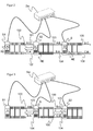
- the FIG. 1 schematically shows an automation system, which is constructed from a first controller S1 and a second controller S2 and from a first actuator controlled by the first controller S1 and a second actuator controlled by the second controller S2.
- the first controller S1 controls the first actuator shown by way of example as a robot arm R.
- the second controller S2 controls the second actuator, exemplified as a punch St.
- the first and second controllers S1 and S2 are connected to one another in a communication line 100 and communicate by means of a first transmission connection 101 and a second transmission connection 102.
- the first controller S1 communicates by means of the first transmission link 101 with the second controller S2.
- the second controller S2 communicates by means of the second transmission connection 102 with the first controller S1.
- the first and second controllers S1 and S2 each have a unique identifier.
- the first controller S1 has the identifier A and the second controller S2 has the identifier C.
- the identifier is used for the controllers S1 and S2 as addressing for identifying the controllers S1 and S2 in the communication line 100, so that by means of the identifier preferably the position and the Task of the associated controls S1 and S2 in the communication line 100 can be communicated. That with the identifier A and C, the order of the controllers S1 and S2 in the communication line 100 is uniquely determined, so that a network of the first and second controllers S1 and S2 is formed.
- Each controller S1 and S2 has an input unit I1 and I2 and an output unit 01 and 02 to communicate with each other. Furthermore, each controller S1 and S2 has a computer unit RE, which serves to detect the identifier A and C of the connected controller S1 and S2.
- the computer unit RE creates from the identifiers A and C of the connected controllers S1 and S2 of the communication line 100 for the transmission links 101 of the first controller S1 a first identifier pair A: C and for the transmission connection 102 of the second controller S2 a second identifier pair C: A.
- the computer unit RE stores the created identity pairs A: C and C: A in a memory unit of the respective first and second controllers S1 and S2, so that the first and second transmission connections 101 and 102 of the controllers S1 and S2 are known and uniquely assignable.
- FIG. 2 schematically shows an inventive addition of a controller S to be added to the described communication line 100 between the first and second controllers S1 and S2.
- the controller S to be added has an identifier B.
- the method according to the invention provides for the controller S to be added a fourth transmission connection 104, which is intended to enable communication of the controller S to be added with the first controller S1.
- a third transmission link 103 between the controller S to be added and the first controller S1 are provided, wherein the first controller S1 can communicate with the controller S to be added via the third transmission connection 103.
- the computer unit RE of the controllers S1 and S generates from the identifiers of the first controller S1 and S to be added for the respective transmission connections 103 and 104 a corresponding identification pair A: B and B: A. That for the third transmission link 103, the computing unit RE stores a third identifier pair, which is A: B, into the memory unit. For the fourth transmission link 104, the computing unit RE stores a fourth identifier pair, which is B: A, into the memory unit.
- the third and fourth transmission connections 103 and 104 can be unambiguously assigned for the first controller S1 and S to be added in the network.
- the method according to the invention provides a fifth transmission link 105 for the controller S to be added, which is intended to enable communication of the controller S to be added with the second controller S2.
- the computer unit RE creates a fifth identifier pair, which is B: C, for the fifth transmission connection 105 and stores this in the memory unit of the controller S to be added.
- a sixth transmission link 106 between the controller S to be added and the second controller S2 is provided, via which the second controller S2 can communicate with the controller S to be added.
- the computer unit RE From the identifier B and C of the controllers S2 and S to be connected, the computer unit RE creates a sixth identification pair, which is C: B, and stores this into the memory unit of the controller S to be added.
- a willingness to add the controller S to be added to the communication line 100 is advantageously communicated by the controller S to be added so that during operation of the network the third to sixth transmission links 103 to 106 are activated between the first, second and controller S1, S2 and S to be added and the existing first and second transmission links 101 and 102 between the first and second controllers S1 and S2 are deactivated.
- the controller S to be added is added without communication interruption of the network between the first and second controllers S1 and S2.
- the transmission links 101 to 106 are uniquely assignable.
- the network is not limited to two controllers S1 and S2.
- the network may include a plurality of controllers connected to an Ethernet based communication line, particularly in series.
- FIG. 4 shows an alternative embodiment of the method according to the invention for removing a control from a network of three controllers of an automation system.
- the inventive method is not limited to the number of three controllers in the network.
- the number of connected controllers can be any number.
- the illustrated automation system has three controls, which are connected in series to a communication line 100.
- the first controller S1 has a third transmission connection 103 to the controller S to be removed, via which the first controller S1 communicates with the controller S to be removed.
- the controller S to be removed has a fourth transmission connection 104 to the first controller S1, via which the controller S to be removed communicates with the first controller S1.
- the computer unit RE creates a third and fourth identifier pair from the identifiers A and B of the first and to-be-removed controllers S1 and S for the third and fourth transmission links 103 and 104, the third identifier pair being A: B and the fourth identifier pair B: A ,
- the identifier pairs A: B and B: A are stored in the respective controllers S1 and S.
- the controller S to be removed further has a fifth transmission link 105 to the second controller S2, via which the controller S to be removed communicates with the second controller S2.
- the second controller S2 has a sixth transmission connection 106 to the controller S to be removed, via which the second controller S2 communicates with the controller S to be removed.
- the computer unit RE creates from the identifiers B and C of the second and to be removed control S2 and S for the fifth and sixth transmission link 105 and 106 respectively a fifth and sixth identifier pair, the fifth identifier pair B: C and the sixth identifier pair C: B read ,
- the identifier pairs B: C and C: B are stored in the respective controllers S2 and S.
- the method according to the invention provides that the first controller S1 sets up a first transmission connection 101 to the second controller S2, the established first transmission connection 101 being inactive for the communication line 100 , Furthermore, a second transmission link 102 from the second controller S2 to the first controller S1 provided by the inventive method. The second transmission link 102 remains initially inactive for the communication line 100.
- the computer unit RE creates from identifiers A and C of the first and second controllers S1 and S2 for the respective first and second transmission links 101 and 102 a corresponding first and second identifier pair, the first identifier pair A: C and the second identifier pair C: A reads.
- the first and second identifier pair A: C and C: A are stored in the first and second controllers S1 and S2.
- first and second transmission links 101 and 102 After establishing the first and second transmission links 101 and 102 between the first and second controllers S1 and S2, removal of the controller S to be removed may be performed during ongoing operation of the communication line 100 of the network.
- the first and second transmission links 101 and 102 are activated between the first and second controls S1 and S2, wherein at the same time the third to sixth transmission link 103 to 106 between the controller S to be removed and the first controller S1 upstream of the controller S to be removed the control S to be removed downstream of the second control S2 are deactivated.
- the controller S to be removed is thus removed from the communication line 100 of the network.
- the communication between the first and second controllers S1 and S2 of the remaining communication line 100 of the network remains uninterrupted via the first and second transmission links 101 and 102.
- the inventive method for adding or removing a controller S are stored or stored in particular as programs in the controllers S1, S2 and S.
- the controllers S1, S2 and S are preferably connected to an Ethernet-based switch Sw and connected to one another via the switch Sw.
- the controller S to be added or removed is able to pick up or remove it from the communication line 100 communicate the communication line 100 of the network to the first and second controllers S1 and S2, so that the corresponding inventive method can be activated.
Landscapes
- Engineering & Computer Science (AREA)
- Computer Networks & Wireless Communication (AREA)
- Signal Processing (AREA)
- Small-Scale Networks (AREA)
Description
- Die Erfindung betrifft ein Verfahren zum Hinzufügen einer Steuerung in ein Netzwerk gemäß dem Anspruch 1 und ein Verfahren zum Entfernen einer Steuerung aus einem Netzwerk gemäß dem Anspruch 5 sowie eine Vorrichtung zum Durchführen der Verfahren gemäß dem Anspruch 9.
- In der heutigen Automatisierungsindustrie wird eine Gesamtanlage aus einer Vielzahl von Modulen erstellt, wobei jedes Modul zumindest eine Steuerung und zumindest einen Aktor aufweist. Durch den modularen Aufbau der Anlage kann eine Änderung der Anlage einfach und zeitsparend durchgeführt werden.
- Die Steuerungen steuern derart die Aktoren, so dass die Aktoren ihre zugeordnete Aufgabe durchführen und gegebenenfalls miteinander interagieren. Hierzu sind die Steuerungen über ein Kommunikationsnetzwerk, vorzugsweise ein auf Ethernet basiertes Netzwerk, miteinander verbunden. Das Kommunikationsnetzwerk kann durch eine übergeordnete zentrale Steuerung gesteuert werden oder durch eine Linienvernetzung der beteiligten Steuerungen aufgebaut sein, d.h. die beteiligten Steuerungen sind in einer Kommunikationslinie (Line Konzept) miteinander verbunden.
- Bei der Erstellung oder der Änderung der Gesamtanlage muss die gesamte Anlage entsprechend dem automatisierten Ablaufprozess programmiert bzw. neu konfiguriert werden.
- Bei einer zentralen Steuerung des Kommunikationsnetzwerks muss ein Maximalausbau bzw. alle unterschiedlichen Modulzusammenstellungen der Gesamtanlage bekannt und in der zentralen Steuerung hinterlegt sein. Eine Änderung der Gesamtanlage, zum Beispiel durch Hinzufügen einer weiteren Steuerung bzw. durch Entfernen einer bestehenden Steuerung, erfordert eine Unterbrechung der Kommunikation der Gesamtanlage, damit die geänderten Kommunikationswege in dem Kommunikationsnetzwerk in der zentralen Steuerung implementiert werden können.
- Bei einer Linienvernetzung der beteiligten Steuerungen erfordert eine Änderung im Aufbau der Gesamtanlage, zum Beispiel durch Hinzufügen einer weiteren Steuerung bzw. durch Entfernen einer bestehenden Steuerung, ebenfalls eine Unterbrechung der Kommunikation der Gesamtanlage. Hierbei kann eine Anpassung der Verkabelung der Kommunikationslinie erforderlich sein. Ferner müssen die benachbarten Steuerungen der hinzugefügten Steuerung bzw. der entfernten Steuerung bezüglich ihrer Kommunikation in der Kommunikationslinie neu eingelernt werden.
- Es ist daher eine Aufgabe der Erfindung, ein Verfahren zum Hinzufügen einer Steuerung in ein Netzwerk bzw. ein Verfahren zum Entfernen einer Steuerung aus einem Netzwerk zur Verfügung zu stellen, das das Hinzufügen bzw. das Entfernen ohne eine Unterbrechung der laufenden Kommunikation der Kommunikationslinie ermöglicht. Ferner ist es eine Aufgabe der Erfindung eine Steuerung zum Durchführen eines Verfahrens zum Hinzufügen einer Steuerung in ein Netzwerk bzw. eines Verfahrens zum Entfernen einer Steuerung aus einem Netzwerk zur Verfügung zu stellen, die das durchführen der Verfahren ohne eine Unterbrechung der laufenden Kommunikation der Kommunikationslinie ermöglicht.
- Die Aufgabe wird erfindungsgemäß gelöst durch ein Verfahren zum Hinzufügen einer Steuerung in ein Netzwerk von zumindest einer ersten und zweiten Steuerung, die zum Betreiben von Aktoren vorgesehen sind, während eines Betriebs des Netzwerks, wobei die erste und zweite Steuerung in einer Kommunikationslinie miteinander verbunden sind und über eine erste Sendeverbindung der ersten Steuerung und eine zweite Sendeverbindung der zweiten Steuerung miteinander kommunizieren, und wobei jede Steuerung eine eindeutige Kennung aufweist, mit den Schritten Vorsehen einer dritten Sendeverbindung und einer vierten Sendeverbindung zwischen der hinzuzufügenden Steuerung und der die hinzuzufügende Steuerung vorzuschaltenden ersten Steuerung, Vorsehen einer fünften Sendeverbindung und einer sechsten Sendeverbindung zwischen der hinzuzufügenden Steuerung und der die hinzuzufügende Steuerung nachzuschaltenden zweiten Steuerung, und Aktivieren der dritten bis sechsten Sendeverbindungen zwischen der ersten, zweiten und hinzuzufügenden Steuerung beim gleichzeitigen Deaktivieren der ersten und zweiten Sendeverbindung zwischen der ersten und zweiten Steuerung.
- Gemäß einem bevorzugten Ausführungsbeispiel werden jeweils ein drittes und viertes Kennungspaar für die Sendeverbindungen zwischen der hinzuzufügenden Steuerung und der ersten Steuerung aus den jeweiligen Kennungen der hinzuzufügenden und ersten Steuerung definiert.
- Gemäß einem weiteren bevorzugten Ausführungsbeispiel werden das dritte und vierte Kennungspaar in der hinzuzufügenden und der ersten Steuerung abgespeichert. Dies hat den Vorteil, dass über die definierten Kennungspaare die Kommunikationsverbindungen für die in der Kommunikationslinie verbundenen Steuerungen eindeutig sind.
- Gemäß einem weiteren bevorzugten Ausführungsbeispiel werden jeweils ein fünftes und sechstes Kennungspaar für die Sendeverbindungen zwischen der hinzuzufügenden Steuerung und der zweiten Steuerung aus den jeweiligen Kennungen der hinzuzufügenden und zweiten Steuerung definiert. Vorteilhafterweise werden das fünfte und sechste Kennungspaar in der hinzuzufügenden und der zweiten Steuerung abgespeichert.
- Hieraus ergibt sich der Vorteil, dass die Kommunikationsverbindungen zwischen der hinzuzufügenden Steuerung und der vorgeschalteten Steuerung bzw. der nachgeschalteten Steuerung über die definierten Kennungspaare eindeutig bestimmbar sind.
- Die Aufgabe wird erfindungsgemäß ferner gelöst durch ein Verfahren zum Entfernen einer Steuerung aus einem Netzwerk von zumindest einer ersten und zweiten Steuerung und der zu entfernenden Steuerung, die zum Betreiben von Aktoren vorgesehen sind, während eines Betriebs des Netzwerks, wobei die Steuerungen in einer Kommunikationslinie miteinander verbunden sind, die zu entfernende Steuerung zwischen der ersten und zweiten Steuerung angeordnet ist, die erste Steuerung über eine dritte Sendeverbindung mit der zu entfernenden Steuerung verbunden ist, die zu entfernende Steuerung über eine vierte Sendeverbindung mit der ersten Steuerung und über eine fünfte Sendeverbindung mit der zweiten Steuerung verbunden ist und die zweite Steuerung über eine sechste Sendeverbindung mit der zu entfernenden Steuerung verbunden ist, und wobei jede Steuerung eine eindeutige Kennung aufweist, mit den Schritten Vorsehen einer ersten Sendeverbindung und einer zweiten Sendeverbindung zwischen der ersten und zweiten Steuerung, und Aktivieren der ersten und zweiten Sendeverbindung zwischen der ersten und zweiten Steuerung beim gleichzeitigen Deaktivieren der dritten bis sechsten Sendeverbindungen zwischen der zu entfernenden Steuerung und der die zu entfernende Steuerung vorgeschalteten ersten Steuerung und der die zu entfernende Steuerung nachgeschalteten zweiten Steuerung.
- Gemäß einem bevorzugten Ausführungsbeispiel werden jeweils ein erstes und zweites Kennungspaar für die erste und zweite Sendeverbindung aus den jeweiligen Kennungen der ersten und zweiten Steuerung definiert.
- Gemäß einem weiteren bevorzugten Ausführungsbeispiel werden das erste und zweite Kennungspaar in der ersten und zweiten Steuerung abgespeichert.
- Die Aufgabe wird weiterhin erfindungsgemäß gelöst durch eine Steuerung zum Durchführen eines der obigen Verfahren, wobei die Steuerung in einem Netzwerk mit Steuerungen einfügbar oder entfernbar ist, umfassend eine Eingangs- und Ausgangseinheit zum Kommunizieren mit zumindest einer weiteren Steuerung, und eine Rechnereinheit zum Erkennen einer Kennung der weiteren Steuerung und zum Erstellen einer Sendeverbindung mit der weiteren Steuerung, wobei die Rechnereinheit ein Kennungspaar aus einer eigenen Kennung und der Kennung der weiteren Steuerung für die Sendeverbindung erstellt und das erstellte Kennungspaar in einer Speichereinheit abspeichert, und wobei die Rechnereinheit vorgesehen ist, zum Aktivieren oder Deaktivieren der Sendeverbindung zu der weiteren Steuerung während eines Betriebs des Netzwerks.
- Gemäß einem bevorzugten Ausführungsbeispiel ist die Steuerung an einem auf Ethernet basierten Switch anschließbar und über den Switch mit der weiteren Steuerung verbindbar.
- Gemäß einem weiteren bevorzugten Ausführungsbeispiel kommuniziert die Rechnereinheit eine Bereitschaft zum Aktivieren der Sendeverbindungen nach der Erstellung derselben oder eine Bereitschaft zum Deaktivieren der Sendeverbindungen zu der anderen Steuerung.
- Das erfindungsgemäße Verfahren und die Steuerung können auf ähnliche Weise durch weitere Merkmale ausgestaltet werden und zeigen dabei ähnliche Vorteile. Derartige weitere Merkmale sind beispielhaft, aber nicht abschließend, in den sich an den unabhängigen Anspruch anschließenden Unteransprüchen beschrieben.
- Die Erfindung wird nachstehend auch hinsichtlich weiterer Vorteile und Merkmale unter Bezugnahme auf die beigefügte Zeichnung anhand von Ausführungsbeispielen erläutert. Die Figuren der Zeichnung zeigen in:
- Fig. 1
- eine schematische Darstellung einer Kommunikationslinie einer Automatisierungsanlage,
- Fig. 2, 3
- eine schematische Darstellung eines erfindungsgemäßen Hinzufügens einer Steuerung in die Kommunikationslinie der Automatisierungsanlage,
- Fig. 4, 5
- eine schematische Darstellung eines erfindungsgemäßen Entfernens einer Steuerung aus der Kommunikationslinie der Automatisierungsanlage.
- Die
Figur 1 zeigt schematisch eine Automatisierungsanlage, die aus einer ersten Steuerung S1 und einer zweiten Steuerung S2 und aus einem von der ersten Steuerung S1 angesteuerten ersten Aktor und einem von der zweiten Steuerung S2 angesteuerten zweiten Aktor aufgebaut ist. Die erste Steuerung S1 steuert den, beispielhaft als Roboterarm R dargestellten, ersten Aktor an. Die zweite Steuerung S2 steuert den, beispielhaft als Stanze St dargestellten, zweiten Aktor an. - Die erste und zweite Steuerung S1 und S2 sind in einer Kommunikationslinie 100 miteinander verbunden und kommunizieren mittels einer ersten Sendeverbindung 101 und einer zweiten Sendeverbindung 102. Hierbei kommuniziert die erste Steuerung S1 mittels der ersten Sendeverbindung 101 mit der zweiten Steuerung S2. Die zweite Steuerung S2 kommuniziert mittels der zweiten Sendeverbindung 102 mit der ersten Steuerung S1.
- Die erste und zweite Steuerung S1 und S2 weisen jeweils eine eindeutige Kennung auf. Die erste Steuerung S1 hat die Kennung A und die zweite Steuerung S2 hat die Kennung C. Die Kennung dient den Steuerungen S1 und S2 als Adressierung zur Identifizierung der Steuerungen S1 und S2 in der Kommunikationslinie 100, so dass mittels der Kennung vorzugsweise die Position und die Aufgabe der zugehörigen Steuerungen S1 und S2 in der Kommunikationslinie 100 mitgeteilt werden können. D.h. mit der Kennung A und C ist die Reihenfolge der Steuerungen S1 und S2 in der Kommunikationslinie 100 eindeutig bestimmt, so dass ein Netzwerk aus den ersten und zweiten Steuerungen S1 und S2 gebildet ist.
- Jede Steuerung S1 und S2 weist eine Eingangseinheit I1 und I2 und eine Ausgangseinheit 01 und 02 auf, um miteinander zu kommunizieren. Ferner weist jede Steuerung S1 und S2 eine Rechnereinheit RE auf, die zum Erkennen der Kennung A und C der verbundenen Steuerung S1 und S2 dient. Die Rechnereinheit RE erstellt aus den Kennungen A und C der verbundenen Steuerungen S1 und S2 der Kommunikationslinie 100 für die Sendeverbindungen 101 der ersten Steuerung S1 ein erstes Kennungspaar A:C und für die Sendeverbindung 102 der zweiten Steuerung S2 ein zweites Kennungspaar C:A. Die Rechnereinheit RE speichert die erstellten Kennungspaare A:C und C:A in einer Speichereinheit der jeweiligen ersten und zweiten Steuerung S1 und S2, so dass die erste und zweite Sendeverbindung 101 und 102 der Steuerungen S1 und S2 bekannt und eindeutig zuordenbar sind.
- In der
Figur 2 wird schematisch ein erfindungsgemäßes Hinzufügen einer hinzuzufügenden Steuerung S in die beschriebene Kommunikationslinie 100 zwischen der ersten und zweiten Steuerung S1 und S2 gezeigt. Die hinzuzufügende Steuerung S weist eine Kennung B auf. - Das erfindungsgemäße Verfahren sieht für die hinzuzufügende Steuerung S eine vierte Sendeverbindung 104 vor, die eine Kommunikation der hinzuzufügenden Steuerung S zu der ersten Steuerung S1 ermöglichen soll. Eine dritte Sendeverbindung 103 zwischen der hinzuzufügenden Steuerung S und der ersten Steuerung S1 wird vorgesehen, wobei über die dritte Sendeverbindung 103 die erste Steuerung S1 mit der hinzuzufügenden Steuerung S kommunizieren kann.
- Die Rechnereinheit RE der Steuerungen S1 und S erstellt aus den Kennungen der ersten und hinzuzufügenden Steuerung S1 und S für die jeweiligen Sendeverbindungen 103 und 104 ein entsprechendes Kennungspaar A:B und B:A. D.h. für die dritte Sendeverbindung 103 speichert die Rechnereinheit RE ein drittes Kennungspaar, das A:B lautet, in die Speichereinheit ab. Für die vierte Sendeverbindung 104 speichert die Rechnereinheit RE ein viertes Kennungspaar, das B:A lautet, in die Speichereinheit ab.
- Mittels der Kennungspaare A:B und B:A lassen sich die dritte und vierte Sendeverbindung 103 und 104 für die erste und hinzuzufügende Steuerung S1 und S in dem Netzwerk eindeutig zuordnen.
- Weiterhin sieht das erfindungsgemäße Verfahren eine fünfte Sendeverbindung 105 für die hinzuzufügende Steuerung S vor, die eine Kommunikation der hinzuzufügenden Steuerung S zu der zweiten Steuerung S2 ermöglichen soll. Aus den jeweiligen Kennungen B und C erstellt die Rechnereinheit RE ein fünftes Kennungspaar, das B:C lautet, für die fünfte Sendeverbindung 105 und speichert dieses in die Speichereinheit der hinzuzufügenden Steuerung S ab.
- Eine sechste Sendeverbindung 106 zwischen der hinzuzufügenden Steuerung S und der zweiten Steuerung S2 wird vorgesehen, über die die zweite Steuerung S2 mit der hinzuzufügenden Steuerung S kommunizieren kann. Aus der Kennung B und C der zu verbindenden Steuerungen S2 und S erstellt die Rechnereinheit RE ein sechstes Kennungspaar, das C:B lautet, und speichert dieses in die Speichereinheit der hinzuzufügenden Steuerung S ab.
- Nach der Erstellung der dritten bis sechsten Sendeverbindungen 103 bis 106 sind die notwendigen Verbindungen für die Kommunikationslinie 100 aufgebaut und ein Hinzufügen der hinzuzufügenden Steuerung S zwischen der ersten und zweiten Steuerung S1 und S2 ist möglich.
- Eine Bereitschaft des Hinzufügens der hinzuzufügenden Steuerung S in die Kommunikationslinie 100 wird vorteilhafterweise von der hinzuzufügenden Steuerung S kommuniziert, so dass während des Betriebs des Netzwerks die dritte bis sechste Sendeverbindungen 103 bis 106 zwischen der ersten, zweiten und hinzuzufügenden Steuerung S1, S2 und S aktiviert werden und die bestehende erste und zweite Sendeverbindung 101 und 102 zwischen der ersten und zweiten Steuerung S1 und S2 deaktiviert werden.
- Durch das gleichzeitige Aktivieren der neu vorgesehenen Sendeverbindungen 103 bis 106 und Deaktivieren der bestehenden Sendeverbindungen 101 und 102 wird, wie in
Figur 3 gezeigt, die hinzuzufügende Steuerung S ohne eine Kommunikationsunterbrechung des Netzwerks zwischen der ersten und zweiten Steuerung S1 und S2 hinzugefügt. - Durch die abgespeicherten Kennungspaare der Sendeverbindungen 101 bis 106 sind die Sendeverbindungen 101 bis 106 für alle verbundenen Steuerungen S1, S2 und S eindeutig zuordenbar.
- Gemäß dem erfindungsgemäßen Verfahren ist das Netzwerk nicht auf zwei Steuerungen S1 und S2 beschränkt. Das Netzwerk kann eine Vielzahl von Steuerungen aufweisen, die an eine auf Ethernet basierte Kommunikationslinie, insbesondere in Reihe geschaltet, verbunden sind.
- Die
Figur 4 zeigt eine alternative Ausgestaltung des erfindungsgemäßen Verfahrens zum Entfernen einer Steuerung aus einem Netzwerk von drei Steuerungen einer Automatisierungsanlage. Hierbei ist das erfindungsgemäße Verfahren nicht auf die Anzahl von drei Steuerungen in dem Netzwerk beschränkt. Die Anzahl der angeschlossenen Steuerungen kann beliebig hoch sein. - Die der Automatisierungsanlage zugehörigen Aktoren sind aus Übersichtlichkeitsgründen nicht dargestellt und die gleichen Komponenten zu den vorherigen Figuren weisen die gleichen Bezugszeichen auf.
- Die dargestellte Automatisierungsanlage weist drei Steuerungen auf, die in Reihe an einer Kommunikationslinie 100 angeschlossen sind. Die erste Steuerung S1 weist eine dritte Sendeverbindung 103 zu der zu entfernenden Steuerung S auf, über die die erste Steuerung S1 mit der zu entfernenden Steuerung S kommuniziert. Die zu entfernende Steuerung S weist eine vierte Sendeverbindung 104 zu der ersten Steuerung S1 auf, über die die zu entfernende Steuerung S mit der ersten Steuerung S1 kommuniziert.
- Die Rechnereinheit RE erstellt aus den Kennungen A und B der ersten und zu entfernenden Steuerung S1 und S für die dritte und vierte Sendeverbindung 103 und 104 jeweils ein drittes und viertes Kennungspaar, wobei das dritte Kennungspaar A:B und das vierte Kennungspaar B:A lauten. Die Kennungspaare A:B und B:A sind in den jeweiligen Steuerungen S1 und S abgespeichert.
- Die zu entfernende Steuerung S weist ferner eine fünfte Sendeverbindung 105 zu der zweiten Steuerung S2 auf, über die die zu entfernende Steuerung S mit der zweiten Steuerung S2 kommuniziert. Auf der anderen Seite weist die zweite Steuerung S2 eine sechste Sendeverbindung 106 zu der zu entfernenden Steuerung S auf, über die die zweite Steuerung S2 mit der zu entfernenden Steuerung S kommuniziert.
- Die Rechnereinheit RE erstellt aus den Kennungen B und C der zweiten und zu entfernenden Steuerung S2 und S für die fünfte und sechste Sendeverbindung 105 und 106 jeweils ein fünftes und sechstes Kennungspaar, wobei das fünfte Kennungspaar B:C und das sechste Kennungspaar C:B lauten. Die Kennungspaare B:C und C:B sind in den jeweiligen Steuerungen S2 und S abgespeichert.
- Über die vorgesehenen Sendeverbindungen 103 bis 106 bilden die erste, zweite und zu entfernende Steuerungen S1, S2 und S die Kommunikationslinie 100 der Automatisierungsanlage.
- Bei einer Änderung der Automatisierungsanlage durch Entfernen der zu entfernenden Steuerung S aus der Kommunikationslinie 100 sieht das erfindungsgemäße Verfahren vor, dass die erste Steuerung S1 eine erste Sendeverbindung 101 zu der zweiten Steuerung S2 aufbaut, wobei die aufgebaute erste Sendeverbindung 101 inaktiv für die Kommunikationslinie 100 ist. Weiterhin wird eine zweite Sendeverbindung 102 von der zweiten Steuerung S2 zu der ersten Steuerung S1 durch das erfindungsgemäße Verfahren vorgesehen. Auch die zweite Sendeverbindung 102 bleibt für die Kommunikationslinie 100 zunächst inaktiv.
- Die Rechnereinheit RE erstellt aus den Kennungen A und C der ersten und zweiten Steuerung S1 und S2 für die jeweilige erste und zweite Sendeverbindung 101 und 102 ein entsprechendes erstes und zweites Kennungspaar, wobei das erste Kennungspaar A:C lautet und das zweite Kennungspaar C:A lautet. Das erste und zweite Kennungspaar A:C und C:A werden in der ersten und zweiten Steuerung S1 und S2 abgespeichert.
- Nach der Erstellung der ersten und zweiten Sendeverbindung 101 und 102 zwischen der ersten und zweiten Steuerung S1 und S2 kann ein Entfernen der zu entfernenden Steuerung S während eines laufenden Betriebs der Kommunikationslinie 100 des Netzwerks durchgeführt werden. Hierzu werden die erste und zweite Sendeverbindung 101 und 102 zwischen der ersten und zweiten Steuerung S1 und S2 aktiviert, wobei gleichzeitig die dritte bis sechste Sendeverbindung 103 bis 106 zwischen der zu entfernenden Steuerung S und der die zu entfernende Steuerung S vorgeschalteten ersten Steuerung S1 und der die zu entfernende Steuerung S nachgeschalteten zweiten Steuerung S2 deaktiviert werden.
- Die zu entfernende Steuerung S ist somit aus der Kommunikationslinie 100 des Netzwerks entfernt. Die Kommunikation zwischen der ersten und zweiten Steuerung S1 und S2 der verbleibenden Kommunikationslinie 100 des Netzwerks bleibt über die erste und zweite Sendeverbindung 101 und 102 ohne Unterbrechung aufrecht.
- Die erfindungsgemäßen Verfahren zum Hinzufügen oder zum Entfernen einer Steuerung S sind insbesondere als Programme in den Steuerungen S1, S2 und S hinterlegt bzw. abgespeichert. Vorzugsweise sind die Steuerungen S1, S2 und S an einem auf Ethernet basierten Switch Sw angeschlossen und über den Switch Sw miteinander verbunden.
- Mittels eines Signals über den Switch Sw kann die hinzuzufügende oder zu entfernende Steuerung S ihre Aufnahme in die Kommunikationslinie 100 oder ihr Entfernen aus der Kommunikationslinie 100 des Netzwerks an die erste und zweite Steuerung S1 und S2 kommunizieren, so dass das entsprechende erfindungsgemäße Verfahren aktiviert werden kann.
-
- 100
- Kommunikationslinie
- 101
- erste Sendeverbindung
- 102
- zweite Sendeverbindung
- 103
- dritte Sendeverbindung
- 104
- vierte Sendeverbindung
- 105
- fünfte Sendeverbindung
- 106
- sechste Sendeverbindung
- A, B, C
- Kennung der Steuerungen
- A:B
- drittes Kennungspaar
- A:C
- erstes Kennungspaar
- B:A
- viertes Kennungspaar
- B:C
- fünftes Kennungspaar
- C:A
- zweites Kennungspaar
- C:B
- sechstes Kennungspaar
- I1, I2
- Eingangseinheit
- O1, O2
- Ausgangseinheit
- R
- Roboter
- RE
- Rechnereinheit
- S
- hinzuzufügende oder zu entfernende Steuerung
- S1
- erste Steuerung
- S2
- zweite Steuerung
- St
- Stanze
- Sw
- Switch
Claims (11)
- Verfahren zum Hinzufügen einer Steuerung (S) in ein Netzwerk von zumindest einer ersten und zweiten Steuerung (S1, S2), die zum Betreiben von Aktoren (R, St) vorgesehen sind, während eines Betriebs des Netzwerks, wobei die erste und zweite Steuerung (S1, S2) in einer Kommunikationslinie (100) miteinander verbunden sind und über eine erste Sendeverbindung (101) der ersten Steuerung (S1) und eine zweite Sendeverbindung (102) der zweiten Steuerung (S2) miteinander kommunizieren, und wobei jede Steuerung (S1, S2, S) eine eindeutige Kennung (A, C, B) aufweist, mit den Schritten:Vorsehen einer dritten Sendeverbindung (103) und einer vierten Sendeverbindung (104) zwischen der hinzuzufügenden Steuerung (S) und der die hinzuzufügende Steuerung (S) vorzuschaltenden ersten Steuerung (S1),Vorsehen einer fünften Sendeverbindung (105) und einer sechsten Sendeverbindung (106) zwischen der hinzuzufügenden Steuerung (S) und der die hinzuzufügende Steuerung (S) nachzuschaltenden zweiten Steuerung (S2), undAktivieren der dritten bis sechsten Sendeverbindungen (103 - 106) zwischen der ersten, zweiten und hinzuzufügenden Steuerung (S1, S2, S) beim gleichzeitigen Deaktivieren der ersten und zweiten Sendeverbindung (101, 102) zwischen der ersten und zweiten Steuerung (S1, S2).
- Verfahren nach Anspruch 1, wobei jeweils ein drittes und viertes Kennungspaar (A:B, B:A) für die Sendeverbindungen (103, 104) zwischen der hinzuzufügenden Steuerung (S) und der ersten Steuerung (S1) aus den jeweiligen Kennungen (A, B) der hinzuzufügenden und ersten Steuerung (S, S1) definiert werden.
- Verfahren nach Anspruch 2, wobei das dritte und vierte Kennungspaar (A:B, B:A) in der hinzuzufügenden und der ersten Steuerung (S, S1) abgespeichert werden.
- Verfahren nach einem der vorhergehenden Ansprüche 1 bis 3, wobei jeweils ein fünftes und sechstes Kennungspaar (B:C, C:B) für die Sendeverbindungen (105, 106) zwischen der hinzuzufügenden Steuerung (S) und der zweiten Steuerung (S2) aus den jeweiligen Kennungen (B, C) der hinzuzufügenden und zweiten Steuerung (S, S2) definiert werden.
- Verfahren nach Anspruch 4, wobei das fünfte und sechste Kennungspaar (B:C, C:B) in der hinzuzufügenden und der zweiten Steuerung (S, S2) abgespeichert werden.
- Verfahren zum Entfernen einer Steuerung (S) aus einem Netzwerk von zumindest einer ersten und zweiten Steuerung (S1, S2) und der zu entfernenden Steuerung (S), die zum Betreiben von Aktoren (R, St) vorgesehen sind, während eines Betriebs des Netzwerks, wobei die Steuerungen (S1, S2, S) in einer Kommunikationslinie (100) miteinander verbunden sind, die zu entfernende Steuerung (S) zwischen der ersten und zweiten Steuerung (S1, S2) angeordnet ist, die erste Steuerung (S1) über eine dritte Sendeverbindung (103) mit der zu entfernenden Steuerung (S) verbunden ist, die zu entfernende Steuerung (S) über eine vierte Sendeverbindung (104) mit der ersten Steuerung (S1) und über eine fünfte Sendeverbindung (105) mit der zweiten Steuerung (S2) verbunden ist und die zweite Steuerung (S2) über eine sechste Sendeverbindung (106) mit der zu entfernenden Steuerung (S) verbunden ist, und wobei jede Steuerung (S1, S2, S) eine eindeutige Kennung (A, C, B) aufweist, mit den Schritten:Vorsehen einer ersten Sendeverbindung (101) und einer zweiten Sendeverbindung (102) zwischen der ersten und zweiten Steuerung (S1, S2), undAktivieren der ersten und zweiten Sendeverbindung (101, 102) zwischen der ersten und zweiten Steuerung (S1, S2) beim gleichzeitigen Deaktivieren der dritten bis sechsten Sendeverbindungen (103 - 106) zwischen der zu entfernenden Steuerung (S) und der die zu entfernende Steuerung (S) vorgeschalteten ersten Steuerung (S1) und der die zu entfernende Steuerung (S) nachgeschalteten zweiten Steuerung (S2).
- Verfahren nach Anspruch, wobei jeweils ein erstes und zweites Kennungspaar (A:C, C:A) für die erste und zweite Sendeverbindung (101, 102) aus den jeweiligen Kennungen (A, C) der ersten und zweiten Steuerung (S1, S2) definiert werden.
- Verfahren nach Anspruch 7, wobei das erste und zweite Kennungspaar (A:C, C:A) in der ersten und zweiten Steuerung (S1, S2) abgespeichert werden.
- Steuerung (S1, S2, S) zum Durchführen eines Verfahrens nach einem der Ansprüche 1 bis 8, wobei die Steuerung (S1, S2, S) in einem Netzwerk mit Steuerungen (S1, S2, S) einfügbar oder entfernbar ist, umfassend:eine Eingangs- und Ausgangseinheit (I1, I2; 01, 02) zum Kommunizieren mit zumindest einer weiteren Steuerung (S1, S2, S), undeine Rechnereinheit (RE) zum Erkennen einer Kennung (A, C, B) der weiteren Steuerung (S1, S2, S) und zum Erstellen einer Sendeverbindung (101 - 106) mit der weiteren Steuerung (S1, S2, S), wobei die Rechnereinheit (RE) ein Kennungspaar (A:C, C:A, A:B, B:A, B:C, C:B) aus einer eigenen Kennung (A, C, B) und der Kennung (A, C, B) der weiteren Steuerung (S1, S2, S) für die Sendeverbindung (101 - 106) erstellt und das erstellte Kennungspaar (A:C, C:A, A:B, B:A, B:C, C:B) in einer Speichereinheit abspeichert,und wobei die Rechnereinheit (RE) vorgesehen ist, zum Aktivieren oder Deaktivieren der Sendeverbindung (101 - 106) zu der weiteren Steuerung (S1, S2, S) während eines Betriebs des Netzwerks.
- Steuerung (S1, S2, S) nach Anspruch 9, wobei die Steuerung (S1, S2, S) an einem auf Ethernet basierten Switch (Sw) anschließbar und über den Switch (Sw) mit der weiteren Steuerung (S1, S2, S) verbindbar ist.
- Steuerung (S1, S2, S) nach Anspruch 9 oder 10, wobei die Rechnereinheit (RE) eine Bereitschaft zum Aktivieren der Sendeverbindungen (101 - 106) nach der Erstellung derselben oder eine Bereitschaft zum Deaktivieren der Sendeverbindungen (101 - 106) zu der anderen Steuerung (S1, S2, S) kommuniziert.
Priority Applications (2)
| Application Number | Priority Date | Filing Date | Title |
|---|---|---|---|
| EP15186611.8A EP3148121B1 (de) | 2015-09-24 | 2015-09-24 | Verfahren zum hinzufügen oder zum entfernen einer steuerung in ein/aus einem netzwerk und vorrichtung zum durchführen der verfahren |
| US15/273,578 US9949307B2 (en) | 2015-09-24 | 2016-09-22 | Methods of adding or removing a control into/out of a network and apparatus for carrying out said methods |
Applications Claiming Priority (1)
| Application Number | Priority Date | Filing Date | Title |
|---|---|---|---|
| EP15186611.8A EP3148121B1 (de) | 2015-09-24 | 2015-09-24 | Verfahren zum hinzufügen oder zum entfernen einer steuerung in ein/aus einem netzwerk und vorrichtung zum durchführen der verfahren |
Publications (2)
| Publication Number | Publication Date |
|---|---|
| EP3148121A1 true EP3148121A1 (de) | 2017-03-29 |
| EP3148121B1 EP3148121B1 (de) | 2017-11-08 |
Family
ID=54251965
Family Applications (1)
| Application Number | Title | Priority Date | Filing Date |
|---|---|---|---|
| EP15186611.8A Active EP3148121B1 (de) | 2015-09-24 | 2015-09-24 | Verfahren zum hinzufügen oder zum entfernen einer steuerung in ein/aus einem netzwerk und vorrichtung zum durchführen der verfahren |
Country Status (2)
| Country | Link |
|---|---|
| US (1) | US9949307B2 (de) |
| EP (1) | EP3148121B1 (de) |
Citations (3)
| Publication number | Priority date | Publication date | Assignee | Title |
|---|---|---|---|---|
| US20040133721A1 (en) * | 2002-04-26 | 2004-07-08 | Ellerbrock Philip J. | Systems and methods for assigning an address to a network device added to an existing network |
| WO2011002397A1 (en) * | 2009-06-30 | 2011-01-06 | Telefonaktiebolaget Lm Ericsson (Publ) | Method and arrangement handling pluggable modules and operating modes in a media converter system |
| DE102011086054A1 (de) * | 2011-11-10 | 2013-05-16 | Endress + Hauser Gmbh + Co. Kg | System zur Sicherstellung der Verfügbarkeit eines Bussystems der Automatisierungstechnik |
Family Cites Families (6)
| Publication number | Priority date | Publication date | Assignee | Title |
|---|---|---|---|---|
| US3938017A (en) * | 1974-03-05 | 1976-02-10 | Johnson Service Company | Anti-reset windup proportional and integral controller |
| US7725025B2 (en) * | 2006-07-06 | 2010-05-25 | Verizon Patent And Licensing Inc. | Switchable fiber termination |
| US8614596B2 (en) * | 2011-02-28 | 2013-12-24 | Medtronic Minimed, Inc. | Systems and methods for initializing a voltage bus and medical devices incorporating same |
| US9113348B2 (en) * | 2011-12-09 | 2015-08-18 | Qualcomm Incorporated | Compressed mode measurements for flexible bandwidth carrier systems, devices, and methods |
| US9054463B2 (en) * | 2013-09-20 | 2015-06-09 | Avedis Kifedjian | Audio interface connector with ground lift, kit, system and method of use |
| US9979791B2 (en) * | 2015-09-18 | 2018-05-22 | Avigilon Corporation | Physical security system having multiple server nodes configured to implement a conditionally triggered rule |
-
2015
- 2015-09-24 EP EP15186611.8A patent/EP3148121B1/de active Active
-
2016
- 2016-09-22 US US15/273,578 patent/US9949307B2/en active Active
Patent Citations (3)
| Publication number | Priority date | Publication date | Assignee | Title |
|---|---|---|---|---|
| US20040133721A1 (en) * | 2002-04-26 | 2004-07-08 | Ellerbrock Philip J. | Systems and methods for assigning an address to a network device added to an existing network |
| WO2011002397A1 (en) * | 2009-06-30 | 2011-01-06 | Telefonaktiebolaget Lm Ericsson (Publ) | Method and arrangement handling pluggable modules and operating modes in a media converter system |
| DE102011086054A1 (de) * | 2011-11-10 | 2013-05-16 | Endress + Hauser Gmbh + Co. Kg | System zur Sicherstellung der Verfügbarkeit eines Bussystems der Automatisierungstechnik |
Also Published As
| Publication number | Publication date |
|---|---|
| US9949307B2 (en) | 2018-04-17 |
| US20170094705A1 (en) | 2017-03-30 |
| EP3148121B1 (de) | 2017-11-08 |
Similar Documents
| Publication | Publication Date | Title |
|---|---|---|
| EP2317410B1 (de) | Sicherheitssteuerung | |
| EP2940926B1 (de) | Verfahren zur Konfiguration eines Kommunikationsgeräts innerhalb eines industriellen Automatisierungssystems und Verteilereinheit für einen Konfigurationsserver eines industriellen Kommunikationsnetzes | |
| EP1657608B1 (de) | Verfahren und Vorrichtung zum Betreiben eines Netzwerkes | |
| WO2013004382A1 (de) | Verfahren zur konfigurierung eines kommunikationsschnittstellenmoduls in einem steuerungs- oder automatisierungssystems | |
| DE102016012333A1 (de) | Robotersystem mit einer Vielzahl von vernetzten Controllern | |
| EP2713563A1 (de) | Redundant betreibbares industrielles Kommunikationssystem, Kommunikationsgerät und Verfahren zum redundanten Betrieb eines industriellen Kommunikationssystems | |
| DE102007025892A1 (de) | Werkzeugerkennung im Profinet | |
| EP3414632B1 (de) | Verfahren und vorrichtung zum überwachen einer datenverarbeitung und -übertragung in einer sicherheitskette eines sicherheitssystems | |
| EP2246756B1 (de) | Verfahren und Bediengerät zum Bedienen einer sicherheitsgerichteten industriellen Automatisierungskomponente | |
| EP2520991A1 (de) | Verfahren zum steuernden Eingriff in das Verhalten eines Submoduls | |
| EP1589386A1 (de) | Prozesssteuerung | |
| EP2375636A1 (de) | Vorrichtung und Verfahren zum Konfigurieren eines Bussystems | |
| EP3470939B1 (de) | Verfahren und system zum überwachen der sicherheitsintegrität einer durch ein sicherheitssystem bereitgestellten sicherheitsfunktion | |
| EP3470937B1 (de) | Verfahren und vorrichtungen zum überwachen der reaktionszeit einer durch ein sicherheitssystem bereitgestellten sicherheitsfunktion | |
| EP3148121B1 (de) | Verfahren zum hinzufügen oder zum entfernen einer steuerung in ein/aus einem netzwerk und vorrichtung zum durchführen der verfahren | |
| EP3133447B1 (de) | Sicherheitsschalter | |
| DE19905841A1 (de) | Vorrichtung zum Verarbeiten sicherheitsrelevanter Daten | |
| DE102006004339A1 (de) | Redundantes Kommunikationsnetzwerk | |
| EP3388902B1 (de) | Sicherheitsgerichtetes automatisierungssystem | |
| EP2283426B1 (de) | Verfahren und vorrichtung zur korrektur von digital übertragenen informationen | |
| DE10248100A1 (de) | Sicherheitsgerichtete Vorrichtung zum Anschluss von Feldgeräten an einen Feldbus | |
| DE102016117169B4 (de) | System zur Energie- und/oder Datenübertragung | |
| EP2315090B1 (de) | Echtzeitsteuerverfahren für eine Steuerungseinrichtung eines industriellen technischen Prozesses und Echtzeitbetriebsverfahren für eine Recheneinrichtung | |
| EP3270238A1 (de) | Verfahren zur steuerung eines antriebs | |
| EP1921525B1 (de) | Verfahren zum Betrieb einer sicherheitsgerichteten Anlage |
Legal Events
| Date | Code | Title | Description |
|---|---|---|---|
| PUAI | Public reference made under article 153(3) epc to a published international application that has entered the european phase |
Free format text: ORIGINAL CODE: 0009012 |
|
| 17P | Request for examination filed |
Effective date: 20160413 |
|
| AK | Designated contracting states |
Kind code of ref document: A1 Designated state(s): AL AT BE BG CH CY CZ DE DK EE ES FI FR GB GR HR HU IE IS IT LI LT LU LV MC MK MT NL NO PL PT RO RS SE SI SK SM TR |
|
| AX | Request for extension of the european patent |
Extension state: BA ME |
|
| GRAP | Despatch of communication of intention to grant a patent |
Free format text: ORIGINAL CODE: EPIDOSNIGR1 |
|
| INTG | Intention to grant announced |
Effective date: 20170602 |
|
| GRAJ | Information related to disapproval of communication of intention to grant by the applicant or resumption of examination proceedings by the epo deleted |
Free format text: ORIGINAL CODE: EPIDOSDIGR1 |
|
| GRAP | Despatch of communication of intention to grant a patent |
Free format text: ORIGINAL CODE: EPIDOSNIGR1 |
|
| GRAS | Grant fee paid |
Free format text: ORIGINAL CODE: EPIDOSNIGR3 |
|
| INTC | Intention to grant announced (deleted) | ||
| INTG | Intention to grant announced |
Effective date: 20170831 |
|
| GRAA | (expected) grant |
Free format text: ORIGINAL CODE: 0009210 |
|
| AK | Designated contracting states |
Kind code of ref document: B1 Designated state(s): AL AT BE BG CH CY CZ DE DK EE ES FI FR GB GR HR HU IE IS IT LI LT LU LV MC MK MT NL NO PL PT RO RS SE SI SK SM TR |
|
| REG | Reference to a national code |
Ref country code: GB Ref legal event code: FG4D Free format text: NOT ENGLISH |
|
| REG | Reference to a national code |
Ref country code: CH Ref legal event code: EP Ref country code: AT Ref legal event code: REF Ref document number: 945145 Country of ref document: AT Kind code of ref document: T Effective date: 20171115 |
|
| REG | Reference to a national code |
Ref country code: IE Ref legal event code: FG4D Free format text: LANGUAGE OF EP DOCUMENT: GERMAN |
|
| REG | Reference to a national code |
Ref country code: DE Ref legal event code: R096 Ref document number: 502015002293 Country of ref document: DE |
|
| REG | Reference to a national code |
Ref country code: NL Ref legal event code: MP Effective date: 20171108 |
|
| REG | Reference to a national code |
Ref country code: LT Ref legal event code: MG4D |
|
| PG25 | Lapsed in a contracting state [announced via postgrant information from national office to epo] |
Ref country code: SE Free format text: LAPSE BECAUSE OF FAILURE TO SUBMIT A TRANSLATION OF THE DESCRIPTION OR TO PAY THE FEE WITHIN THE PRESCRIBED TIME-LIMIT Effective date: 20171108 Ref country code: NO Free format text: LAPSE BECAUSE OF FAILURE TO SUBMIT A TRANSLATION OF THE DESCRIPTION OR TO PAY THE FEE WITHIN THE PRESCRIBED TIME-LIMIT Effective date: 20180208 Ref country code: FI Free format text: LAPSE BECAUSE OF FAILURE TO SUBMIT A TRANSLATION OF THE DESCRIPTION OR TO PAY THE FEE WITHIN THE PRESCRIBED TIME-LIMIT Effective date: 20171108 Ref country code: LT Free format text: LAPSE BECAUSE OF FAILURE TO SUBMIT A TRANSLATION OF THE DESCRIPTION OR TO PAY THE FEE WITHIN THE PRESCRIBED TIME-LIMIT Effective date: 20171108 Ref country code: ES Free format text: LAPSE BECAUSE OF FAILURE TO SUBMIT A TRANSLATION OF THE DESCRIPTION OR TO PAY THE FEE WITHIN THE PRESCRIBED TIME-LIMIT Effective date: 20171108 Ref country code: NL Free format text: LAPSE BECAUSE OF FAILURE TO SUBMIT A TRANSLATION OF THE DESCRIPTION OR TO PAY THE FEE WITHIN THE PRESCRIBED TIME-LIMIT Effective date: 20171108 |
|
| PG25 | Lapsed in a contracting state [announced via postgrant information from national office to epo] |
Ref country code: HR Free format text: LAPSE BECAUSE OF FAILURE TO SUBMIT A TRANSLATION OF THE DESCRIPTION OR TO PAY THE FEE WITHIN THE PRESCRIBED TIME-LIMIT Effective date: 20171108 Ref country code: IS Free format text: LAPSE BECAUSE OF FAILURE TO SUBMIT A TRANSLATION OF THE DESCRIPTION OR TO PAY THE FEE WITHIN THE PRESCRIBED TIME-LIMIT Effective date: 20180308 Ref country code: GR Free format text: LAPSE BECAUSE OF FAILURE TO SUBMIT A TRANSLATION OF THE DESCRIPTION OR TO PAY THE FEE WITHIN THE PRESCRIBED TIME-LIMIT Effective date: 20180209 Ref country code: BG Free format text: LAPSE BECAUSE OF FAILURE TO SUBMIT A TRANSLATION OF THE DESCRIPTION OR TO PAY THE FEE WITHIN THE PRESCRIBED TIME-LIMIT Effective date: 20180208 Ref country code: LV Free format text: LAPSE BECAUSE OF FAILURE TO SUBMIT A TRANSLATION OF THE DESCRIPTION OR TO PAY THE FEE WITHIN THE PRESCRIBED TIME-LIMIT Effective date: 20171108 Ref country code: RS Free format text: LAPSE BECAUSE OF FAILURE TO SUBMIT A TRANSLATION OF THE DESCRIPTION OR TO PAY THE FEE WITHIN THE PRESCRIBED TIME-LIMIT Effective date: 20171108 |
|
| PG25 | Lapsed in a contracting state [announced via postgrant information from national office to epo] |
Ref country code: DK Free format text: LAPSE BECAUSE OF FAILURE TO SUBMIT A TRANSLATION OF THE DESCRIPTION OR TO PAY THE FEE WITHIN THE PRESCRIBED TIME-LIMIT Effective date: 20171108 Ref country code: SK Free format text: LAPSE BECAUSE OF FAILURE TO SUBMIT A TRANSLATION OF THE DESCRIPTION OR TO PAY THE FEE WITHIN THE PRESCRIBED TIME-LIMIT Effective date: 20171108 Ref country code: EE Free format text: LAPSE BECAUSE OF FAILURE TO SUBMIT A TRANSLATION OF THE DESCRIPTION OR TO PAY THE FEE WITHIN THE PRESCRIBED TIME-LIMIT Effective date: 20171108 Ref country code: CZ Free format text: LAPSE BECAUSE OF FAILURE TO SUBMIT A TRANSLATION OF THE DESCRIPTION OR TO PAY THE FEE WITHIN THE PRESCRIBED TIME-LIMIT Effective date: 20171108 Ref country code: CY Free format text: LAPSE BECAUSE OF FAILURE TO SUBMIT A TRANSLATION OF THE DESCRIPTION OR TO PAY THE FEE WITHIN THE PRESCRIBED TIME-LIMIT Effective date: 20171108 |
|
| REG | Reference to a national code |
Ref country code: DE Ref legal event code: R097 Ref document number: 502015002293 Country of ref document: DE |
|
| PG25 | Lapsed in a contracting state [announced via postgrant information from national office to epo] |
Ref country code: SM Free format text: LAPSE BECAUSE OF FAILURE TO SUBMIT A TRANSLATION OF THE DESCRIPTION OR TO PAY THE FEE WITHIN THE PRESCRIBED TIME-LIMIT Effective date: 20171108 Ref country code: PL Free format text: LAPSE BECAUSE OF FAILURE TO SUBMIT A TRANSLATION OF THE DESCRIPTION OR TO PAY THE FEE WITHIN THE PRESCRIBED TIME-LIMIT Effective date: 20171108 Ref country code: IT Free format text: LAPSE BECAUSE OF FAILURE TO SUBMIT A TRANSLATION OF THE DESCRIPTION OR TO PAY THE FEE WITHIN THE PRESCRIBED TIME-LIMIT Effective date: 20171108 Ref country code: RO Free format text: LAPSE BECAUSE OF FAILURE TO SUBMIT A TRANSLATION OF THE DESCRIPTION OR TO PAY THE FEE WITHIN THE PRESCRIBED TIME-LIMIT Effective date: 20171108 |
|
| PLBE | No opposition filed within time limit |
Free format text: ORIGINAL CODE: 0009261 |
|
| STAA | Information on the status of an ep patent application or granted ep patent |
Free format text: STATUS: NO OPPOSITION FILED WITHIN TIME LIMIT |
|
| REG | Reference to a national code |
Ref country code: FR Ref legal event code: PLFP Year of fee payment: 4 |
|
| PG25 | Lapsed in a contracting state [announced via postgrant information from national office to epo] |
Ref country code: MT Free format text: LAPSE BECAUSE OF FAILURE TO SUBMIT A TRANSLATION OF THE DESCRIPTION OR TO PAY THE FEE WITHIN THE PRESCRIBED TIME-LIMIT Effective date: 20171108 |
|
| 26N | No opposition filed |
Effective date: 20180809 |
|
| PG25 | Lapsed in a contracting state [announced via postgrant information from national office to epo] |
Ref country code: MC Free format text: LAPSE BECAUSE OF FAILURE TO SUBMIT A TRANSLATION OF THE DESCRIPTION OR TO PAY THE FEE WITHIN THE PRESCRIBED TIME-LIMIT Effective date: 20171108 |
|
| REG | Reference to a national code |
Ref country code: CH Ref legal event code: PL |
|
| REG | Reference to a national code |
Ref country code: BE Ref legal event code: MM Effective date: 20180930 |
|
| REG | Reference to a national code |
Ref country code: IE Ref legal event code: MM4A |
|
| PG25 | Lapsed in a contracting state [announced via postgrant information from national office to epo] |
Ref country code: LU Free format text: LAPSE BECAUSE OF NON-PAYMENT OF DUE FEES Effective date: 20180924 |
|
| PG25 | Lapsed in a contracting state [announced via postgrant information from national office to epo] |
Ref country code: IE Free format text: LAPSE BECAUSE OF NON-PAYMENT OF DUE FEES Effective date: 20180924 |
|
| PG25 | Lapsed in a contracting state [announced via postgrant information from national office to epo] |
Ref country code: CH Free format text: LAPSE BECAUSE OF NON-PAYMENT OF DUE FEES Effective date: 20180930 Ref country code: LI Free format text: LAPSE BECAUSE OF NON-PAYMENT OF DUE FEES Effective date: 20180930 Ref country code: BE Free format text: LAPSE BECAUSE OF NON-PAYMENT OF DUE FEES Effective date: 20180930 |
|
| PG25 | Lapsed in a contracting state [announced via postgrant information from national office to epo] |
Ref country code: TR Free format text: LAPSE BECAUSE OF FAILURE TO SUBMIT A TRANSLATION OF THE DESCRIPTION OR TO PAY THE FEE WITHIN THE PRESCRIBED TIME-LIMIT Effective date: 20171108 |
|
| PG25 | Lapsed in a contracting state [announced via postgrant information from national office to epo] |
Ref country code: PT Free format text: LAPSE BECAUSE OF FAILURE TO SUBMIT A TRANSLATION OF THE DESCRIPTION OR TO PAY THE FEE WITHIN THE PRESCRIBED TIME-LIMIT Effective date: 20171108 |
|
| PG25 | Lapsed in a contracting state [announced via postgrant information from national office to epo] |
Ref country code: HU Free format text: LAPSE BECAUSE OF FAILURE TO SUBMIT A TRANSLATION OF THE DESCRIPTION OR TO PAY THE FEE WITHIN THE PRESCRIBED TIME-LIMIT; INVALID AB INITIO Effective date: 20150924 Ref country code: MK Free format text: LAPSE BECAUSE OF NON-PAYMENT OF DUE FEES Effective date: 20171108 |
|
| PG25 | Lapsed in a contracting state [announced via postgrant information from national office to epo] |
Ref country code: AL Free format text: LAPSE BECAUSE OF FAILURE TO SUBMIT A TRANSLATION OF THE DESCRIPTION OR TO PAY THE FEE WITHIN THE PRESCRIBED TIME-LIMIT Effective date: 20171108 |
|
| PG25 | Lapsed in a contracting state [announced via postgrant information from national office to epo] |
Ref country code: SI Free format text: LAPSE BECAUSE OF NON-PAYMENT OF DUE FEES Effective date: 20180924 |
|
| PGFP | Annual fee paid to national office [announced via postgrant information from national office to epo] |
Ref country code: GB Payment date: 20240923 Year of fee payment: 10 |
|
| PGFP | Annual fee paid to national office [announced via postgrant information from national office to epo] |
Ref country code: FR Payment date: 20240924 Year of fee payment: 10 |
|
| PGFP | Annual fee paid to national office [announced via postgrant information from national office to epo] |
Ref country code: AT Payment date: 20240918 Year of fee payment: 10 |
|
| PGFP | Annual fee paid to national office [announced via postgrant information from national office to epo] |
Ref country code: DE Payment date: 20250919 Year of fee payment: 11 |