EP3147977A1 - Apparatus for and method of manufacturing catalyst-coated membrane - Google Patents
Apparatus for and method of manufacturing catalyst-coated membrane Download PDFInfo
- Publication number
- EP3147977A1 EP3147977A1 EP16176136.6A EP16176136A EP3147977A1 EP 3147977 A1 EP3147977 A1 EP 3147977A1 EP 16176136 A EP16176136 A EP 16176136A EP 3147977 A1 EP3147977 A1 EP 3147977A1
- Authority
- EP
- European Patent Office
- Prior art keywords
- electrolyte membrane
- roller
- suction
- base material
- suction roller
- Prior art date
- Legal status (The legal status is an assumption and is not a legal conclusion. Google has not performed a legal analysis and makes no representation as to the accuracy of the status listed.)
- Granted
Links
Images



Classifications
-
- H—ELECTRICITY
- H01—ELECTRIC ELEMENTS
- H01M—PROCESSES OR MEANS, e.g. BATTERIES, FOR THE DIRECT CONVERSION OF CHEMICAL ENERGY INTO ELECTRICAL ENERGY
- H01M8/00—Fuel cells; Manufacture thereof
- H01M8/10—Fuel cells with solid electrolytes
- H01M8/1004—Fuel cells with solid electrolytes characterised by membrane-electrode assemblies [MEA]
-
- H—ELECTRICITY
- H01—ELECTRIC ELEMENTS
- H01M—PROCESSES OR MEANS, e.g. BATTERIES, FOR THE DIRECT CONVERSION OF CHEMICAL ENERGY INTO ELECTRICAL ENERGY
- H01M4/00—Electrodes
- H01M4/86—Inert electrodes with catalytic activity, e.g. for fuel cells
- H01M4/88—Processes of manufacture
- H01M4/8803—Supports for the deposition of the catalytic active composition
- H01M4/881—Electrolytic membranes
-
- H—ELECTRICITY
- H01—ELECTRIC ELEMENTS
- H01M—PROCESSES OR MEANS, e.g. BATTERIES, FOR THE DIRECT CONVERSION OF CHEMICAL ENERGY INTO ELECTRICAL ENERGY
- H01M4/00—Electrodes
- H01M4/86—Inert electrodes with catalytic activity, e.g. for fuel cells
- H01M4/88—Processes of manufacture
- H01M4/8825—Methods for deposition of the catalytic active composition
- H01M4/886—Powder spraying, e.g. wet or dry powder spraying, plasma spraying
-
- B—PERFORMING OPERATIONS; TRANSPORTING
- B05—SPRAYING OR ATOMISING IN GENERAL; APPLYING FLUENT MATERIALS TO SURFACES, IN GENERAL
- B05C—APPARATUS FOR APPLYING FLUENT MATERIALS TO SURFACES, IN GENERAL
- B05C1/00—Apparatus in which liquid or other fluent material is applied to the surface of the work by contact with a member carrying the liquid or other fluent material, e.g. a porous member loaded with a liquid to be applied as a coating
- B05C1/04—Apparatus in which liquid or other fluent material is applied to the surface of the work by contact with a member carrying the liquid or other fluent material, e.g. a porous member loaded with a liquid to be applied as a coating for applying liquid or other fluent material to work of indefinite length
- B05C1/08—Apparatus in which liquid or other fluent material is applied to the surface of the work by contact with a member carrying the liquid or other fluent material, e.g. a porous member loaded with a liquid to be applied as a coating for applying liquid or other fluent material to work of indefinite length using a roller or other rotating member which contacts the work along a generating line
-
- Y—GENERAL TAGGING OF NEW TECHNOLOGICAL DEVELOPMENTS; GENERAL TAGGING OF CROSS-SECTIONAL TECHNOLOGIES SPANNING OVER SEVERAL SECTIONS OF THE IPC; TECHNICAL SUBJECTS COVERED BY FORMER USPC CROSS-REFERENCE ART COLLECTIONS [XRACs] AND DIGESTS
- Y02—TECHNOLOGIES OR APPLICATIONS FOR MITIGATION OR ADAPTATION AGAINST CLIMATE CHANGE
- Y02E—REDUCTION OF GREENHOUSE GAS [GHG] EMISSIONS, RELATED TO ENERGY GENERATION, TRANSMISSION OR DISTRIBUTION
- Y02E60/00—Enabling technologies; Technologies with a potential or indirect contribution to GHG emissions mitigation
- Y02E60/30—Hydrogen technology
- Y02E60/50—Fuel cells
-
- Y—GENERAL TAGGING OF NEW TECHNOLOGICAL DEVELOPMENTS; GENERAL TAGGING OF CROSS-SECTIONAL TECHNOLOGIES SPANNING OVER SEVERAL SECTIONS OF THE IPC; TECHNICAL SUBJECTS COVERED BY FORMER USPC CROSS-REFERENCE ART COLLECTIONS [XRACs] AND DIGESTS
- Y02—TECHNOLOGIES OR APPLICATIONS FOR MITIGATION OR ADAPTATION AGAINST CLIMATE CHANGE
- Y02P—CLIMATE CHANGE MITIGATION TECHNOLOGIES IN THE PRODUCTION OR PROCESSING OF GOODS
- Y02P70/00—Climate change mitigation technologies in the production process for final industrial or consumer products
- Y02P70/50—Manufacturing or production processes characterised by the final manufactured product
Definitions
- the force of suction of the electrolyte membrane onto the suction roller is poor, there is a problem such that the electrolyte membrane is attracted toward the base material to lift from the suction roller during the separation of the base material.
- the force of suction is prone to be insufficient because pressure in a sucking port provided in the surface of the suction roller is less prone to decrease. If the electrolyte membrane lifts from the suction roller, the electrolyte membrane is held on the suction roller under suction while having wrinkles therein. Then, the catalyst ink is applied to the surface of the electrolyte membrane having wrinkles therein.
- a second aspect of the present invention is intended for a method of manufacturing a catalyst-coated membrane, the method separating an electrolyte membrane from an elongated strip comprised of at least two layers of a base material and the electrolyte membrane to form a catalyst layer on a surface of the separated electrolyte membrane.
- Fig. 1 is a diagram showing the configuration of a manufacturing apparatus 1 for a catalyst-coated membrane according to one preferred embodiment of the present invention.
- This manufacturing apparatus 1 is an apparatus that forms a catalyst layer serving as an electrode on a surface of an electrolyte membrane which is a strip-shaped thin film to manufacture a catalyst-coated membrane for a polymer electrolyte fuel cell.
- the manufacturing apparatus 1 for a catalyst-coated membrane according to the present preferred embodiment includes an introduction and separation part 10, a suction roller 20, a catalyst supply part 30, a drying furnace 40, an affixing part 50, a surface cooling part 60, and a controller 70.
- the separation roller 11 rotates about a horizontally extending axis.
- the separation roller 11 has a cylindrical outer peripheral surface of an elastic body.
- the outer peripheral surface of the separation roller 11 and the outer peripheral surface of the suction roller 20 to be described later are opposed to each other, with a gap therebetween through which the elongated strip 90 passes.
- the separation roller 11 is pressurized toward the suction roller 20 by an air cylinder not shown.
- the elongated strip 90 unwound from the membrane unwinding roller 121 is turned around by contacting the outer peripheral surface of the first detection roller 122, and is transported toward the separation roller 11.
- the first detection roller 122 detects the tension applied to the elongated strip 90 in the introduction part 12 by measuring the load received from the elongated strip 90 by means of a load cell.
- the controller 70 to be described later controls the number of rotations of the membrane unwinding roller 121 so that the tension of the elongated strip 90 detected by the first detection roller 122 is equal to a previously set value.
- the catalyst ink is dried to solidify by the hot gases. That is, the solvent in the catalyst ink is evaporated, so that the layer of catalyst material 9b is formed on the surface of the electrolyte membrane 92.
- the gas supply part 14 blows the gas toward the electrolyte membrane 92 immediately after the separation (Step S3). This suppresses the lift of the electrolyte membrane 92 from the outer peripheral surface of the suction roller 20. Thereafter, the catalyst ink is supplied from the coating nozzle 31 onto the outside surface of the electrolyte membrane 92 held on the suction roller 20 under suction (Step S4).
- the remaining pipe nozzles 81 blow the gas toward the remaining ejection regions A (referred to hereinafter as "second ejection regions A2") positioned between the two first ejection regions A1.
- the electrolyte membrane 92 is pressed against the outer peripheral surface of the suction roller 20 by blowing the gas onto the electrolyte membrane 92 in this manner. This promotes the separation of the base material 91 from the electrolyte membrane 92 and suppresses the lift of the electrolyte membrane 92 together with the base material 91 from the outer peripheral surface of the suction roller 20.
- the separation roller 11 may be spontaneously rotated while the speed of rotation of the separation roller 11 is controlled.
- a servomotor 162 serving as the rotation speed controller 16 may be connected to an end of the rotary shaft 111 of the separation roller 11.
- the servomotor 162 is connected to the aforementioned controller 70, and is a motor whose RPM (the number of revolutions) is controllable based on a control signal supplied from the controller 70.
- the controller 70 controls the RPM of the servomotor 162 so that the moving speed of the outer peripheral surface of the separation roller 11 in the gap 15 is slightly lower than the moving speed of the outer peripheral surface of the suction roller 20 in the gap 15. This promotes the separation of the base material 91 from the electrolyte membrane 92 to suppress the lift of the electrolyte membrane 92 from the suction roller 20.
Landscapes
- Engineering & Computer Science (AREA)
- Manufacturing & Machinery (AREA)
- Chemical & Material Sciences (AREA)
- Chemical Kinetics & Catalysis (AREA)
- Electrochemistry (AREA)
- General Chemical & Material Sciences (AREA)
- Life Sciences & Earth Sciences (AREA)
- Sustainable Development (AREA)
- Sustainable Energy (AREA)
- Fuel Cell (AREA)
- Inert Electrodes (AREA)
Abstract
Description
- The present invention relates to an apparatus for and a method of manufacturing a catalyst-coated membrane which separate an electrolyte membrane from an elongated strip comprised of at least two layers of a base material and the electrolyte membrane to form a catalyst layer on a surface of the separated electrolyte membrane.
- In recent years, attention has been given to fuel cells as power sources for driving motor vehicles, mobile phones and the like. A fuel cell is a power generation system that generates electric power through an electrochemical reaction between hydrogen (H2) contained in a fuel and oxygen (O2) in the air. The fuel cell has advantages over other cells in its high power generation efficiency and low environmental load.
- There are several types of fuel cells that are different depending on electrolytes being used therein. One of these fuel cells is a polymer electrolyte fuel cell (PEFC) including an ion exchange membrane (electrolyte membrane) used as the electrolyte. Polymer electrolyte fuel cells, which are capable of operating at room temperature and can be reduced in size and weight, are expected to be applied to motor vehicles and portable devices.
- In general, the polymer electrolyte fuel cells have a structure such that a plurality of cells are stacked one on top of another. One cell is comprised of a membrane electrode assembly (MEA), and a pair of separators on opposite surfaces of the membrane electrode assembly. The membrane electrode assembly includes a catalyst-coated membrane (CCM), and a pair of gas diffusion layers placed on opposite sides of the catalyst-coated membrane. The catalyst-coated membrane includes an electrolyte thin film (polymer electrolyte membrane), and a pair of catalyst layers formed on opposite surfaces of the electrolyte thin film. The catalyst layers and the gas diffusion layers on opposite sides of the polymer electrolyte membrane constitute a pair of electrode layers. One of the two electrode layers is an anode electrode, and the other thereof is a cathode electrode. When a fuel gas containing hydrogen comes in contact with the anode electrode and air comes in contact with the cathode electrode, electric power is produced by an electrochemical reaction.
- The aforementioned catalyst-coated membrane is typically produced by applying a catalyst ink (electrode paste) to a surface of an electrolyte membrane and then drying the catalyst ink. The catalyst ink is obtained by dispersing catalyst particles containing platinum (Pt) in a solvent such as alcohol. A conventional technique of manufacturing such a catalyst-coated membrane is disclosed, for example, in Japanese Patent Application Laid-Open No.
2013-182682 - The electrolyte membrane for use in the polymer electrolyte fuel cell has the property of being easily deformable depending on the humidity of the atmosphere. For this reason, the electrolyte membrane affixed to a base material in sheet form is supplied during the manufacture of the catalyst-coated membrane. In an apparatus for manufacturing the catalyst-coated membrane, the electrolyte membrane is initially held on a suction roller under suction, and the base material is separated from the electrolyte membrane. Thereafter, the catalyst ink is applied to a surface of the electrolyte membrane held on the suction roller under suction.
- Unfortunately, when the force of suction of the electrolyte membrane onto the suction roller is poor, there is a problem such that the electrolyte membrane is attracted toward the base material to lift from the suction roller during the separation of the base material. In particular, near the opposite edges of the electrolyte membrane, the force of suction is prone to be insufficient because pressure in a sucking port provided in the surface of the suction roller is less prone to decrease. If the electrolyte membrane lifts from the suction roller, the electrolyte membrane is held on the suction roller under suction while having wrinkles therein. Then, the catalyst ink is applied to the surface of the electrolyte membrane having wrinkles therein.
- In Japanese Patent Application Laid-Open No.
2013-182682 2013-182682 - In view of the foregoing, it is therefore an object of the present invention to provide an apparatus for and a method of manufacturing a catalyst-coated membrane which are capable of suppressing the lift of an electrolyte membrane from a suction roller during the separation of a base material and which have less influence upon a catalyst supply part.
- A first aspect of the present invention is intended for an apparatus for manufacturing a catalyst-coated membrane, the apparatus separating an electrolyte membrane from an elongated strip comprised of at least two layers of a base material and the electrolyte membrane to form a catalyst layer on a surface of the separated electrolyte membrane. The apparatus comprises: a suction roller having an outer peripheral surface and rotating in a first direction about its axis while holding the electrolyte membrane on the outer peripheral surface under suction; an introduction and separation part for introducing the elongated strip with the base material positioned outside onto the outer peripheral surface of the suction roller, and for separating the base material from the electrolyte membrane; and a catalyst supply part for supplying a catalyst material to the outside surface of the electrolyte membrane held on the suction roller under suction, the introduction and separation part including a separation roller opposed to the suction roller, with a gap therebetween through which the elongated strip passes, the separation roller rotating in a second direction different from the first direction about an axis parallel to the suction roller, an introduction part for introducing the elongated strip toward the gap, a discharge part for transporting the base material having passed through the gap away from the outer peripheral surface of the suction roller, and a gas supply part for blowing a gas onto the outside surface of the electrolyte membrane having passed through the gap and held on the suction roller under suction, the gas supply part blowing the gas toward a plurality of ejection regions discontinuous in the width direction of the electrolyte membrane and including at least opposite edges of the electrolyte membrane as seen in the width direction of the electrolyte membrane.
- A second aspect of the present invention is intended for a method of manufacturing a catalyst-coated membrane, the method separating an electrolyte membrane from an elongated strip comprised of at least two layers of a base material and the electrolyte membrane to form a catalyst layer on a surface of the separated electrolyte membrane. The method comprises the steps of: a) introducing the elongated strip into a gap defined between a suction roller and a separation roller disposed parallel to each other; b) holding the electrolyte membrane having passed through the gap on the suction roller under suction and transporting the base material having passed through the gap away from the outer peripheral surface of the suction roller to thereby separate the base material from the electrolyte membrane; c) blowing a gas onto the outside surface of the electrolyte membrane having passed through the gap and held on the suction roller under suction; and d) supplying a catalyst material to the outside surface of the electrolyte membrane held on the suction roller under suction, the gas being blown toward a plurality of ejection regions discontinuous in the width direction of the electrolyte membrane and including at least opposite edges of the electrolyte membrane as seen in the width direction of the electrolyte membrane in the step c).
- According to the first and second aspects of the present invention, the lift of the electrolyte membrane from the suction roller is suppressed by blowing the gas. In particular, the electrolyte membrane is pressed against the suction roller on opposite edges of the electrolyte membrane as seen in the width direction of the electrolyte membrane where the force of suction is poor. The ejected gas passes through spaces defined between the ejection regions. This reduces the amount of gas flowing toward the catalyst supply part.
- These and other objects, features, aspects and advantages of the present invention will become more apparent from the following detailed description of the present invention when taken in conjunction with the accompanying drawings.
-
-
Fig. 1 is a diagram showing the configuration of a manufacturing apparatus for a catalyst-coated membrane; -
Fig. 2 is an enlarged view of a separation roller and its surroundings; -
Fig. 3 is a schematic view showing the shape of a drying furnace taken along a section including the axis of a suction roller; -
Fig. 4 is an enlarged view of a laminating roller and its surroundings; -
Fig. 5 is a block diagram showing connections between a controller and components of the manufacturing apparatus: -
Fig. 6 is a perspective view of the separation roller, a gas supply part and the suction roller; -
Fig. 7 is a flow diagram showing a procedure between the introduction of an elongated strip and the supply of a catalyst ink; -
Fig. 8 is a view showing a widthwise positional relationship between an electrolyte membrane held on the suction roller and a plurality of pipe nozzles; and -
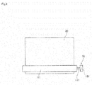
Figs. 9 and10 are side views showing the configurations of the suction roller, the separation roller and a rotation speed controller. - A preferred embodiment according to the present invention will now be described with reference to the drawings.
-
Fig. 1 is a diagram showing the configuration of amanufacturing apparatus 1 for a catalyst-coated membrane according to one preferred embodiment of the present invention. Thismanufacturing apparatus 1 is an apparatus that forms a catalyst layer serving as an electrode on a surface of an electrolyte membrane which is a strip-shaped thin film to manufacture a catalyst-coated membrane for a polymer electrolyte fuel cell. As shown inFig. 1 , themanufacturing apparatus 1 for a catalyst-coated membrane according to the present preferred embodiment includes an introduction andseparation part 10, asuction roller 20, acatalyst supply part 30, adrying furnace 40, an affixingpart 50, asurface cooling part 60, and acontroller 70. - The introduction and
separation part 10 introduces anelongated strip 90 comprised of two layers of abase material 91 and anelectrolyte membrane 92 onto an outer peripheral surface of thesuction roller 20, and separates thebase material 91 from theelectrolyte membrane 92. - For example, fluorine-based or hydrocarbon-based polymer electrolyte membranes are used as the
electrolyte membrane 92. Specific examples of theelectrolyte membrane 92 used herein include polymer electrolyte membranes containing perfluorocarbon sulfonic acid (e.g., Nafion® available from DuPont, USA; Flemion® available from Asahi Glass Co., Ltd.; Aciplex® available from Asahi Kasei Corporation; and Goreselect® available from W. L. Gore & Associates, Inc.). Theelectrolyte membrane 92 has a thickness in the range of 5 to 30 µm, for example. Theelectrolyte membrane 92 swells when exposed to moisture in the atmosphere, and shrinks when the humidity of the atmosphere is decreased. That is, theelectrolyte membrane 92 has the property of being easily deformable depending on the humidity of the atmosphere. - The
base material 91 is a back sheet for suppressing the deformation of theelectrolyte membrane 92. Resins having a mechanical strength higher than that of theelectrolyte membrane 92 and excellent in shape retaining function are used as the material of thebase material 91. Specific examples of thebase material 91 used herein include films made of PEN (polyethylene naphthalate) and PET (polyethylene terephthalate). Thebase material 91 has a thickness in the range of 25 to 100 µm, for example. - As shown in
Fig. 1 , the introduction andseparation part 10 includes aseparation roller 11, anintroduction part 12, adischarge part 13, and agas supply part 14. - The
separation roller 11 rotates about a horizontally extending axis. Theseparation roller 11 has a cylindrical outer peripheral surface of an elastic body. The outer peripheral surface of theseparation roller 11 and the outer peripheral surface of thesuction roller 20 to be described later are opposed to each other, with a gap therebetween through which theelongated strip 90 passes. Theseparation roller 11 is pressurized toward thesuction roller 20 by an air cylinder not shown. - The
introduction part 12 includes amembrane unwinding roller 121 and afirst detection roller 122. Both themembrane unwinding roller 121 and thefirst detection roller 122 are disposed parallel to theseparation roller 11. Before being supplied, theelongated strip 90 is wound on themembrane unwinding roller 121. Themembrane unwinding roller 121 is rotated by the power of a motor not shown. As themembrane unwinding roller 121 rotates, theelongated strip 90 is unwound from themembrane unwinding roller 121. - The
elongated strip 90 unwound from themembrane unwinding roller 121 is turned around by contacting the outer peripheral surface of thefirst detection roller 122, and is transported toward theseparation roller 11. Thefirst detection roller 122 detects the tension applied to theelongated strip 90 in theintroduction part 12 by measuring the load received from theelongated strip 90 by means of a load cell. Thecontroller 70 to be described later controls the number of rotations of themembrane unwinding roller 121 so that the tension of theelongated strip 90 detected by thefirst detection roller 122 is equal to a previously set value. -
Fig. 2 is an enlarged view of theseparation roller 11 and its surroundings. As shown inFig. 2 , theelongated strip 90 having passed over thefirst detection roller 122 is introduced into agap 15 defined between theseparation roller 11 and thesuction roller 20. At this time, thebase material 91 comes in contact with the outer peripheral surface of theseparation roller 11, and theelectrolyte membrane 92 comes in contact with the outer peripheral surface of thesuction roller 20. Theelongated strip 90 is pressed against the outer peripheral surface of thesuction roller 20 by the pressure received from theseparation roller 11. Then, theelectrolyte membrane 92 is suctioned onto the outer peripheral surface of thesuction roller 20 by the negative pressure (to be described later) of thesuction roller 20. - In the present preferred embodiment, a layer of
catalyst material 9a is previously formed on one of the surfaces of theelectrolyte membrane 92 unwound from themembrane unwinding roller 121. Thus, theelectrolyte membrane 92 together with the layer ofcatalyst material 9a is suctioned onto the outer peripheral surface of thesuction roller 20. The layer ofcatalyst material 9a is formed in a coating apparatus different from themanufacturing apparatus 1 by intermittently applying a catalyst ink to a surface of theelectrolyte membrane 92 while transporting theelongated strip 90 comprised of the two layers of thebase material 91 and theelectrolyte membrane 92 by a roll-to-roll process and then drying the applied catalyst ink. - The
discharge part 13 includes a basematerial winding roller 131 and asecond detection roller 132. Both the basematerial winding roller 131 and thesecond detection roller 132 are disposed parallel to theseparation roller 11. Thebase material 91 having passed through thegap 15 is transported away from thesuction roller 20 toward thesecond detection roller 132. Thus, thebase material 91 is separated from theelectrolyte membrane 92. The separatedbase material 91 is turned around by contacting the outer peripheral surface of thesecond detection roller 132, and is transported toward the basematerial winding roller 131. - The base
material winding roller 131 is rotated by the power of a motor not shown. Thus, thebase material 91 is wound on the basematerial winding roller 131. Thesecond detection roller 132 detects the tension applied to thebase material 91 in thedischarge part 13 by measuring the load received from thebase material 91 by means of a load cell. Thecontroller 70 to be described later controls the number of rotations of the basematerial winding roller 131 so that the tension of thebase material 91 detected by thesecond detection roller 132 is equal to a previously set value. - The
gas supply part 14 blows a gas onto the outside surface of theelectrolyte membrane 92 having passed through thegap 15 and held on thesuction roller 20 under suction. This promotes the separation of thebase material 91 from theelectrolyte membrane 92 and suppresses the lift of theelectrolyte membrane 92 from thesuction roller 20. The details on the configuration of thegas supply part 14 will be described later. - The
suction roller 20 is a roller that rotates while holding theelectrolyte membrane 92 on the outer peripheral surface thereof under suction. Thesuction roller 20 has the cylindrical outer peripheral surface greater in diameter than theseparation roller 11. Thesuction roller 20 has a diameter in the range of 400 to 1600 mm, for example. Thesuction roller 20 is rotated about an axis extending horizontally (i.e., parallel to the separation roller 11) by the power of a motor not shown. A first direction that is the direction of rotation of thesuction roller 20 is opposite from a second direction that is the direction of rotation of theseparation roller 11. - Examples of the material of the
suction roller 20 used herein include porous materials such as porous carbon and porous ceramics. Specific examples of the porous ceramics include sintered bodies of alumina (Al2O3) and silicon carbide (SiC). Theporous suction roller 20 has pores with a diameter of not greater than 5 µm, for example, and a porosity in the range of 15% to 50%, for example. The outer peripheral surface of thesuction roller 20 has a surface roughness of not greater than 5 µm in terms of Rz (maximum height), for example. Variations in the distance from the axis of rotation of thesuction roller 20 to the outer peripheral surface thereof during rotation are not greater than 10 µm. - The
suction roller 20 has an end surface provided with a suckingport 21. The suckingport 21 is connected to a sucking mechanism (e.g., an exhaust pump) not shown. When the sucking mechanism is brought into operation, a negative pressure (vacuum) is developed in the suckingport 21 of thesuction roller 20. Then, a negative pressure (vacuum) is developed also at the outer peripheral surface of thesuction roller 20 through the pores in thesuction roller 20. For example, a negative pressure of not less than 10 kPa is developed at the outer peripheral surface of thesuction roller 20 by developing a negative pressure of not less than 90 kPa in the suckingport 21. Theelectrolyte membrane 92 is transported in the form of an arc by the rotation of thesuction roller 20 while being held on the outer peripheral surface of thesuction roller 20 under suction by the negative pressure. - A plurality of water-cooled
tubes 22 are provided inside thesuction roller 20, as indicated by broken lines inFig. 1 . Cooling water temperature-controlled at a predetermined temperature is supplied from a water supply mechanism not shown to the water-cooledtubes 22. When themanufacturing apparatus 1 is in operation, the heat of thesuction roller 20 is absorbed by the cooling water serving as a heat medium. Thus, thesuction roller 20 is cooled. After absorbing the heat, the cooling water is discharged to a drainage mechanism not shown. - The
catalyst supply part 30 is a mechanism for applying a catalyst ink onto a surface of theelectrolyte membrane 92 transported by thesuction roller 20. An electrode paste obtained by dispersing particles containing a catalyst material (e.g., platinum (Pt)) in a solvent such as alcohol is used for the catalyst ink. As shown inFig. 1 , thecatalyst supply part 30 includes a coating nozzle 31. The coating nozzle 31 is provided downstream of theseparation roller 11 as seen in a direction (transport direction) in which theelectrolyte membrane 92 is transported by thesuction roller 20. The coating nozzle 31 has anejection orifice 311 opposed to the outer peripheral surface of thesuction roller 20. Theejection orifice 311 is a slit-shaped opening extending horizontally along the outer peripheral surface of thesuction roller 20. - A flow passage connection is established between the coating nozzle 31 and a catalyst
ink supply source 33 through asupply pipe 32. An on-offvalve 34 is interposed in the path of thesupply pipe 32. Thus, when the on-offvalve 34 is opened, the catalyst ink is supplied from the catalystink supply source 33 through thesupply pipe 32 to the coating nozzle 31. Then, the catalyst ink is ejected from theejection orifice 311 of the coating nozzle 31 toward theelectrolyte membrane 92. As a result, the outside surface of theelectrolyte membrane 92 held by thesuction roller 20 is coated with the catalyst ink. - In the present preferred embodiment, the catalyst ink is intermittently ejected from the
ejection orifice 311 of the coating nozzle 31 by opening and closing the on-offvalve 34 at fixed intervals. This causes the catalyst ink to be intermittently applied to the surface of theelectrolyte membrane 92 at fixed intervals in the transport direction. However, the catalyst ink may be continuously applied to the surface of theelectrolyte membrane 92 in the transport direction by continuously opening the on-offvalve 34. - A material that causes a fuel cell reaction to occur in the anode or cathode of a polymer fuel cell is used as the catalyst material in the catalyst ink. Specifically, platinum (Pt), a platinum alloy, a platinum compound and the like may be used as the catalyst material. Examples of the platinum alloy used herein include alloys of platinum and at least one metal selected from the group consisting of ruthenium (Ru), palladium (Pd), nickel (Ni), molybdenum (Mo), iridium (Ir), iron (Fe) and the like. In general, platinum is used as the catalyst material for the cathode, and any one of the platinum alloys is used as the catalyst material for the anode. The catalyst ink ejected from the coating nozzle 31 may be for the cathode or for the anode. The
catalyst materials electrolyte membrane 92 are catalyst materials of polarities opposite from each other. - The drying
furnace 40 is a section for drying the catalyst ink applied to the surface of theelectrolyte membrane 92. The dryingfurnace 40 according to the present preferred embodiment is disposed downstream of thecatalyst supply part 30 as seen in the direction (transport direction) in which theelectrolyte membrane 92 is transported by thesuction roller 20. The dryingfurnace 40 is provided in the form of an arc along the outer peripheral surface of thesuction roller 20. As shown inFig. 1 , the dryingfurnace 40 includes three hotgas supply parts 41 to 43, and twoheat insulation parts gas supply parts 41 to 43 blow heated gases (hot gases) toward the outer peripheral surface of thesuction roller 20. When theelectrolyte membrane 92 coated with the catalyst ink passes along the hotgas supply parts 41 to 43, the catalyst ink is dried to solidify by the hot gases. That is, the solvent in the catalyst ink is evaporated, so that the layer ofcatalyst material 9b is formed on the surface of theelectrolyte membrane 92. - The three hot
gas supply parts 41 to 43 blow the hot gases at different temperatures. The temperatures of the hot gases blown from the three hotgas supply parts 41 to 43 are in ascending order from upstream to downstream as seen in the direction (transport direction) in which theelectrolyte membrane 92 is transported by thesuction roller 20. The temperature of the hot gas blown from the hotgas supply part 41 most upstream as seen in the transport direction is, for example, in the range from an ambient environmental temperature to 40°C. The temperature of the hot gas blown from the next hotgas supply part 42 is, for example, in the range from 40°C to 80°C. The temperature of the hot gas blown from the hotgas supply part 43 most downstream as seen in the transport direction is, for example, in the range from 50°C to 100°C. - In this manner, the temperatures of the hot gases blown onto the
electrolyte membrane 92 in the dryingfurnace 40 according to the present preferred embodiment are in ascending order toward downstream as seen in the transport direction. This allows a less steep increase in the temperatures of theelectrolyte membrane 92 and the catalyst ink to thereby suppress the occurrence of damages to thecatalyst material 9b such as cracks in thecatalyst material 9b due to abrupt drying. - The two
heat insulation parts gas supply parts 41 to 43 as seen in the direction (transport direction) in which theelectrolyte membrane 92 is transported by thesuction roller 20. Specifically, theheat insulation part 44 is disposed upstream of the hotgas supply part 41 most upstream as seen in the transport direction, and theheat insulation part 45 is disposed downstream of the hotgas supply part 43 most downstream as seen in the transport direction. Theseheat insulation parts suction roller 20. This prevents the hot gases blown from the hotgas supply parts 41 to 43 from flowing upstream and downstream as seen in the transport direction beyond theheat insulation parts heat insulation parts heat insulation parts -
Fig. 3 is a schematic view showing the shape of the dryingfurnace 40 taken along a section including the axis of thesuction roller 20. As shown inFig. 3 , the dryingfurnace 40 according to the present preferred embodiment includes a pair of suckingparts parts gas supply parts 41 to 43 toward thesuction roller 20. The suckingparts suction roller 20. These suckingparts gas supply parts 41 to 43 and the vapor of the solvent from flowing outwardly beyond the suckingparts - The affixing
part 50 affixes a strip-shapedsupport film 93 to the surface of theelectrolyte membrane 92 with the layer ofcatalyst material 9b formed thereon. The affixingpart 50 is disposed downstream of the dryingfurnace 40 as seen in the direction (transport direction) in which theelectrolyte membrane 92 is transported by thesuction roller 20. As shown inFig. 1 , the affixingpart 50 includes alaminating roller 51, afilm supply part 52, and a catalyst-coatedmembrane collection part 53. -
Fig. 4 is an enlarged view of the laminatingroller 51 and its surroundings. The laminatingroller 51 is a roller that rotates about a horizontally extending axis. The laminatingroller 51 has a cylindrical outer peripheral surface smaller in diameter than thesuction roller 20. The outer peripheral surface of the laminatingroller 51 and the outer peripheral surface of thesuction roller 20 are opposed to each other, with a gap therebetween through which theelectrolyte membrane 92 and thesupport film 93 pass. The laminatingroller 51 is pressurized toward thesuction roller 20 by an air cylinder not shown. - A metal having a high thermal conductivity, for example, is used as the material of the laminating
roller 51. Aheater 511 that generates heat when energized is provided inside the laminatingroller 51. A sheathed heater, for example, may be used as theheater 511. When theheater 511 is energized, the outer peripheral surface of the laminatingroller 51 is temperature-controlled at a predetermined temperature higher than the environmental temperature by the heat generated from theheater 511. An output from theheater 511 may be controlled so that the temperature of the outer peripheral surface of the laminatingroller 51 measured using a temperature sensor such as a radiation thermometer reaches a fixed temperature based on the result of measurement. - Referring again to
Fig. 1 , thefilm supply part 52 includes afilm unwinding roller 521 and athird detection roller 522. Both thefilm unwinding roller 521 and thethird detection roller 522 are disposed parallel to thelaminating roller 51. Before being supplied, thesupport film 93 is wound on thefilm unwinding roller 521. Thefilm unwinding roller 521 is rotated by the power of a motor not shown. Thesupport film 93 is unwound from thefilm unwinding roller 521 by the rotation of thefilm unwinding roller 521. - Resins having a mechanical strength higher than that of the
electrolyte membrane 92 and excellent in shape retaining function are used as the material of thesupport film 93. Specific examples of thesupport film 93 used herein include films made of PEN (polyethylene naphthalate) and PET (polyethylene terephthalate). Thesupport film 93 may be the same as thebase material 91. Also, thebase material 91 wound on the basematerial winding roller 131 may be unwound as thesupport film 93 from thefilm unwinding roller 521. - The unwound
support film 93 is turned around by contacting the outer peripheral surface of thethird detection roller 522, and is transported toward the laminatingroller 51. Thethird detection roller 522 detects the tension applied to thesupport film 93 in thefilm supply part 52 by measuring the load received from thesupport film 93 by means of a load cell. Thecontroller 70 to be described later controls the number of rotations of thefilm unwinding roller 521 so that the tension of thesupport film 93 detected by thethird detection roller 522 is equal to a previously set value. - The
support film 93 having passed over thethird detection roller 522 is introduced in between theelectrolyte membrane 92 held on the outer peripheral surface of thesuction roller 20 under suction and thelaminating roller 51. At this time, thesupport film 93 is pressed against theelectrolyte membrane 92 by the pressure received from the laminatingroller 51, and is heated by the heat of the laminatingroller 51. As a result, thesupport film 93 is affixed to the outside surface of theelectrolyte membrane 92. Thecatalyst material 9b formed on the surface of theelectrolyte membrane 92 is sandwiched between theelectrolyte membrane 92 and thesupport film 93. This provides a catalyst-coatedmembrane 94 including theelectrolyte membrane 92, thecatalyst materials support film 93. - The catalyst-coated
membrane collection part 53 includes a catalyst-coatedmembrane winding roller 531 and afourth detection roller 532. Both the catalyst-coatedmembrane winding roller 531 and thefourth detection roller 532 are disposed parallel to thelaminating roller 51. The catalyst-coatedmembrane 94 having passed between thesuction roller 20 and thelaminating roller 51 is transported away from thesuction roller 20 toward thefourth detection roller 532. Then, the catalyst-coatedmembrane 94 is turned around by contacting the outer peripheral surface of thefourth detection roller 532, and is transported toward the catalyst-coatedmembrane winding roller 531. - The catalyst-coated
membrane winding roller 531 is rotated by the power of a motor not shown. Thus, the catalyst-coatedmembrane 94 is wound on the catalyst-coatedmembrane winding roller 531. Thefourth detection roller 532 detects the tension applied to the catalyst-coatedmembrane 94 in the catalyst-coatedmembrane collection part 53 by measuring the load received from the catalyst-coatedmembrane 94 by means of a load cell. Thecontroller 70 to be described later controls the number of rotations of the catalyst-coatedmembrane winding roller 531 so that the tension of the catalyst-coatedmembrane 94 detected by thefourth detection roller 532 is equal to a previously set value. - The
surface cooling part 60 is a mechanism for cooling the outer peripheral surface of thesuction roller 20. Thesurface cooling part 60 is disposed at a position opposed to a region of the outer peripheral surface of thesuction roller 20 which lies between the affixingpart 50 and the introduction andseparation part 10 and which does not hold theelectrolyte membrane 92 thereon. Thesurface cooling part 60 blows clean dry air at a temperature (e.g., approximately 5°C) lower than the environmental temperature, for example, onto the outer peripheral surface of thesuction roller 20. Thesuction roller 20 heated by the dryingfurnace 40 and thelaminating roller 51 is cooled by being exposed to the clean dry air. - In this manner, the steps of unwinding the
elongated strip 90 from themembrane unwinding roller 121, separating thebase material 91 from theelectrolyte membrane 92, applying the catalyst ink to theelectrolyte membrane 92, drying by means of the dryingfurnace 40, and affixing thesupport film 93 to theelectrolyte membrane 92 are performed sequentially in themanufacturing apparatus 1 according to the present preferred embodiment. This manufactures the catalyst-coatedmembrane 94 used for the electrodes of the polymer electrolyte fuel cell. Theelectrolyte membrane 92 is always held by any one of thebase material 91, thesuction roller 20 and thesupport film 93. This suppresses the deformation, such as swelling and shrinking, of theelectrolyte membrane 92 in themanufacturing apparatus 1. - The
controller 70 is a part for controlling the operations of the components in themanufacturing apparatus 1.Fig. 5 is a block diagram showing connections between thecontroller 70 and the components in themanufacturing apparatus 1. As conceptually shown inFig. 5 , thecontroller 70 includes a computer having anarithmetic processor 71 such as a CPU, amemory 72 such as a RAM, and astorage part 73 such as a hard disk drive. A computer program P for executing a printing process is installed in thestorage part 73. - As shown in
Fig. 5 , thecontroller 70 is connected to the motor of the aforementionedmembrane unwinding roller 121, the load cell of thefirst detection roller 122, the motor of the basematerial winding roller 131, the load cell of thesecond detection roller 132, the motor of thesuction roller 20, the sucking mechanism of thesuction roller 20, the water supply mechanism of thesuction roller 20, the on-offvalve 34, the three hotgas supply parts 41 to 43, the twoheat insulation parts parts heater 511, the motor of thefilm unwinding roller 521, the load cell of thethird detection roller 522, the motor of the catalyst-coatedmembrane winding roller 531, the load cell of thefourth detection roller 532, and thesurface cooling part 60 for communication therewith. Thecontroller 70 is also connected to an on-offvalve 85 to be described later for communication therewith. - The
controller 70 temporarily reads the computer program P and data that are stored in thestorage part 73 onto thememory 72, and thearithmetic processor 71 performs arithmetic processing based on the computer program P, so that thecontroller 70 controls the operations of the aforementioned components. Thus, the process of manufacturing a catalyst-coated membrane in themanufacturing apparatus 1 proceeds. - Next, description will be given on a configuration for suppressing the lift of the
electrolyte membrane 92 from thesuction roller 20 during the separation of thebase material 91 from theelectrolyte membrane 92. -
Fig. 6 is a perspective view of theseparation roller 11, thegas supply part 14, and thesuction roller 20. As shown inFig. 6 , thegas supply part 14 according to the present preferred embodiment includes a plurality ofpipe nozzles 81 each having a tubular member that ejects a gas from the tip thereof. The pipe nozzles 81 are spaced substantially equidistantly in the width direction of the electrolyte membrane 92 (a direction orthogonal to the transport direction of the electrolyte membrane and parallel to the front and back surfaces of the electrolyte membrane). Each of thepipe nozzles 81 has an ejection orifice directed toward the front surface of theelectrolyte membrane 92. As shown inFig. 1 , anangle 0 between the location of thepipe nozzles 81 and the location of the coating nozzle 31 about the axis of thesuction roller 20 is not greater than 90 degrees. - As conceptually shown in
Fig. 6 , flow passage connections are established between thepipe nozzles 81 and first ends ofgas supply pipes 82, respectively. Flow passage connections are established between second ends of thegas supply pipes 82 and a first end of a singlemain pipe 83. A flow passage connection is established between a second end of themain pipe 83 and agas supply source 84. Thegas supply source 84 is filled with a gas at a pressure higher than atmospheric pressure. The on-offvalve 85 is interposed in the path of themain pipe 83. - Thus, when the on-off
valve 85 is opened, the gas is supplied from thegas supply source 84 through themain pipe 83 and thegas supply pipes 82 to thepipe nozzles 81. Then, the gas is ejected from the ejection orifices of therespective pipe nozzles 81 toward the front surface of theelectrolyte membrane 92. For example, clean dry air may be used as the gas ejected from thepipe nozzles 81. A clean dry inert gas such as nitrogen gas may be used in place of the clean dry air. An electrical discharging air such as ionized gas to control static electricity charged on theelectrolyte membrane 92 may be used in place of the clean dry air. -
Fig. 7 is a flow diagram showing a procedure between the introduction of theelongated strip 90 and the supply of the catalyst ink. In thismanufacturing apparatus 1, theelongated strip 90 unwound from themembrane unwinding roller 121 is initially introduced into thegap 15 defined between thesuction roller 20 and the separation roller 11 (Step S1), as stated above. After passing through thegap 15, theelectrolyte membrane 92 is held on the outer peripheral surface of thesuction roller 20 under suction. After passing through thegap 15, thebase material 91 is transported away from the outer peripheral surface of thesuction roller 20. Thus, thebase material 91 is separated from the electrolyte membrane 92 (Step S2). At this time, thegas supply part 14 blows the gas toward theelectrolyte membrane 92 immediately after the separation (Step S3). This suppresses the lift of theelectrolyte membrane 92 from the outer peripheral surface of thesuction roller 20. Thereafter, the catalyst ink is supplied from the coating nozzle 31 onto the outside surface of theelectrolyte membrane 92 held on thesuction roller 20 under suction (Step S4). -
Fig. 8 is a view showing a widthwise positional relationship between theelectrolyte membrane 92 held on thesuction roller 20 and thepipe nozzles 81. As shown inFig. 8 , thepipe nozzles 81 blow the gas toward respective ejection regions A arranged in the width direction of theelectrolyte membrane 92. Two of thepipe nozzles 81 disposed at opposite outermost positions as seen in the width direction blow the gas toward two (referred to hereinafter as "first ejection regions A1") of the ejection regions A positioned on opposite edges of theelectrolyte membrane 92 as seen in the width direction. The remainingpipe nozzles 81 blow the gas toward the remaining ejection regions A (referred to hereinafter as "second ejection regions A2") positioned between the two first ejection regions A1. Theelectrolyte membrane 92 is pressed against the outer peripheral surface of thesuction roller 20 by blowing the gas onto theelectrolyte membrane 92 in this manner. This promotes the separation of thebase material 91 from theelectrolyte membrane 92 and suppresses the lift of theelectrolyte membrane 92 together with thebase material 91 from the outer peripheral surface of thesuction roller 20. - In particular, parts of the outer peripheral surface of the
suction roller 20 which come in contact with the opposite edges of theelectrolyte membrane 92 as seen in the width direction are less prone to decrease in the pressure of the suckingport 21 because these parts are adjacent to parts thereof which are exposed to outside air without contacting theelectrolyte membrane 92. For this reason, the force of suction caused by the suckingport 21 is poor near the opposite edges of theelectrolyte membrane 92 as seen in the width direction. To solve such a problem, thegas supply part 14 blows the gas toward the pair of first ejection regions A1 positioned on the opposite edges of theelectrolyte membrane 92 as seen in the width direction, as shown inFig. 8 . This suppresses the lift of the opposite edges of theelectrolyte membrane 92 as seen in the width direction from the outer peripheral surface of thesuction roller 20. - It is only necessary that the
gas supply part 14 blows the gas toward at least the pair of first ejection regions A1 where the force of suction is poor. However, the lift of theelectrolyte membrane 92 from thesuction roller 20 is further suppressed by blowing the gas not only toward the first ejection regions A1 but also toward the second ejection regions A2 positioned inside the first ejection regions A1 as in the present preferred embodiment. The number of second ejection regions A2 may be either one or not less than one. - The
gas supply part 14 does not uniformly blow the gas across the width of theelectrolyte membrane 92 but blows the gas toward the ejection regions A discontinuous in the width direction. The gas blown onto the ejection regions A flows between adjacent ones of thepipe nozzles 81 away from thesuction roller 20, as indicated by broken arrows inFig. 8 . This reduces the amount of gas flowing toward the coating nozzle 31, to thereby suppress the disturbance of the catalyst ink ejected from the coating nozzle 31 and the unintended drying of the catalyst ink due to the influence of thegas supply part 14. As a result, the occurrence of coating failures resulting from thegas supply part 14 is suppressed. - In particular, the
pipe nozzles 81 and the coating nozzle 31 are disposed close to each other in themanufacturing apparatus 1. Specifically, the angle θ (angle of rotation of theelectrolyte membrane 92 from Step S3 to Step S4) between the location of thepipe nozzles 81 and the location of the coating nozzle 31 about the axis of thesuction roller 20 is not greater than 90 degrees. The gas blown from thegas supply part 14 is prone to flow toward the coating nozzle 31 because of such a positional relationship. It is hence especially important to ensure the flow passage of the gas ejected from thepipe nozzles 81 away from thesuction roller 20, thereby suppressing the influence upon the coating nozzle 31. - Also, the
pipe nozzles 81 according to the present preferred embodiment are disposed obliquely with respect to the radial direction of thesuction roller 20, as shown inFig. 2 . The gas is ejected from thepipe nozzles 81 toward the gap 15 (away from the coating nozzle 31). This further reduces the amount of gas flowing toward the coating nozzle 31. As a result, the occurrence of coating failures resulting from thegas supply part 14 is further suppressed. - The
manufacturing apparatus 1 further includes arotation speed controller 16 that controls a relationship between the rotation speed of thesuction roller 20 and the rotation speed of theseparation roller 11.Fig. 9 is a side view showing the configurations of thesuction roller 20, theseparation roller 11, and therotation speed controller 16. - The
separation roller 11 according to the present preferred embodiment is not directly connected to a driving source such as a motor, but is a free roller that does not spontaneously rotate. As mentioned above, theseparation roller 11 is pressurized toward thesuction roller 20 by the air cylinder not shown. Thus, as thesuction roller 20 rotates, theseparation roller 11 is driven to rotate by the force received through theelongated strip 90. Abraking part 161 serving as therotation speed controller 16 is provided at an end of therotary shaft 11 of theseparation roller 11. An example of thebraking part 161 used herein includes a powder clutch that generates a braking force through the use of the friction of powder. - When the
separation roller 11 is rotated, thebraking part 161 produces a resisting force in a direction opposing the rotation of theseparation roller 11. This provides a load to the rotation of theseparation roller 11. As a result, the moving speed (indicated by an arrow v2 inFig. 2 ) of the outer peripheral surface of theseparation roller 11 in thegap 15 is slightly lower than the moving speed (indicated by an arrow v1 inFig. 2 ) of the outer peripheral surface of thesuction roller 20 in thegap 15. In this manner, the decrease in the rotation speed of theseparation roller 11 weakens the force with which thebase material 91 in contact with theseparation roller 11 attracts theelectrolyte membrane 92 toward theseparation roller 11. Thus, the separation of thebase material 91 from theelectrolyte membrane 92 is promoted. As a result, the lift of theelectrolyte membrane 92 from the outer peripheral surface of thesuction roller 20 is further suppressed. - When the outer peripheral surface of the
separation roller 11 and thebase material 91 are not movable relative to each other, the transport speed of thebase material 91 is lower than the transport speed of theelectrolyte membrane 92. At this time, there is a danger that an excessive tension is applied to theelectrolyte membrane 92 to damage theelectrolyte membrane 92. It is hence preferable that theseparation roller 11 is rotated slidably relative to thebase material 91. - The
separation roller 11 may be spontaneously rotated while the speed of rotation of theseparation roller 11 is controlled. For example, as shown inFig. 10 , aservomotor 162 serving as therotation speed controller 16 may be connected to an end of therotary shaft 111 of theseparation roller 11. Theservomotor 162 is connected to theaforementioned controller 70, and is a motor whose RPM (the number of revolutions) is controllable based on a control signal supplied from thecontroller 70. In the configuration shown inFig. 10 , thecontroller 70 controls the RPM of theservomotor 162 so that the moving speed of the outer peripheral surface of theseparation roller 11 in thegap 15 is slightly lower than the moving speed of the outer peripheral surface of thesuction roller 20 in thegap 15. This promotes the separation of thebase material 91 from theelectrolyte membrane 92 to suppress the lift of theelectrolyte membrane 92 from thesuction roller 20. - As described above, the
controller 70 controls the number of rotations of themembrane unwinding roller 121 so that the tension of theelongated strip 90 detected by thefirst detection roller 122 is equal to a previously set value (referred to hereinafter as a "first set value"). Thus, the tension of theelongated strip 90 in theintroduction part 12 is maintained at the first set value that is fixed. Thecontroller 70 also controls the number of rotations of the basematerial winding roller 131 so that the tension of thebase material 91 detected by thesecond detection roller 132 is equal to a previously set value (referred to hereinafter as a "second set value"). Thus, the tension of thebase material 91 in thedischarge part 13 is maintained at the second set value that is fixed. - In other words, the
membrane unwinding roller 121, thefirst detection roller 122, the basematerial winding roller 131, and thesecond detection roller 132 in the present preferred embodiment constitute a tension controller that controls a relationship between the tension of theelongated strip 90 in theintroduction part 12 and the tension of thebase material 91 in thedischarge part 13. - In the
manufacturing apparatus 1 according to the present preferred embodiment, the aforementioned second set value is lower than the aforementioned first set value. Thus, the control of the number of rotations of themembrane unwinding roller 121 and the number of rotations of the basematerial winding roller 131 causes the tension of thebase material 91 in thedischarge part 13 to be lower than the tension of theelongated strip 90 in theintroduction part 12. The force with which thebase material 91 attracts theelectrolyte membrane 92 is weakened by making the tension of thebase material 91 after the separation lower than the tension of theelongated strip 90 introduced into thegap 15. Thus, the separation of thebase material 91 from theelectrolyte membrane 92 is promoted. As a result, the lift of theelectrolyte membrane 92 from the outer peripheral surface of thesuction roller 20 is further suppressed. - While the one preferred embodiment according to the present invention has been described hereinabove, the present invention is not limited to the aforementioned preferred embodiment.
- In the aforementioned preferred embodiment, the
pipe nozzles 81 are used in thegas supply part 14. However, thegas supply part 14 may include nozzles other than the pipe nozzles. For example, a plurality of nozzles having ejection orifices in the form of slits extending in the transport direction of theelectrolyte membrane 92 may be arranged in the width direction of theelectrolyte membrane 92. - In the aforementioned preferred embodiment, the angle θ (with reference to
Fig. 1 ) between the location of thepipe nozzles 81 and the location of the coating nozzle 31 about the axis of thesuction roller 20 is not greater than 90 degrees. However, the angle θ between the location of thepipe nozzles 81 and the location of the coating nozzle 31 may be greater than 90 degrees. The increase in the angle 8 between the location of thepipe nozzles 81 and the location of the coating nozzle 31 makes the gas ejected from thepipe nozzles 81 less prone to reach the coating nozzle 31. This further suppresses the disturbance of the catalyst ink ejected from the coating nozzle 31 and the unintended drying of the catalyst ink due to the influence of thegas supply part 14. - In the aforementioned preferred embodiment, the
catalyst material 9b is formed on one of the surfaces of theelectrolyte membrane 92 with the layer ofcatalyst material 9a previously formed on the other surface thereof. However, the manufacturing apparatus according to the present invention may be configured to form the catalyst material on the electrolyte membrane with the layer ofcatalyst material 9a not formed on the opposite surfaces thereof. - The configuration of the details of the manufacturing apparatus may differ from that shown in the figures of the present invention. The components described in the aforementioned preferred embodiment and in the modifications may be combined together, as appropriate, without inconsistencies.
- While the invention has been described in detail, the foregoing description is in all aspects illustrative and not restrictive. It is understood that numerous other modifications and variations can be devised without departing from the scope of the invention.
Claims (18)
- An apparatus for manufacturing a catalyst-coated membrane, the apparatus separating an electrolyte membrane from an elongated strip comprised of at least two layers of a base material and the electrolyte membrane to form a catalyst layer on a surface of the separated electrolyte membrane, the apparatus comprising:a suction roller having an outer peripheral surface and rotating in a first direction about its axis while holding said electrolyte membrane on the outer peripheral surface under suction;an introduction and separation part for introducing said elongated strip with said base material positioned outside onto the outer peripheral surface of said suction roller, and for separating said base material from said electrolyte membrane; anda catalyst supply part for supplying a catalyst material to the outside surface of said electrolyte membrane held on said suction roller under suction,said introduction and separation part including
a separation roller opposed to said suction roller, with a gap therebetween through which said elongated strip passes, said separation roller rotating in a second direction different from said first direction about an axis parallel to said suction roller,
an introduction part for introducing said elongated strip toward said gap,
a discharge part for transporting said base material having passed through said gap away from the outer peripheral surface of said suction roller, and
a gas supply part for blowing a gas onto the outside surface of said electrolyte membrane having passed through said gap and held on said suction roller under suction,
said gas supply part blowing the gas toward a plurality of ejection regions discontinuous in the width direction of said electrolyte membrane and including at least opposite edges of said electrolyte membrane as seen in the width direction of said electrolyte membrane. - The apparatus according to claim 1, wherein
said ejection regions include
the opposite edges of said electrolyte membrane as seen in the width direction of said electrolyte membrane, and
at least one region positioned between said opposite edges. - The apparatus according to claim 1 or 2, wherein
an angle between said gas supply part and said catalyst supply part about said axis of said suction roller is not greater than 90 degrees. - The apparatus according to any one of claims 1 to 3, further comprising
a tension controller for controlling a relationship between the tension of said elongated strip in said introduction part and the tension of said base material in said discharge part. - The apparatus according to claim 4, wherein
said tension controller makes the tension of said base material in said discharge part lower than the tension of said elongated strip in said introduction part. - The apparatus according to any one of claims 1 to 5, further comprising
a rotation speed controller for controlling a relationship between the rotation speed of said suction roller and the rotation speed of said separation roller. - The apparatus according to claim 6, wherein
said rotation speed controller makes the moving speed of the outer peripheral surface of said separation roller in said gap lower than the moving speed of the outer peripheral surface of said suction roller in said gap. - The apparatus according to claim 7, wherein
said separation roller is driven to rotate as said suction roller rotates, and
said rotation speed controller includes a braking part for providing a load to the rotation of said separation roller. - The apparatus according to claim 7, wherein
said rotation speed controller includes a servomotor capable of controlling the number of rotations of said separation roller. - The apparatus according to any one of claims 7 to 9, wherein
said separation roller is rotated slidably relative to said base material. - A method of manufacturing a catalyst-coated membrane, the method separating an electrolyte membrane from an elongated strip comprised of at least two layers of a base material and the electrolyte membrane to form a catalyst layer on a surface of the separated electrolyte membrane, the method comprising the steps of:a) introducing said elongated strip into a gap defined between a suction roller and a separation roller disposed parallel to each other;b) holding said electrolyte membrane having passed through said gap on said suction roller under suction and transporting said base material having passed through said gap away from the outer peripheral surface of said suction roller to thereby separate said base material from said electrolyte membrane;c) blowing a gas onto the outside surface of said electrolyte membrane having passed through said gap and held on said suction roller under suction; andd) supplying a catalyst material to the outside surface of said electrolyte membrane held on said suction roller under suction,the gas being blown toward a plurality of ejection regions discontinuous in the width direction of said electrolyte membrane and including at least opposite edges of said electrolyte membrane as seen in the width direction of the electrolyte membrane in said step c).
- The method according to claim 11, wherein
said ejection regions include
the opposite edges of said electrolyte membrane as seen in the width direction of said electrolyte membrane, and
at least one region positioned between said opposite edges. - The method according to claim 11 or 12, wherein
an angle of rotation of said electrolyte membrane between said steps c) and d) is not greater than 90 degrees. - The method according to any one of claims 11 to 13, wherein
a relationship between the tension of said elongated strip introduced into said gap and the tension of said base material after the separation is controlled in said step b). - The method according to claim 14, wherein
the tension of said base material after the separation is made lower than the tension of said elongated strip introduced into said gap in said step b). - The method according to any one of claims 11 to 15, wherein
a relationship between the rotation speed of said suction roller and the rotation speed of said separation roller is controlled in said step b). - The method according to claim 16, wherein
the moving speed of the outer peripheral surface of said separation roller in said gap is made lower than the moving speed of the outer peripheral surface of said suction roller in said gap in said step b). - The method according to claim 17, wherein
said separation roller is rotated slidably relative to said base material in said step b).
Applications Claiming Priority (1)
| Application Number | Priority Date | Filing Date | Title |
|---|---|---|---|
| JP2015189124A JP6541531B2 (en) | 2015-09-28 | 2015-09-28 | Apparatus and method for manufacturing membrane / catalyst layer assembly |
Publications (2)
| Publication Number | Publication Date |
|---|---|
| EP3147977A1 true EP3147977A1 (en) | 2017-03-29 |
| EP3147977B1 EP3147977B1 (en) | 2026-01-14 |
Family
ID=56203272
Family Applications (1)
| Application Number | Title | Priority Date | Filing Date |
|---|---|---|---|
| EP16176136.6A Active EP3147977B1 (en) | 2015-09-28 | 2016-06-24 | Apparatus for and method of manufacturing catalyst-coated membrane |
Country Status (3)
| Country | Link |
|---|---|
| EP (1) | EP3147977B1 (en) |
| JP (1) | JP6541531B2 (en) |
| KR (1) | KR101884065B1 (en) |
Cited By (3)
| Publication number | Priority date | Publication date | Assignee | Title |
|---|---|---|---|---|
| EP3866243A4 (en) * | 2018-12-04 | 2022-01-26 | Lg Energy Solution, Ltd. | LAMINATING APPARATUS AND METHOD, AND SECONDARY BATTERY MANUFACTURING EQUIPMENT COMPRISING THEM |
| CN114243033A (en) * | 2021-12-09 | 2022-03-25 | 同济大学 | Flaw-free catalyst directly coated proton exchange membrane and preparation method and application thereof |
| DE102024201266A1 (en) | 2024-02-12 | 2025-08-14 | Robert Bosch Gesellschaft mit beschränkter Haftung | Method and device for producing a membrane unit for an electrochemical energy converter |
Families Citing this family (2)
| Publication number | Priority date | Publication date | Assignee | Title |
|---|---|---|---|---|
| KR20220066679A (en) | 2020-11-16 | 2022-05-24 | 현대자동차주식회사 | A membrane-electrode-subgasket assembly manufacturing apparatus and method for manufacturing membrane-electrode-subgasket assembly using the same |
| KR102563771B1 (en) * | 2021-03-16 | 2023-08-07 | (주)나노테크 | Heating roller for manufacturing secondary battery |
Citations (4)
| Publication number | Priority date | Publication date | Assignee | Title |
|---|---|---|---|---|
| US6692542B1 (en) * | 1999-11-26 | 2004-02-17 | Matsushita Electric Industrial Co., Ltd. | Apparatus for manufacturing spiral electrode assembly |
| JP2013182682A (en) | 2012-02-29 | 2013-09-12 | Toyota Motor Corp | Method and apparatus for manufacturing membrane electrode assembly |
| EP2813363A1 (en) * | 2013-05-20 | 2014-12-17 | Dainippon Screen Mfg. Co., Ltd. | Apparatus and method for manufacturing catalyst-coated membrane for a fuel cell |
| EP2903065A1 (en) * | 2012-09-28 | 2015-08-05 | Nissan Motor Co., Ltd. | Coating device |
Family Cites Families (4)
| Publication number | Priority date | Publication date | Assignee | Title |
|---|---|---|---|---|
| JP2012020870A (en) * | 2010-07-16 | 2012-02-02 | Fujifilm Corp | Image recording method and image recording device |
| KR20140078152A (en) * | 2012-12-17 | 2014-06-25 | (주)프로템 | Database based Servo motor control system for Roll to Roll Equipment |
| JP6085490B2 (en) * | 2013-02-06 | 2017-02-22 | リンテック株式会社 | Sheet sticking device and sheet sticking method |
| JP2015015258A (en) * | 2014-09-18 | 2015-01-22 | 株式会社Screenホールディングス | Membrane / electrode assembly manufacturing equipment |
-
2015
- 2015-09-28 JP JP2015189124A patent/JP6541531B2/en active Active
-
2016
- 2016-06-24 EP EP16176136.6A patent/EP3147977B1/en active Active
- 2016-07-18 KR KR1020160090559A patent/KR101884065B1/en active Active
Patent Citations (4)
| Publication number | Priority date | Publication date | Assignee | Title |
|---|---|---|---|---|
| US6692542B1 (en) * | 1999-11-26 | 2004-02-17 | Matsushita Electric Industrial Co., Ltd. | Apparatus for manufacturing spiral electrode assembly |
| JP2013182682A (en) | 2012-02-29 | 2013-09-12 | Toyota Motor Corp | Method and apparatus for manufacturing membrane electrode assembly |
| EP2903065A1 (en) * | 2012-09-28 | 2015-08-05 | Nissan Motor Co., Ltd. | Coating device |
| EP2813363A1 (en) * | 2013-05-20 | 2014-12-17 | Dainippon Screen Mfg. Co., Ltd. | Apparatus and method for manufacturing catalyst-coated membrane for a fuel cell |
Cited By (4)
| Publication number | Priority date | Publication date | Assignee | Title |
|---|---|---|---|---|
| EP3866243A4 (en) * | 2018-12-04 | 2022-01-26 | Lg Energy Solution, Ltd. | LAMINATING APPARATUS AND METHOD, AND SECONDARY BATTERY MANUFACTURING EQUIPMENT COMPRISING THEM |
| US12463303B2 (en) | 2018-12-04 | 2025-11-04 | Lg Energy Solution, Ltd. | Lamination device and method and secondary battery manufacturing equipment comprising lamination device |
| CN114243033A (en) * | 2021-12-09 | 2022-03-25 | 同济大学 | Flaw-free catalyst directly coated proton exchange membrane and preparation method and application thereof |
| DE102024201266A1 (en) | 2024-02-12 | 2025-08-14 | Robert Bosch Gesellschaft mit beschränkter Haftung | Method and device for producing a membrane unit for an electrochemical energy converter |
Also Published As
| Publication number | Publication date |
|---|---|
| JP6541531B2 (en) | 2019-07-10 |
| EP3147977B1 (en) | 2026-01-14 |
| KR101884065B1 (en) | 2018-07-31 |
| KR20170037813A (en) | 2017-04-05 |
| JP2017068899A (en) | 2017-04-06 |
Similar Documents
| Publication | Publication Date | Title |
|---|---|---|
| US10505200B2 (en) | Apparatus and method manufacturing composite membrane | |
| EP3208879B1 (en) | Apparatus for manufacturing membrane electrode assembly | |
| EP2903065B1 (en) | Method of using a coating device | |
| EP3147977B1 (en) | Apparatus for and method of manufacturing catalyst-coated membrane | |
| EP3050703A1 (en) | Drying apparatus and drying method | |
| JP6352730B2 (en) | Membrane / catalyst layer assembly manufacturing apparatus and manufacturing method | |
| JP6352727B2 (en) | Membrane / catalyst layer assembly manufacturing apparatus and manufacturing method | |
| JP2016046091A (en) | COATING APPARATUS AND COATING METHOD, AND Membrane / catalyst layer assembly manufacturing apparatus and manufacturing method | |
| EP3597310A1 (en) | Coating device and coating method | |
| US20180053946A1 (en) | Suction roller, coating apparatus and apparatus for manufacturing membrane electrode assembly | |
| KR102038763B1 (en) | Base material processing apparatus and base material processing method | |
| JP6527813B2 (en) | Coating apparatus, manufacturing apparatus and measuring method | |
| JP6669515B2 (en) | Apparatus and method for producing membrane / catalyst layer assembly | |
| EP3544102B1 (en) | Support film, affixing method, and method of and apparatus for manufacturing membrane electrode assembly | |
| KR101928623B1 (en) | Connecting method, coating method, manufacturing method, connecting appratus, coating apparatus, and manufacturing apparatus | |
| KR102038762B1 (en) | Coating apparatus and coating method | |
| JP6311041B2 (en) | Manufacturing method of membrane / catalyst layer assembly | |
| JP6751555B2 (en) | Manufacturing method and manufacturing equipment for membrane / catalyst layer joints | |
| JP6517402B2 (en) | Equipment for membrane / catalyst layer assembly | |
| JP6586336B2 (en) | Connection method, coating method, connection device and coating device | |
| JP2020017374A (en) | Backing material treatment device and backing material processing method | |
| JP2025119315A (en) | Connecting substrate, peeling method, coating method, peeling device, coating device, and substrate connecting method |
Legal Events
| Date | Code | Title | Description |
|---|---|---|---|
| PUAI | Public reference made under article 153(3) epc to a published international application that has entered the european phase |
Free format text: ORIGINAL CODE: 0009012 |
|
| STAA | Information on the status of an ep patent application or granted ep patent |
Free format text: STATUS: THE APPLICATION HAS BEEN PUBLISHED |
|
| AK | Designated contracting states |
Kind code of ref document: A1 Designated state(s): AL AT BE BG CH CY CZ DE DK EE ES FI FR GB GR HR HU IE IS IT LI LT LU LV MC MK MT NL NO PL PT RO RS SE SI SK SM TR |
|
| AX | Request for extension of the european patent |
Extension state: BA ME |
|
| STAA | Information on the status of an ep patent application or granted ep patent |
Free format text: STATUS: REQUEST FOR EXAMINATION WAS MADE |
|
| 17P | Request for examination filed |
Effective date: 20170725 |
|
| RBV | Designated contracting states (corrected) |
Designated state(s): AL AT BE BG CH CY CZ DE DK EE ES FI FR GB GR HR HU IE IS IT LI LT LU LV MC MK MT NL NO PL PT RO RS SE SI SK SM TR |
|
| STAA | Information on the status of an ep patent application or granted ep patent |
Free format text: STATUS: EXAMINATION IS IN PROGRESS |
|
| 17Q | First examination report despatched |
Effective date: 20191007 |
|
| GRAP | Despatch of communication of intention to grant a patent |
Free format text: ORIGINAL CODE: EPIDOSNIGR1 |
|
| STAA | Information on the status of an ep patent application or granted ep patent |
Free format text: STATUS: GRANT OF PATENT IS INTENDED |
|
| INTG | Intention to grant announced |
Effective date: 20250910 |
|
| GRAS | Grant fee paid |
Free format text: ORIGINAL CODE: EPIDOSNIGR3 |
|
| GRAA | (expected) grant |
Free format text: ORIGINAL CODE: 0009210 |
|
| STAA | Information on the status of an ep patent application or granted ep patent |
Free format text: STATUS: THE PATENT HAS BEEN GRANTED |
|
| AK | Designated contracting states |
Kind code of ref document: B1 Designated state(s): AL AT BE BG CH CY CZ DE DK EE ES FI FR GB GR HR HU IE IS IT LI LT LU LV MC MK MT NL NO PL PT RO RS SE SI SK SM TR |
|
| REG | Reference to a national code |
Ref country code: CH Ref legal event code: F10 Free format text: ST27 STATUS EVENT CODE: U-0-0-F10-F00 (AS PROVIDED BY THE NATIONAL OFFICE) Effective date: 20260114 Ref country code: GB Ref legal event code: FG4D |
|
| REG | Reference to a national code |
Ref country code: DE Ref legal event code: R096 Ref document number: 602016094545 Country of ref document: DE |
|
| REG | Reference to a national code |
Ref country code: IE Ref legal event code: FG4D |
|
| P01 | Opt-out of the competence of the unified patent court (upc) registered |
Free format text: CASE NUMBER: UPC_APP_0001065_3147977/2026 Effective date: 20260113 |