EP3147933A2 - Time-of-flight mass spectrometer - Google Patents
Time-of-flight mass spectrometer Download PDFInfo
- Publication number
- EP3147933A2 EP3147933A2 EP15875545.4A EP15875545A EP3147933A2 EP 3147933 A2 EP3147933 A2 EP 3147933A2 EP 15875545 A EP15875545 A EP 15875545A EP 3147933 A2 EP3147933 A2 EP 3147933A2
- Authority
- EP
- European Patent Office
- Prior art keywords
- sample
- time
- mass spectrometer
- flight mass
- electron beams
- Prior art date
- Legal status (The legal status is an assumption and is not a legal conclusion. Google has not performed a legal analysis and makes no representation as to the accuracy of the status listed.)
- Withdrawn
Links
Images
Classifications
-
- H—ELECTRICITY
- H01—ELECTRIC ELEMENTS
- H01J—ELECTRIC DISCHARGE TUBES OR DISCHARGE LAMPS
- H01J49/00—Particle spectrometers or separator tubes
- H01J49/26—Mass spectrometers or separator tubes
- H01J49/34—Dynamic spectrometers
- H01J49/40—Time-of-flight spectrometers
-
- H—ELECTRICITY
- H01—ELECTRIC ELEMENTS
- H01J—ELECTRIC DISCHARGE TUBES OR DISCHARGE LAMPS
- H01J43/00—Secondary-emission tubes; Electron-multiplier tubes
- H01J43/04—Electron multipliers
- H01J43/06—Electrode arrangements
- H01J43/10—Dynodes
-
- H—ELECTRICITY
- H01—ELECTRIC ELEMENTS
- H01J—ELECTRIC DISCHARGE TUBES OR DISCHARGE LAMPS
- H01J49/00—Particle spectrometers or separator tubes
- H01J49/02—Details
- H01J49/08—Electron sources, e.g. for generating photo-electrons, secondary electrons or Auger electrons
-
- H—ELECTRICITY
- H01—ELECTRIC ELEMENTS
- H01J—ELECTRIC DISCHARGE TUBES OR DISCHARGE LAMPS
- H01J49/00—Particle spectrometers or separator tubes
- H01J49/02—Details
- H01J49/10—Ion sources; Ion guns
- H01J49/14—Ion sources; Ion guns using particle bombardment, e.g. ionisation chambers
- H01J49/142—Ion sources; Ion guns using particle bombardment, e.g. ionisation chambers using a solid target which is not previously vapourised
-
- H—ELECTRICITY
- H01—ELECTRIC ELEMENTS
- H01J—ELECTRIC DISCHARGE TUBES OR DISCHARGE LAMPS
- H01J49/00—Particle spectrometers or separator tubes
- H01J49/02—Details
- H01J49/10—Ion sources; Ion guns
- H01J49/14—Ion sources; Ion guns using particle bombardment, e.g. ionisation chambers
- H01J49/147—Ion sources; Ion guns using particle bombardment, e.g. ionisation chambers with electrons, e.g. electron impact ionisation, electron attachment
-
- H—ELECTRICITY
- H01—ELECTRIC ELEMENTS
- H01J—ELECTRIC DISCHARGE TUBES OR DISCHARGE LAMPS
- H01J43/00—Secondary-emission tubes; Electron-multiplier tubes
- H01J43/04—Electron multipliers
- H01J43/06—Electrode arrangements
- H01J43/18—Electrode arrangements using essentially more than one dynode
- H01J43/24—Dynodes having potential gradient along their surfaces
- H01J43/246—Microchannel plates [MCP]
Definitions
- the present invention disclosed herein relates to a time-of-flight mass spectrometer, and more particularly, to a time-of-flight mass spectrometer using a cold electron beam as an ionization source.
- Time-of-flight mass spectrometers can ionize molecules having masses different from each other in a sample and measure current of generated ions. Time-of-flight mass spectrometers may be classified into various types according to methods of separating ions.
- a time-of-flight mass spectrometer is one of mass spectrometers.
- Time-of-flight mass spectrometers can measure masses of ions by using time-of flight of the ions. For an accurate mass spectrometry, a difference in ionizing time is minimized and electrons are thereby allowed to collide with a sample.
- the present invention provides a time-of-flight mass spectrometer having a high accuracy.
- the present invention also provides a time-of-flight mass spectrometer suitable to be made smaller.
- Embodiments of the present invention provide time-of-flight mass spectrometers including: an ionization part receiving electron beams to thereby emit ions; a cold electron supply part injecting the electron beams to the ionization part; an ion detection part detecting the ions emitted from the ionization part; and an ion separation part connecting the ionization part and the ion detection part, wherein the cold electron supply part includes a microchannel plate receiving ultraviolet rays to thereby emit the electron beams, the ions emitted from the ionization part pass through the ion separation part to thereby reach the ion detection part, and the ion separation part has a straight tube shape.
- the cold electron supply part may further include an ultraviolet diode emitting the ultraviolet rays toward the microchannel plate.
- the microchannel plate may include: a front surface plate receiving the ultraviolet rays to thereby generate electrons; and a rear surface plate emitting the electron beams, wherein the electron beams may be electrons multiplied in the microchannel plate.
- the multiplication ratio may be about 10 4 times to about 10 9 times.
- the cold electron supply part may further include a channeltron electron multiplier multiplying the electron beams emitted from the microchannel plate.
- the channeltron electron multiplier may multiply the electron beams emitted from the microchannel plate by about times to about 10 9 times.
- the cold electron supply part further may include an ion lens focusing the electron beams multiplied through the channeltron electron multiplier to thereby emit the electron beams toward the ionization part.
- the cold electron supply part may further include a gate electrode blocking or allowing the electron beams emitted from the ion lens to be injected into the ionization part.
- the ion detection part may receive the ions to thereby generate, amplify, and detect electrons and may include a microchannel plate or channeltron electron multiplier which amplifies the electrons.
- the time-of-flight mass spectrometer may have an inner space in vacuum.
- the time-of-flight mass spectrometer may have a pressure of about 10 -10 Torr to about 10 -4 Torr in the inner space.
- the ionization part may include: a sample part on which the sample collides with the electron beams to thereby generate ions; and a sample supply part supplying the sample on the sample part.
- the sample supply part may spray a gas sample to the sample part and the gas sample may be adsorbed on an upper surface of the sample part.
- the sample supply part may supply the gas sample on the sample part through a pulse method.
- the sample supply part may spray a gas sample to the sample part and the gas sample may be adsorbed on an upper surface of the sample part.
- a time-of-flight mass spectrometer in which differences in ionization times of ions are small may be provided. Accordingly, the accuracy of the time-of-flight mass spectrometer may be high.
- time-of-flight mass spectrometers which have small power consumption and high accuracy may be provided. Accordingly, time-of-flight mass spectrometers suitable for miniaturization may be provided.
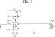
- FIG. 1 is a cross-sectional view illustrating a time-of-flight mass spectrometer according to an embodiment of the present invention.
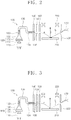
- FIG. 2 is a cross-sectional view illustrating a cold electron supply part and an ionization part of a time-of-flight mass spectrometer according to an embodiment of the present invention.
- a cold electron supply part 100 may be provided.
- the cold electron supply part 100 may not emit hot electrons but emit cold electrons using ultraviolet rays.
- the cold electron supply part 100 may include: an ultraviolet (UV) diode 110 emitting ultraviolet rays; a microchannel plate (MCP) 120 generating, multiplying, and emitting electron beams 'e' by using the ultraviolet rays; a channeltron electron multiplier 130 multiplying and emitting the electron beams 'e'; an inlet electrode 140 allowing the electron beams 'e' to be emitted without loss; an ion lens 150 focusing the electron beams 'e'; and a gate electrode 160 capable of controlling whether to emit the electron beams 'e'.
- the inner space of the cold electron supply part 100 may be substantially in a vacuum state. In an example, the inner space of the cold electron supply part 100 may have a pressure of about 10 -10 Torr to about 10 -4 Torr.
- the ultraviolet diode 110 may radiate ultraviolet rays toward the microchannel plate 120. Since the ultraviolet diode 110 uses current of several to several hundred mA level for several to several hundred micro-seconds, power consumption thereof may be small.
- the microchannel plate 120 facing the ultraviolet diode 110 may be provided.
- the microchannel plate 120 may generate, multiply, and emit electron beams 'e' by using ultraviolet rays.
- the microchannel plate 120 may have a front surface plate 122 facing the ultraviolet diode 110 and a rear surface plate 124 disposed on the side opposite to the front surface plate 122.
- the front surface plate 122 may accommodate ultraviolet rays provided from the ultraviolet diode 110 to thereby generate photoelectrons.
- the front surface plate 122 may have a negative voltage.
- the voltage of the front surface plate 122 may be about -3000 V to about -1000V
- Photoelectrons may be multiplied inside the microchannel plate. Multiplied photoelectrons may be referred to as electron beams 'e'.
- electron beams 'e' may be multiplied about to about 10 9 times more than photoelectrons.
- the rear surface plate 124 may emit the multiplied electron beams 'e'.
- the rear surface plate 124 may have a negative voltage.
- the voltage of the rear surface plate 124 may be about -3000 V to about - 1000V.
- the rear surface plate 124 may emit the electron beams 'e' toward the channeltron electron multiplier 130.
- the channeltron electron multiplier 130 may multiply the electron beams 'e' provided from the microchannel plate 120.
- the channeltron electron multiplier 130 may include an injection port 132, a first electrode 133, a multiflying tube 136, a second electrode 134, and an outlet port 138, which are sequentially disposed in this order.
- the electron beams 'e' may be multiplied through the injection port 132, the multiplying tube 136, and the outlet port 138. In an example, electron beams 'e' may be multiplied by about to about 10 9 times.
- the injection port 132 may be disposed adjacent to the rear surface plate 124 of the microchannel plate 120.
- the injection port 132 may have a conical shape.
- the injection port 132 may receive the electron beams 'e' from the microchannel plate 120. to thereby multiply the electron beams 'e'.
- the first electrode 133 may apply a negative voltage to the injection port 132.
- the first electrode 133 may apply a voltage substantially the same as the voltage of the rear surface plate 124 of the microchannel plate 120.
- the voltage which the first electrode 133 applies to the injection port 132 may be about -3000V to about -1000 V.
- the multiplying tube 136 and the outlet port 138 may multiply the electron beams 'e'.
- the second electrode 134 may apply a negative voltage to the outlet port 138.
- the second electrode 134 may apply a voltage higher than the voltage of the rear surface plate 124 to the outlet port 138.
- the voltage which the second electrode 134 applies to the outlet port 138 may be about -200 V to about 0 V.
- the inlet electrode 140 may increase the linearity of the electron beams 'e' in the channeltron electron multiplier 130 to thereby direct the electron beams 'e' toward the outlet port 138. Accordingly, the electron beams 'e' in the channeltron electron multiplier 130 may be emitted to the outside of the outlet port 138 without loss.
- the voltage of the inlet electrode 140 may be about -200 V to about 0V.
- the ion lens 150 may focus the electron beams 'e' emitted from the outlet port 138.
- the ion lens 150 may have a negative voltage.
- the ion lens 150 may have a voltage higher than the voltage applied to the rear surface plate 124 of the microchannel plate 120.
- the gate electrode 160 may block or allow the electron beams 'e' which have passed through the ion lens 150 to be injected into an ionization part 200.
- the gate electrode 160 may have on/off states. While the gate electrode 160 is in an on-state, the electron beams 'e' having passed through the ion lens 150 may pass through the gate electrode 160 to thereby be injected into the ionization part 200. While the gate electrode 160 is in an off-state, the electron beams 'e' having passed through the ion lens 150 may not be injected into the ionization part 200.
- An ionization part 200 generating ions I may be provided. Ions I may be generated by using the electron beams 'e' injected from the cold electron supply part 100.
- the ionization part 200 and the cold electron supply part 100 may share an inner space. Accordingly, the ionization part 200 may have a vacuum state substantially the same as the cold electron supply part 100.
- the inner space of the ionization part 200 may have a pressure of about 10 -10 Torr to about 10 -4 Torr.
- the ionization part 200 may include a sample part 210 in which a sample is disposed; and a mesh part 220 spaced apart from the sample part 210 in the direction perpendicular to the surface of the sample part 210.
- the mesh part 220 enables ions I emitted from the sample part 210 to have linearity.
- the mesh part 220 may have a grid shape. The ions I may pass through the mesh part 220.
- a positive voltage may be applied to the sample part 210, and a negative voltage may be applied to the mesh part 220. Accordingly, an electric field may be formed between the sample part 210 and the mesh part 220. The electric field may have a direction from the sample part 210 toward the mesh part 220.
- the electron beams 'e' injected into the ionization part 200 may be bent toward the sample part 210 by being forced by an electric field in the direction toward the sample part 210.
- a sample on the sample part 210 collides with the electron beams 'e' to thereby emit ions I.
- a gas sample G may be injected on the sample part 210.
- the gas sample G may be injected on the sample part 210 through a pulse method.
- the gas sample G may be adsorbed on the surface of the sample part 210.
- the sample adsorbed on the surface of the sample part 210 may collide with the electron beams 'e' injected in the cold electron supply part 100.
- ions I may be emitted from the sample.
- Ions I may include ions I having masses different from each other according to the composition of the sample.
- the ions I assume positive charges and may be forced in the direction from the sample part 210 toward the mesh part 220.
- the ions I may move to an ion separation part 300 through the mesh part 220.
- two or more mesh parts 220 may be provided. At this time, the mesh parts 220 may be disposed parallel to each other.
- An ion separation part 300 in which ions I having passed through the mesh part 220 are injected may be provided.
- the ion separation part 300 may have a straight tube shape.
- the ion separation part 300 may share an inner space with the ionization part 200 and the cold electron supply part 100 to thereby have a vacuum state.
- the inner space of the ion separation part 300 may have a pressure of about 10 -10 Torr to about 10 -4 Torr.
- the ions I generated in the ionization part may move to the ion detection part 400 through the ion separation part 300.
- the ion separation part 300 may extend from the surface of the sample part 210 in the direction perpendicular to the surface.
- the moving speed of ions I having relatively small masses may be faster than those of ions I having relatively great masses.
- the ions I having masses different from each other may have ion separation part-passing times different from each other.
- An ion detection part 400 detecting the ions I having passed through the ion separation part 300 may be provided.
- the ion detection part 400 may share an inner space with the ion separation part 300, the ionization part 200 and the cold electron supply part 100 to thereby have a vacuum state.
- the inner space of the ion detecting 400 may have a pressure of about 10 -10 Torr to about 10 -4 Torr.
- the ion detecting 400 may include a microchannel plate (not shown) and/or a channeltron electron multiplier (not shown). At this time, the microchannel plate and the channeltron electron multiplier may be substantially the same as the microchannel plate 120 and the channeltron electron multiplier 130 which are included in the cold electron supply part 100.
- ions I may be injected into the microchannel plate and/or the channeltron electron multiplier to thereby induce electrons. Electrons are amplified in the microchannel plate and/or the channeltron electron multiplier to be thereby detected by a detection circuit (not shown).
- a detection circuit not shown.
- a time-of-flight mass spectrometer including the cold electron supply part 100 may have a high accuracy.
- time-of-flight mass spectrometer having a required accuracy may be obtained. Accordingly, a time-of-flight mass spectrometer suitable for miniaturization may be provided.
- the time-of-flight mass spectrometer according to an exemplary embodiment may have small power consumption by using a ultraviolet diode.
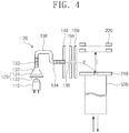
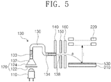
- FIGS. 3 to 5 are cross-sectional views of a cold electron supply part and an ionization part of a time-of-flight mass spectrometer according to an embodiment of the present invention. For simplicity in description, descriptions substantially the same as those described with reference to FIGS. 1 and 2 may not be provided.
- a liquid sample L may be provided on the sample part 210.
- the liquid sample L may be sprayed on the sample part 210 through a sample supply nozzle 510.
- the liquid sample L may be adsorbed on the surface of the sample part 210.
- the liquid sample collides with the electron beams 'e' to thereby generate ions I.
- Ions I may pass through the ion separation part to be thereby detected in the ion detection part.
- a solid sample rod 520 may be used as a sample.
- the solid sample rod 520 may collide with the electron beams 'e' to thereby generate ions I.
- Ions I may pass through the ion separation part to be thereby detected in the ion detection part.
- a matrix sample, a carbon nano-tube (CNT) or graphene 530 may be provided on the sample pat 210.
- the matrix sample, the carbon nano-tube (CNT) or graphene 530 may collide with the electron beams 'e' to thereby generate ions I.
- Ions I may pass through the ion separation part to be thereby detected in the ion detection part.
Landscapes
- Chemical & Material Sciences (AREA)
- Analytical Chemistry (AREA)
- Physics & Mathematics (AREA)
- Engineering & Computer Science (AREA)
- Plasma & Fusion (AREA)
- Other Investigation Or Analysis Of Materials By Electrical Means (AREA)
- Electron Tubes For Measurement (AREA)
Abstract
Description
- The present invention disclosed herein relates to a time-of-flight mass spectrometer, and more particularly, to a time-of-flight mass spectrometer using a cold electron beam as an ionization source.
- Time-of-flight mass spectrometers can ionize molecules having masses different from each other in a sample and measure current of generated ions. Time-of-flight mass spectrometers may be classified into various types according to methods of separating ions.
- A time-of-flight mass spectrometer is one of mass spectrometers. Time-of-flight mass spectrometers can measure masses of ions by using time-of flight of the ions. For an accurate mass spectrometry, a difference in ionizing time is minimized and electrons are thereby allowed to collide with a sample.
- The present invention provides a time-of-flight mass spectrometer having a high accuracy.
- The present invention also provides a time-of-flight mass spectrometer suitable to be made smaller.
- However, the problems to be solved by the present invention are not limited to the above disclosure.
- Embodiments of the present invention provide time-of-flight mass spectrometers including: an ionization part receiving electron beams to thereby emit ions; a cold electron supply part injecting the electron beams to the ionization part; an ion detection part detecting the ions emitted from the ionization part; and an ion separation part connecting the ionization part and the ion detection part, wherein the cold electron supply part includes a microchannel plate receiving ultraviolet rays to thereby emit the electron beams, the ions emitted from the ionization part pass through the ion separation part to thereby reach the ion detection part, and the ion separation part has a straight tube shape.
- In an embodiment, the cold electron supply part may further include an ultraviolet diode emitting the ultraviolet rays toward the microchannel plate.
- In an embodiment, the microchannel plate may include: a front surface plate receiving the ultraviolet rays to thereby generate electrons; and a rear surface plate emitting the electron beams, wherein the electron beams may be electrons multiplied in the microchannel plate.
- In an embodiment, the multiplication ratio may be about 104 times to about 109 times.
- In an embodiment, the cold electron supply part may further include a channeltron electron multiplier multiplying the electron beams emitted from the microchannel plate.
- In an embodiment, the channeltron electron multiplier may multiply the electron beams emitted from the microchannel plate by about times to about 109 times.
- In an embodiment, the cold electron supply part further may include an ion lens focusing the electron beams multiplied through the channeltron electron multiplier to thereby emit the electron beams toward the ionization part.
- In an embodiment, the cold electron supply part may further include a gate electrode blocking or allowing the electron beams emitted from the ion lens to be injected into the ionization part.
- In an embodiment, the ion detection part may receive the ions to thereby generate, amplify, and detect electrons and may include a microchannel plate or channeltron electron multiplier which amplifies the electrons.
- In an embodiment, the time-of-flight mass spectrometer may have an inner space in vacuum.
- In an embodiment, the time-of-flight mass spectrometer may have a pressure of about 10-10 Torr to about 10-4 Torr in the inner space.
- In an embodiment, the ionization part may include: a sample part on which the sample collides with the electron beams to thereby generate ions; and a sample supply part supplying the sample on the sample part.
- In an embodiment, the sample supply part may spray a gas sample to the sample part and the gas sample may be adsorbed on an upper surface of the sample part.
- In an embodiment, the sample supply part may supply the gas sample on the sample part through a pulse method.
- In an embodiment, the sample supply part may spray a gas sample to the sample part and the gas sample may be adsorbed on an upper surface of the sample part.
- According to an embodiment of the present invention, a time-of-flight mass spectrometer in which differences in ionization times of ions are small may be provided. Accordingly, the accuracy of the time-of-flight mass spectrometer may be high.
- According to an embodiment of the present invention, time-of-flight mass spectrometers which have small power consumption and high accuracy may be provided. Accordingly, time-of-flight mass spectrometers suitable for miniaturization may be provided.
- However, the effects of the present invention are not limited to the above disclosure.
-
-
FIG. 1 is a cross-sectional view illustrating a time-of-flight mass spectrometer according to an embodiment of the present invention; -
FIG. 2 is a cross-sectional view illustrating a cold electron supply part and an ionization part of a time-of-flight mass spectrometer according to an embodiment of the present invention; and -
FIGS. 3 to 5 are cross-sectional views of a cold electron supply part and an ionization part of a time-of-flight mass spectrometer according to an embodiment of the present invention. - For sufficient understanding of the configuration and effects of the present invention, exemplary embodiments of the present disclosure will be described in detail with reference to the accompanying drawings. The present invention may, however, be embodied in many alternate forms and should not be construed as limited to only the embodiments set forth herein. Rather, these embodiments are provided so that this disclosure will be thorough and complete, and will fully convey the scope of the present disclosure to those skilled in the art.
-
FIG. 1 is a cross-sectional view illustrating a time-of-flight mass spectrometer according to an embodiment of the present invention.FIG. 2 is a cross-sectional view illustrating a cold electron supply part and an ionization part of a time-of-flight mass spectrometer according to an embodiment of the present invention. - Referring to
FIGS. 1 and2 , a coldelectron supply part 100 may be provided. The coldelectron supply part 100 may not emit hot electrons but emit cold electrons using ultraviolet rays. The coldelectron supply part 100 may include: an ultraviolet (UV)diode 110 emitting ultraviolet rays; a microchannel plate (MCP) 120 generating, multiplying, and emitting electron beams 'e' by using the ultraviolet rays; a channeltron electron multiplier 130 multiplying and emitting the electron beams 'e'; aninlet electrode 140 allowing the electron beams 'e' to be emitted without loss; anion lens 150 focusing the electron beams 'e'; and agate electrode 160 capable of controlling whether to emit the electron beams 'e'. The inner space of the coldelectron supply part 100 may be substantially in a vacuum state. In an example, the inner space of the coldelectron supply part 100 may have a pressure of about 10-10 Torr to about 10-4 Torr. - The
ultraviolet diode 110 may radiate ultraviolet rays toward themicrochannel plate 120. Since theultraviolet diode 110 uses current of several to several hundred mA level for several to several hundred micro-seconds, power consumption thereof may be small. - The
microchannel plate 120 facing theultraviolet diode 110 may be provided. Themicrochannel plate 120 may generate, multiply, and emit electron beams 'e' by using ultraviolet rays. Themicrochannel plate 120 may have afront surface plate 122 facing theultraviolet diode 110 and arear surface plate 124 disposed on the side opposite to thefront surface plate 122. Thefront surface plate 122 may accommodate ultraviolet rays provided from theultraviolet diode 110 to thereby generate photoelectrons. Thefront surface plate 122 may have a negative voltage. For example, the voltage of thefront surface plate 122 may be about -3000 V to about -1000V Photoelectrons may be multiplied inside the microchannel plate. Multiplied photoelectrons may be referred to as electron beams 'e'. In an example, electron beams 'e' may be multiplied about to about 109 times more than photoelectrons. Therear surface plate 124 may emit the multiplied electron beams 'e'. Therear surface plate 124 may have a negative voltage. For example, the voltage of therear surface plate 124 may be about -3000 V to about - 1000V. Therear surface plate 124 may emit the electron beams 'e' toward thechanneltron electron multiplier 130. - The
channeltron electron multiplier 130 may multiply the electron beams 'e' provided from themicrochannel plate 120. Thechanneltron electron multiplier 130 may include aninjection port 132, afirst electrode 133, amultiflying tube 136, asecond electrode 134, and anoutlet port 138, which are sequentially disposed in this order. The electron beams 'e' may be multiplied through theinjection port 132, the multiplyingtube 136, and theoutlet port 138. In an example, electron beams 'e' may be multiplied by about to about 109 times. - The
injection port 132 may be disposed adjacent to therear surface plate 124 of themicrochannel plate 120. Theinjection port 132 may have a conical shape. Theinjection port 132 may receive the electron beams 'e' from themicrochannel plate 120. to thereby multiply the electron beams 'e'. Thefirst electrode 133 may apply a negative voltage to theinjection port 132. In an example, thefirst electrode 133 may apply a voltage substantially the same as the voltage of therear surface plate 124 of themicrochannel plate 120. For example, the voltage which thefirst electrode 133 applies to theinjection port 132 may be about -3000V to about -1000 V. The multiplyingtube 136 and theoutlet port 138 may multiply the electron beams 'e'. Thesecond electrode 134 may apply a negative voltage to theoutlet port 138. In an example, thesecond electrode 134 may apply a voltage higher than the voltage of therear surface plate 124 to theoutlet port 138. For example, the voltage which thesecond electrode 134 applies to theoutlet port 138 may be about -200 V to about 0 V. - The
inlet electrode 140 may increase the linearity of the electron beams 'e' in thechanneltron electron multiplier 130 to thereby direct the electron beams 'e' toward theoutlet port 138. Accordingly, the electron beams 'e' in thechanneltron electron multiplier 130 may be emitted to the outside of theoutlet port 138 without loss. In an example, the voltage of theinlet electrode 140 may be about -200 V to about 0V. Theion lens 150 may focus the electron beams 'e' emitted from theoutlet port 138. Theion lens 150 may have a negative voltage. In an example, theion lens 150 may have a voltage higher than the voltage applied to therear surface plate 124 of themicrochannel plate 120. Thegate electrode 160 may block or allow the electron beams 'e' which have passed through theion lens 150 to be injected into anionization part 200. For example, thegate electrode 160 may have on/off states. While thegate electrode 160 is in an on-state, the electron beams 'e' having passed through theion lens 150 may pass through thegate electrode 160 to thereby be injected into theionization part 200. While thegate electrode 160 is in an off-state, the electron beams 'e' having passed through theion lens 150 may not be injected into theionization part 200. - An
ionization part 200 generating ions I may be provided. Ions I may be generated by using the electron beams 'e' injected from the coldelectron supply part 100. Theionization part 200 and the coldelectron supply part 100 may share an inner space. Accordingly, theionization part 200 may have a vacuum state substantially the same as the coldelectron supply part 100. In an example, the inner space of theionization part 200 may have a pressure of about 10-10 Torr to about 10-4 Torr. Theionization part 200 may include asample part 210 in which a sample is disposed; and amesh part 220 spaced apart from thesample part 210 in the direction perpendicular to the surface of thesample part 210. Themesh part 220 enables ions I emitted from thesample part 210 to have linearity. Themesh part 220 may have a grid shape. The ions I may pass through themesh part 220. - A positive voltage may be applied to the
sample part 210, and a negative voltage may be applied to themesh part 220. Accordingly, an electric field may be formed between thesample part 210 and themesh part 220. The electric field may have a direction from thesample part 210 toward themesh part 220. The electron beams 'e' injected into theionization part 200 may be bent toward thesample part 210 by being forced by an electric field in the direction toward thesample part 210. A sample on thesample part 210 collides with the electron beams 'e' to thereby emit ions I. - In an example, a gas sample G may be injected on the
sample part 210. For example, the gas sample G may be injected on thesample part 210 through a pulse method. The gas sample G may be adsorbed on the surface of thesample part 210. The sample adsorbed on the surface of thesample part 210 may collide with the electron beams 'e' injected in the coldelectron supply part 100. Accordingly, ions I may be emitted from the sample. Ions I may include ions I having masses different from each other according to the composition of the sample. The ions I assume positive charges and may be forced in the direction from thesample part 210 toward themesh part 220. The ions I may move to anion separation part 300 through themesh part 220. In an example, two ormore mesh parts 220 may be provided. At this time, themesh parts 220 may be disposed parallel to each other. - An
ion separation part 300 in which ions I having passed through themesh part 220 are injected may be provided. Theion separation part 300 may have a straight tube shape. Theion separation part 300 may share an inner space with theionization part 200 and the coldelectron supply part 100 to thereby have a vacuum state. In an example, the inner space of theion separation part 300 may have a pressure of about 10-10 Torr to about 10-4 Torr. The ions I generated in the ionization part may move to theion detection part 400 through theion separation part 300. Theion separation part 300 may extend from the surface of thesample part 210 in the direction perpendicular to the surface. The moving speed of ions I having relatively small masses may be faster than those of ions I having relatively great masses. The ions I having masses different from each other may have ion separation part-passing times different from each other. - An
ion detection part 400 detecting the ions I having passed through theion separation part 300 may be provided. Theion detection part 400 may share an inner space with theion separation part 300, theionization part 200 and the coldelectron supply part 100 to thereby have a vacuum state. In an example, the inner space of the ion detecting 400 may have a pressure of about 10-10 Torr to about 10-4 Torr. In an example, the ion detecting 400 may include a microchannel plate (not shown) and/or a channeltron electron multiplier (not shown). At this time, the microchannel plate and the channeltron electron multiplier may be substantially the same as themicrochannel plate 120 and thechanneltron electron multiplier 130 which are included in the coldelectron supply part 100. For example, ions I may be injected into the microchannel plate and/or the channeltron electron multiplier to thereby induce electrons. Electrons are amplified in the microchannel plate and/or the channeltron electron multiplier to be thereby detected by a detection circuit (not shown). When ions I having relatively small masses and ions I having relatively great masses simultaneously enter theion separation part 300, the ions I having relatively small masses may be detected earlier than the ions I having relatively great masses. The longer the length of theion separation part 300, the greater the difference in times within which the ions I having different masses different from each other be detected. - The smaller the difference in an ionizing time within which molecules having masses different from each other collides with electron beams 'e' to emit ions, the higher the accuracy of a time-of-flight mass spectrometer. When cold electrons are used as an ionization source, the differences in the ionizing time of the ions having masses different from each other may be several to several hundred nanoseconds. Accordingly, a time-of-flight mass spectrometer including the cold
electron supply part 100 may have a high accuracy. - Even when the length of the
ion separation part 300 by using cold electrons as ionization source is formed smaller that that in the case of using an ionization source other than cold electrons, a time-of-flight mass spectrometer having a required accuracy may be obtained. Accordingly, a time-of-flight mass spectrometer suitable for miniaturization may be provided. In addition, the time-of-flight mass spectrometer according to an exemplary embodiment may have small power consumption by using a ultraviolet diode. -
FIGS. 3 to 5 are cross-sectional views of a cold electron supply part and an ionization part of a time-of-flight mass spectrometer according to an embodiment of the present invention. For simplicity in description, descriptions substantially the same as those described with reference toFIGS. 1 and2 may not be provided. - Referring to
FIG. 3 , a liquid sample L may be provided on thesample part 210. The liquid sample L may be sprayed on thesample part 210 through asample supply nozzle 510. The liquid sample L may be adsorbed on the surface of thesample part 210. The liquid sample collides with the electron beams 'e' to thereby generate ions I. Ions I may pass through the ion separation part to be thereby detected in the ion detection part. - Referring to
FIG. 4 , asolid sample rod 520 may be used as a sample. Thesolid sample rod 520 may collide with the electron beams 'e' to thereby generate ions I. Ions I may pass through the ion separation part to be thereby detected in the ion detection part. - Referring to
FIG. 5 , a matrix sample, a carbon nano-tube (CNT) orgraphene 530 may be provided on thesample pat 210. The matrix sample, the carbon nano-tube (CNT) orgraphene 530 may collide with the electron beams 'e' to thereby generate ions I. Ions I may pass through the ion separation part to be thereby detected in the ion detection part. - The above description on embodiments of the present invention provides exemplary examples for describing the present invention. Thus, the present invention is not limited to the above-described embodiments, and it would be clarified that various modifications and changes, for example, combinations of the above embodiments, could be made by those skilled in the art within the technical spirit and scope of the present invention.
Claims (15)
- A time-of-flight mass spectrometer comprising:an ionization part receiving electron beams and to thereby emit ions;a cold electron supply part injecting the electron beams to the ionization part;an ion detection part detecting the ions emitted from the ionization part; andan ion separation part connecting the ionization part and the ion detection part, whereinthe cold electron supply part comprises a microchannel plate receiving ultraviolet rays to thereby emit the electron beams,the ions emitted from the ionization part pass through the ion separation part to thereby reach the ion detection part, andthe ion separation part has a straight tube shape.
- The time-of-flight mass spectrometer of claim 1, wherein the cold electron supply part further comprises an ultraviolet diode emitting the ultraviolet rays toward the microchannel plate.
- The time-of-flight mass spectrometer of claim 1, wherein the microchannel plate comprises:a front surface plate receiving the ultraviolet rays to thereby generate electrons; anda rear surface plate emitting the electron beams, whereinthe electron beams are electrons multiplied in the microchannel plate.
- The time-of-flight mass spectrometer of claim 3, wherein the multiplication ratio is about times to about 109 times
- The time-of-flight mass spectrometer of claim 1, wherein the cold electron supply part further comprises a channeltron electron multiplier multiplying the electron beams emitted from the microchannel plate.
- The time-of-flight mass spectrometer of claim 5, wherein the channeltron electron multiplier multiplies the electron beams emitted from the microchannel plate by about times to about 109 times.
- The time-of-flight mass spectrometer of claim 5, wherein the cold electron supply part further comprises an ion lens focusing the electron beams multiplied through the channeltron electron multiplier to thereby emit the electron beams toward the ionization part.
- The time-of-flight mass spectrometer of claim 7, wherein the cold electron supply part further comprises a gate electrode blocking or allowing the electron beams emitted from the ion lens to be injected into the ionization part.
- The time-of-flight mass spectrometer of claim 1, wherein the ion detection part receives the ions to thereby generate, amplify, and detect electrons and comprises a microchannel plate or channeltron electron multiplier which amplifies the electrons.
- The time-of-flight mass spectrometer of claim 1, wherein the time-of-flight mass spectrometer has an inner space in vacuum.
- The time-of-flight mass spectrometer of claim 1, wherein the time-of-flight mass spectrometer has a pressure of about 10-10 Torr to about 10-4 Torr in the inner space.
- The time-of-flight mass spectrometer of claim 1, wherein the ionization part comprises a sample part on which the sample collides with the electron beams to thereby generate ions; and a sample supply part supplying the sample on the sample part.
- The time-of-flight mass spectrometer of claim 12, wherein the sample supply part sprays a gas sample to the sample part and the gas sample is adsorbed on an upper surface of the sample part.
- The time-of-flight mass spectrometer of claim 13, wherein the sample supply part supplies the gas sample on the sample part through a pulse method.
- The time-of-flight mass spectrometer of claim 13, wherein the sample supply part sprays a liquid sample on the sample part and the liquid sample is adsorbed on the sample part.
Applications Claiming Priority (3)
| Application Number | Priority Date | Filing Date | Title |
|---|---|---|---|
| KR20140194149 | 2014-12-30 | ||
| KR1020150171695A KR101786950B1 (en) | 2014-12-30 | 2015-12-03 | Time of flight mass spectrometer |
| PCT/KR2015/013252 WO2016108451A2 (en) | 2014-12-30 | 2015-12-04 | Time-of-flight mass spectrometer |
Publications (2)
| Publication Number | Publication Date |
|---|---|
| EP3147933A2 true EP3147933A2 (en) | 2017-03-29 |
| EP3147933A4 EP3147933A4 (en) | 2018-08-08 |
Family
ID=56505278
Family Applications (1)
| Application Number | Title | Priority Date | Filing Date |
|---|---|---|---|
| EP15875545.4A Withdrawn EP3147933A4 (en) | 2014-12-30 | 2015-12-04 | Time-of-flight mass spectrometer |
Country Status (4)
| Country | Link |
|---|---|
| US (1) | US10388506B2 (en) |
| EP (1) | EP3147933A4 (en) |
| JP (1) | JP6346965B2 (en) |
| KR (1) | KR101786950B1 (en) |
Families Citing this family (2)
| Publication number | Priority date | Publication date | Assignee | Title |
|---|---|---|---|---|
| KR102731520B1 (en) | 2021-12-09 | 2024-11-21 | 주식회사 다인템 | Time-Of-Flight Mass Spectrometer Including All-in-one Ion Optics |
| CN116153761B (en) * | 2023-04-21 | 2023-07-11 | 浙江迪谱诊断技术有限公司 | Time-of-flight mass spectrometer |
Family Cites Families (18)
| Publication number | Priority date | Publication date | Assignee | Title |
|---|---|---|---|---|
| FR66032E (en) | 1952-11-26 | |||
| US5659170A (en) * | 1994-12-16 | 1997-08-19 | The Texas A&M University System | Ion source for compact mass spectrometer and method of mass analyzing a sample |
| CN100525876C (en) * | 1998-09-17 | 2009-08-12 | 阿德文生物系统公司 | Electrospray nozzle and monolithic substrate |
| FR2792773B1 (en) | 1999-04-22 | 2001-07-27 | Cit Alcatel | ION SOURCE FOR TIME OF FLIGHT MASS SPECTROMETER ANALYZING GASEOUS SAMPLES |
| WO2001078880A1 (en) * | 2000-04-12 | 2001-10-25 | The Regents Of The University Of California | Method of reducing ion fragmentation in mass spectrometry |
| US6747271B2 (en) * | 2001-12-19 | 2004-06-08 | Ionwerks | Multi-anode detector with increased dynamic range for time-of-flight mass spectrometers with counting data acquisition |
| KR20040034252A (en) | 2002-10-21 | 2004-04-28 | 삼성전자주식회사 | Matrix assisted laser desorption ionization time of flight mass spectrometry |
| CN101952703A (en) | 2007-12-19 | 2011-01-19 | 布鲁克机械公司 | Ionization gauge having electron multiplier cold emmission source |
| CN104779132B (en) * | 2009-05-06 | 2018-04-13 | Mks仪器公司 | Electrostatic ion trap |
| US8461521B2 (en) * | 2010-12-14 | 2013-06-11 | Virgin Instruments Corporation | Linear time-of-flight mass spectrometry with simultaneous space and velocity focusing |
| US8035081B2 (en) * | 2009-09-30 | 2011-10-11 | The United States Of America As Represented By The Administrator Of The National Aeronautics And Space Administration | High precision electric gate for time-of-flight ion mass spectrometers |
| JP5771458B2 (en) * | 2011-06-27 | 2015-09-02 | 株式会社日立ハイテクノロジーズ | Mass spectrometer and mass spectrometry method |
| WO2013042829A1 (en) * | 2011-09-20 | 2013-03-28 | 한국기초과학지원연구원 | Ultraviolet diode and atomic mass analysis ionization source collecting device using an ultraviolet diode and an mcp |
| KR101319925B1 (en) | 2011-09-20 | 2013-10-21 | 한국기초과학지원연구원 | Apparatus for Acquiring Ion source of Mass spectrometry using UV LED and CEM |
| US9230791B2 (en) * | 2011-11-28 | 2016-01-05 | Korea Basic Science Institute | Anion generating and electron capture dissociation apparatus using cold electrons |
| JP6163068B2 (en) | 2013-09-19 | 2017-07-12 | 浜松ホトニクス株式会社 | MCP unit, MCP detector and time-of-flight mass analyzer |
| KR101547210B1 (en) | 2013-12-05 | 2015-08-25 | 한국기초과학지원연구원 | Ion Trap Mass spectrometer using Cold Electron Source |
| WO2016020678A1 (en) * | 2014-08-05 | 2016-02-11 | Micromass Uk Limited | Method of introducing ions into a vacuum region of a mass spectrometer |
-
2015
- 2015-12-03 KR KR1020150171695A patent/KR101786950B1/en active Active
- 2015-12-04 JP JP2016575356A patent/JP6346965B2/en not_active Expired - Fee Related
- 2015-12-04 US US15/321,563 patent/US10388506B2/en active Active
- 2015-12-04 EP EP15875545.4A patent/EP3147933A4/en not_active Withdrawn
Also Published As
| Publication number | Publication date |
|---|---|
| JP2017525095A (en) | 2017-08-31 |
| US10388506B2 (en) | 2019-08-20 |
| KR20160083799A (en) | 2016-07-12 |
| KR101786950B1 (en) | 2017-10-19 |
| EP3147933A4 (en) | 2018-08-08 |
| US20170294298A1 (en) | 2017-10-12 |
| JP6346965B2 (en) | 2018-06-20 |
Similar Documents
| Publication | Publication Date | Title |
|---|---|---|
| CA2661703C (en) | Method and apparatus for detecting positively charged and negatively charged ionized particles | |
| US9543138B2 (en) | Ion optical system for MALDI-TOF mass spectrometer | |
| JP6489240B2 (en) | Orthogonal acceleration time-of-flight mass spectrometer | |
| US20170278690A1 (en) | Ionization device with mass spectrometer therewith | |
| CN103959428B (en) | For applying the system and method for heavy curtain air-flow in a mass spectrometer | |
| JP2020506524A (en) | Fourier transform mass spectrometer | |
| JP2018073703A (en) | Mass spectrometer | |
| US9412576B2 (en) | Ion trap mass spectrometer using cold electron source | |
| US9570282B2 (en) | Ionization within ion trap using photoionization and electron ionization | |
| US10388506B2 (en) | Time-of-flight mass spectrometer using a cold electron beam as an ionization source | |
| JP6717429B2 (en) | Ion detector and mass spectrometer | |
| US8927943B2 (en) | Device for obtaining the ion source of a mass spectrometer using an ultraviolet diode and a CEM | |
| US6545269B1 (en) | Ion source for time-of-flight mass spectrometers for analyzing gas samples | |
| JP7548156B2 (en) | Mass Spectrometer | |
| US20230207302A1 (en) | Mass spectrometer | |
| WO2016108451A2 (en) | Time-of-flight mass spectrometer | |
| JP7497779B2 (en) | Mass Spectrometer | |
| US11587776B1 (en) | Ion detection systems | |
| WO2019016851A1 (en) | Mass spectroscope | |
| JP2023016583A (en) | Orthogonal acceleration time-of-flight mass spectrometer |
Legal Events
| Date | Code | Title | Description |
|---|---|---|---|
| STAA | Information on the status of an ep patent application or granted ep patent |
Free format text: STATUS: THE INTERNATIONAL PUBLICATION HAS BEEN MADE |
|
| PUAI | Public reference made under article 153(3) epc to a published international application that has entered the european phase |
Free format text: ORIGINAL CODE: 0009012 |
|
| STAA | Information on the status of an ep patent application or granted ep patent |
Free format text: STATUS: REQUEST FOR EXAMINATION WAS MADE |
|
| 17P | Request for examination filed |
Effective date: 20161221 |
|
| AK | Designated contracting states |
Kind code of ref document: A2 Designated state(s): AL AT BE BG CH CY CZ DE DK EE ES FI FR GB GR HR HU IE IS IT LI LT LU LV MC MK MT NL NO PL PT RO RS SE SI SK SM TR |
|
| AX | Request for extension of the european patent |
Extension state: BA ME |
|
| RIC1 | Information provided on ipc code assigned before grant |
Ipc: H01J 49/14 20060101ALI20180220BHEP Ipc: H01J 43/24 20060101ALN20180220BHEP Ipc: H01J 49/40 20060101ALN20180220BHEP Ipc: H01J 49/08 20060101AFI20180220BHEP |
|
| DAV | Request for validation of the european patent (deleted) | ||
| DAX | Request for extension of the european patent (deleted) | ||
| A4 | Supplementary search report drawn up and despatched |
Effective date: 20180706 |
|
| RIC1 | Information provided on ipc code assigned before grant |
Ipc: H01J 49/40 20060101ALN20180702BHEP Ipc: H01J 43/24 20060101ALN20180702BHEP Ipc: H01J 49/08 20060101AFI20180702BHEP Ipc: H01J 49/14 20060101ALI20180702BHEP |
|
| STAA | Information on the status of an ep patent application or granted ep patent |
Free format text: STATUS: EXAMINATION IS IN PROGRESS |
|
| 17Q | First examination report despatched |
Effective date: 20200313 |
|
| STAA | Information on the status of an ep patent application or granted ep patent |
Free format text: STATUS: THE APPLICATION HAS BEEN WITHDRAWN |
|
| 18W | Application withdrawn |
Effective date: 20200603 |