EP3147697A1 - System für optischen zoom - Google Patents
System für optischen zoom Download PDFInfo
- Publication number
- EP3147697A1 EP3147697A1 EP15186595.3A EP15186595A EP3147697A1 EP 3147697 A1 EP3147697 A1 EP 3147697A1 EP 15186595 A EP15186595 A EP 15186595A EP 3147697 A1 EP3147697 A1 EP 3147697A1
- Authority
- EP
- European Patent Office
- Prior art keywords
- optical
- lenses
- optical system
- zoom
- plane
- Prior art date
- Legal status (The legal status is an assumption and is not a legal conclusion. Google has not performed a legal analysis and makes no representation as to the accuracy of the status listed.)
- Withdrawn
Links
Images









Classifications
-
- G—PHYSICS
- G02—OPTICS
- G02B—OPTICAL ELEMENTS, SYSTEMS OR APPARATUS
- G02B13/00—Optical objectives specially designed for the purposes specified below
- G02B13/08—Anamorphotic objectives
- G02B13/12—Anamorphotic objectives with variable magnification
-
- G—PHYSICS
- G02—OPTICS
- G02B—OPTICAL ELEMENTS, SYSTEMS OR APPARATUS
- G02B27/00—Optical systems or apparatus not provided for by any of the groups G02B1/00 - G02B26/00, G02B30/00
- G02B27/09—Beam shaping, e.g. changing the cross-sectional area, not otherwise provided for
- G02B27/0911—Anamorphotic systems
-
- G—PHYSICS
- G02—OPTICS
- G02B—OPTICAL ELEMENTS, SYSTEMS OR APPARATUS
- G02B27/00—Optical systems or apparatus not provided for by any of the groups G02B1/00 - G02B26/00, G02B30/00
- G02B27/09—Beam shaping, e.g. changing the cross-sectional area, not otherwise provided for
- G02B27/0927—Systems for changing the beam intensity distribution, e.g. Gaussian to top-hat
Definitions
- the present invention is generally related to the field of optical zoom systems.
- Some applications for industrial materials processing with lasers come along with a variety of different requirements on the delivered beam irradiance distribution.
- flat-top beams provide benefits for applications like surface heat treatment or welding, in which it is desirable to uniformly illuminate a target surface.
- Other applications like drilling and photo-polymerization, can benefit from different beam profiles such as Bessel or annular beams.
- the complexity of how to reach these imposed requirements is further increased due to the number of different commercially available laser sources, ranging from tens of Watt to tens of kWatt. Certain applications can additionally benefit from time-varying distributions.
- a dynamic beam shaping system has been developed based on scanning mirror optics for laser beam hardening, proving a variable scan width, whereby the energy spread is adaptable to different local heat flow conditions.
- deformable mirrors and spatial light modulators has been also proposed to achieve adaptive laser beam irradiance control.
- adaptive concepts are very versatile, their optical efficiency might be significantly reduced and the used adaptive optics might tolerate only limited energy densities.
- a very common approach is the design of dynamic laser beam systems based on movable lenses. Zoom beam expanders are a well-known example and widely commercially available, e.g. for applications where the exactly required expansion ratio is unknown.
- Fig.1 The basic working principle of such an optical zoom system is illustrated in Fig.1 , by means of a system with three lenses (and four optical surfaces). The shown movement results in a variable magnification of a collimated laser beam.
- the lens profiles can be used to build a rotationally or cylindrically symmetric system.
- the final beam shaping optics can be either constructed as a rotationally symmetric or a cylindrical zoom lens, depending on whether a radial magnification or magnification along one axis is needed. A sufficient number of lenses is needed in case diffraction limited performance is to be provided over the full zoom range. In practical systems there are often three groups of lenses which possibly contain more than one lens.
- a zoom lens is a mechanical assembly of lens elements, typically in several air spaced groups, for which the focal length can be varied, as opposed to a fixed focal length lens.
- An afocal system i.e. a system without focus
- Zoom lenses offer the convenience of variable focal length (e.g. in imaging applications) or different beam diameters (e.g. in zoom beam expanders). They can only achieve this convenience through compromises on optical performance throughout the full zoom range, for different wavelengths, weight and dimensions (number of used optical elements).
- a train of air spaced optical mechanisms is capable of taking a raw laser beam and focusing it on a workpiece for a range of cut sizes with varying magnifications and energy densities while controlling divergence and providing optimum uniformity.
- the lenses are diffraction limited for optimum uniformity and edge definition.
- the system uses variable down collimators to condense the beam to an aperture plane. The aperture is then imaged to the workpiece with Barlow, zoom transfer, collimator and objective lenses.
- optical zoom systems to date make use of rotationally symmetric (spherical and/or aspherical) and/or cylindrically symmetric lenses to achieve continuous variation of some of the optical beam properties. These continuous variations possess the same symmetry of the optical zoom system, i.e. either rotational or cylindrical symmetry.
- Combinations of several sub-systems that may be rotated relative to each other are necessary to achieve a more complex zoom performance that cannot be achieved with a single system. Examples of such combinations, with or without relative rotation, can be found e.g. in the above-mentioned Nadorff paper and in US5095386 .
- the invention in a first aspect relates to an optical zoom system comprising a zoom lens system with at least two lenses and means for moving the at least two lenses with respect to one another in a given direction so that at least one energy or irradiance distribution of the received light can be generated, whereby at least one of the lenses has at least one freeform shaped optical surface.
- the proposed solution indeed allows for variation of beam shape and/or wave front, both in an afocal zoom system and at a given reference plane.
- the beam irradiance distribution and/or wave front can be varied in size and/or shape by changing the relative position of the at least two lenses and are no longer limited to rotational or cylindrical symmetry.
- This variation is realised by properly designing the freeform element(s).
- the shape of the freeform element(s) has a direct impact on the shape of the output irradiance distribution and/or wave front, which takes away the limitation to rotational or cylindrical symmetry.
- the energy or irradiance output distribution is variable, there are at least two output distributions.
- the received light has at least two input distributions while there is only one output distribution.
- the at least one freeform shaped optical surface has symmetry imposed by one or more symmetry properties of said at least one energy or irradiance output distribution, of an energy or irradiance input distribution of the received light or of both.
- the at least one freeform shaped optical surface has symmetry imposed by symmetry (one or more symmetry properties?) of an energy or irradiance input distribution of the received light.
- the symmetry is typically mirror symmetry or n-fold rotational symmetry, but also other symmetries are possible.
- the energy or irradiance output distribution is fixed and the received light has a variable energy or irradiance input distribution.
- the energy or irradiance output distribution is variable and the received light has a fixed energy or irradiance input distribution.
- the means for moving said at least two lenses is stepper motor or a MEMS (microelectromechanical system) device.
- the given direction is a common axis of the at least two lenses.
- the energy or irradiance output distribution is generated in a reference surface.
- the reference surface may be tilted with respect to the given direction.
- the zoom lens system comprises at least three lenses.
- the zoom lens system is an afocal zoom system.
- the optical zoom system comprises a light source.
- the optical zoom system is arranged for generating different variable magnifications in x and y direction.
- the optical system comprises at least one diffractive optical element or phase element. This allows for additional control on the wave fronts.
- Fig.1 illustrates the working principle of a basic afocal optical zoom system.
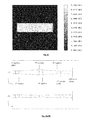
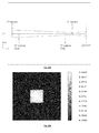
- Fig.2A and 2B illustrate the cross sections in the x-z and y-z plane, respectively, of an optical zoom system operating as an XY beam expander with different magnifications in x- and y-direction in an afocal configuration.
- the output intensity remains unchanged and the optical system provides a magnification of 2x in x-direction and 0.5x in y-direction.
- Fig.2C illustrates the corresponding intensity distribution with 12mm x 3mm side lengths, for a squared flat-top intensity distribution of 6mm x 6mm side lengths at the input.
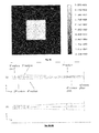
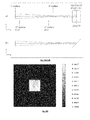
- Fig.3A and 3B illustrate the cross sections in the x-z and y-z plane, respectively, of an optical zoom system operating as an XY beam expander with different magnifications in x- and y-direction in an afocal configuration.
- the output intensity remains unchanged and the optical system provides a magnification of 1x in x-direction and 1x in y-direction, the neutral position.
- Fig.3C illustrates the corresponding intensity distribution with 6mm x 6mm side lengths, for a squared flat-top intensity distribution of 6mm x 6mm side lengths at the input.
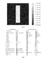
- Fig.4A and 4B illustrate the cross sections in the x-z and y-z plane, respectively, of an optical zoom system operating as an XY beam expander with different magnifications in x- and y-direction in an afocal configuration.
- the output intensity remains unchanged and the optical system provides a magnification of 0.5x in x-direction and 2x in y-direction.
- Fig.4C illustrates the corresponding intensity distribution with 3mm x 12mm side lengths, for a squared flat-top intensity distribution of 6mm x 6mm side lengths at the input.
- Fig.5 illustrates two configurations similar to those in Fig.12 and 14 , wherein the required initial values and functions are indicated to derive the conditional equations from Fermat's principle.
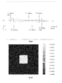
- Fig.6A illustrates the cross sections both in the x-z and y-z plane of an optical zoom system that transforms a Gaussian input beam to a squared flat-top intensity distribution with variable side length in an afocal configuration.
- the output intensity distribution in a given reference plane behind the optical zoom system has a side length of 12mm.
- Fig.6B illustrates the corresponding intensity distribution.
- Fig.7A illustrates the cross sections both in the x-z and y-z plane of an optical zoom system that transforms a Gaussian input beam to a squared flat-top intensity distribution with variable side length in an afocal configuration.
- the output intensity distribution in a given reference plane behind the optical zoom system has a side length of 8mm.
- Fig.7B illustrates the corresponding intensity distribution.
- Fig.8A illustrates the cross sections both in the x-z and y-z plane of an optical zoom system that transforms a Gaussian input beam to a squared flat-top intensity distribution with variable side length in an afocal configuration.
- the output intensity distribution in a given reference plane behind the optical zoom system has a side length of 4mm.
- Fig.8B illustrates the corresponding intensity distribution.
- Fig.9 illustrates the cross section both in x-z and y-z plane of an optical zoom system that transforms a collimated Gaussian input beam to a squared flat-top intensity distribution with side length of 12mm in plane D.
- Fig.10 illustrates the intensity distribution related to Fig.9 .
- Fig.11A illustrates the cross section both in x-z and y-z plane of an optical zoom system after the lenses have been moved, that transforms a Gaussian input beam to a squared flat-top intensity distribution with side length of 8mm in plane D.
- Fig.11B shows the intensity distribution.
- Fig.12A illustrates the cross section both in x-z and y-z plane of an optical zoom system after the lenses have been moved, that transforms a Gaussian input beam to a squared flat-top intensity distribution with side length of 4mm in plane D.
- Fig.12B shows the intensity distribution.
- Fig.13A and 13B illustrates illustrate the cross sections in the x-z and y-z plane of an optical zoom system that transforms a Gaussian input beam to a squared flat-top intensity distribution with side length of 12mm in a 45° tilted plane D.
- Fig.13C illustrates the corresponding intensity distribution.
- Fig.14A and 14B illustrate the cross sections in the x-z and y-z plane of an optical zoom system after the lenses have been moved, that transforms a Gaussian input beam to a squared flat-top intensity distribution with side length of 8mm in a 45° tilted plane D.
- Fig.14C illustrates the corresponding intensity distribution.
- Fig.15A and 15B illustrate the cross sections in the x-z and y-z plane of an optical zoom system after the lenses have been moved, that transforms a Gaussian input beam to a squared flat-top intensity distribution with side length of 4mm in a 45° tilted plane D.
- Fig.15C illustrates the corresponding intensity distribution.
- Fig.16A and 16B illustrate the cross sections in x-z and y-z plane, respectively, of an optical zoom system that transforms a Gaussian input beam to a rectangular flat-top intensity distribution with side lengths of 4mm x 10mm in plane D.
- Fig.16C illustrates the corresponding intensity distribution.
- Fig.17A and 17B illustrate the cross sections in x-z and y-z plane, respectively, of an optical zoom system that transforms a Gaussian input beam to a rectangular flat-top intensity distribution with side lengths of 10mm x 4mm in plane D.
- Fig.17C illustrates the corresponding intensity distribution.
- Fig.18A and 18B illustrate the cross sections in x-z and y-z plane, respectively, of an optical zoom system that transforms a Gaussian input beam to a rectangular flat-top intensity distribution with side lengths of 7mm x 7mm in plane D.
- Fig.18C illustrates the corresponding intensity distribution.
- the present invention proposes the use of a zoom lens system wherein at least one lens has a freeform optical surface.
- a single surface is sufficient to transform an incident collimated beam of light with a given intensity distribution (e.g. a Gaussian) to a predefined beam spot shape at a reference plane.
- Two surfaces can form a zoom system with different irradiance distributions in a plane, for example with different magnifications in x- and y-direction, respectively, as set out in detail later in this description.
- the proposed solution offers the advantage that there is no more restriction to rotational or cylindrical symmetry.
- controlling only the intensity distribution in a given reference plane is not sufficient to generate the predefined spot shapes when coherent light, e.g. when a single mode Gaussian laser is used.
- the wave front has to be also predefined in order to take the physical optics nature of coherent light into account.
- To control both the intensity distribution and wave front in a given plane at least two surfaces are needed. In such cases, more optical elements are required (see for example the afocal zoom systems, where the wave front at the output is controlled and predefined to be flat).
- Alternative options are the use of diffractive optical elements or phase elements in combination with the zoom system to gain additional control on the wave fronts. A possible solution is described in patent US5864430 .
- a freeform optical surface is a surface which, if described in Cartesian coordinates, needs at least two variables to be adequately parameterized.
- Freeform optical surfaces as such are well known in the art. They can be described by different polynomial functions (e.g. XY polynomials, Zernike polynomials, etc), splines or non-uniform rational basis spline (NURBS) surfaces patches or other representations. Freeform surfaces offer tremendous additional degrees of freedom.
- a direct optical design approach is a mathematical procedure that delivers the optical surface equations (or point clouds) for an optical system that, for example, transfers a given input ray bundle set to a given output ray bundle set without iterations. In general, this implies that no restrictions are imposed on possible surface shapes - it is freeform by definition.
- Direct design methods are more complex to describe and to implement. However, they don't suffer from the drawbacks of optimization techniques, which can easily get lost in the infinitude of local minima or the large number of parameters that needs to be optimized.
- the present invention proposes an optical zoom system wherein at least one lens with at least one complex freeform shaped surface is advantageously applied in a zoom system.
- the freeform surface shape(s) is (are) directly linked to the variety of output irradiance distributions and/or wave fronts that the zoom system will have to generate throughout the full zoom range. If all the output irradiance distributions and/or wave fronts including the input irradiance distribution(s) and/or wave fronts have a common shared symmetry, the freeform optical surface(s) share(s) the same symmetry. Possible symmetries are reflectional symmetry (mirror symmetry) or n-fold rotational symmetries among others. To illustrate this relationship, symmetry considerations for the five examples provided below in this description are listed here:
- Examples 1 and 2 below illustrate an afocal optical zoom system according to an embodiment of this invention.
- the exemplary systems include at least three optical elements (for example, three lenses, where four lens surfaces are shaped) that can move relative to each other in a given direction.
- the given direction is a common axis of the optical elements or of one of the groups of optical elements.
- the optical surfaces may face each other, may face away from one another, four or more optical surfaces may be shaped.
- the optical elements may have given surface shapes, diffractive characteristics, comprising gradient-index materials, etc so that the wave front can be modified.
- these surface shapes are defined in a way to generate different predetermined output energy distributions at the exit of the last optical surface, whereby the overall optical system is working as an afocal zoom system.
- the output intensity distribution shape may be dynamically varied by moving the optical elements of the zoom system relative to each other in a given direction, while maintaining the afocal characteristic of the optical zoom system.
- the movement of the optical elements may be accomplished using MEMS, stepper motors or manual translation stages, other methodologies are also contemplated herein. Either the light source or the adjacent target plane may be moved.
- the output intensity distribution may be maintained while the input intensity distribution may vary, again keeping the afocal characteristic of the optical zoom system.
- One example of such a system transforms a collimated input Gaussian beam with a scalable input distribution size to a fixed rectangular (squared) flat-top intensity distribution at the exit of the optical zoom system, while keeping the afocal characteristic of the optical zoom system.
- Another example of such a system is an XY beam expander that transforms a collimated input beam to an unchanged output intensity distribution that can be scaled in x- and y-direction independently, resulting in a collimated output beam with unchanged intensity distribution and a variable aspect ratio in x- and y-direction.
- Additional optical elements and/or freeform optical surfaces may be used to achieve an optical zoom system adapted for achromatization, a specific temperature range, aberration corrections, etc... Further also different materials may be used.
- the exemplary zoom systems contain a plurality of optical elements that can move relative to each other in a given direction, e.g. the z axis.
- the given direction is a common axis of the lenses or of one of the lens groups.
- tilted axes can be considered.
- the optical surfaces may face each other or may face away from one another. Two or more optical surfaces may be shaped.
- the optical elements may have given surface shapes and/or diffractive characteristics, comprise gradient-index materials, etc to be able to modify the wave front. Preferably, these surface shapes are defined in a way to generate different predetermined output energy distributions in a plane D.
- a different output intensity distribution results in a plane D adjacent to the optical zoom system.
- the shape of the output intensity distribution may be dynamically varied by moving the optical elements of the zoom system relative to each other in a given direction.
- the movement of the optical elements may be accomplished using MEMS, stepper motors or manual translation stages, but other methodologies can also be contemplated herein.
- the source and/or the target plane D may be moved.
- the output intensity distribution may be maintained while the input intensity distribution may vary.
- One example of such a system transforms a collimated input Gaussian beam to a fixed rectangular or squared flat-top intensity distribution in plane D where the input distribution size can be scaled.
- Another example of such a system transforms a collimated input Gaussian beam to a rectangular intensity distribution in plane D where the aspect ratio of the output flat-top intensity distribution can be varied.
- More optical elements and/or freeform optical surfaces may be used to implement an optical zoom system which achieves achromatization, athermalization, aberration corrections, etc... Further also different materials may be used.
- an optical zoom system includes a plurality of optical elements (in this case, three freeform lenses, two with one plane and one freeform surface, one with two freeform surfaces), movable along one axis common to the various optical elements.
- the surface shapes are selected to generate an afocal XY zoom beam expander system capable of providing different magnifications in x-and y-direction, respectively. As the beam is only expanded, the irradiance distribution remains unchanged. The x- and y-dimensions are changed by moving the lenses, while maintaining the afocal properties.
- z represents the surface sag distribution of the freeform surfaces with different cross sections in the x-z and y-z planes.
- the first 12 coefficients of the four freeform surfaces i.e.
- Fig.5 The concept of a variable beam expansion in x- and y-direction based on freeform lenses is illustrated in Fig.5 .
- the optical system comprises (just as the one shown in Fig.2 ) three elements and the first lens and the last lens each have one plane surface. In the most general case, all three lenses are allowed to move relatively to each other. Furthermore, as both incoming and outgoing geometric wave fronts should be plane (i.e. all rays are parallel), the plane entry and exit surfaces in Fig.5 have no optical power and can be neglected, assuming that the input and output rays are immersed in the lens material with refractive index n 2 .
- the system is supposed to provide different magnifications along the y-axis, while the lenses are moved in a specific way.
- the freeform lens surfaces can be described by four functions e(x,y), f (x,y), g(x,y) and h(x,y).
- the different magnifications along two orthogonal axes mean that the problem is separable and solutions along the x- and y-axis can be obtained independently.
- the fact that corresponding lens profiles along the x- and y-axis should obviously share common lens vertices introduces a relationship between the otherwise independent sub-solutions.
- FIG.5 (a) and (c) The design problem along the x-axis is now considered more in detail, see Fig.5 (a) and (c) .
- the y-axis solution can be obtained in a similar way.
- An arbitrary ray path through the optical system for the first configuration in (a) can be described by a sequence of points (x,W 0 ), (x,e(x)), (s(x),f(s(x)), (t(x),g(t(x)), (m 1 (x),h(m 1 (x)) and (m 1 (x),W 1 ), where the auxiliary functions s(x) and t(x) describe where the ray intersects with the lens surfaces f and g as a function of x.
- the ray intersects the last surface h at an x-coordinate value which is given by the (linear) ray mapping relationship m 1 (x).
- the W 0 and W 1 denote arbitrary but fixed positions in z-direction of reference points on both incoming and outgoing plane wave fronts.
- the overall optical path length of a ray can then be expressed in sections d 1 , ... d 5 using vector geometry.
- the optical path of an arbitrary ray through the optical system for the 2 nd configuration in (c) can be expressed in sections d 6 , ... d 10 .
- the auxiliary functions u(x) and v(x) describe intermediate ray positions on surfaces f and g, the values z 1 and z 2 define shifts of the lenses, and the ray mapping relationship m 2 (x) defines where the ray intersects the last surface h. All four lenses are of the same material with refractive index n 2 at a certain wavelength. Fermat's principle states that a light ray between two fixed points will follow the path for which the optical path length is an extremum.
- the solution scheme allows calculating the Taylor series coefficients of e(x) f (x), g(x), h(x) and the auxiliary functions up to very high orders.
- the calculated finite Taylor polynomials are truncated sums of the exact (infinite) series and are the only approximation made.
- the radii of convergence for functions e(x), f (x), g(x) and h(x) are important, as they indicate the maximum lens apertures that can be achieved. Taylor's remainder theorem provides quantitative estimates for the approximation error but it can be also verified directly via ray tracing simulations.
- the solution scheme does not allow determining a priori for which initial values simultaneous solutions in x and y do exist and also converge well. The ray tracing results, however, illustrate that such solutions exist.
- an optical zoom system including a plurality of optical elements (in this case, three freeform lenses, two with one plane and one freeform surface, one with two freeform surfaces), movable along one axis common to the various optical elements.
- the surface shapes are selected to generate an afocal zoom system capable of providing squared flat-top output energy distributions of variable size for the given input Gaussian beam.
- a beam shaping system two groups of lenses
- a common zoom beam expander three groups of lenses is used now to scale the size of the generated rectangular square throughout the zoom range.
- the example presented here combines both functionalities in a single afocal zoom system, using less optical elements and, hence, providing a more compact optical system.
- the three lens configurations shown in Figs. 6A '(Config1'), 7A ('Config2') and 8A ('Config3') are described by the distance d1 between the first and the second optical elements and the distance d2 between the second and third optical element, that fully determine the positions of all elements in each configuration.
- the optical design process starts from the XY-zoom beam expander design concept explained before, that has variable but common magnification ratios both in x and y direction.
- the designed system magnifies the input beam by a factor of 1x, 2x and 3x both in x and y for three configurations. From this starting point the final system has been optimized to allow both magnification and shaping of the Gaussian to a variable size square flat-top distribution.
- the first 6 coefficients of the freeform surfaces i.e.
- an exemplary configuration in this example two lenses, where each lens has one plane and one shaped optical surface
- a rectangular (here squared) shaped flat-top here: flattened-Lorentzian
- the aspect ratio of the rectangular/squared output energy distribution remains constant throughout the zoom range.
- Fig.10 illustrates the intensity distribution corresponding to Fig.9 .
- Fig.11 and Fig.12 show two other positions of the optical elements.
- Fig.9 The three lens configurations shown in Fig.9 ('Config1'), 11 ('Config2') and 12 ('Config3') are described by the distance d1 between the two optical elements and the distance d2 between the second optical element and the plane D. These two values provide the positions of all elements in each configuration.
- Fig.11B and 12B show the intensity distribution corresponding to the positions of Fig.11A and 12A with a side length of 8 and 4mm, respectively, in plane D.
- z represents the surface sag distribution of the freeform surfaces with identical cross sections in the x-z and y-z planes.
- the optical design process starts from a modified mathematical description as illustrated for the XY-beam expander in a simpler description due to symmetry (same coefficients for x and y) and only two surfaces are shaped.
- the initially designed system magnifies the input beam by a factor of 1x, 2x and 3x both in x and y for three configurations.
- the final system has been optimized to allow both magnification and shaping of the Gaussian to a variable size square flat-top distribution.
- the first 6 coefficients of the two freeform surfaces 1 and 4 can be determined as Surf # a2 a4 a6 a8 a10 a12 1 6.06E-03 3.57E-04 -1.10E-05 -7.33E-08 1.77E-08 -4.01E-10 4 0.078 -4.80E-03 2.13E-04 1.26E-05 -1.76E-06 4.00E-08
- a rotationally symmetric zoom system that generates a rotationally symmetric spot with certain shape and variable size at plane D, needs to become freeform in order to maintain the spot shapes and sizes throughout the zoom range if plane D is tilted.
- the output is a rectangular (here squared) shaped flat-top (here: flattened-Lorentzian) energy distribution at the target plane with variable side lengths that is changed by moving the lenses.
- the aspect ratio of the rectangular/squared output energy distribution remains constant throughout the zoom range.
- Figs.13 The three lens configurations shown in Figs.13 ('Config 1'), 14 ('Config 2') and 15 ('Config 3') are described by the distance d1 between the two optical elements and the distance d2 between the second optical element and the plane D, that provide the positions of all elements in each configuration.
- the coefficients of the two surfaces 1 and 4 are computed : Surf # a2 a4 a6 a8 a10 a12 1 0.011 2.10E-04 -1.56E-05 8.59E-07 -2.87E-08 4.16E-10 4 0.102 -1.10E-02 -2.62E-03 3.08E-03 -9.92E-04 1.17E-04 Surf # b2 b4 b6 b8 b10 b12 1 0.011 1.62E-04 -9.89E-06 4.25E-07 -1.15E-08 1.43E-10 4 0.077 -5.78E-03 -3.81E-03 3.37E-03 -1.08E-03 1.29E-04 Surf # c0_1 c0_2 c0_3 c0_4 c0_5 1 1.76E-03 -8.24E-05 3.79E-06 -1.35E-07 2.33E-09 4 0.012 -8.17E-03 3.
- a system is considered where the output is a rectangular shaped flat-top (here: flattened-Lorentzian) energy distribution at the target plane with variable aspect ratio that is changed by moving the lenses.
- Fig. 16A and 16B illustrate the cross-sections in the x-z and the y-z plane of the optical zoom system. Again three configurations 'Config1', 'Config2', 'Config3' are taken.
- Figs. 17 and 18 show the cross-sections in the x-z and the y-z plane of the latter two. The three lens configurations shown in Figs. 16 , 17 and 18 are again described by the distances d1 between the two optical elements and d2 between the second optical element and the plane D.
- the initially designed system magnifies the input beam by a factor of 0.5x/2x, 2x/0.5x and 1x/1x in x/y for the three configurations. From this starting point the final system has been optimized to allow both magnification and shaping of the Gaussian to a variable size square flat-top distribution.
- the first 12 coefficients of the two optical surfaces 1 and 4 are given as Surface a2 b2 a4 b4 a6 b6 1 -0.041 1.04E-03 4.14E-03 5.52E-04 -3.64E-04 -3.34E-05 4 -0.022 0.044 6.14E-05 -1.08E-03 -9.64E-07 -1.18E-04 Surface a8 b8 a10 b10 a12 b12 1 2.20E-05 1.57E-06 -7.57E-07 -4.76E-08 1.10E-08 6.57E-10 4 1.28E-07 1.53E-05 -4.68E-10 2.55E-07 -3.88E-11 -7.08E-08 Fig.16C , 17C and 18C illustrate the respective corresponding intensity distributions.
- a computer program may be stored/distributed on a suitable medium, such as an optical storage medium or a solid-state medium supplied together with or as part of other hardware, but may also be distributed in other forms, such as via the Internet or other wired or wireless telecommunication systems. Any reference signs in the claims should not be construed as limiting the scope.
Landscapes
- Physics & Mathematics (AREA)
- General Physics & Mathematics (AREA)
- Optics & Photonics (AREA)
- Lenses (AREA)
Priority Applications (1)
| Application Number | Priority Date | Filing Date | Title |
|---|---|---|---|
| EP15186595.3A EP3147697A1 (de) | 2015-09-24 | 2015-09-24 | System für optischen zoom |
Applications Claiming Priority (1)
| Application Number | Priority Date | Filing Date | Title |
|---|---|---|---|
| EP15186595.3A EP3147697A1 (de) | 2015-09-24 | 2015-09-24 | System für optischen zoom |
Publications (1)
| Publication Number | Publication Date |
|---|---|
| EP3147697A1 true EP3147697A1 (de) | 2017-03-29 |
Family
ID=54199031
Family Applications (1)
| Application Number | Title | Priority Date | Filing Date |
|---|---|---|---|
| EP15186595.3A Withdrawn EP3147697A1 (de) | 2015-09-24 | 2015-09-24 | System für optischen zoom |
Country Status (1)
| Country | Link |
|---|---|
| EP (1) | EP3147697A1 (de) |
Cited By (3)
| Publication number | Priority date | Publication date | Assignee | Title |
|---|---|---|---|---|
| WO2019129872A1 (en) | 2017-12-28 | 2019-07-04 | Vrije Universiteit Brussel | Optical design methods for imaging systems and optical systems designed therewith |
| CN110031969A (zh) * | 2018-01-12 | 2019-07-19 | 清华大学 | 自由曲面离轴成像系统的设计方法 |
| CN116931286A (zh) * | 2023-09-15 | 2023-10-24 | 成都莱普科技股份有限公司 | 一种光束整形模组、方法及装置 |
Citations (7)
| Publication number | Priority date | Publication date | Assignee | Title |
|---|---|---|---|---|
| US5095386A (en) | 1990-05-01 | 1992-03-10 | Charles Lescrenier | Optical system for generating lines of light using crossed cylindrical lenses |
| US5121160A (en) * | 1989-03-09 | 1992-06-09 | Canon Kabushiki Kaisha | Exposure method and apparatus |
| US5543963A (en) | 1992-07-31 | 1996-08-06 | International Business Machines Corporation | Variable magnification laser imaging system |
| US5864430A (en) | 1996-09-10 | 1999-01-26 | Sandia Corporation | Gaussian beam profile shaping apparatus, method therefor and evaluation thereof |
| US6201229B1 (en) * | 1998-03-09 | 2001-03-13 | Fujitsu Limited | Light intensity converter |
| JP2004037754A (ja) * | 2002-07-02 | 2004-02-05 | Minolta Co Ltd | アナモフィック光学系 |
| WO2013065391A1 (ja) * | 2011-10-31 | 2013-05-10 | コニカミノルタ株式会社 | 変倍光学系 |
-
2015
- 2015-09-24 EP EP15186595.3A patent/EP3147697A1/de not_active Withdrawn
Patent Citations (7)
| Publication number | Priority date | Publication date | Assignee | Title |
|---|---|---|---|---|
| US5121160A (en) * | 1989-03-09 | 1992-06-09 | Canon Kabushiki Kaisha | Exposure method and apparatus |
| US5095386A (en) | 1990-05-01 | 1992-03-10 | Charles Lescrenier | Optical system for generating lines of light using crossed cylindrical lenses |
| US5543963A (en) | 1992-07-31 | 1996-08-06 | International Business Machines Corporation | Variable magnification laser imaging system |
| US5864430A (en) | 1996-09-10 | 1999-01-26 | Sandia Corporation | Gaussian beam profile shaping apparatus, method therefor and evaluation thereof |
| US6201229B1 (en) * | 1998-03-09 | 2001-03-13 | Fujitsu Limited | Light intensity converter |
| JP2004037754A (ja) * | 2002-07-02 | 2004-02-05 | Minolta Co Ltd | アナモフィック光学系 |
| WO2013065391A1 (ja) * | 2011-10-31 | 2013-05-10 | コニカミノルタ株式会社 | 変倍光学系 |
Non-Patent Citations (3)
| Title |
|---|
| G. NADORFF ET AL.: "Variable xy-UV beam expander for high-power laser beam shaping", PROC.SPIE, vol. 8490, 2012, pages 849001 |
| GEORG NADORFF ET AL: "Variable xy-UV beam expander for high-power laser beam shaping", MEDICAL IMAGING 2002: PACS AND INTEGRATED MEDICAL INFORMATION SYSTEMS: DESIGN AND EVALUATION, vol. 8490, 15 October 2012 (2012-10-15), 1000 20th St. Bellingham WA 98225-6705 USA, pages 84900I, XP055253345, ISSN: 0277-786X, ISBN: 978-1-5106-0167-3, DOI: 10.1117/12.929744 * |
| YEH M-S ET AL: "FIRST-ORDER ANALYSIS OF A THREE-LENS AFOCAL ZOOM SYSTEM", OPTICAL ENGINEERING, SOC. OF PHOTO-OPTICAL INSTRUMENTATION ENGINEERS, BELLINGHAM, vol. 36, no. 4, 1 April 1997 (1997-04-01), pages 1249 - 1258, XP000700939, ISSN: 0091-3286, DOI: 10.1117/1.601245 * |
Cited By (6)
| Publication number | Priority date | Publication date | Assignee | Title |
|---|---|---|---|---|
| WO2019129872A1 (en) | 2017-12-28 | 2019-07-04 | Vrije Universiteit Brussel | Optical design methods for imaging systems and optical systems designed therewith |
| US11846772B2 (en) | 2017-12-28 | 2023-12-19 | Vrije Universiteit Brussel | Optical design methods for imaging systems and optical systems designed therewith |
| CN110031969A (zh) * | 2018-01-12 | 2019-07-19 | 清华大学 | 自由曲面离轴成像系统的设计方法 |
| CN110031969B (zh) * | 2018-01-12 | 2020-09-08 | 清华大学 | 自由曲面离轴成像系统的设计方法 |
| CN116931286A (zh) * | 2023-09-15 | 2023-10-24 | 成都莱普科技股份有限公司 | 一种光束整形模组、方法及装置 |
| CN116931286B (zh) * | 2023-09-15 | 2023-11-24 | 成都莱普科技股份有限公司 | 一种光束整形模组、方法及装置 |
Similar Documents
| Publication | Publication Date | Title |
|---|---|---|
| Shealy et al. | Geometric optics-based design of laser beam shapers | |
| JP7277966B2 (ja) | イメージングシステムの光学設計方法およびそれを用いて設計された光学系 | |
| EP3147697A1 (de) | System für optischen zoom | |
| Celestre et al. | Recent developments in X-ray lens modelling with SRW | |
| US11105961B2 (en) | Apparatus for generating a line-shaped intensity distribution of a laser radiation | |
| Dickey et al. | Beam shaping A review | |
| Qian et al. | Differentiable design of freeform imaging systems with multiple-reflection B-spline surfaces | |
| Jin et al. | Microlens beam homogenizer for excimer laser processing | |
| Verma et al. | Design of two-dimensional reflective imaging systems: an approach based on inverse methods | |
| Spiga | X-ray beam-shaping via deformable mirrors: surface profile and point spread function computation for Gaussian beams using physical optics | |
| McBride et al. | Beamshaping for high-power lasers using freeform refractive optics | |
| Shealy et al. | Design of GRIN laser beam shaping system | |
| Belay et al. | Design and prototyping of beam shapers to generate circular or square top-hat beams of different size for additive manufacturing applications | |
| Lin et al. | Design of homogeneous laser-line-beam generators | |
| Monin et al. | Propagation modeling of vortex generalized Airy beams in parabolic fiber | |
| Duerr et al. | Direct design of laser-beam shapers, zoom-beam expanders, and combinations thereof | |
| Wu et al. | Continuous zoom laser beam shaper with microlens arrays | |
| Spiga et al. | Simulating the optical performances of the LCLS bendable mirrors using a 2D physical optics approach | |
| Li et al. | Variable waist of angular Gaussian distribution laser beam shaping system with intensity and wavefront control | |
| Duerr et al. | Optical design of static and dynamic laser beam shaping systems | |
| Rausch et al. | Design of a freeform uniformity corrector lens for extended sources in elliptical reflectors | |
| Dahlmanns et al. | Design of multi-aperture beam integrators for homogenization and local controllability of irradiance distributions from high power VCSEL systems | |
| Li et al. | Enhanced performance of refractive laser beam shapers through additional phase control at focus | |
| Duerr et al. | Freeform optical design of an XY-zoom beam expander | |
| Mitra et al. | Monolithic fiber coupler for high power diode laser bars: results of prototype |
Legal Events
| Date | Code | Title | Description |
|---|---|---|---|
| PUAI | Public reference made under article 153(3) epc to a published international application that has entered the european phase |
Free format text: ORIGINAL CODE: 0009012 |
|
| STAA | Information on the status of an ep patent application or granted ep patent |
Free format text: STATUS: THE APPLICATION HAS BEEN PUBLISHED |
|
| AK | Designated contracting states |
Kind code of ref document: A1 Designated state(s): AL AT BE BG CH CY CZ DE DK EE ES FI FR GB GR HR HU IE IS IT LI LT LU LV MC MK MT NL NO PL PT RO RS SE SI SK SM TR |
|
| AX | Request for extension of the european patent |
Extension state: BA ME |
|
| STAA | Information on the status of an ep patent application or granted ep patent |
Free format text: STATUS: THE APPLICATION IS DEEMED TO BE WITHDRAWN |
|
| 18D | Application deemed to be withdrawn |
Effective date: 20170930 |