EP3147648A1 - Surface characteristic measurement device - Google Patents
Surface characteristic measurement device Download PDFInfo
- Publication number
- EP3147648A1 EP3147648A1 EP15795513.9A EP15795513A EP3147648A1 EP 3147648 A1 EP3147648 A1 EP 3147648A1 EP 15795513 A EP15795513 A EP 15795513A EP 3147648 A1 EP3147648 A1 EP 3147648A1
- Authority
- EP
- European Patent Office
- Prior art keywords
- measurement
- illumination
- light
- gloss
- diameter
- Prior art date
- Legal status (The legal status is an assumption and is not a legal conclusion. Google has not performed a legal analysis and makes no representation as to the accuracy of the status listed.)
- Granted
Links
Images





Classifications
-
- G—PHYSICS
- G01—MEASURING; TESTING
- G01J—MEASUREMENT OF INTENSITY, VELOCITY, SPECTRAL CONTENT, POLARISATION, PHASE OR PULSE CHARACTERISTICS OF INFRARED, VISIBLE OR ULTRAVIOLET LIGHT; COLORIMETRY; RADIATION PYROMETRY
- G01J3/00—Spectrometry; Spectrophotometry; Monochromators; Measuring colours
- G01J3/46—Measurement of colour; Colour measuring devices, e.g. colorimeters
- G01J3/50—Measurement of colour; Colour measuring devices, e.g. colorimeters using electric radiation detectors
-
- G—PHYSICS
- G01—MEASURING; TESTING
- G01N—INVESTIGATING OR ANALYSING MATERIALS BY DETERMINING THEIR CHEMICAL OR PHYSICAL PROPERTIES
- G01N21/00—Investigating or analysing materials by the use of optical means, i.e. using sub-millimetre waves, infrared, visible or ultraviolet light
- G01N21/17—Systems in which incident light is modified in accordance with the properties of the material investigated
- G01N21/25—Colour; Spectral properties, i.e. comparison of effect of material on the light at two or more different wavelengths or wavelength bands
- G01N21/251—Colorimeters; Construction thereof
-
- G—PHYSICS
- G01—MEASURING; TESTING
- G01N—INVESTIGATING OR ANALYSING MATERIALS BY DETERMINING THEIR CHEMICAL OR PHYSICAL PROPERTIES
- G01N21/00—Investigating or analysing materials by the use of optical means, i.e. using sub-millimetre waves, infrared, visible or ultraviolet light
- G01N21/17—Systems in which incident light is modified in accordance with the properties of the material investigated
- G01N21/25—Colour; Spectral properties, i.e. comparison of effect of material on the light at two or more different wavelengths or wavelength bands
- G01N21/27—Colour; Spectral properties, i.e. comparison of effect of material on the light at two or more different wavelengths or wavelength bands using photo-electric detection ; circuits for computing concentration
-
- G—PHYSICS
- G01—MEASURING; TESTING
- G01N—INVESTIGATING OR ANALYSING MATERIALS BY DETERMINING THEIR CHEMICAL OR PHYSICAL PROPERTIES
- G01N21/00—Investigating or analysing materials by the use of optical means, i.e. using sub-millimetre waves, infrared, visible or ultraviolet light
- G01N21/17—Systems in which incident light is modified in accordance with the properties of the material investigated
- G01N21/55—Specular reflectivity
- G01N21/57—Measuring gloss
-
- G—PHYSICS
- G01—MEASURING; TESTING
- G01N—INVESTIGATING OR ANALYSING MATERIALS BY DETERMINING THEIR CHEMICAL OR PHYSICAL PROPERTIES
- G01N21/00—Investigating or analysing materials by the use of optical means, i.e. using sub-millimetre waves, infrared, visible or ultraviolet light
- G01N21/17—Systems in which incident light is modified in accordance with the properties of the material investigated
- G01N21/47—Scattering, i.e. diffuse reflection
- G01N21/4738—Diffuse reflection, e.g. also for testing fluids, fibrous materials
- G01N21/474—Details of optical heads therefor, e.g. using optical fibres
- G01N2021/4752—Geometry
- G01N2021/4757—Geometry 0/45° or 45/0°
-
- G—PHYSICS
- G01—MEASURING; TESTING
- G01N—INVESTIGATING OR ANALYSING MATERIALS BY DETERMINING THEIR CHEMICAL OR PHYSICAL PROPERTIES
- G01N21/00—Investigating or analysing materials by the use of optical means, i.e. using sub-millimetre waves, infrared, visible or ultraviolet light
- G01N21/17—Systems in which incident light is modified in accordance with the properties of the material investigated
- G01N21/55—Specular reflectivity
- G01N2021/556—Measuring separately scattering and specular
-
- G—PHYSICS
- G01—MEASURING; TESTING
- G01N—INVESTIGATING OR ANALYSING MATERIALS BY DETERMINING THEIR CHEMICAL OR PHYSICAL PROPERTIES
- G01N21/00—Investigating or analysing materials by the use of optical means, i.e. using sub-millimetre waves, infrared, visible or ultraviolet light
- G01N21/17—Systems in which incident light is modified in accordance with the properties of the material investigated
- G01N21/25—Colour; Spectral properties, i.e. comparison of effect of material on the light at two or more different wavelengths or wavelength bands
- G01N21/255—Details, e.g. use of specially adapted sources, lighting or optical systems
Definitions
- the present invention relates to a surface characteristic measurement device.
- a measurement diameter depending on the sample. For example, when the surface characteristics of the sample are not uniform, it is desirable to relatively increase the measurement diameter. On the other hand, when the sample is small or has a curved surface, it is desirable to relatively decrease the measurement diameter.
- Patent Literature 1 discloses an example thereof.
- Patent Literature 1 JP 2005-24562 A
- a measurer who wants to appropriately set the gloss measurement target area and the reflection characteristic measurement target area needs to prepare a glossmeter and a reflection characteristic measurement device and change a device to be used depending on the sample. Such a change in device is complex.
- An object of the present invention is to measure both gloss and a reflection characteristic by one surface characteristic measurement device and to appropriately set a gloss measurement target area and a reflection characteristic measurement target area.
- the gloss measurement instrument and the reflection characteristic measurement instrument are integrated with each other.
- the gloss measurement instrument illuminates an illumination target face by first illumination light, receives first reflected light generated by a regular reflection of the first illumination light on the illumination target face, and outputs a measurement result for the first reflected light.
- the size of the gloss measurement target area can be changed.
- the reflection characteristic measurement instrument illuminates an illumination target face by second illumination light, receives second reflected light generated by a reflection of the second illumination light on the illumination target face, and outputs a measurement result for the second reflected light.
- the size of the reflection characteristic measurement target area can be changed.
- one surface characteristic measurement device can measure both gloss and a reflection characteristic, a gloss measurement target area and a reflection characteristic measurement target area are appropriately set.
- a first embodiment relates to a gloss colorimeter.
- FIG. 1 A schematic diagram of Fig. 1 illustrates a gloss colorimeter of the first embodiment.
- a gloss colorimeter 1000 illustrated in Fig. 1 serves as a glossmeter and a spectral colorimeter and measures gloss and spectral reflectance of a sample.
- a reflection characteristic other than the spectral reflectance may be measured.
- a color gamut may be measured. That is, the spectral colorimeter function of the gloss colorimeter 1000 maybe changed to a function of a reflection characteristic measurement device other than the spectral colorimeter so that the gloss colorimeter 1000 is changed to a surface characteristic measurement device serving as a glossmeter and a reflection characteristic measurement device.
- the spectral colorimeter function of the gloss colorimeter 1000 may be changed to a color measurement instrument function.
- the gloss measurement is performed under a geometry in which an illumination angle and a light receiving angle become 60°.
- the color measurement is performed under a geometry in which an illumination angle becomes 45° and a light receiving angle becomes 0°.
- an illumination target face is illuminated by a one-direction illumination.
- an illumination target face is illuminated by a circular illumination.
- the illumination target face is a surface of a sample. Both or any one of the geometry and the illumination may be changed.
- a color measurement diameter is manually changed between a standard diameter and a small diameter.
- a gloss measurement diameter is automatically changed between a standard diameter and a small diameter while being interlocked with a change in color measurement diameter. Accordingly, an appropriate measurement diameter is set for both the gloss measurement and the color measurement.
- the measurement diameter is set to the standard diameter.
- the measurement diameter is set to the standard diameter.
- average gloss information or color measurement information in a relatively wide range is obtained and thus a difference in gloss information or color measurement information caused by a difference in measurement target area is suppressed.
- the measurement diameter is set to the small diameter. If the measurement diameter is set to the small diameter when the surface of the sample is curved, the dispersion of the light beam flux of the reflected light is suppressed and thus more light beam flux to be received can be received. For this reason, measurement accuracy is improved.
- a switch button used in an automobile interior part or a part used in a Smartphone may be exemplified.
- a gloss measurement target area is located at the same position as a color measurement target area. Accordingly, gloss information and color measurement information can be correlated with each other and thus working efficiency is improved.
- the gloss colorimeter 1000 may be used only for the gloss measurement, may be used only for the color measurement, or may be used to continuously perform the gloss measurement and the color measurement.
- the gloss colorimeter 1000 includes, as illustrated in Fig. 1 , a measurement instrument 1010, a control mechanism 1011, a casing 1012, and the like.
- the measurement instrument 1010 is in charge of the gloss measurement and the color measurement.
- the control mechanism 1011 controls the measurement instrument 1010.
- the casing 1012 accommodates the measurement instrument 1010, the control mechanism 1011, and the like.
- a schematic diagram of Fig. 2 illustrates a lower face of the measurement instrument.
- a schematic diagram of Fig. 3 illustrates a cross-sectional face of the measurement instrument.
- a schematic diagram of Fig. 4 illustrates a longitudinal face of the measurement instrument.
- a schematic diagram of Fig. 5 is a perspective view illustrating an optical axis and the like.
- the measurement instrument 1010 includes, as illustrated in Fig. 2 , a gloss measurement instrument 1020, a color measurement instrument 1021, and the like.
- the gloss measurement instrument 1020 is in charge of the gloss measurement.
- the color measurement instrument 1021 is in charge of the color measurement.
- the spectral colorimeter function is changed to a function of the reflection characteristic measurement device other than the spectral colorimeter, the color measurement instrument 1021 is changed to a reflection characteristic measurement instrument which is in charge of the reflection characteristic measurement other than the color measurement.
- the gloss measurement instrument 1020 includes, as illustrated in Figs. 2 and 3 , a gloss measurement illumination mechanism 1030, a gloss measurement light receiving mechanism 1031, and the like.
- the color measurement instrument 1021 includes, as illustrated in Figs. 2 , 3 , and 4 , a color measurement illumination mechanism 1032, a color measurement light receiving mechanism 1033, a correction light receiving mechanism 1034, and the like.
- the gloss measurement illumination mechanism 1030 illuminates an illumination target face 1050 by illumination light 1040.
- the gloss measurement light receiving mechanism 1031 receives reflected light 1041 and outputs a measurement result for the reflected light 1041.
- the color measurement illumination mechanism 1032 illuminates an illumination target face 1050 by annular illumination light 1042.
- the color measurement light receiving mechanism 1033 receives reflected light 1043 and outputs a measurement result for the reflected light 1043.
- the correction light receiving mechanism 1034 receives light 1045 and outputs a measurement result for the light 1045.
- the correction light receiving mechanism 1034 may be omitted.
- the gloss measurement instrument 1020 and the color measurement instrument 1021 are integrated with each other.
- the measurement instrument 1010 is accommodated in the casing 1012. Accordingly, the gloss measurement instrument 1020 and the color measurement instrument 1021 coexist in one gloss colorimeter 1000 and thus both the gloss measurement and the color measurement can be performed by one gloss colorimeter 1000.
- the gloss measurement instrument and the color measurement instrument may be integrated with each other by a different structure.
- the gloss measurement instrument and the color measurement instrument may be attached to a frame or a casing so that the gloss measurement instrument and the color measurement instrument are integrated with each other through the frame or the casing.
- the gloss measurement illumination mechanism 1030 includes, as illustrated in Fig. 3 , a halogen lamp 1070, an aperture plate 1071, a mirror 1072, a gloss measurement diameter changing mechanism 1073, a lens 1074, a barrel 1075, and the like.
- the gloss measurement illumination mechanism 1030 illuminates an illumination target area of the illumination target face 1050 by the illumination light 1040.
- the halogen lamp 1070 emits the illumination light 1040.
- the aperture plate 1071 limits the light beam flux of the illumination light 1040.
- the mirror 1072 reflects the illumination light 1040.
- the gloss measurement diameter changing mechanism 1073 changes the gloss measurement diameter.
- the lens 1074 collimates the illumination light 1040.
- the barrel 1075 holds the halogen lamp 1070, the aperture plate 1071, the mirror 1072, the gloss measurement diameter changing mechanism 1073, the lens 1074, and the like.
- a reflection face 1080 of the mirror 1072 is directed toward a direction between a direction toward the halogen lamp 1070 and a direction toward the illumination target face 1050.
- a slit-shaped opening 1090 formed in the aperture plate 1071 exists between the halogen lamp 1070 and the reflection face 1080.
- An oval opening 1100 and the lens 1074 formed in the gloss measurement diameter changing mechanism 1073 exist between the reflection face 1080 and the illumination target face 1050.
- the illumination light 1040 advances along an optical axis 1110.
- the illumination light 1040 is emitted from the halogen lamp 1070, passes through the opening 1090, is reflected by the mirror 1072, passes through the opening 1100, passes through the lens 1074, and is incident to the illumination target face 1050 from a direction of an illumination angle of 60°.
- the direction of the illumination angle of 60° is a direction which forms an angle of 60° with respect to a normal line 1120 of the illumination target face 1050.
- the illumination light 1040 passes through the opening 1090, the light beam flux of the illumination light 1040 is limited.
- the opening angle of the light beam flux of the illumination light 1040 having passed through the opening 1090 is set.
- the optical axis 1110 is bent.
- the light beam flux of the illumination light 1040 is limited.
- the gloss measurement diameter is set.
- a first section 1140 of the optical axis 1110 illustrated in Fig. 5 is a section from the halogen lamp 1070 to the reflection face 1080 and extends in a direction parallel to the extension direction of the normal line 1120.
- a second section 1141 of the optical axis 1110 illustrated in Fig. 5 is a section from the reflection face 1080 to the illumination target face 1050 and extends in a direction different from the first section 1140 at an illumination angle of 60°.
- the optical axis 1110 is bent so that the illumination light 1040 advances along the first section 1140 and the second section 1141.
- the optical axis 1110 may not be bent.
- the halogen lamp 1070 may be replaced by a different light source.
- the halogen lamp 1070 may be replaced by a light emitting diode or the like.
- the optical system including the aperture plate 1071, the mirror 1072, and the lens 1074 may be replaced to a different optical system.
- a light beam flux limiting mechanism in which the aperture plate 1071 is not easily called a plate may be used.
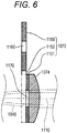
- FIG. 6 A schematic diagram of Fig. 6 is a cross-sectional view illustrating the gloss measurement diameter changing mechanism and the like.
- Schematic diagrams of Figs. 7 and 8 are front views illustrating the gloss measurement diameter changing mechanism and the like.
- the gloss measurement diameter changing mechanism 1073 includes, as illustrated in Figs. 6 to 8 , an aperture plate 1150, an aperture plate 1151, a movement mechanism 1152, and the like.
- the aperture plate 1150 and the aperture plate 1151 limit the light beam flux of the illumination light 1040.
- the movement mechanism 1152 moves the aperture plate 1150.
- the aperture plate 1150 is provided with an opening 1160.
- the aperture plate 1151 is provided with an opening 1170.
- a diameter of the opening 1160 is smaller than that of the opening 1170.
- a light beam flux limiting mechanism having a shape in which both or any one of the aperture plate 1150 and the aperture plate 1151 is not easily called a plate may be used.
- the aperture plate 1150 is adjacent to the aperture plate 1151 and limits the light beam flux of the illumination light 1040 at the substantially same position as the aperture plate 1151.
- the aperture plate 1150 and the aperture plate 1151 are perpendicular to the optical axis 1110.
- the aperture plate 1150 is moved by the movement mechanism 1152 to be located at the outside of the optical path of the illumination light 1040 as indicated by the solid line of Fig. 6 and illustrated in Fig. 7 or to be located onto the optical path of the illumination light 1040 as indicated by the one-dotted dash line of Fig. 6 or illustrated in Fig. 8 .
- the aperture plate 1151 is fixed on the optical path of the illumination light 1040.
- the movement mechanism 1152 generates a force of moving the aperture plate 1150 and transmits the force of moving the aperture plate 1150 to the aperture plate 1150.
- the force of moving the aperture plate 1150 is generated by an electromagnetic motor, an electromagnetic actuator, a piezoelectric actuator, or the like.
- the aperture plate 1150 When the aperture plate 1150 is located out of the optical path of the illumination light 1040, the aperture plate 1151 overlaps the lens 1074 when viewed from the extension direction of the optical axis 1110 and the illumination light 1040 passing through the gloss measurement diameter changing mechanism 1073 passes through the opening 1170.
- the opening 1170 forms the opening 1100 through which the illumination light 1040 passes and the diameter of the opening 1100 is determined by the diameter of the opening 1170.
- the aperture plate 1150 and the aperture plate 1151 overlap the lens 1074 when viewed from the extension direction of the optical axis 1110 and the illumination light 1040 passing through the gloss measurement diameter changing mechanism 1073 passes through the opening 1160 and the opening 1170.
- the opening 1160 and the opening 1170 form the opening 1100 through which the illumination light 1040 passes and the diameter of the opening 1100 is determined by the diameter of the relatively small opening 1160.
- the gloss measurement diameter changing mechanism 1073 changes the diameter of the opening 1100 in two levels by inserting the aperture plate 1150 into the optical path of the illumination light 1040 or extracting the aperture plate from the optical path of the illumination light 1040.
- the gloss measurement diameter changing mechanism 1073 may change the diameter of the opening 1100 in three or more levels.
- the gloss measurement diameter changing mechanism 1073 may continuously change the diameter of the opening 1100. For example, the diameter of the opening 1100 may be continuously changed by a diaphragm aperture.
- an opening angle of the light beam flux of the illumination light 1040 having passed through the opening 1100 is changed so that the diameter of the gloss measurement illumination target area is changed.
- the gloss measurement diameter is changed.
- the diameter of the opening 1100 is determined by the diameter of the opening 1170
- the diameter of the gloss measurement illumination target area becomes the standard diameter
- the gloss measurement diameter becomes the standard diameter.
- the size of the opening 1100 is determined by the size of the opening 1160
- the diameter of the gloss measurement illumination target area becomes the small diameter and the gloss measurement diameter becomes the small diameter.
- the diameter of the illumination target area may be changed in accordance with a method other than a change in diameter of the opening 1100.
- the gloss measurement diameter may be changed in accordance with a method other than a change in diameter of the gloss measurement illumination target area.
- the opening 1160 and the opening 1170 have an oval shape when viewed from the extension direction of the optical axis 1110.
- a short axis of the oval is included in a plane 1180 including the optical axis 1110 and the normal line 1120 of the illumination target face 1050.
- a long axis of the oval is perpendicular to the plane 1180.
- the gloss measurement illumination target area may have a circular shape.
- the shapes of the opening 1160 and the opening 1170 may be changed.
- the opening 1160 and the opening 1170 may have circular or rectangular shape when viewed from the extension direction of the optical axis 1111.
- the light receiving target area of the color measurement is circular in many cases.
- the shape of the gloss measurement illumination target area can match the shape of the light receiving target area of the color measurement and the shape of the gloss measurement target area can match the shape of the color measurement target area so that the gloss measurement target area can match the color measurement target area.
- the opening 1160 and the opening 1170 are circular, the illumination light 1040 is incident to the illumination target face 1050 from a direction forming an angle of 60° with respect to the normal line 1120 of the illumination target face 1050.
- the gloss measurement illumination target area has an oval shape in which a length of a long axis is two times a length of a short axis. Accordingly, the gloss measurement target area may match the color measurement target area.
- the diameter of the gloss measurement illumination target area is changed in accordance with a change in diameter of the opening 1100 through which the illumination light 1040 passes and the gloss measurement diameter is changed in accordance with a change in diameter of the gloss measurement illumination target area. More generally, the size of the gloss measurement illumination target area is changed in accordance with a change in size of the opening 1100 through which the illumination light 1040 passes and the size of the gloss measurement target area is changed in accordance with a change in size of the gloss measurement illumination target area. This general description is applied to a case where the diameter of the opening 1100 is not easily defined.
- the gloss measurement light receiving mechanism 1031 includes, as illustrated in Fig. 3 , a lens 1190, a mirror 1191, a light amount measurement instrument 1192, a barrel 1193, and the like.
- the lens 1190 converges the light beam flux of the reflected light 1041.
- the mirror 1191 reflects the reflected light 1041.
- the light amount measurement instrument 1192 outputs a signal depending on the light amount of the reflected light 1041.
- the reflection face 1200 of the mirror 1191 is directed toward a direction between a direction toward the illumination target face 1050 and a direction toward the light amount measurement instrument 1192.
- the lens 1190 exists between the illumination target face 1050 and the reflection face 1200.
- the reflected light 1041 advances along an optical axis 1210.
- the reflected light 1041 is generated by the regular reflection of the illumination light 1040 on the illumination target face 1050, is emitted from the illumination target face 1050 in a direction of a light receiving angle of 60°, passes through the lens 1190, is reflected by the mirror 1191, and is received by the light amount measurement instrument 1192.
- the direction of the light receiving angle of 60° is a direction which forms an angle of 60° with respect to the normal line 1120 of the illumination target face 1050.
- the light amount measurement instrument 1192 outputs a signal depending on the light amount of the reflected light 1041. A signal which is output from the light amount measurement instrument 1192 becomes a measurement result for the reflected light 1041.
- the reflected light 1041 passes through the lens 1190, the light beam flux of the reflected light 1041 is converged.
- the optical axis 1210 is bent.
- a first section 1220 of the optical axis 1210 illustrated in Fig. 5 is a section from the illumination target face 1050 to the reflection face 1200 and extends in the direction of the light receiving angle of 60°.
- a second section 1221 of the optical axis 1210 illustrated in Fig. 5 is a section from the reflection face 1200 to the light amount measurement instrument 1192 and extends in a direction different from the extension direction of the first section 1220.
- the optical axis 1210 is bent so that the reflected light 1041 advances along the first section 1220 and the second section 1221.
- the optical axis 1210 may not be bent.
- the optical system including the lens 1190 and the mirror 1191 may be replaced by a different optical system.
- the color measurement illumination mechanism 1032 includes, as illustrated in Figs. 3 and 4 , a light emitting mechanism 1230, a reflection mechanism 1231, and the like.
- the light emitting mechanism 1230 emits the light 1044, the light 1045, and the like.
- the reflection mechanism 1231 sets the light 1044 as the annular illumination light 1042.
- the color measurement illumination mechanism 1032 may be replaced by a different illumination mechanism.
- the light emitting mechanism 1230 includes, as illustrated in Figs. 3 and 4 , a straight tube type xenon lamp 1240, an integrating sphere 1241, a baffle 1242, and the like.
- the straight tube type xenon lamp 1240 emits light.
- the integrating sphere 1241 is used to obtain uniform light.
- the baffle 1242 is used to suppress non-uniform emission of light.
- a spherical space 1250 which is formed in the integrating sphere 1241 is defined by the inner face 1260 of the integrating sphere 1241.
- a round-hole-shaped light emitting opening 1251 which is formed in the integrating sphere 1241 is used to communicate the space 1250 and the outside of the integrating sphere 1241 with each other.
- the inner face 1260 includes a dispersion reflection face 1270. Desirably, the entire inner face 1260 becomes the dispersion reflection face 1270, but the inner face 1260 may be a slight face other than the dispersion reflection face 1270.
- the straight tube type xenon lamp 1240 emits light
- the light sequentially advances through the space 1250 and the light emitting opening 1251 so that the light is finally emitted to the outside of the integrating sphere 1241. While the light advances through the space 1250, the light is dispersed and reflected by the dispersion reflection face 1270 at least once. While the light advances through the space 1250, most of the light is repeatedly dispersed and reflected by the dispersion reflection face 1270. When the light is dispersed and reflected by the dispersion reflection face 1270 and is emitted from the light emitting opening 1251, the light is uniformly emitted from the light emitting mechanism 1230.
- the light emitting mechanism 1230 substantially has a vertical light distribution characteristic according to Lambert's cosine law.
- the intensity of the light emitted in a direction forming an angle ⁇ with respect to a reference axis 1280 is proportional to a cosine ⁇ of the angle ⁇ .
- a main part of the straight tube type xenon lamp 1240 and a main part of the baffle 1242 exist in the space 1250.
- the baffle 1242 exists between the straight tube type xenon lamp 1240 and the light emitting opening 1251.
- the light beam which is directly directed from the straight tube type xenon lamp 1240 toward the light emitting opening 1251 is shielded by the baffle 1242. Accordingly, it is possible to suppress the light emitted from the straight tube type xenon lamp 1240 from being emitted from the light emitting opening 1251 without the dispersion and the reflection by the dispersion reflection face 1270. As a result, stray light is suppressed and color measurement accuracy is improved.
- the light emitting mechanism 1230 may be changed to a different light emitting mechanism.
- FIG. 9 A schematic diagram of Fig. 9 is a perspective view illustrating an arrangement of planar reflection faces.
- the reflection mechanism 1231 illustrated in Figs. 3 and 4 includes, as illustrated in Fig. 9 , ten planar reflection faces 1340.
- Each of the ten planar reflection faces 1340 is a mirror face and reflects the light 1044.
- Ten planar reflection faces 1340 are arranged about the reference axis 1280 to be distributed in a circumferential direction 1350 surrounding the reference axis 1280.
- Ten planar reflection faces 1340 are directed toward an inner radial side 1351 which becomes closer to the reference axis 1280.
- Ten planar reflection faces 1340 are arranged so that the light 1044 becomes incident light and the reflected light becomes the annular illumination light 1042.
- the annular illumination light 1042 is incident to the illumination target face 1050 from a direction of an illumination angle of 45°.
- the direction of the illumination angle of 45° is a direction which forms an angle of 45° with respect to the normal line 1120 of the illumination target face 1050.
- the illumination target face 1050 is illuminated from two or more directions distributed in the circumferential direction 1350.
- the reflected light 1043 is not largely changed by the direction of the illumination target face 1050 even when the illumination target face 1050 has an anisotropic reflection characteristic and thus color measurement stability is improved.
- a color measurement illumination target area illuminated by the annular illumination light 1042 overlaps a gloss measurement illumination target area illuminated by the illumination light 1040. More desirably, the position of the color measurement illumination target area illuminated by the annular illumination light 1042 matches the position of the gloss measurement illumination target area illuminated by the illumination light 1040. Accordingly, the position of the gloss measurement target area can be indicated by the annular illumination light 1042 for the color measurement in the gloss measurement and the position of the color measurement target area can be indicated by the illumination light 1040 for the gloss measurement in the color measurement.
- the straight tube type xenon lamp 1240 is desirably replaced by a light source continuously emitting light.
- Ten planar reflection faces 1340 may be changed to nine or less or eleven or more planar reflection faces.
- Ten planar reflection faces 1340 may be changed to a cylindrical reflection face, a rotary oval reflection face, or the like.
- the color measurement light receiving mechanism 1033 includes, as illustrated in Fig. 3 , a mirror 1370, a color measurement diameter changing mechanism 1371, a spectral measurement instrument 1372, a barrel 1373, and the like.
- the color measurement light receiving mechanism 1033 receives the reflected light 1043 generated by a reflection of the annular illumination light 1042 on the light receiving target area of the illumination target face 1050.
- the mirror 1370 reflects the reflected light 1043.
- the color measurement diameter changing mechanism 1371 changes the color measurement diameter.
- the spectral measurement instrument 1372 outputs a signal depending on the light amount of each wavelength component of the reflected light 1043.
- the barrel 1373 holds the mirror 1370, the color measurement diameter changing mechanism 1371, and the like.
- the barrel 1373 is integrated with the barrel 1075 and the barrel 1193 to form a barrel assembly.
- the mirror 1370 exists on the normal line 1120 of the illumination target face 1050.
- a reflection face 1380 of the mirror 1370 is directed toward a direction between a direction toward the illumination target face 1050 and a direction toward the spectral measurement instrument 1372.
- a lens 1390 of the color measurement diameter changing mechanism 1371 exists between the reflection face 1380 and the spectral measurement instrument 1372.
- the reflected light 1043 advances along an optical axis 1400.
- the reflected light 1043 is generated by a reflection of the annular illumination light 1042 on the illumination target face 1050, is emitted from the illumination target face 1050 in a direction of a light receiving angle of 0°, is reflected by the mirror 1370, passes through the lens 1390, and is received by the spectral measurement instrument 1372.
- the direction of the light receiving angle of 0° is a direction that forms an angle of 0° with respect to the normal line 1120 of the illumination target face 1050.
- the spectral measurement instrument 1372 outputs a signal depending on the light amount of each wavelength component of the reflected light 1043.
- a signal output from the spectral measurement instrument 1372 becomes a measurement result for the reflected light 1043.
- the optical axis 1400 is bent.
- the reflected light 1043 passes through the lens 1390, the light beam flux of the reflected light 1043 is converged.
- a first section 1410 of the optical axis 1400 illustrated in Fig. 5 is a section from the illumination target face 1050 to the reflection face 1380 and extends in the direction of the light receiving angle of 0°.
- a second section 1411 of the optical axis 1400 illustrated in Fig. 5 is a section from the reflection face 1380 to the spectral measurement instrument 1372 and extends in a direction different from the extension direction of the first section 1410.
- the optical axis 1400 is bent so that the reflected light 1043 advances along the first section 1410 and the second section 1411.
- the optical axis 1400 may not be bent.
- the optical system including the mirror 1370 may be replaced by a different optical system.
- the spectral measurement instrument 1372 may be replaced by a mechanism that directly reads tristimulus values.
- FIG. 10 A schematic diagram of Fig. 10 is a cross-section illustrating the color measurement diameter changing mechanism and the like.
- the color measurement diameter changing mechanism 1371 includes, as illustrated in Fig. 10 , the lens 1390, a parallel movement mechanism 1391, a limit switch 1392, a limit switch 1393, and the like.
- the lens 1390 converges the light beam flux of the reflected light 1043.
- the parallel movement mechanism 1391 moves the lens 1390 in parallel.
- the limit switch 1392 and the limit switch 1393 detect the position of the lens holder 1420.
- the parallel movement mechanism 1391 includes the lens holder 1420, a guide cylinder 1421, a knob 1422, and the like.
- the lens holder 1420 holds the lens 1390.
- the guide cylinder 1421 guides the lens holder 1420.
- the knob 1422 transmits an applied force to the lens holder 1420.
- the knob 1422 may be replaced by a different operation member.
- a driving mechanism which generates a part or the entirety of a force transmitted to the lens holder 1420 may be provided.
- the lens holder 1420 is inserted into a guide hole 1430 formed in the guide cylinder 1421 and is slidable in the extension direction of the guide hole 1430.
- the extension direction of the guide hole 1430 matches the extension direction of the optical axis 1400. Accordingly, the movement direction of the lens 1390 is regulated in the extension direction of the optical axis 1400 and the lens 1390 is guided in the extension direction of the optical axis 1400.
- a force is applied to the knob 1422, the applied force is transmitted to the lens holder 1420 so that the lens 1390 and the lens holder 1420 move together in parallel to the optical axis 1400.
- the lens 1390 is moved in parallel by the parallel movement mechanism 1391 so as to be near the spectral measurement instrument 1372 as indicated by the solid line of Fig. 10 or near the illumination target face 1050 as indicated by the two-dotted dash line of Fig. 10 .
- the parallel movement mechanism 1391 moves the lens 1390 in parallel along the optical axis 1400, the position of the lens 1390 is changed in two levels.
- the parallel movement mechanism 1391 may change the position of the lens 1390 in three or more levels.
- the parallel movement mechanism 1391 may continuously change the position of the lens 1390.
- the opening angle of the light beam flux of the reflected light 1043 to pass through the lens 1390 is changed and the diameter of the light receiving target area in the color measurement is changed.
- the diameter of the light receiving target area of the color measurement is changed, the color measurement diameter is changed.
- the diameter of the light receiving target area of the color measurement becomes the standard diameter and the color measurement diameter becomes the standard diameter.
- the diameter of the light receiving target area of the color measurement becomes the small diameter and the color measurement diameter becomes the small diameter.
- the limit switch 1392 detects a state where the lens holder 1420 is near the spectral measurement instrument 1372.
- the limit switch 1393 detects a state where the lens holder 1420 is near the illumination target face 1050.
- the lens 1390 is near the spectral measurement instrument 1372 so that the color measurement diameter becomes the standard diameter.
- the lens 1390 is near the illumination target face 1050 so that the color measurement diameter becomes the small diameter.
- the color measurement diameter is determined by the position of the lens holder 1420 and the limit switch 1392 and the limit switch 1393 output a detection result for the position of the lens holder 1420 for determining the color measurement diameter.
- a position of a constituent other than the lens holder 1420 may be detected.
- the position of the lens 1390, the knob 1422, or the like may be detected.
- the position may be detected by a detection mechanism other than the limit switch 1392 and the limit switch 1393.
- the position may be detected by a laser displacement gauge.
- the color measurement diameter is changed in accordance with a change in diameter of the light receiving target area of the color measurement. More generally, the size of the color measurement target area is changed in accordance with a change in size of the light receiving target area of the color measurement. This general description is applied to a case where the light receiving target area of the color measurement has a shape in which a diameter is not easily defined.
- the correction light receiving mechanism 1034 includes, as illustrated in Fig. 3 , a mirror 1440, an optical fiber 1441, a spectral measurement instrument 1442, and the like.
- the spectral measurement instrument 1442 is common to the spectral measurement instrument 1372.
- the light 1045 advances along the optical axis 1465.
- the light 1045 is emitted from the light emitting opening 1251 in a direction forming an angle of 0° with respect to the reference axis 1280, is reflected by the mirror 1440, is guided to the optical fiber 1441, and is received by the spectral measurement instrument 1442.
- the spectral measurement instrument 1442 outputs a signal depending on the light amount of each wavelength component of the light 1045.
- FIG. 11 A block diagram of Fig. 11 illustrates a gloss colorimeter.
- the control mechanism 1011 includes, as illustrated in Fig. 11 , a built-in computer 1480, a light emitting circuit 1481, a monitor 1482, and the like.
- the built-in computer 1480 controls the light emitting circuit 1481, the monitor 1482, the measurement instrument 1010, and the like by performing an installed firmware so that a process is performed in accordance with the firmware. A part or the entirety of the process performed by the built-in computer 1480 may be performed by hardware not performing a program.
- the light emitting circuit 1481 supplies electric power to the halogen lamp 1070 and the straight tube type xenon lamp 1240.
- the monitor 1482 displays information.
- the built-in computer 1480 controls an illumination of the illumination light 1040 by controlling the supply of the electric power from the light emitting circuit 1481 to the halogen lamp 1070 and controls an illumination of the annular illumination light 1042 by controlling the supply of the electric power from the light emitting circuit 1481 to the straight tube type xenon lamp 1240.
- the built-in computer 1480 acquires a measurement result from the light amount measurement instrument 1192 and acquires a measurement result from the spectral measurement instrument 1372 and the spectral measurement instrument 1442.
- the built-in computer 1480 obtains gloss information from the measurement result acquired from the light amount measurement instrument 1192 and obtains color measurement information from the measurement result acquired from the spectral measurement instrument 1372.
- the built-in computer 1480 performs a correction reflecting the measurement result acquired from the spectral measurement instrument 1442 when the color measurement information is obtained. Accordingly, it is possible to reduce an influence of a change in light emitted from the light emitting mechanism 1230 with respect to the color measurement information.
- the gloss information includes gloss and the like.
- the color measurement information includes a spectrum, a color gamut, and the like.
- the built-in computer 1480 displays the gloss information and the color measurement information obtained in this way on the monitor 1482.
- the built-in computer 1480 acquires a detection result from the limit switch 1392 and the limit switch 1393.
- the built-in computer 1480 moves the aperture plate 1150 to the outside of the optical path of the illumination light 1040 by the movement mechanism 1152.
- the built-in computer 1480 moves the aperture plate 1150 onto the optical path of the illumination light 1040 by the movement mechanism 1152. Accordingly, an interlocking mechanism 1490 changing the gloss measurement diameter by the gloss measurement instrument 1020 in accordance with a detection result of the limit switch 1392 and the limit switch 1393 so that the gloss measurement diameter is changed in synchronization with a change in color measurement diameter is formed.
- the gloss measurement diameter is changed to the standard diameter in synchronization with a change in color measurement diameter.
- the gloss measurement diameter is changed to the small diameter in synchronization with a change in color measurement diameter.
- the gloss measurement diameter matches the color measurement diameter in synchronization with the color measurement diameter.
- the interlocking mechanism 1490 since there is no need to cause the gloss measurement diameter to match the color measurement diameter, it is possible to prevent an erroneous measurement caused when the gloss measurement diameter does not match the color measurement diameter. Accordingly, the gloss measurement target area and the color measurement target area are appropriately set. Further, since an operation necessary for causing the gloss measurement diameter to match the color measurement diameter is reduced, measurement efficiency is improved.
- a correction reflecting the measurement result acquired from the spectral measurement instrument 1372 may be performed when the gloss information is obtained from the measurement result acquired by the light amount measurement instrument 1192.
- an influence of the color of the illumination target face 1050 with respect to the gloss information is reduced.
- the color of the illumination target face 1050 is white
- the inner dispersion light becomes stronger compared to a case where the color of the illumination target face 1050 is black. Accordingly, there is a strong tendency that gloss which is stronger than real gloss is measured.
- the reflection of the measurement result acquired from the spectral measurement instrument 1372 By the reflection of the measurement result acquired from the spectral measurement instrument 1372, a difference from real gloss is suppressed.
- the built-in computer 1480 performs the color measurement by the color measurement instrument 1021, acquires a measurement result from the color measurement instrument 1021, and derives color measurement information from the measurement result.
- the built-in computer 1480 performs the gloss measurement by the gloss measurement instrument 1020 while driving color measurement information from the measurement result.
- the reflected light 1041 is received by a single-cell sensor having light sensitivity based on JIS-Z8741 and a single signal is output in response to the light amount of the reflected light 1041.
- a single-cell sensor having light sensitivity based on JIS-Z8741 and a single signal is output in response to the light amount of the reflected light 1041.
- multiple signals are output in response to the light amount of the wavelength component of the reflected light 1043. For this reason, a time necessary to derive the color measurement information is longer than a time necessary for a process of deriving the gloss information.
- a second embodiment relates to a gloss measurement diameter changing mechanism to be used instead of the gloss measurement diameter changing mechanism of the first embodiment.
- a technology used in the other embodiment may be used in the second embodiment.
- FIG. 12 A schematic diagram of Fig. 12 is a cross-sectional view illustrating the gloss measurement diameter changing mechanism and the like.
- Schematic diagrams of Figs. 13 and 14 are front views illustrating the gloss measurement diameter changing mechanism and the like.
- the gloss measurement diameter changing mechanism 2000 includes, as illustrated in Figs. 12 to 14 , an aperture plate 2010, a movement mechanism 2011, and the like.
- the aperture plate 2010 limits the light beam flux of the illumination light 1040.
- the movement mechanism 2011 moves the aperture plate 2010.
- An area 2020 of the aperture plate 2010 is provided with an opening 2030.
- An area 2021 of the aperture plate 2010 is provided with an opening 2031.
- the diameter of the opening 2030 is smaller than that of the opening 2031.
- a light beam flux limiting mechanism in which the aperture plate 2010 is not easily called a plate may be used.
- the aperture plate 2010 is perpendicular to the optical axis 1110.
- the aperture plate 2010 is moved by the movement mechanism 2011 to be located at a position in which the area 2020 indicated by the solid line of Fig. 12 and illustrated in Fig. 13 is located at the outside of the optical path of the illumination light 1040 and the area 2021 is located on the optical path of the illumination light 1040 or a position in which the area 2020 indicated by the one-dotted dash line illustrated in Fig. 12 and illustrated in Fig. 14 is located on the optical path of the illumination light 1040 and the area 2021 is located at the outside of the optical path of the illumination light 1040.
- the movement mechanism 2011 generates a force of moving the aperture plate 2010 and transmits the force of moving the aperture plate 2010 to the aperture plate 2010.
- the force of moving the aperture plate 2010 is generated by an electromagnetic motor, an electromagnetic actuator, a piezoelectric actuator, or the like.
- the area 2021 overlaps the lens 1074 when viewed from the extension direction of the optical axis 1110 and the illumination light 1040 passing through the gloss measurement diameter changing mechanism 2000 passes through the opening 2031.
- the opening 2031 forms an opening through which the illumination light 1040 passes and the diameter of the opening through which the illumination light 1040 passes is determined by the diameter of the opening 2031.
- the area 2020 When the area 2020 is located on the optical path of the illumination light 1040 and the area 2021 is located at the outside of the optical path of the illumination light 1040, the area 2020 overlaps the lens 1074 when viewed from the extension direction of the optical axis 1110 and the illumination light 1040 passing through the gloss measurement diameter changing mechanism 2000 passes through the opening 2030.
- the opening 2030 forms an opening through which the illumination light 1040 passes and the diameter of the opening through which the illumination light 1040 passes is determined by the diameter of the opening 2030.
- the gloss measurement diameter changing mechanism 2000 changes the diameter of the opening through which the illumination light 1040 passes in two levels by changing an area on the optical path.
- the diameter of the opening through which the illumination light 1040 passes is changed.
- the gloss measurement diameter is changed.
- the diameter of the opening through which the illumination light 1040 passes is determined by the diameter of the opening 2031
- the diameter of the gloss measurement illumination target area becomes the standard diameter
- the gloss measurement diameter becomes the standard diameter.
- the diameter of the opening through which the illumination light 1040 passes is determined by the diameter of the opening 2030
- the diameter of the gloss measurement illumination target area becomes the small diameter and the gloss measurement diameter becomes the small diameter.
- a third embodiment relates to a gloss measurement diameter changing mechanism to be used instead of the gloss measurement diameter changing mechanism of the first embodiment.
- a technology used in the other embodiment may be used in the third embodiment.
- FIG. 15 A schematic diagram of Fig. 15 is a cross-sectional view illustrating the gloss measurement diameter changing mechanism and the like.
- the gloss measurement diameter changing mechanism 3000 includes, as illustrated in Fig. 15 , an aperture plate 3010, a movement mechanism 3011, and the like.
- the aperture plate 3010 limits the light beam flux of the illumination light 1040.
- the movement mechanism 3011 moves the aperture plate 3010.
- the aperture plate 3010 is provided with an opening 3020.
- the aperture plate 3010 is perpendicular to the optical axis 1110.
- a light beam flux limiting mechanism in which the aperture plate 3010 is not easily called a plate may be used.
- the aperture plate 3010 is on the optical path of the illumination light 1040 and is moved by the movement mechanism 3011 to be located near the halogen lamp 1070 or the illumination target face 1050.
- the movement mechanism 3011 generates a force of moving the aperture plate 3010 and transmits the force of moving the aperture plate 3010 to the aperture plate 3010.
- the force of moving the aperture plate 3010 is generated by an electromagnetic motor, an electromagnetic actuator, a piezoelectric actuator, or the like.
- the aperture plate 3010 overlaps the lens 1074 when viewed from the extension direction of the optical axis 1110.
- the illumination light 1040 which passes through the gloss measurement diameter changing mechanism 3000 passes through the opening 3020.
- the opening 3020 forms an opening through which the illumination light 1040 passes.
- the position of the opening 3020 is changed in two levels.
- the movement mechanism 3011 may change the position of the opening 3020 in three or more levels.
- the movement mechanism 3011 may continuously change the position of the opening 3020.
- the opening angle of the light beam flux of the illumination light 1040 having passed through the opening 3020 is changed and the diameter of the gloss measurement illumination target area is changed.
- the gloss measurement diameter is changed.
- the aperture plate 3010 is near the halogen lamp 1070, the opening angle of the light beam flux of the illumination light 1040 having passed through the opening 3020 relatively increases so that the diameter of the gloss measurement illumination target area becomes the standard diameter and the gloss measurement diameter becomes the standard diameter.
- the opening angle of the light beam flux of the illumination light 1040 having passed through the opening 3020 relatively decreases so that the diameter of the gloss measurement illumination target area becomes the small diameter and the gloss measurement diameter becomes the small diameter.
- a fourth embodiment relates to an interlocking mechanism to be used instead of the interlocking mechanism of the first embodiment.
- the color measurement diameter is manually changed between the standard diameter and the small diameter and the gloss measurement diameter is automatically changed between the standard diameter and the small diameter in synchronization with a change in color measurement diameter.
- the gloss measurement diameter is manually changed between the standard diameter and the small diameter and the color measurement diameter is automatically changed between the standard diameter and the small diameter in synchronization with a change in gloss measurement diameter.
- a technology used in the other embodiment may be used in the fourth embodiment.
- a schematic diagram of Fig. 16 is a cross-sectional view illustrating the measurement instrument equipped with the interlocking mechanism of the fourth embodiment.
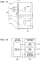
- a schematic diagram of Fig. 17 is a front view illustrating the gloss measurement diameter changing mechanism and the like.
- the gloss measurement diameter changing mechanism 4000 includes, as illustrated in Figs. 16 and 17 , an aperture plate 4010, an aperture plate 4011, a movement mechanism 4012, a limit switch 4013, a limit switch 4014, and the like.
- the aperture plate 4010 and the aperture plate 4011 are respectively the same as the aperture plate 1150 and the aperture plate 1151 of the first embodiment and limit the light beam flux of the illumination light 1040.
- the movement mechanism 4012 moves the aperture plate 4010.
- the limit switch 4013 and the limit switch 4014 detect the position of the aperture plate 4010.
- the movement mechanism 4012 includes, a guide rail 4020, a knob 4021, and the like.
- the guide rail 4020 guides the aperture plate 4010.
- the knob 4021 transmits an applied force to the aperture plate 4010.
- the aperture plate 4010 is provided with an opening 4030.
- the aperture plate 4011 is provided with an opening 4031.
- the diameter of the opening 4030 is smaller than that of the opening 4031.
- the aperture plate 4010 is moved by the movement mechanism 4012 to be located at the outside of the optical path of the illumination light 1040 or to be located onto the optical path of the illumination light 1040.
- the aperture plate 4011 is fixed onto the optical path of the illumination light 1040.
- the aperture plate 4010 is coupled to the guide rail 4020 and is slidable in the extension direction of the guide rail 4020. Accordingly, the extension direction of the aperture plate 4010 is regulated in the extension direction of the guide rail 4020 and the aperture plate 4010 is guided in the extension direction of the guide rail 4020. When a force is applied to the knob 4021, the applied force is transmitted to the aperture plate 4010 and the aperture plate 4010 moves in the extension direction of the guide rail 4020.
- the opening 4031 forms an opening through which the illumination light 1040 passes and the diameter of the opening through which the illumination light 1040 passes is determined by the diameter of the opening 4031.
- the opening 4030 and the opening 4031 form an opening through which the illumination light 1040 passes and the diameter of the opening through which the illumination light 1040 passes is determined by the diameter of the relatively small opening 4030.
- the gloss measurement diameter changing mechanism 4000 changes the diameter of the opening through which the illumination light 1040 passes in two levels by inserting the aperture plate 4010 into the optical path of the illumination light 1040 or extracting the aperture plate from the optical path of the illumination light 1040.
- the diameter of the opening through which the illumination light 1040 passes is changed.
- the gloss measurement diameter is changed.
- the diameter of the opening through which the illumination light 1040 passes is determined by the size of the opening 4031
- the diameter of the gloss measurement illumination target area becomes the standard diameter
- the gloss measurement diameter becomes the standard diameter.
- the diameter of the opening through which the illumination light 1040 passes is determined by the size of the opening 4030
- the diameter of the gloss measurement illumination target area becomes the small diameter and the gloss measurement diameter becomes the small diameter.
- the limit switch 4013 detects a state where the aperture plate 4010 is located at the outside of the optical path of the illumination light 1040.
- the limit switch 4014 detects a state where the aperture plate 4010 is located on the optical path of the illumination light 1040.
- the gloss measurement diameter becomes the standard diameter.
- the gloss measurement diameter becomes the small diameter.
- the gloss measurement diameter is determined by the position of the aperture plate 4010 and the limit switch 4013 and the limit switch 4014 output a detection result for the position of the aperture plate 4010 determining the gloss measurement diameter.
- a position of a constituent other than the aperture plate 4010 may be detected.
- the position of the knob 4021 or the like may be detected.
- the position may be detected by a detection mechanism other than the limit switch 4013 and the limit switch 4014.
- the position may be detected by a laser displacement gauge.
- the color measurement diameter changing mechanism 4040 includes, as illustrated in Fig. 16 , a lens 4050, a parallel movement mechanism 4051, and the like.
- the lens 4050 is the same as the lens 1390 of the first embodiment and converges the light beam flux of the reflected light 1043.
- the parallel movement mechanism 4051 moves the lens 4050 in parallel.
- the parallel movement mechanism 4051 includes a lens holder 4060, a guide cylinder 4061, a driving mechanism 4062, and the like.
- the lens holder 4060 is the same as the lens holder 1420 of the first embodiment and holds the lens 4050.
- the guide cylinder 4061 is the same as the guide cylinder 1421 of the first embodiment and guides the lens holder 4060.
- the driving mechanism 4062 transmits a generated force to the lens holder 4060.
- the lens holder 4060 is inserted into a guide hole 4070 formed in the guide cylinder 4061 and is slidable in the extension direction of the guide hole 4070.
- the extension direction of the guide hole 4070 matches the extension direction of the optical axis 1400. Accordingly, the movement direction of the lens 4050 is regulated in the extension direction of the optical axis 1400 and the lens 4050 is guided in the extension direction of the optical axis 1400.
- the driving mechanism 4062 generates a force of moving the lens holder 4060 and transmits the force of moving the lens holder 4060 to the lens holder 4060.
- the force of moving the lens holder 4060 is generated by an electromagnetic motor, an electromagnetic actuator, a piezoelectric actuator, or the like. When the driving mechanism 4062 transmits a force to the lens holder 4060, the lens 4050 and the lens holder 4060 move together along the optical axis 1400 in parallel.
- the lens 4050 is moved in parallel by the parallel movement mechanism 4051 to be located near the spectral measurement instrument 1372 indicated by the solid line of Fig. 16 or the illumination target face 1050 indicated by the two-dotted dash line of Fig. 16 .
- the parallel movement mechanism 4051 moves the lens 4050 along the optical axis 1400 in parallel, the position of the lens 4050 is changed in two levels.
- the lens 4050 When the lens 4050 is moved along the optical axis 1400 in parallel, the diameter of the light receiving target area of the color measurement is changed. When the diameter of the light receiving target area of the color measurement is changed, the color measurement diameter is changed.
- the diameter of the light receiving target area of the color measurement becomes the standard diameter and the color measurement diameter becomes the standard diameter.
- the diameter of the light receiving target area of the color measurement becomes the small diameter and the color measurement diameter becomes the small diameter.
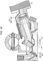
- FIG. 18 A block diagram of Fig. 18 illustrates an interlocking mechanism.
- a built-in computer 4080 acquires, as illustrated in Fig. 18 , a detection result from the limit switch 4013 and the limit switch 4014.
- the built-in computer 4080 moves the lens 4050 to a position near the spectral measurement instrument 1372 by the parallel movement mechanism 4051.
- the built-in computer 4080 moves the lens 4050 to a position near the illumination target face 1050 by the parallel movement mechanism 4051. Accordingly, an interlocking mechanism 4090 changing the color measurement diameter by the color measurement instrument 4074 in accordance with a detection result so that the color measurement diameter changes in synchronization with the gloss measurement diameter is formed.
- the color measurement diameter is changed to the standard diameter in synchronization with a change in gloss measurement diameter.
- the gloss measurement diameter is changed to the small diameter, the color measurement diameter is changed to the small diameter in synchronization with a change in gloss measurement diameter.
- the color measurement diameter matches the gloss measurement diameter in synchronization with the gloss measurement diameter.
- a fifth embodiment relates to an interlocking mechanism to be used instead of the gloss measurement interlocking mechanism of the first embodiment.
- the color measurement diameter is manually changed between the standard diameter and the small diameter and the gloss measurement diameter is automatically changed between the standard diameter and the small diameter in synchronization with a change in color measurement diameter.
- the gloss measurement diameter and the color measurement diameter are changed between the standard diameter and the small diameter in response to an operation of changing the measurement diameter.
- a technology used in the other embodiment may be used in the fifth embodiment.
- FIG. 19 A schematic diagram of Fig. 19 is a cross-sectional view illustrating the measurement instrument equipped with the interlocking mechanism of the fifth embodiment.
- a block diagram of Fig. 20 illustrates an interlocking mechanism.
- a gloss measurement diameter changing mechanism 5000 illustrated in Fig. 19 is the same as the gloss measurement diameter changing mechanism 1073 of the first embodiment.
- a color measurement diameter changing mechanism 5010 illustrated in Fig. 19 is the same as the color measurement diameter changing mechanism 4000 of the fourth embodiment.
- a built-in computer 5020 acquires, as illustrated in Fig. 20 , a detection result for an operation performed by a operation unit 5021.
- the built-in computer 5020 moves the aperture plate 5041 to the outside of the optical path of the illumination light 1040 by a movement mechanism 5040 constituting the gloss measurement diameter changing mechanism 5000 and moves a lens 5061 to a positron near the spectral measurement instrument 1372 by a parallel movement mechanism 5060 constituting the color measurement diameter changing mechanism 5010.
- the built-in computer 5020 moves the aperture plate 5041 onto the optical path of the illumination light 1040 by the movement mechanism 5040 and moves the lens 5061 to a position near the illumination target face 1050 by the parallel movement mechanism 5060. Accordingly, an interlocking mechanism 5090 which changes the gloss measurement diameter by the gloss measurement instrument 5080 and changes the color measurement diameter by the color measurement instrument 5081 in accordance with a detection result for an operation of changing the measurement diameter is formed.
- the operation unit 5021 is a switch, a touch panel, or the like and outputs a detection result for an operation of the gloss colorimeter.
- the operation unit may be replaced by a different detection mechanism.
- the operation unit may be replaced by a communication unit which communicates with a device other than the gloss colorimeter and detects a detection result for an operation of the device.
- the device is, for example, a remote controller, a mobile communication terminal, a personal computer, or the like.
- a sixth embodiment relates to an independent changing mechanism to be used instead of the interlocking mechanism of the fifth embodiment.
- the gloss measurement diameter and the color measurement diameter are changed between the standard diameter and the small diameter in response to an operation of changing the measurement diameter.
- the independent changing mechanism of the sixth embodiment the gloss measurement diameter is changed between the standard diameter and the small diameter and the color measurement diameter is changed between the standard diameter and the small diameter independently from the gloss measurement diameter.
- FIG. 21 A block diagram of Fig. 21 illustrates an independent changing mechanism.
- the movement mechanism 5040 moves the aperture plate 5041 to the outside of the optical path of the illumination light 1040.
- the movement mechanism 5040 moves the aperture plate 5041 onto the optical path of the illumination light 1040.
- the parallel movement mechanism 5060 moves the lens 5061 to a position near the spectral measurement instrument 1372.
- the parallel movement mechanism 5060 moves the lens 5061 to a position near the illumination target face 1050. Accordingly, an independent changing mechanism 6010 is formed.
Landscapes
- Physics & Mathematics (AREA)
- Spectroscopy & Molecular Physics (AREA)
- General Physics & Mathematics (AREA)
- Analytical Chemistry (AREA)
- Health & Medical Sciences (AREA)
- Life Sciences & Earth Sciences (AREA)
- Chemical & Material Sciences (AREA)
- Biochemistry (AREA)
- General Health & Medical Sciences (AREA)
- Immunology (AREA)
- Pathology (AREA)
- Theoretical Computer Science (AREA)
- Mathematical Physics (AREA)
- Engineering & Computer Science (AREA)
- Spectrometry And Color Measurement (AREA)
- Investigating Or Analysing Materials By Optical Means (AREA)
Abstract
Description
- The present invention relates to a surface characteristic measurement device.
- When surface characteristics such as gloss, color, haze, and a film thickness of a sample are measured, it is desirable to change a measurement diameter depending on the sample. For example, when the surface characteristics of the sample are not uniform, it is desirable to relatively increase the measurement diameter. On the other hand, when the sample is small or has a curved surface, it is desirable to relatively decrease the measurement diameter.
- Meanwhile, there is proposed a surface characteristic measurement device capable of measuring both gloss and a reflection characteristic other than the gloss.
Patent Literature 1 discloses an example thereof. - Patent Literature 1:
JP 2005-24562 A - In the conventional surface characteristic measurement device capable of measuring both the gloss and the reflection characteristic other than the gloss, a measurement diameter cannot be changed and thus a gloss measurement target area and a reflection characteristic measurement target area cannot be appropriately set. For this reason, a measurer who wants to appropriately set the gloss measurement target area and the reflection characteristic measurement target area needs to prepare a glossmeter and a reflection characteristic measurement device and change a device to be used depending on the sample. Such a change in device is complex.
- The present invention has been made to solve this problem. An object of the present invention is to measure both gloss and a reflection characteristic by one surface characteristic measurement device and to appropriately set a gloss measurement target area and a reflection characteristic measurement target area.
- In the surface characteristic measurement device, the gloss measurement instrument and the reflection characteristic measurement instrument are integrated with each other. The gloss measurement instrument illuminates an illumination target face by first illumination light, receives first reflected light generated by a regular reflection of the first illumination light on the illumination target face, and outputs a measurement result for the first reflected light. The size of the gloss measurement target area can be changed. The reflection characteristic measurement instrument illuminates an illumination target face by second illumination light, receives second reflected light generated by a reflection of the second illumination light on the illumination target face, and outputs a measurement result for the second reflected light. The size of the reflection characteristic measurement target area can be changed.
- Since one surface characteristic measurement device can measure both gloss and a reflection characteristic, a gloss measurement target area and a reflection characteristic measurement target area are appropriately set.
- These and other objects, features, aspects, and advantages of the present invention will become more apparent by the following detailed description of the present invention in conjunction with the accompanying drawings.
-
-
Fig. 1 is a schematic diagram illustrating a gloss colorimeter of a first embodiment. -
Fig. 2 is a bottom view illustrating a measurement instrument of the first embodiment. -
Fig. 3 is a cross-sectional view illustrating the measurement instrument of the first embodiment. -
Fig. 4 is a longitudinal sectional view illustrating the measurement instrument of the first embodiment. -
Fig. 5 is a perspective view illustrating an optical axis and the like of the first embodiment. -
Fig. 6 is a cross-sectional view illustrating a gloss measurement diameter changing mechanism and the like of the first embodiment. -
Fig. 7 is a front view illustrating the gloss measurement diameter changing mechanism and the like of the first embodiment. -
Fig. 8 is a front view illustrating the gloss measurement diameter changing mechanism and the like of the first embodiment. -
Fig. 9 is a perspective view illustrating an arrangement of a planar reflection face of the first embodiment. -
Fig. 10 is a cross-sectional view illustrating a color measurement diameter changing mechanism and the like of the first embodiment. -
Fig. 11 is a block diagram illustrating the gloss colorimeter of the first embodiment. -
Fig. 12 is a cross-sectional view illustrating a gloss measurement diameter changing mechanism and the like of a second embodiment. -
Fig. 13 is a front view illustrating the gloss measurement diameter changing mechanism and the like of the second embodiment. -
Fig. 14 is a front view illustrating the gloss measurement diameter changing mechanism and the like of the second embodiment. -
Fig. 15 is a cross-sectional view illustrating a gloss measurement diameter changing mechanism and the like of a third embodiment. -
Fig. 16 is a cross-sectional view illustrating a measurement instrument of a fourth embodiment. -
Fig. 17 is a cross-sectional view illustrating a gloss measurement diameter changing mechanism and the like of the fourth embodiment. -
Fig. 18 is a block diagram illustrating an interlocking mechanism of the fourth embodiment. -
Fig. 19 is a cross-sectional view illustrating a measurement instrument of a fifth embodiment. -
Fig. 20 is a block diagram illustrating an interlocking mechanism of the fifth embodiment. -
Fig. 21 is a block diagram illustrating an independent changing mechanism of a sixth embodiment. - A first embodiment relates to a gloss colorimeter.
- A schematic diagram of
Fig. 1 illustrates a gloss colorimeter of the first embodiment. - A
gloss colorimeter 1000 illustrated inFig. 1 serves as a glossmeter and a spectral colorimeter and measures gloss and spectral reflectance of a sample. A reflection characteristic other than the spectral reflectance may be measured. For example, a color gamut may be measured. That is, the spectral colorimeter function of thegloss colorimeter 1000 maybe changed to a function of a reflection characteristic measurement device other than the spectral colorimeter so that thegloss colorimeter 1000 is changed to a surface characteristic measurement device serving as a glossmeter and a reflection characteristic measurement device. For example, the spectral colorimeter function of thegloss colorimeter 1000 may be changed to a color measurement instrument function. - The gloss measurement is performed under a geometry in which an illumination angle and a light receiving angle become 60°. The color measurement is performed under a geometry in which an illumination angle becomes 45° and a light receiving angle becomes 0°. In the gloss measurement, an illumination target face is illuminated by a one-direction illumination. In the color measurement, an illumination target face is illuminated by a circular illumination. The illumination target face is a surface of a sample. Both or any one of the geometry and the illumination may be changed.
- A color measurement diameter is manually changed between a standard diameter and a small diameter. A gloss measurement diameter is automatically changed between a standard diameter and a small diameter while being interlocked with a change in color measurement diameter. Accordingly, an appropriate measurement diameter is set for both the gloss measurement and the color measurement.
- When the gloss or the reflection characteristic of the surface of the sample is not uniform, the measurement diameter is set to the standard diameter. For example, when a surface decorating process such as embossing is performed on the surface of the sample, the measurement diameter is set to the standard diameter. When the measurement diameter is set to the standard diameter, average gloss information or color measurement information in a relatively wide range is obtained and thus a difference in gloss information or color measurement information caused by a difference in measurement target area is suppressed.
- When the sample is small or the surface of the sample is curved, the measurement diameter is set to the small diameter. If the measurement diameter is set to the small diameter when the surface of the sample is curved, the dispersion of the light beam flux of the reflected light is suppressed and thus more light beam flux to be received can be received. For this reason, measurement accuracy is improved. As a small sample, for example, a switch button used in an automobile interior part or a part used in a Smartphone may be exemplified.
- A gloss measurement target area is located at the same position as a color measurement target area. Accordingly, gloss information and color measurement information can be correlated with each other and thus working efficiency is improved. The
gloss colorimeter 1000 may be used only for the gloss measurement, may be used only for the color measurement, or may be used to continuously perform the gloss measurement and the color measurement. - The
gloss colorimeter 1000 includes, as illustrated inFig. 1 , ameasurement instrument 1010, acontrol mechanism 1011, acasing 1012, and the like. Themeasurement instrument 1010 is in charge of the gloss measurement and the color measurement. Thecontrol mechanism 1011 controls themeasurement instrument 1010. Thecasing 1012 accommodates themeasurement instrument 1010, thecontrol mechanism 1011, and the like. - A schematic diagram of
Fig. 2 illustrates a lower face of the measurement instrument. A schematic diagram ofFig. 3 illustrates a cross-sectional face of the measurement instrument. A schematic diagram ofFig. 4 illustrates a longitudinal face of the measurement instrument. A schematic diagram ofFig. 5 is a perspective view illustrating an optical axis and the like. - The
measurement instrument 1010 includes, as illustrated inFig. 2 , agloss measurement instrument 1020, acolor measurement instrument 1021, and the like. Thegloss measurement instrument 1020 is in charge of the gloss measurement. Thecolor measurement instrument 1021 is in charge of the color measurement. When the spectral colorimeter function is changed to a function of the reflection characteristic measurement device other than the spectral colorimeter, thecolor measurement instrument 1021 is changed to a reflection characteristic measurement instrument which is in charge of the reflection characteristic measurement other than the color measurement. - The
gloss measurement instrument 1020 includes, as illustrated inFigs. 2 and3 , a glossmeasurement illumination mechanism 1030, a gloss measurementlight receiving mechanism 1031, and the like. Thecolor measurement instrument 1021 includes, as illustrated inFigs. 2 ,3 , and4 , a colormeasurement illumination mechanism 1032, a color measurementlight receiving mechanism 1033, a correctionlight receiving mechanism 1034, and the like. The glossmeasurement illumination mechanism 1030 illuminates anillumination target face 1050 byillumination light 1040. The gloss measurementlight receiving mechanism 1031 receives reflected light 1041 and outputs a measurement result for the reflected light 1041. The colormeasurement illumination mechanism 1032 illuminates anillumination target face 1050 byannular illumination light 1042. The color measurementlight receiving mechanism 1033 receives reflected light 1043 and outputs a measurement result for the reflected light 1043. The correctionlight receiving mechanism 1034 receives light 1045 and outputs a measurement result for the light 1045. The correctionlight receiving mechanism 1034 may be omitted. - In the
measurement instrument 1010, thegloss measurement instrument 1020 and thecolor measurement instrument 1021 are integrated with each other. Themeasurement instrument 1010 is accommodated in thecasing 1012. Accordingly, thegloss measurement instrument 1020 and thecolor measurement instrument 1021 coexist in onegloss colorimeter 1000 and thus both the gloss measurement and the color measurement can be performed by onegloss colorimeter 1000. The gloss measurement instrument and the color measurement instrument may be integrated with each other by a different structure. For example, the gloss measurement instrument and the color measurement instrument may be attached to a frame or a casing so that the gloss measurement instrument and the color measurement instrument are integrated with each other through the frame or the casing. - The gloss
measurement illumination mechanism 1030 includes, as illustrated inFig. 3 , ahalogen lamp 1070, anaperture plate 1071, amirror 1072, a gloss measurementdiameter changing mechanism 1073, alens 1074, abarrel 1075, and the like. The glossmeasurement illumination mechanism 1030 illuminates an illumination target area of theillumination target face 1050 by theillumination light 1040. Thehalogen lamp 1070 emits theillumination light 1040. Theaperture plate 1071 limits the light beam flux of theillumination light 1040. Themirror 1072 reflects theillumination light 1040. The gloss measurementdiameter changing mechanism 1073 changes the gloss measurement diameter. Thelens 1074 collimates theillumination light 1040. Thebarrel 1075 holds thehalogen lamp 1070, theaperture plate 1071, themirror 1072, the gloss measurementdiameter changing mechanism 1073, thelens 1074, and the like. - A
reflection face 1080 of themirror 1072 is directed toward a direction between a direction toward thehalogen lamp 1070 and a direction toward theillumination target face 1050. A slit-shapedopening 1090 formed in theaperture plate 1071 exists between thehalogen lamp 1070 and thereflection face 1080. Anoval opening 1100 and thelens 1074 formed in the gloss measurementdiameter changing mechanism 1073 exist between thereflection face 1080 and theillumination target face 1050. - The illumination light 1040 advances along an
optical axis 1110. Theillumination light 1040 is emitted from thehalogen lamp 1070, passes through theopening 1090, is reflected by themirror 1072, passes through theopening 1100, passes through thelens 1074, and is incident to theillumination target face 1050 from a direction of an illumination angle of 60°. The direction of the illumination angle of 60° is a direction which forms an angle of 60° with respect to anormal line 1120 of theillumination target face 1050. When the illumination light 1040 passes through theopening 1090, the light beam flux of theillumination light 1040 is limited. In accordance with the size of theopening 1090, the opening angle of the light beam flux of theillumination light 1040 having passed through theopening 1090 is set. When theillumination light 1040 is reflected by themirror 1072, theoptical axis 1110 is bent. When the illumination light 1040 passes through theopening 1100, the light beam flux of theillumination light 1040 is limited. In accordance with the diameter of theopening 1100, the gloss measurement diameter is set. When the illumination light 1040 passes through thelens 1074, theillumination light 1040 is collimated. - A
first section 1140 of theoptical axis 1110 illustrated inFig. 5 is a section from thehalogen lamp 1070 to thereflection face 1080 and extends in a direction parallel to the extension direction of thenormal line 1120. Asecond section 1141 of theoptical axis 1110 illustrated inFig. 5 is a section from thereflection face 1080 to theillumination target face 1050 and extends in a direction different from thefirst section 1140 at an illumination angle of 60°. Theoptical axis 1110 is bent so that the illumination light 1040 advances along thefirst section 1140 and thesecond section 1141. Theoptical axis 1110 may not be bent. - The
halogen lamp 1070 may be replaced by a different light source. For example, thehalogen lamp 1070 may be replaced by a light emitting diode or the like. The optical system including theaperture plate 1071, themirror 1072, and thelens 1074 may be replaced to a different optical system. A light beam flux limiting mechanism in which theaperture plate 1071 is not easily called a plate may be used. - A schematic diagram of
Fig. 6 is a cross-sectional view illustrating the gloss measurement diameter changing mechanism and the like. Schematic diagrams ofFigs. 7 and 8 are front views illustrating the gloss measurement diameter changing mechanism and the like. - The gloss measurement
diameter changing mechanism 1073 includes, as illustrated inFigs. 6 to 8 , anaperture plate 1150, anaperture plate 1151, amovement mechanism 1152, and the like. Theaperture plate 1150 and theaperture plate 1151 limit the light beam flux of theillumination light 1040. Themovement mechanism 1152 moves theaperture plate 1150. - The
aperture plate 1150 is provided with anopening 1160. Theaperture plate 1151 is provided with anopening 1170. A diameter of theopening 1160 is smaller than that of theopening 1170. A light beam flux limiting mechanism having a shape in which both or any one of theaperture plate 1150 and theaperture plate 1151 is not easily called a plate may be used. Theaperture plate 1150 is adjacent to theaperture plate 1151 and limits the light beam flux of theillumination light 1040 at the substantially same position as theaperture plate 1151. Theaperture plate 1150 and theaperture plate 1151 are perpendicular to theoptical axis 1110. - The
aperture plate 1150 is moved by themovement mechanism 1152 to be located at the outside of the optical path of theillumination light 1040 as indicated by the solid line ofFig. 6 and illustrated inFig. 7 or to be located onto the optical path of theillumination light 1040 as indicated by the one-dotted dash line ofFig. 6 or illustrated inFig. 8 . Theaperture plate 1151 is fixed on the optical path of theillumination light 1040. Themovement mechanism 1152 generates a force of moving theaperture plate 1150 and transmits the force of moving theaperture plate 1150 to theaperture plate 1150. The force of moving theaperture plate 1150 is generated by an electromagnetic motor, an electromagnetic actuator, a piezoelectric actuator, or the like. - When the
aperture plate 1150 is located out of the optical path of theillumination light 1040, theaperture plate 1151 overlaps thelens 1074 when viewed from the extension direction of theoptical axis 1110 and theillumination light 1040 passing through the gloss measurementdiameter changing mechanism 1073 passes through theopening 1170. In this case, theopening 1170 forms theopening 1100 through which the illumination light 1040 passes and the diameter of theopening 1100 is determined by the diameter of theopening 1170. - When the
aperture plate 1150 is located on the optical path of theillumination light 1040, theaperture plate 1150 and theaperture plate 1151 overlap thelens 1074 when viewed from the extension direction of theoptical axis 1110 and theillumination light 1040 passing through the gloss measurementdiameter changing mechanism 1073 passes through theopening 1160 and theopening 1170. In this case, theopening 1160 and theopening 1170 form theopening 1100 through which the illumination light 1040 passes and the diameter of theopening 1100 is determined by the diameter of the relativelysmall opening 1160. - The gloss measurement
diameter changing mechanism 1073 changes the diameter of theopening 1100 in two levels by inserting theaperture plate 1150 into the optical path of theillumination light 1040 or extracting the aperture plate from the optical path of theillumination light 1040. The gloss measurementdiameter changing mechanism 1073 may change the diameter of theopening 1100 in three or more levels. The gloss measurementdiameter changing mechanism 1073 may continuously change the diameter of theopening 1100. For example, the diameter of theopening 1100 may be continuously changed by a diaphragm aperture. - When the diameter of the
opening 1100 is changed, an opening angle of the light beam flux of theillumination light 1040 having passed through theopening 1100 is changed so that the diameter of the gloss measurement illumination target area is changed. When the diameter of the gloss measurement illumination target area is changed, the gloss measurement diameter is changed. When the diameter of theopening 1100 is determined by the diameter of theopening 1170, the diameter of the gloss measurement illumination target area becomes the standard diameter and the gloss measurement diameter becomes the standard diameter. When the size of theopening 1100 is determined by the size of theopening 1160, the diameter of the gloss measurement illumination target area becomes the small diameter and the gloss measurement diameter becomes the small diameter. The diameter of the illumination target area may be changed in accordance with a method other than a change in diameter of theopening 1100. The gloss measurement diameter may be changed in accordance with a method other than a change in diameter of the gloss measurement illumination target area. - The
opening 1160 and theopening 1170 have an oval shape when viewed from the extension direction of theoptical axis 1110. A short axis of the oval is included in aplane 1180 including theoptical axis 1110 and thenormal line 1120 of theillumination target face 1050. A long axis of the oval is perpendicular to theplane 1180. When theopening 1160 and theopening 1170 have an oval shape, the gloss measurement illumination target area may have a circular shape. The shapes of theopening 1160 and theopening 1170 may be changed. For example, theopening 1160 and theopening 1170 may have circular or rectangular shape when viewed from the extension direction of the optical axis 1111. - In the
color measurement instrument 1021 having a geometry in which an illumination angle based on JIS-Z8722 is 45° and a light receiving angle is 0°, the light receiving target area of the color measurement is circular in many cases. For this reason, when the gloss measurement illumination target area is circular, the shape of the gloss measurement illumination target area can match the shape of the light receiving target area of the color measurement and the shape of the gloss measurement target area can match the shape of the color measurement target area so that the gloss measurement target area can match the color measurement target area. On the contrary, when theopening 1160 and theopening 1170 are circular, theillumination light 1040 is incident to theillumination target face 1050 from a direction forming an angle of 60° with respect to thenormal line 1120 of theillumination target face 1050. For this reason, the gloss measurement illumination target area has an oval shape in which a length of a long axis is two times a length of a short axis. Accordingly, the gloss measurement target area may match the color measurement target area. - The diameter of the gloss measurement illumination target area is changed in accordance with a change in diameter of the
opening 1100 through which the illumination light 1040 passes and the gloss measurement diameter is changed in accordance with a change in diameter of the gloss measurement illumination target area. More generally, the size of the gloss measurement illumination target area is changed in accordance with a change in size of theopening 1100 through which the illumination light 1040 passes and the size of the gloss measurement target area is changed in accordance with a change in size of the gloss measurement illumination target area. This general description is applied to a case where the diameter of theopening 1100 is not easily defined. - The gloss measurement
light receiving mechanism 1031 includes, as illustrated inFig. 3 , alens 1190, amirror 1191, a lightamount measurement instrument 1192, abarrel 1193, and the like. Thelens 1190 converges the light beam flux of the reflected light 1041. Themirror 1191 reflects the reflected light 1041. The lightamount measurement instrument 1192 outputs a signal depending on the light amount of the reflected light 1041. - The
reflection face 1200 of themirror 1191 is directed toward a direction between a direction toward theillumination target face 1050 and a direction toward the lightamount measurement instrument 1192. Thelens 1190 exists between theillumination target face 1050 and thereflection face 1200. - The reflected light 1041 advances along an
optical axis 1210. The reflected light 1041 is generated by the regular reflection of theillumination light 1040 on theillumination target face 1050, is emitted from theillumination target face 1050 in a direction of a light receiving angle of 60°, passes through thelens 1190, is reflected by themirror 1191, and is received by the lightamount measurement instrument 1192. The direction of the light receiving angle of 60° is a direction which forms an angle of 60° with respect to thenormal line 1120 of theillumination target face 1050. The lightamount measurement instrument 1192 outputs a signal depending on the light amount of the reflected light 1041. A signal which is output from the lightamount measurement instrument 1192 becomes a measurement result for the reflected light 1041. When the reflected light 1041 passes through thelens 1190, the light beam flux of the reflected light 1041 is converged. When the reflected light 1041 is reflected by themirror 1191, theoptical axis 1210 is bent. - A
first section 1220 of theoptical axis 1210 illustrated inFig. 5 is a section from theillumination target face 1050 to thereflection face 1200 and extends in the direction of the light receiving angle of 60°. Asecond section 1221 of theoptical axis 1210 illustrated inFig. 5 is a section from thereflection face 1200 to the lightamount measurement instrument 1192 and extends in a direction different from the extension direction of thefirst section 1220. Theoptical axis 1210 is bent so that the reflected light 1041 advances along thefirst section 1220 and thesecond section 1221. Theoptical axis 1210 may not be bent. - The optical system including the
lens 1190 and themirror 1191 may be replaced by a different optical system. - The color
measurement illumination mechanism 1032 includes, as illustrated inFigs. 3 and4 , alight emitting mechanism 1230, areflection mechanism 1231, and the like. Thelight emitting mechanism 1230 emits the light 1044, the light 1045, and the like. Thereflection mechanism 1231 sets the light 1044 as theannular illumination light 1042. The colormeasurement illumination mechanism 1032 may be replaced by a different illumination mechanism. - The
light emitting mechanism 1230 includes, as illustrated inFigs. 3 and4 , a straight tubetype xenon lamp 1240, an integratingsphere 1241, abaffle 1242, and the like. The straight tubetype xenon lamp 1240 emits light. The integratingsphere 1241 is used to obtain uniform light. Thebaffle 1242 is used to suppress non-uniform emission of light. - A
spherical space 1250 which is formed in the integratingsphere 1241 is defined by theinner face 1260 of the integratingsphere 1241. A round-hole-shapedlight emitting opening 1251 which is formed in the integratingsphere 1241 is used to communicate thespace 1250 and the outside of the integratingsphere 1241 with each other. - The
inner face 1260 includes adispersion reflection face 1270. Desirably, the entireinner face 1260 becomes thedispersion reflection face 1270, but theinner face 1260 may be a slight face other than thedispersion reflection face 1270. - When the straight tube
type xenon lamp 1240 emits light, the light sequentially advances through thespace 1250 and thelight emitting opening 1251 so that the light is finally emitted to the outside of the integratingsphere 1241. While the light advances through thespace 1250, the light is dispersed and reflected by thedispersion reflection face 1270 at least once. While the light advances through thespace 1250, most of the light is repeatedly dispersed and reflected by thedispersion reflection face 1270. When the light is dispersed and reflected by thedispersion reflection face 1270 and is emitted from thelight emitting opening 1251, the light is uniformly emitted from thelight emitting mechanism 1230. Accordingly, thelight emitting mechanism 1230 substantially has a vertical light distribution characteristic according to Lambert's cosine law. When thelight emitting mechanism 1230 has a vertical light distribution characteristic according to Lambert's cosine law, the intensity of the light emitted in a direction forming an angle θ with respect to areference axis 1280 is proportional to a cosine θ of the angle θ. - A main part of the straight tube
type xenon lamp 1240 and a main part of thebaffle 1242 exist in thespace 1250. Thebaffle 1242 exists between the straight tubetype xenon lamp 1240 and thelight emitting opening 1251. The light beam which is directly directed from the straight tubetype xenon lamp 1240 toward thelight emitting opening 1251 is shielded by thebaffle 1242. Accordingly, it is possible to suppress the light emitted from the straight tubetype xenon lamp 1240 from being emitted from thelight emitting opening 1251 without the dispersion and the reflection by thedispersion reflection face 1270. As a result, stray light is suppressed and color measurement accuracy is improved. - The
light emitting mechanism 1230 may be changed to a different light emitting mechanism. - A schematic diagram of
Fig. 9 is a perspective view illustrating an arrangement of planar reflection faces. - The
reflection mechanism 1231 illustrated inFigs. 3 and4 includes, as illustrated inFig. 9 , ten planar reflection faces 1340. Each of the ten planar reflection faces 1340 is a mirror face and reflects the light 1044. Ten planar reflection faces 1340 are arranged about thereference axis 1280 to be distributed in acircumferential direction 1350 surrounding thereference axis 1280. Ten planar reflection faces 1340 are directed toward an innerradial side 1351 which becomes closer to thereference axis 1280. Ten planar reflection faces 1340 are arranged so that the light 1044 becomes incident light and the reflected light becomes theannular illumination light 1042. Theannular illumination light 1042 is incident to theillumination target face 1050 from a direction of an illumination angle of 45°. The direction of the illumination angle of 45° is a direction which forms an angle of 45° with respect to thenormal line 1120 of theillumination target face 1050. - When the light 1044 emitted from the
light emitting opening 1251 in a direction forming an angle of 45° with respect to thereference axis 1280 becomes illumination light which is incident to theillumination target face 1050 from a direction of the illumination angle of 45° according to the vertical light distribution characteristic of thelight emitting mechanism 1230 based on Lambert's cosine law, the illumination is not largely changed even when theillumination target face 1050 moves from the reference position in theaxial direction 1360 and thus color measurement stability is improved. - When two or more planar reflection faces 1340 are arranged to be distributed in the
circumferential direction 1350, theillumination target face 1050 is illuminated from two or more directions distributed in thecircumferential direction 1350. When theillumination target face 1050 is illuminated from two or more directions distributed in thecircumferential direction 1350, the reflected light 1043 is not largely changed by the direction of theillumination target face 1050 even when theillumination target face 1050 has an anisotropic reflection characteristic and thus color measurement stability is improved. - Desirably, a color measurement illumination target area illuminated by the annular illumination light 1042 overlaps a gloss measurement illumination target area illuminated by the
illumination light 1040. More desirably, the position of the color measurement illumination target area illuminated by the annular illumination light 1042 matches the position of the gloss measurement illumination target area illuminated by theillumination light 1040. Accordingly, the position of the gloss measurement target area can be indicated by theannular illumination light 1042 for the color measurement in the gloss measurement and the position of the color measurement target area can be indicated by theillumination light 1040 for the gloss measurement in the color measurement. When the position of the gloss measurement target area is indicated by theannular illumination light 1042, the straight tubetype xenon lamp 1240 is desirably replaced by a light source continuously emitting light. - Ten planar reflection faces 1340 may be changed to nine or less or eleven or more planar reflection faces. Ten planar reflection faces 1340 may be changed to a cylindrical reflection face, a rotary oval reflection face, or the like.
- The color measurement
light receiving mechanism 1033 includes, as illustrated inFig. 3 , amirror 1370, a color measurementdiameter changing mechanism 1371, aspectral measurement instrument 1372, abarrel 1373, and the like. The color measurementlight receiving mechanism 1033 receives the reflected light 1043 generated by a reflection of theannular illumination light 1042 on the light receiving target area of theillumination target face 1050. Themirror 1370 reflects the reflected light 1043. The color measurementdiameter changing mechanism 1371 changes the color measurement diameter. Thespectral measurement instrument 1372 outputs a signal depending on the light amount of each wavelength component of the reflected light 1043. Thebarrel 1373 holds themirror 1370, the color measurementdiameter changing mechanism 1371, and the like. Thebarrel 1373 is integrated with thebarrel 1075 and thebarrel 1193 to form a barrel assembly. - The
mirror 1370 exists on thenormal line 1120 of theillumination target face 1050. A reflection face 1380 of themirror 1370 is directed toward a direction between a direction toward theillumination target face 1050 and a direction toward thespectral measurement instrument 1372. Alens 1390 of the color measurementdiameter changing mechanism 1371 exists between the reflection face 1380 and thespectral measurement instrument 1372. - The reflected light 1043 advances along an
optical axis 1400. The reflected light 1043 is generated by a reflection of theannular illumination light 1042 on theillumination target face 1050, is emitted from theillumination target face 1050 in a direction of a light receiving angle of 0°, is reflected by themirror 1370, passes through thelens 1390, and is received by thespectral measurement instrument 1372. The direction of the light receiving angle of 0° is a direction that forms an angle of 0° with respect to thenormal line 1120 of theillumination target face 1050. Thespectral measurement instrument 1372 outputs a signal depending on the light amount of each wavelength component of the reflected light 1043. A signal output from thespectral measurement instrument 1372 becomes a measurement result for the reflected light 1043. When the reflected light 1043 is reflected by themirror 1370, theoptical axis 1400 is bent. When the reflected light 1043 passes through thelens 1390, the light beam flux of the reflected light 1043 is converged. - A first section 1410 of the
optical axis 1400 illustrated inFig. 5 is a section from theillumination target face 1050 to the reflection face 1380 and extends in the direction of the light receiving angle of 0°. Asecond section 1411 of theoptical axis 1400 illustrated inFig. 5 is a section from the reflection face 1380 to thespectral measurement instrument 1372 and extends in a direction different from the extension direction of the first section 1410. Theoptical axis 1400 is bent so that the reflected light 1043 advances along the first section 1410 and thesecond section 1411. Theoptical axis 1400 may not be bent. - The optical system including the
mirror 1370 may be replaced by a different optical system. When the spectral colorimeter function of thegloss colorimeter 1000 is changed to the color measurement instrument function, thespectral measurement instrument 1372 may be replaced by a mechanism that directly reads tristimulus values. - A schematic diagram of
Fig. 10 is a cross-section illustrating the color measurement diameter changing mechanism and the like. - The color measurement
diameter changing mechanism 1371 includes, as illustrated inFig. 10 , thelens 1390, aparallel movement mechanism 1391, alimit switch 1392, alimit switch 1393, and the like. Thelens 1390 converges the light beam flux of the reflected light 1043. Theparallel movement mechanism 1391 moves thelens 1390 in parallel. Thelimit switch 1392 and thelimit switch 1393 detect the position of thelens holder 1420. - The
parallel movement mechanism 1391 includes thelens holder 1420, aguide cylinder 1421, aknob 1422, and the like. Thelens holder 1420 holds thelens 1390. Theguide cylinder 1421 guides thelens holder 1420. Theknob 1422 transmits an applied force to thelens holder 1420. Theknob 1422 may be replaced by a different operation member. A driving mechanism which generates a part or the entirety of a force transmitted to thelens holder 1420 may be provided. - The
lens holder 1420 is inserted into aguide hole 1430 formed in theguide cylinder 1421 and is slidable in the extension direction of theguide hole 1430. The extension direction of theguide hole 1430 matches the extension direction of theoptical axis 1400. Accordingly, the movement direction of thelens 1390 is regulated in the extension direction of theoptical axis 1400 and thelens 1390 is guided in the extension direction of theoptical axis 1400. When a force is applied to theknob 1422, the applied force is transmitted to thelens holder 1420 so that thelens 1390 and thelens holder 1420 move together in parallel to theoptical axis 1400. - The
lens 1390 is moved in parallel by theparallel movement mechanism 1391 so as to be near thespectral measurement instrument 1372 as indicated by the solid line ofFig. 10 or near theillumination target face 1050 as indicated by the two-dotted dash line ofFig. 10 . - When the
parallel movement mechanism 1391 moves thelens 1390 in parallel along theoptical axis 1400, the position of thelens 1390 is changed in two levels. Theparallel movement mechanism 1391 may change the position of thelens 1390 in three or more levels. Theparallel movement mechanism 1391 may continuously change the position of thelens 1390. - When the
lens 1390 is moved along theoptical axis 1400 in parallel, the opening angle of the light beam flux of the reflected light 1043 to pass through thelens 1390 is changed and the diameter of the light receiving target area in the color measurement is changed. When the diameter of the light receiving target area of the color measurement is changed, the color measurement diameter is changed. - When the
lens 1390 is near thespectral measurement instrument 1372, the diameter of the light receiving target area of the color measurement becomes the standard diameter and the color measurement diameter becomes the standard diameter. When thelens 1390 is near theillumination target face 1050, the diameter of the light receiving target area of the color measurement becomes the small diameter and the color measurement diameter becomes the small diameter. - The
limit switch 1392 detects a state where thelens holder 1420 is near thespectral measurement instrument 1372. Thelimit switch 1393 detects a state where thelens holder 1420 is near theillumination target face 1050. When thelens holder 1420 is near thespectral measurement instrument 1372, thelens 1390 is near thespectral measurement instrument 1372 so that the color measurement diameter becomes the standard diameter. Then, when thelens holder 1420 is near theillumination target face 1050, thelens 1390 is near theillumination target face 1050 so that the color measurement diameter becomes the small diameter. For this reason, the color measurement diameter is determined by the position of thelens holder 1420 and thelimit switch 1392 and thelimit switch 1393 output a detection result for the position of thelens holder 1420 for determining the color measurement diameter. A position of a constituent other than thelens holder 1420 may be detected. For example, the position of thelens 1390, theknob 1422, or the like may be detected. The position may be detected by a detection mechanism other than thelimit switch 1392 and thelimit switch 1393. For example, the position may be detected by a laser displacement gauge. - The color measurement diameter is changed in accordance with a change in diameter of the light receiving target area of the color measurement. More generally, the size of the color measurement target area is changed in accordance with a change in size of the light receiving target area of the color measurement. This general description is applied to a case where the light receiving target area of the color measurement has a shape in which a diameter is not easily defined.
- The correction
light receiving mechanism 1034 includes, as illustrated inFig. 3 , amirror 1440, anoptical fiber 1441, aspectral measurement instrument 1442, and the like. Thespectral measurement instrument 1442 is common to thespectral measurement instrument 1372. - The light 1045 advances along the
optical axis 1465. The light 1045 is emitted from thelight emitting opening 1251 in a direction forming an angle of 0° with respect to thereference axis 1280, is reflected by themirror 1440, is guided to theoptical fiber 1441, and is received by thespectral measurement instrument 1442. Thespectral measurement instrument 1442 outputs a signal depending on the light amount of each wavelength component of the light 1045. - A block diagram of
Fig. 11 illustrates a gloss colorimeter. - The
control mechanism 1011 includes, as illustrated inFig. 11 , a built-incomputer 1480, alight emitting circuit 1481, amonitor 1482, and the like. - The built-in
computer 1480 controls thelight emitting circuit 1481, themonitor 1482, themeasurement instrument 1010, and the like by performing an installed firmware so that a process is performed in accordance with the firmware. A part or the entirety of the process performed by the built-incomputer 1480 may be performed by hardware not performing a program. Thelight emitting circuit 1481 supplies electric power to thehalogen lamp 1070 and the straight tubetype xenon lamp 1240. Themonitor 1482 displays information. - The built-in
computer 1480 controls an illumination of theillumination light 1040 by controlling the supply of the electric power from thelight emitting circuit 1481 to thehalogen lamp 1070 and controls an illumination of theannular illumination light 1042 by controlling the supply of the electric power from thelight emitting circuit 1481 to the straight tubetype xenon lamp 1240. The built-incomputer 1480 acquires a measurement result from the lightamount measurement instrument 1192 and acquires a measurement result from thespectral measurement instrument 1372 and thespectral measurement instrument 1442. The built-incomputer 1480 obtains gloss information from the measurement result acquired from the lightamount measurement instrument 1192 and obtains color measurement information from the measurement result acquired from thespectral measurement instrument 1372. The built-incomputer 1480 performs a correction reflecting the measurement result acquired from thespectral measurement instrument 1442 when the color measurement information is obtained. Accordingly, it is possible to reduce an influence of a change in light emitted from thelight emitting mechanism 1230 with respect to the color measurement information. The gloss information includes gloss and the like. The color measurement information includes a spectrum, a color gamut, and the like. The built-incomputer 1480 displays the gloss information and the color measurement information obtained in this way on themonitor 1482. - The built-in
computer 1480 acquires a detection result from thelimit switch 1392 and thelimit switch 1393. When thelens holder 1420 moves near thespectral measurement instrument 1372, the built-incomputer 1480 moves theaperture plate 1150 to the outside of the optical path of theillumination light 1040 by themovement mechanism 1152. When thelens holder 1420 moves near theillumination target face 1050, the built-incomputer 1480 moves theaperture plate 1150 onto the optical path of theillumination light 1040 by themovement mechanism 1152. Accordingly, aninterlocking mechanism 1490 changing the gloss measurement diameter by thegloss measurement instrument 1020 in accordance with a detection result of thelimit switch 1392 and thelimit switch 1393 so that the gloss measurement diameter is changed in synchronization with a change in color measurement diameter is formed. When the color measurement diameter is changed to the standard diameter, the gloss measurement diameter is changed to the standard diameter in synchronization with a change in color measurement diameter. When the color measurement diameter is changed to the small diameter, the gloss measurement diameter is changed to the small diameter in synchronization with a change in color measurement diameter. The gloss measurement diameter matches the color measurement diameter in synchronization with the color measurement diameter. - According to the
interlocking mechanism 1490, since there is no need to cause the gloss measurement diameter to match the color measurement diameter, it is possible to prevent an erroneous measurement caused when the gloss measurement diameter does not match the color measurement diameter. Accordingly, the gloss measurement target area and the color measurement target area are appropriately set. Further, since an operation necessary for causing the gloss measurement diameter to match the color measurement diameter is reduced, measurement efficiency is improved. - When the gloss measurement target area is located at the same position as the color measurement target area, a correction reflecting the measurement result acquired from the
spectral measurement instrument 1372 may be performed when the gloss information is obtained from the measurement result acquired by the lightamount measurement instrument 1192. By this correction, an influence of the color of theillumination target face 1050 with respect to the gloss information is reduced. For example, when the color of theillumination target face 1050 is white, the inner dispersion light becomes stronger compared to a case where the color of theillumination target face 1050 is black. Accordingly, there is a strong tendency that gloss which is stronger than real gloss is measured. By the reflection of the measurement result acquired from thespectral measurement instrument 1372, a difference from real gloss is suppressed. - When the gloss measurement and the color measurement are continuously performed, the built-in
computer 1480 performs the color measurement by thecolor measurement instrument 1021, acquires a measurement result from thecolor measurement instrument 1021, and derives color measurement information from the measurement result. The built-incomputer 1480 performs the gloss measurement by thegloss measurement instrument 1020 while driving color measurement information from the measurement result. - In the gloss measurement, the reflected light 1041 is received by a single-cell sensor having light sensitivity based on JIS-Z8741 and a single signal is output in response to the light amount of the reflected light 1041. On the contrary, in the color measurement, multiple signals are output in response to the light amount of the wavelength component of the reflected light 1043. For this reason, a time necessary to derive the color measurement information is longer than a time necessary for a process of deriving the gloss information.
- When the
gloss measurement instrument 1020 performs the gloss measurement while deriving the color measurement information, a time taken for the completion of the gloss measurement and the color measurement is shortened and thus measurement efficiency is improved. - A second embodiment relates to a gloss measurement diameter changing mechanism to be used instead of the gloss measurement diameter changing mechanism of the first embodiment. A technology used in the other embodiment may be used in the second embodiment.
- A schematic diagram of
Fig. 12 is a cross-sectional view illustrating the gloss measurement diameter changing mechanism and the like. Schematic diagrams ofFigs. 13 and14 are front views illustrating the gloss measurement diameter changing mechanism and the like. - The gloss measurement
diameter changing mechanism 2000 includes, as illustrated inFigs. 12 to 14 , anaperture plate 2010, amovement mechanism 2011, and the like. Theaperture plate 2010 limits the light beam flux of theillumination light 1040. Themovement mechanism 2011 moves theaperture plate 2010. - An
area 2020 of theaperture plate 2010 is provided with anopening 2030. Anarea 2021 of theaperture plate 2010 is provided with anopening 2031. The diameter of theopening 2030 is smaller than that of theopening 2031. A light beam flux limiting mechanism in which theaperture plate 2010 is not easily called a plate may be used. Theaperture plate 2010 is perpendicular to theoptical axis 1110. - The
aperture plate 2010 is moved by themovement mechanism 2011 to be located at a position in which thearea 2020 indicated by the solid line ofFig. 12 and illustrated inFig. 13 is located at the outside of the optical path of theillumination light 1040 and thearea 2021 is located on the optical path of theillumination light 1040 or a position in which thearea 2020 indicated by the one-dotted dash line illustrated inFig. 12 and illustrated inFig. 14 is located on the optical path of theillumination light 1040 and thearea 2021 is located at the outside of the optical path of theillumination light 1040. Themovement mechanism 2011 generates a force of moving theaperture plate 2010 and transmits the force of moving theaperture plate 2010 to theaperture plate 2010. The force of moving theaperture plate 2010 is generated by an electromagnetic motor, an electromagnetic actuator, a piezoelectric actuator, or the like. - When the
area 2020 is located at the outside of the optical path of theillumination light 1040 and thearea 2021 is located on the optical path of theillumination light 1040, thearea 2021 overlaps thelens 1074 when viewed from the extension direction of theoptical axis 1110 and theillumination light 1040 passing through the gloss measurementdiameter changing mechanism 2000 passes through theopening 2031. In this case, theopening 2031 forms an opening through which the illumination light 1040 passes and the diameter of the opening through which the illumination light 1040 passes is determined by the diameter of theopening 2031. - When the
area 2020 is located on the optical path of theillumination light 1040 and thearea 2021 is located at the outside of the optical path of theillumination light 1040, thearea 2020 overlaps thelens 1074 when viewed from the extension direction of theoptical axis 1110 and theillumination light 1040 passing through the gloss measurementdiameter changing mechanism 2000 passes through theopening 2030. In this case, theopening 2030 forms an opening through which the illumination light 1040 passes and the diameter of the opening through which the illumination light 1040 passes is determined by the diameter of theopening 2030. - The gloss measurement
diameter changing mechanism 2000 changes the diameter of the opening through which the illumination light 1040 passes in two levels by changing an area on the optical path. - When the diameter of the opening through which the illumination light 1040 passes is changed, the diameter of the gloss measurement illumination target area is changed. When the diameter of the gloss measurement illumination target area is changed, the gloss measurement diameter is changed. When the diameter of the opening through which the illumination light 1040 passes is determined by the diameter of the
opening 2031, the diameter of the gloss measurement illumination target area becomes the standard diameter and the gloss measurement diameter becomes the standard diameter. When the diameter of the opening through which the illumination light 1040 passes is determined by the diameter of theopening 2030, the diameter of the gloss measurement illumination target area becomes the small diameter and the gloss measurement diameter becomes the small diameter. - A third embodiment relates to a gloss measurement diameter changing mechanism to be used instead of the gloss measurement diameter changing mechanism of the first embodiment. A technology used in the other embodiment may be used in the third embodiment.
- A schematic diagram of
Fig. 15 is a cross-sectional view illustrating the gloss measurement diameter changing mechanism and the like. - The gloss measurement
diameter changing mechanism 3000 includes, as illustrated inFig. 15 , anaperture plate 3010, amovement mechanism 3011, and the like. Theaperture plate 3010 limits the light beam flux of theillumination light 1040. Themovement mechanism 3011 moves theaperture plate 3010. - The
aperture plate 3010 is provided with anopening 3020. Theaperture plate 3010 is perpendicular to theoptical axis 1110. A light beam flux limiting mechanism in which theaperture plate 3010 is not easily called a plate may be used. - The
aperture plate 3010 is on the optical path of theillumination light 1040 and is moved by themovement mechanism 3011 to be located near thehalogen lamp 1070 or theillumination target face 1050. Themovement mechanism 3011 generates a force of moving theaperture plate 3010 and transmits the force of moving theaperture plate 3010 to theaperture plate 3010. The force of moving theaperture plate 3010 is generated by an electromagnetic motor, an electromagnetic actuator, a piezoelectric actuator, or the like. - The
aperture plate 3010 overlaps thelens 1074 when viewed from the extension direction of theoptical axis 1110. Theillumination light 1040 which passes through the gloss measurementdiameter changing mechanism 3000 passes through theopening 3020. Theopening 3020 forms an opening through which the illumination light 1040 passes. - When the
movement mechanism 3011 moves theaperture plate 3010 along theoptical axis 1110 in parallel, the position of theopening 3020 is changed in two levels. Themovement mechanism 3011 may change the position of theopening 3020 in three or more levels. Themovement mechanism 3011 may continuously change the position of theopening 3020. - When the
opening 3020 is moved along theoptical axis 1110 in parallel, the opening angle of the light beam flux of theillumination light 1040 having passed through theopening 3020 is changed and the diameter of the gloss measurement illumination target area is changed. When the diameter of the gloss measurement illumination target area is changed, the gloss measurement diameter is changed. When theaperture plate 3010 is near thehalogen lamp 1070, the opening angle of the light beam flux of theillumination light 1040 having passed through theopening 3020 relatively increases so that the diameter of the gloss measurement illumination target area becomes the standard diameter and the gloss measurement diameter becomes the standard diameter. When theaperture plate 3010 is near theillumination target face 1050, the opening angle of the light beam flux of theillumination light 1040 having passed through theopening 3020 relatively decreases so that the diameter of the gloss measurement illumination target area becomes the small diameter and the gloss measurement diameter becomes the small diameter. - A fourth embodiment relates to an interlocking mechanism to be used instead of the interlocking mechanism of the first embodiment. According to the interlocking mechanism of the first embodiment, the color measurement diameter is manually changed between the standard diameter and the small diameter and the gloss measurement diameter is automatically changed between the standard diameter and the small diameter in synchronization with a change in color measurement diameter. On the contrary, according to the interlocking mechanism of the fourth embodiment, the gloss measurement diameter is manually changed between the standard diameter and the small diameter and the color measurement diameter is automatically changed between the standard diameter and the small diameter in synchronization with a change in gloss measurement diameter. Hereinafter, only the different configuration will be described. A technology used in the other embodiment may be used in the fourth embodiment.
- A schematic diagram of
Fig. 16 is a cross-sectional view illustrating the measurement instrument equipped with the interlocking mechanism of the fourth embodiment. A schematic diagram ofFig. 17 is a front view illustrating the gloss measurement diameter changing mechanism and the like. - The gloss measurement
diameter changing mechanism 4000 includes, as illustrated inFigs. 16 and17 , anaperture plate 4010, anaperture plate 4011, amovement mechanism 4012, alimit switch 4013, alimit switch 4014, and the like. Theaperture plate 4010 and theaperture plate 4011 are respectively the same as theaperture plate 1150 and theaperture plate 1151 of the first embodiment and limit the light beam flux of theillumination light 1040. Themovement mechanism 4012 moves theaperture plate 4010. Thelimit switch 4013 and thelimit switch 4014 detect the position of theaperture plate 4010. - The
movement mechanism 4012 includes, aguide rail 4020, aknob 4021, and the like. Theguide rail 4020 guides theaperture plate 4010. Theknob 4021 transmits an applied force to theaperture plate 4010. - The
aperture plate 4010 is provided with anopening 4030. Theaperture plate 4011 is provided with anopening 4031. The diameter of theopening 4030 is smaller than that of theopening 4031. - The
aperture plate 4010 is moved by themovement mechanism 4012 to be located at the outside of the optical path of theillumination light 1040 or to be located onto the optical path of theillumination light 1040. Theaperture plate 4011 is fixed onto the optical path of theillumination light 1040. - The
aperture plate 4010 is coupled to theguide rail 4020 and is slidable in the extension direction of theguide rail 4020. Accordingly, the extension direction of theaperture plate 4010 is regulated in the extension direction of theguide rail 4020 and theaperture plate 4010 is guided in the extension direction of theguide rail 4020. When a force is applied to theknob 4021, the applied force is transmitted to theaperture plate 4010 and theaperture plate 4010 moves in the extension direction of theguide rail 4020. - When the
aperture plate 4010 is located at the outside of the optical path of theillumination light 1040, theopening 4031 forms an opening through which the illumination light 1040 passes and the diameter of the opening through which the illumination light 1040 passes is determined by the diameter of theopening 4031. - When the
aperture plate 4010 is located on the optical path of theillumination light 1040, theopening 4030 and theopening 4031 form an opening through which the illumination light 1040 passes and the diameter of the opening through which the illumination light 1040 passes is determined by the diameter of the relativelysmall opening 4030. - The gloss measurement
diameter changing mechanism 4000 changes the diameter of the opening through which the illumination light 1040 passes in two levels by inserting theaperture plate 4010 into the optical path of theillumination light 1040 or extracting the aperture plate from the optical path of theillumination light 1040. - When the diameter of the opening through which the illumination light 1040 passes is changed, the diameter of the gloss measurement illumination target area is changed. When the diameter of the gloss measurement illumination target area is changed, the gloss measurement diameter is changed. When the diameter of the opening through which the illumination light 1040 passes is determined by the size of the
opening 4031, the diameter of the gloss measurement illumination target area becomes the standard diameter and the gloss measurement diameter becomes the standard diameter. When the diameter of the opening through which the illumination light 1040 passes is determined by the size of theopening 4030, the diameter of the gloss measurement illumination target area becomes the small diameter and the gloss measurement diameter becomes the small diameter. - The
limit switch 4013 detects a state where theaperture plate 4010 is located at the outside of the optical path of theillumination light 1040. Thelimit switch 4014 detects a state where theaperture plate 4010 is located on the optical path of theillumination light 1040. When theaperture plate 4010 is located at the outside of the optical path of theillumination light 1040, the gloss measurement diameter becomes the standard diameter. Meanwhile, when theaperture plate 4010 is located on the optical path of theillumination light 1040, the gloss measurement diameter becomes the small diameter. For this reason, the gloss measurement diameter is determined by the position of theaperture plate 4010 and thelimit switch 4013 and thelimit switch 4014 output a detection result for the position of theaperture plate 4010 determining the gloss measurement diameter. A position of a constituent other than theaperture plate 4010 may be detected. For example, the position of theknob 4021 or the like may be detected. The position may be detected by a detection mechanism other than thelimit switch 4013 and thelimit switch 4014. For example, the position may be detected by a laser displacement gauge. - The color measurement
diameter changing mechanism 4040 includes, as illustrated inFig. 16 , alens 4050, aparallel movement mechanism 4051, and the like. Thelens 4050 is the same as thelens 1390 of the first embodiment and converges the light beam flux of the reflected light 1043. Theparallel movement mechanism 4051 moves thelens 4050 in parallel. - The
parallel movement mechanism 4051 includes alens holder 4060, aguide cylinder 4061, adriving mechanism 4062, and the like. Thelens holder 4060 is the same as thelens holder 1420 of the first embodiment and holds thelens 4050. Theguide cylinder 4061 is the same as theguide cylinder 1421 of the first embodiment and guides thelens holder 4060. Thedriving mechanism 4062 transmits a generated force to thelens holder 4060. - The
lens holder 4060 is inserted into aguide hole 4070 formed in theguide cylinder 4061 and is slidable in the extension direction of theguide hole 4070. The extension direction of theguide hole 4070 matches the extension direction of theoptical axis 1400. Accordingly, the movement direction of thelens 4050 is regulated in the extension direction of theoptical axis 1400 and thelens 4050 is guided in the extension direction of theoptical axis 1400. Thedriving mechanism 4062 generates a force of moving thelens holder 4060 and transmits the force of moving thelens holder 4060 to thelens holder 4060. The force of moving thelens holder 4060 is generated by an electromagnetic motor, an electromagnetic actuator, a piezoelectric actuator, or the like. When thedriving mechanism 4062 transmits a force to thelens holder 4060, thelens 4050 and thelens holder 4060 move together along theoptical axis 1400 in parallel. - The
lens 4050 is moved in parallel by theparallel movement mechanism 4051 to be located near thespectral measurement instrument 1372 indicated by the solid line ofFig. 16 or theillumination target face 1050 indicated by the two-dotted dash line ofFig. 16 . - When the
parallel movement mechanism 4051 moves thelens 4050 along theoptical axis 1400 in parallel, the position of thelens 4050 is changed in two levels. - When the
lens 4050 is moved along theoptical axis 1400 in parallel, the diameter of the light receiving target area of the color measurement is changed. When the diameter of the light receiving target area of the color measurement is changed, the color measurement diameter is changed. - When the
lens 4050 is near thespectral measurement instrument 1372, the diameter of the light receiving target area of the color measurement becomes the standard diameter and the color measurement diameter becomes the standard diameter. When thelens 4050 is near theillumination target face 1050, the diameter of the light receiving target area of the color measurement becomes the small diameter and the color measurement diameter becomes the small diameter. - A block diagram of
Fig. 18 illustrates an interlocking mechanism. - A built-in
computer 4080 acquires, as illustrated inFig. 18 , a detection result from thelimit switch 4013 and thelimit switch 4014. When theaperture plate 4010 is moved to the outside of the optical path of theillumination light 1040, the built-incomputer 4080 moves thelens 4050 to a position near thespectral measurement instrument 1372 by theparallel movement mechanism 4051. When theaperture plate 4010 is moved onto the optical path of theillumination light 1040, the built-incomputer 4080 moves thelens 4050 to a position near theillumination target face 1050 by theparallel movement mechanism 4051. Accordingly, aninterlocking mechanism 4090 changing the color measurement diameter by the color measurement instrument 4074 in accordance with a detection result so that the color measurement diameter changes in synchronization with the gloss measurement diameter is formed. When the gloss measurement diameter is changed to the standard diameter, the color measurement diameter is changed to the standard diameter in synchronization with a change in gloss measurement diameter. When the gloss measurement diameter is changed to the small diameter, the color measurement diameter is changed to the small diameter in synchronization with a change in gloss measurement diameter. The color measurement diameter matches the gloss measurement diameter in synchronization with the gloss measurement diameter. - A fifth embodiment relates to an interlocking mechanism to be used instead of the gloss measurement interlocking mechanism of the first embodiment. According to the interlocking mechanism of the first embodiment, the color measurement diameter is manually changed between the standard diameter and the small diameter and the gloss measurement diameter is automatically changed between the standard diameter and the small diameter in synchronization with a change in color measurement diameter. On the contrary, according to the interlocking mechanism of the fifth embodiment, the gloss measurement diameter and the color measurement diameter are changed between the standard diameter and the small diameter in response to an operation of changing the measurement diameter. Hereinafter, only the different configuration will be described. A technology used in the other embodiment may be used in the fifth embodiment.
- A schematic diagram of
Fig. 19 is a cross-sectional view illustrating the measurement instrument equipped with the interlocking mechanism of the fifth embodiment. A block diagram ofFig. 20 illustrates an interlocking mechanism. - A gloss measurement
diameter changing mechanism 5000 illustrated inFig. 19 is the same as the gloss measurementdiameter changing mechanism 1073 of the first embodiment. A color measurementdiameter changing mechanism 5010 illustrated inFig. 19 is the same as the color measurementdiameter changing mechanism 4000 of the fourth embodiment. - A built-in
computer 5020 acquires, as illustrated inFig. 20 , a detection result for an operation performed by aoperation unit 5021. When theoperation unit 5021 detects an operation of changing the measurement diameter to the standard diameter, the built-incomputer 5020 moves theaperture plate 5041 to the outside of the optical path of theillumination light 1040 by amovement mechanism 5040 constituting the gloss measurementdiameter changing mechanism 5000 and moves alens 5061 to a positron near thespectral measurement instrument 1372 by aparallel movement mechanism 5060 constituting the color measurementdiameter changing mechanism 5010. When theoperation unit 5021 detects an operation of changing the measurement diameter to the small diameter, the built-incomputer 5020 moves theaperture plate 5041 onto the optical path of theillumination light 1040 by themovement mechanism 5040 and moves thelens 5061 to a position near theillumination target face 1050 by theparallel movement mechanism 5060. Accordingly, aninterlocking mechanism 5090 which changes the gloss measurement diameter by the gloss measurement instrument 5080 and changes the color measurement diameter by the color measurement instrument 5081 in accordance with a detection result for an operation of changing the measurement diameter is formed. - The
operation unit 5021 is a switch, a touch panel, or the like and outputs a detection result for an operation of the gloss colorimeter. The operation unit may be replaced by a different detection mechanism. For example, the operation unit may be replaced by a communication unit which communicates with a device other than the gloss colorimeter and detects a detection result for an operation of the device. The device is, for example, a remote controller, a mobile communication terminal, a personal computer, or the like. - A sixth embodiment relates to an independent changing mechanism to be used instead of the interlocking mechanism of the fifth embodiment. According to the interlocking mechanism of the fifth embodiment, the gloss measurement diameter and the color measurement diameter are changed between the standard diameter and the small diameter in response to an operation of changing the measurement diameter. On the contrary, according to the independent changing mechanism of the sixth embodiment, the gloss measurement diameter is changed between the standard diameter and the small diameter and the color measurement diameter is changed between the standard diameter and the small diameter independently from the gloss measurement diameter. Hereinafter, only the different configuration will be described. A technology used in the other embodiment may be used in the sixth embodiment.
- A block diagram of
Fig. 21 illustrates an independent changing mechanism. - When a
switch 6000 is operated to change the gloss measurement diameter to the standard diameter, themovement mechanism 5040 moves theaperture plate 5041 to the outside of the optical path of theillumination light 1040. When theswitch 6000 is operated to change the gloss measurement diameter to the small diameter, themovement mechanism 5040 moves theaperture plate 5041 onto the optical path of theillumination light 1040. When theswitch 6001 is operated to change the color measurement diameter to the standard diameter, theparallel movement mechanism 5060 moves thelens 5061 to a position near thespectral measurement instrument 1372. When theswitch 6001 is operated to change the color measurement diameter to the small diameter, theparallel movement mechanism 5060 moves thelens 5061 to a position near theillumination target face 1050. Accordingly, anindependent changing mechanism 6010 is formed. - The present invention has been described in detail, but the above-described technology is merely an example. Thus, it should be understood that various corrections and modifications can be made without departing from the scope of the present invention.
-
- 1000: gloss colorimeter
- 1020: gloss measurement instrument
- 1021: color measurement instrument
- 1030: gloss measurement illumination mechanism
- 1031: gloss measurement light receiving mechanism
- 1032: color measurement illumination mechanism
- 1033: color measurement light receiving mechanism
- 1073, 2000, 3000, 4000, 5000: gloss measurement diameter changing mechanism
- 1371, 4040, 5010: color measurement diameter changing mechanism
Claims (11)
- A surface characteristic measurement device comprising:a gloss measurement instrument that illuminates an illumination target face by first illumination light, receives first reflected light generated by a regular reflection of the first illumination light on the illumination target face, outputs a measurement result for the first reflected light, and is able to change a size of a gloss measurement target area; anda reflection characteristic measurement instrument that illuminates the illumination target face by second illumination light, receives second reflected light generated by a reflection of the second illumination light on the illumination target face, outputs a measurement result for the second reflected light, is able to change a size of a reflection characteristic measurement target area, and is integrated with the gloss measurement instrument.
- The surface characteristic measurement device according to claim 1,
wherein the gloss measurement instrument includesa first illumination mechanism that illuminates an illumination target area of the illumination target face by the first illumination light and changes a size of the illumination target area to change a size of the gloss measurement target area, anda first light receiving mechanism that receives the first reflected light and outputs a measurement result for the first reflected light. - The surface characteristic measurement device according to claim 2,
wherein the first illumination mechanism includesa light source that emits the first illumination light, anda first size changing mechanism that is provided with an opening through which the first illumination light passes and changes a size of the opening to change a size of the illumination target area. - The surface characteristic measurement device according to claim 2,
wherein the first illumination mechanism includesa light source that emits the first illumination light, anda first size changing mechanism that is provided with an opening through which the first illumination light passes and moves the opening along an optical axis of the first illumination mechanism in parallel to change a size of the illumination target area. - The surface characteristic measurement device according to any one of claims 1 to 4,
wherein the reflection characteristic measurement instrument includesa second illumination mechanism that illuminates the illumination target face by the second illumination light, anda second light receiving mechanism that receives the second reflected light generated by a reflection of the second illumination light on a light receiving target area of the illumination target face, outputs a measurement result for the second reflected light, and changes a size of the light receiving target area to change a size of the reflection characteristic measurement target area. - The surface characteristic measurement device according to claim 5,
wherein the second light receiving mechanism includesa second size changing mechanism that includes a lens and a parallel movement mechanism and changes a size of the light receiving target area in such a manner that the second reflected light passes through the lens, the lens converges a light beam flux of the second reflected light, and the parallel movement mechanism moves the lens in parallel along an optical axis of the second light receiving mechanism, anda measurement instrument that receives the second reflected light after the second reflected light passes through the lens. - The surface characteristic measurement device according to any one of claims 1 to 6, further comprising:a detection mechanism that outputs a detection result for a position of a constituent determining a size of the gloss measurement target area; anda control mechanism that changes a size of the reflection characteristic measurement target area by the reflection characteristic measurement instrument in accordance with the detection result so that the size of the reflection characteristic measurement target area changes in synchronization with a change in size of the gloss measurement target area.
- The surface characteristic measurement device according to any one of claims 1 to 6, further comprising:a detection mechanism that outputs a detection result for a position of a constituent determining a size of the reflection characteristic measurement target area; anda control mechanism that changes a size of the gloss measurement target area by the gloss measurement instrument in accordance with the detection result so that the size of the gloss measurement target area changes in synchronization with the size of the reflection characteristic measurement target area.
- The surface characteristic measurement device according to any one of claims 1 to 6, further comprising:a detection mechanism that outputs a detection result for an operation of changing a size of a measurement target area; anda control mechanism that changes a size of the gloss measurement target area by the gloss measurement instrument and changes the reflection characteristic measurement target area by the reflection characteristic measurement instrument in accordance with the detection result.
- The surface characteristic measurement device according to any one of claims 1 to 9,
wherein the reflection characteristic measurement instrument is a color measurement instrument, and
the reflection characteristic measurement is a color measurement. - The surface characteristic measurement device according to any one of claims 1 to 10,
wherein a reflection characteristic measurement illumination target area illuminated by the second illumination light overlaps a gloss measurement illumination target area illuminated by the first illumination light.
Applications Claiming Priority (2)
| Application Number | Priority Date | Filing Date | Title |
|---|---|---|---|
| JP2014106606 | 2014-05-23 | ||
| PCT/JP2015/061983 WO2015178142A1 (en) | 2014-05-23 | 2015-04-20 | Surface characteristic measurement device |
Publications (3)
| Publication Number | Publication Date |
|---|---|
| EP3147648A1 true EP3147648A1 (en) | 2017-03-29 |
| EP3147648A4 EP3147648A4 (en) | 2017-12-13 |
| EP3147648B1 EP3147648B1 (en) | 2021-07-21 |
Family
ID=54553818
Family Applications (1)
| Application Number | Title | Priority Date | Filing Date |
|---|---|---|---|
| EP15795513.9A Active EP3147648B1 (en) | 2014-05-23 | 2015-04-20 | Surface characteristic measurement device |
Country Status (5)
| Country | Link |
|---|---|
| US (1) | US9976905B2 (en) |
| EP (1) | EP3147648B1 (en) |
| JP (1) | JP6421817B2 (en) |
| CN (1) | CN106415243B (en) |
| WO (1) | WO2015178142A1 (en) |
Cited By (1)
| Publication number | Priority date | Publication date | Assignee | Title |
|---|---|---|---|---|
| EP3467479A4 (en) * | 2016-05-31 | 2019-06-19 | Konica Minolta, Inc. | DEVICE FOR MEASURING REFLECTION CHARACTERISTICS |
Families Citing this family (4)
| Publication number | Priority date | Publication date | Assignee | Title |
|---|---|---|---|---|
| WO2017195573A1 (en) * | 2016-05-09 | 2017-11-16 | コニカミノルタ株式会社 | Optical characteristic measuring device |
| WO2020005378A1 (en) | 2018-06-25 | 2020-01-02 | Morgan Ranzy Iii | Liquid color, haze, and clarity instrument, and method of measurement |
| US11965782B2 (en) * | 2018-12-04 | 2024-04-23 | Columbia Insurance Company | Adjusted color prescriptions for aqueous coating compositions to correct gloss differences |
| DE102019107963B4 (en) * | 2019-03-28 | 2022-02-03 | Carl Zeiss Spectroscopy Gmbh | Measuring light source and measuring arrangement for recording a reflection spectrum |
Family Cites Families (10)
| Publication number | Priority date | Publication date | Assignee | Title |
|---|---|---|---|---|
| US4886355A (en) * | 1988-03-28 | 1989-12-12 | Keane Thomas J | Combined gloss and color measuring instrument |
| US5377000A (en) * | 1993-04-29 | 1994-12-27 | Color And Appearance Technology, Inc. | Portable appearance measuring apparatus |
| JP3243379B2 (en) * | 1994-07-12 | 2002-01-07 | キヤノン株式会社 | Color / gloss measurement device |
| JP3256865B2 (en) | 1994-07-25 | 2002-02-18 | コニカ株式会社 | Defect inspection device and optical scanning device |
| JPH1026587A (en) | 1996-07-11 | 1998-01-27 | Oji Paper Co Ltd | Gloss unevenness measuring device |
| DE10330071B4 (en) | 2003-07-03 | 2013-01-24 | Byk Gardner Gmbh | Apparatus and method for determining surface properties |
| JP2009058360A (en) | 2007-08-31 | 2009-03-19 | Konica Minolta Sensing Inc | Device for measuring surface state |
| US8139220B2 (en) | 2008-09-16 | 2012-03-20 | X-Rite, Inc. | Point-of purchase (POP) spectrophotometer for open-view measurement of a color sample |
| CN103492845B (en) * | 2011-04-28 | 2015-09-16 | 柯尼卡美能达株式会社 | Multi-angle colorimeter |
| US8680993B2 (en) * | 2011-12-15 | 2014-03-25 | Datacolor Holding Ag | System and apparatus for gloss correction in color measurements |
-
2015
- 2015-04-20 EP EP15795513.9A patent/EP3147648B1/en active Active
- 2015-04-20 WO PCT/JP2015/061983 patent/WO2015178142A1/en not_active Ceased
- 2015-04-20 JP JP2016521002A patent/JP6421817B2/en active Active
- 2015-04-20 CN CN201580025544.6A patent/CN106415243B/en active Active
- 2015-04-20 US US15/313,514 patent/US9976905B2/en active Active
Cited By (1)
| Publication number | Priority date | Publication date | Assignee | Title |
|---|---|---|---|---|
| EP3467479A4 (en) * | 2016-05-31 | 2019-06-19 | Konica Minolta, Inc. | DEVICE FOR MEASURING REFLECTION CHARACTERISTICS |
Also Published As
| Publication number | Publication date |
|---|---|
| US9976905B2 (en) | 2018-05-22 |
| JP6421817B2 (en) | 2018-11-14 |
| CN106415243A (en) | 2017-02-15 |
| EP3147648B1 (en) | 2021-07-21 |
| WO2015178142A1 (en) | 2015-11-26 |
| CN106415243B (en) | 2020-05-19 |
| JPWO2015178142A1 (en) | 2017-04-20 |
| EP3147648A4 (en) | 2017-12-13 |
| US20170199079A1 (en) | 2017-07-13 |
Similar Documents
| Publication | Publication Date | Title |
|---|---|---|
| EP3147648B1 (en) | Surface characteristic measurement device | |
| US4756619A (en) | Reflectance measuring apparatus for making contactless measurements | |
| EP2950039A1 (en) | Confocal measurement device | |
| CN103492845B (en) | Multi-angle colorimeter | |
| CN105044036B (en) | Apparatus and method for detecting surface properties | |
| CN104062006B (en) | Light measurement device, printing equipment and image display device | |
| CN107966098A (en) | spectral confocal sensor | |
| US10578546B2 (en) | Optical unit for multi-angle optical characteristic measuring device, and multi-angle optical characteristic measuring device | |
| JP5839990B2 (en) | Contrast light source device and method for forming contrast light source | |
| JPH09288007A (en) | Spectral colorimeter | |
| US20250334510A1 (en) | System, robot and method for measuring the color of an area of a sample or of a vehicle's part | |
| CN210036603U (en) | Spectrum confocal displacement sensor | |
| JP4239955B2 (en) | Multi-angle colorimeter, lighting device and light receiving device | |
| US20180180480A1 (en) | Multi-Angle Colorimeter | |
| US20180299378A1 (en) | Reflection Characteristic Measurement System | |
| JP2006145374A (en) | Reflection characteristics measuring apparatus and multi-angle colorimeter | |
| US9612112B2 (en) | Optical system and optical quality measuring apparatus | |
| WO2017163319A1 (en) | Color measurement device | |
| JP7206576B2 (en) | Measuring method and equipment | |
| US8625092B2 (en) | Apparatus for measuring a spectral distribution of a translucent printed product produced with a printing device | |
| JP6487167B2 (en) | Color measuring device | |
| CN113503964B (en) | Multipurpose portable spectrum detection device | |
| EP4306922A1 (en) | System and method for measuring the color of an area of a sample | |
| JP2015215296A (en) | Surface characteristic measuring device | |
| JP2015197418A (en) | Bundle of light separation mechanism, illumination mechanism, and reflection characteristics measurement device |
Legal Events
| Date | Code | Title | Description |
|---|---|---|---|
| STAA | Information on the status of an ep patent application or granted ep patent |
Free format text: STATUS: THE INTERNATIONAL PUBLICATION HAS BEEN MADE |
|
| PUAI | Public reference made under article 153(3) epc to a published international application that has entered the european phase |
Free format text: ORIGINAL CODE: 0009012 |
|
| STAA | Information on the status of an ep patent application or granted ep patent |
Free format text: STATUS: REQUEST FOR EXAMINATION WAS MADE |
|
| 17P | Request for examination filed |
Effective date: 20161107 |
|
| AK | Designated contracting states |
Kind code of ref document: A1 Designated state(s): AL AT BE BG CH CY CZ DE DK EE ES FI FR GB GR HR HU IE IS IT LI LT LU LV MC MK MT NL NO PL PT RO RS SE SI SK SM TR |
|
| AX | Request for extension of the european patent |
Extension state: BA ME |
|
| DAV | Request for validation of the european patent (deleted) | ||
| DAX | Request for extension of the european patent (deleted) | ||
| A4 | Supplementary search report drawn up and despatched |
Effective date: 20171115 |
|
| RIC1 | Information provided on ipc code assigned before grant |
Ipc: G01N 21/55 20140101ALN20171109BHEP Ipc: G01N 21/25 20060101ALI20171109BHEP Ipc: G01J 3/50 20060101ALI20171109BHEP Ipc: G01N 21/57 20060101AFI20171109BHEP |
|
| RIC1 | Information provided on ipc code assigned before grant |
Ipc: G01J 3/50 20060101ALI20201223BHEP Ipc: G01N 21/25 20060101ALI20201223BHEP Ipc: G01N 21/47 20060101ALN20201223BHEP Ipc: G01N 21/57 20060101AFI20201223BHEP Ipc: G01N 21/55 20140101ALN20201223BHEP |
|
| GRAP | Despatch of communication of intention to grant a patent |
Free format text: ORIGINAL CODE: EPIDOSNIGR1 |
|
| STAA | Information on the status of an ep patent application or granted ep patent |
Free format text: STATUS: GRANT OF PATENT IS INTENDED |
|
| INTG | Intention to grant announced |
Effective date: 20210219 |
|
| RIN1 | Information on inventor provided before grant (corrected) |
Inventor name: TAKEBE, YOSUKE Inventor name: ABE, YOSHIHISA |
|
| GRAS | Grant fee paid |
Free format text: ORIGINAL CODE: EPIDOSNIGR3 |
|
| GRAA | (expected) grant |
Free format text: ORIGINAL CODE: 0009210 |
|
| STAA | Information on the status of an ep patent application or granted ep patent |
Free format text: STATUS: THE PATENT HAS BEEN GRANTED |
|
| AK | Designated contracting states |
Kind code of ref document: B1 Designated state(s): AL AT BE BG CH CY CZ DE DK EE ES FI FR GB GR HR HU IE IS IT LI LT LU LV MC MK MT NL NO PL PT RO RS SE SI SK SM TR |
|
| REG | Reference to a national code |
Ref country code: GB Ref legal event code: FG4D |
|
| REG | Reference to a national code |
Ref country code: CH Ref legal event code: EP |
|
| REG | Reference to a national code |
Ref country code: DE Ref legal event code: R096 Ref document number: 602015071522 Country of ref document: DE |
|
| REG | Reference to a national code |
Ref country code: AT Ref legal event code: REF Ref document number: 1413018 Country of ref document: AT Kind code of ref document: T Effective date: 20210815 |
|
| REG | Reference to a national code |
Ref country code: IE Ref legal event code: FG4D |
|
| REG | Reference to a national code |
Ref country code: LT Ref legal event code: MG9D |
|
| REG | Reference to a national code |
Ref country code: NL Ref legal event code: MP Effective date: 20210721 |
|
| REG | Reference to a national code |
Ref country code: AT Ref legal event code: MK05 Ref document number: 1413018 Country of ref document: AT Kind code of ref document: T Effective date: 20210721 |
|
| PG25 | Lapsed in a contracting state [announced via postgrant information from national office to epo] |
Ref country code: SE Free format text: LAPSE BECAUSE OF FAILURE TO SUBMIT A TRANSLATION OF THE DESCRIPTION OR TO PAY THE FEE WITHIN THE PRESCRIBED TIME-LIMIT Effective date: 20210721 Ref country code: RS Free format text: LAPSE BECAUSE OF FAILURE TO SUBMIT A TRANSLATION OF THE DESCRIPTION OR TO PAY THE FEE WITHIN THE PRESCRIBED TIME-LIMIT Effective date: 20210721 Ref country code: HR Free format text: LAPSE BECAUSE OF FAILURE TO SUBMIT A TRANSLATION OF THE DESCRIPTION OR TO PAY THE FEE WITHIN THE PRESCRIBED TIME-LIMIT Effective date: 20210721 Ref country code: FI Free format text: LAPSE BECAUSE OF FAILURE TO SUBMIT A TRANSLATION OF THE DESCRIPTION OR TO PAY THE FEE WITHIN THE PRESCRIBED TIME-LIMIT Effective date: 20210721 Ref country code: ES Free format text: LAPSE BECAUSE OF FAILURE TO SUBMIT A TRANSLATION OF THE DESCRIPTION OR TO PAY THE FEE WITHIN THE PRESCRIBED TIME-LIMIT Effective date: 20210721 Ref country code: NL Free format text: LAPSE BECAUSE OF FAILURE TO SUBMIT A TRANSLATION OF THE DESCRIPTION OR TO PAY THE FEE WITHIN THE PRESCRIBED TIME-LIMIT Effective date: 20210721 Ref country code: NO Free format text: LAPSE BECAUSE OF FAILURE TO SUBMIT A TRANSLATION OF THE DESCRIPTION OR TO PAY THE FEE WITHIN THE PRESCRIBED TIME-LIMIT Effective date: 20211021 Ref country code: PT Free format text: LAPSE BECAUSE OF FAILURE TO SUBMIT A TRANSLATION OF THE DESCRIPTION OR TO PAY THE FEE WITHIN THE PRESCRIBED TIME-LIMIT Effective date: 20211122 Ref country code: BG Free format text: LAPSE BECAUSE OF FAILURE TO SUBMIT A TRANSLATION OF THE DESCRIPTION OR TO PAY THE FEE WITHIN THE PRESCRIBED TIME-LIMIT Effective date: 20211021 Ref country code: AT Free format text: LAPSE BECAUSE OF FAILURE TO SUBMIT A TRANSLATION OF THE DESCRIPTION OR TO PAY THE FEE WITHIN THE PRESCRIBED TIME-LIMIT Effective date: 20210721 Ref country code: LT Free format text: LAPSE BECAUSE OF FAILURE TO SUBMIT A TRANSLATION OF THE DESCRIPTION OR TO PAY THE FEE WITHIN THE PRESCRIBED TIME-LIMIT Effective date: 20210721 |
|
| PG25 | Lapsed in a contracting state [announced via postgrant information from national office to epo] |
Ref country code: PL Free format text: LAPSE BECAUSE OF FAILURE TO SUBMIT A TRANSLATION OF THE DESCRIPTION OR TO PAY THE FEE WITHIN THE PRESCRIBED TIME-LIMIT Effective date: 20210721 Ref country code: LV Free format text: LAPSE BECAUSE OF FAILURE TO SUBMIT A TRANSLATION OF THE DESCRIPTION OR TO PAY THE FEE WITHIN THE PRESCRIBED TIME-LIMIT Effective date: 20210721 Ref country code: GR Free format text: LAPSE BECAUSE OF FAILURE TO SUBMIT A TRANSLATION OF THE DESCRIPTION OR TO PAY THE FEE WITHIN THE PRESCRIBED TIME-LIMIT Effective date: 20211022 |
|
| REG | Reference to a national code |
Ref country code: DE Ref legal event code: R097 Ref document number: 602015071522 Country of ref document: DE |
|
| PG25 | Lapsed in a contracting state [announced via postgrant information from national office to epo] |
Ref country code: DK Free format text: LAPSE BECAUSE OF FAILURE TO SUBMIT A TRANSLATION OF THE DESCRIPTION OR TO PAY THE FEE WITHIN THE PRESCRIBED TIME-LIMIT Effective date: 20210721 |
|
| PLBE | No opposition filed within time limit |
Free format text: ORIGINAL CODE: 0009261 |
|
| STAA | Information on the status of an ep patent application or granted ep patent |
Free format text: STATUS: NO OPPOSITION FILED WITHIN TIME LIMIT |
|
| PG25 | Lapsed in a contracting state [announced via postgrant information from national office to epo] |
Ref country code: SM Free format text: LAPSE BECAUSE OF FAILURE TO SUBMIT A TRANSLATION OF THE DESCRIPTION OR TO PAY THE FEE WITHIN THE PRESCRIBED TIME-LIMIT Effective date: 20210721 Ref country code: SK Free format text: LAPSE BECAUSE OF FAILURE TO SUBMIT A TRANSLATION OF THE DESCRIPTION OR TO PAY THE FEE WITHIN THE PRESCRIBED TIME-LIMIT Effective date: 20210721 Ref country code: RO Free format text: LAPSE BECAUSE OF FAILURE TO SUBMIT A TRANSLATION OF THE DESCRIPTION OR TO PAY THE FEE WITHIN THE PRESCRIBED TIME-LIMIT Effective date: 20210721 Ref country code: EE Free format text: LAPSE BECAUSE OF FAILURE TO SUBMIT A TRANSLATION OF THE DESCRIPTION OR TO PAY THE FEE WITHIN THE PRESCRIBED TIME-LIMIT Effective date: 20210721 Ref country code: CZ Free format text: LAPSE BECAUSE OF FAILURE TO SUBMIT A TRANSLATION OF THE DESCRIPTION OR TO PAY THE FEE WITHIN THE PRESCRIBED TIME-LIMIT Effective date: 20210721 Ref country code: AL Free format text: LAPSE BECAUSE OF FAILURE TO SUBMIT A TRANSLATION OF THE DESCRIPTION OR TO PAY THE FEE WITHIN THE PRESCRIBED TIME-LIMIT Effective date: 20210721 |
|
| 26N | No opposition filed |
Effective date: 20220422 |
|
| PG25 | Lapsed in a contracting state [announced via postgrant information from national office to epo] |
Ref country code: IT Free format text: LAPSE BECAUSE OF FAILURE TO SUBMIT A TRANSLATION OF THE DESCRIPTION OR TO PAY THE FEE WITHIN THE PRESCRIBED TIME-LIMIT Effective date: 20210721 |
|
| REG | Reference to a national code |
Ref country code: CH Ref legal event code: PL |
|
| REG | Reference to a national code |
Ref country code: BE Ref legal event code: MM Effective date: 20220430 |
|
| PG25 | Lapsed in a contracting state [announced via postgrant information from national office to epo] |
Ref country code: MC Free format text: LAPSE BECAUSE OF FAILURE TO SUBMIT A TRANSLATION OF THE DESCRIPTION OR TO PAY THE FEE WITHIN THE PRESCRIBED TIME-LIMIT Effective date: 20210721 Ref country code: LU Free format text: LAPSE BECAUSE OF NON-PAYMENT OF DUE FEES Effective date: 20220420 Ref country code: LI Free format text: LAPSE BECAUSE OF NON-PAYMENT OF DUE FEES Effective date: 20220430 Ref country code: CH Free format text: LAPSE BECAUSE OF NON-PAYMENT OF DUE FEES Effective date: 20220430 |
|
| PG25 | Lapsed in a contracting state [announced via postgrant information from national office to epo] |
Ref country code: BE Free format text: LAPSE BECAUSE OF NON-PAYMENT OF DUE FEES Effective date: 20220430 |
|
| PG25 | Lapsed in a contracting state [announced via postgrant information from national office to epo] |
Ref country code: IE Free format text: LAPSE BECAUSE OF NON-PAYMENT OF DUE FEES Effective date: 20220420 |
|
| P01 | Opt-out of the competence of the unified patent court (upc) registered |
Effective date: 20230510 |
|
| PG25 | Lapsed in a contracting state [announced via postgrant information from national office to epo] |
Ref country code: HU Free format text: LAPSE BECAUSE OF FAILURE TO SUBMIT A TRANSLATION OF THE DESCRIPTION OR TO PAY THE FEE WITHIN THE PRESCRIBED TIME-LIMIT; INVALID AB INITIO Effective date: 20150420 |
|
| PG25 | Lapsed in a contracting state [announced via postgrant information from national office to epo] |
Ref country code: MK Free format text: LAPSE BECAUSE OF FAILURE TO SUBMIT A TRANSLATION OF THE DESCRIPTION OR TO PAY THE FEE WITHIN THE PRESCRIBED TIME-LIMIT Effective date: 20210721 Ref country code: CY Free format text: LAPSE BECAUSE OF FAILURE TO SUBMIT A TRANSLATION OF THE DESCRIPTION OR TO PAY THE FEE WITHIN THE PRESCRIBED TIME-LIMIT Effective date: 20210721 |
|
| PG25 | Lapsed in a contracting state [announced via postgrant information from national office to epo] |
Ref country code: TR Free format text: LAPSE BECAUSE OF FAILURE TO SUBMIT A TRANSLATION OF THE DESCRIPTION OR TO PAY THE FEE WITHIN THE PRESCRIBED TIME-LIMIT Effective date: 20210721 |
|
| PG25 | Lapsed in a contracting state [announced via postgrant information from national office to epo] |
Ref country code: MT Free format text: LAPSE BECAUSE OF FAILURE TO SUBMIT A TRANSLATION OF THE DESCRIPTION OR TO PAY THE FEE WITHIN THE PRESCRIBED TIME-LIMIT Effective date: 20210721 |
|
| PGFP | Annual fee paid to national office [announced via postgrant information from national office to epo] |
Ref country code: DE Payment date: 20250305 Year of fee payment: 11 |
|
| PGFP | Annual fee paid to national office [announced via postgrant information from national office to epo] |
Ref country code: GB Payment date: 20260313 Year of fee payment: 12 |
|
| PGFP | Annual fee paid to national office [announced via postgrant information from national office to epo] |
Ref country code: FR Payment date: 20260309 Year of fee payment: 12 |