EP3147602B1 - Zentralisierter kühlkreislauf - Google Patents
Zentralisierter kühlkreislauf Download PDFInfo
- Publication number
- EP3147602B1 EP3147602B1 EP15186701.7A EP15186701A EP3147602B1 EP 3147602 B1 EP3147602 B1 EP 3147602B1 EP 15186701 A EP15186701 A EP 15186701A EP 3147602 B1 EP3147602 B1 EP 3147602B1
- Authority
- EP
- European Patent Office
- Prior art keywords
- cold storage
- compartment
- cooling
- analysis system
- energy
- Prior art date
- Legal status (The legal status is an assumption and is not a legal conclusion. Google has not performed a legal analysis and makes no representation as to the accuracy of the status listed.)
- Active
Links
Images




Classifications
-
- F—MECHANICAL ENGINEERING; LIGHTING; HEATING; WEAPONS; BLASTING
- F25—REFRIGERATION OR COOLING; COMBINED HEATING AND REFRIGERATION SYSTEMS; HEAT PUMP SYSTEMS; MANUFACTURE OR STORAGE OF ICE; LIQUEFACTION SOLIDIFICATION OF GASES
- F25D—REFRIGERATORS; COLD ROOMS; ICE-BOXES; COOLING OR FREEZING APPARATUS NOT OTHERWISE PROVIDED FOR
- F25D19/00—Arrangement or mounting of refrigeration units with respect to devices or objects to be refrigerated, e.g. infrared detectors
-
- F—MECHANICAL ENGINEERING; LIGHTING; HEATING; WEAPONS; BLASTING
- F25—REFRIGERATION OR COOLING; COMBINED HEATING AND REFRIGERATION SYSTEMS; HEAT PUMP SYSTEMS; MANUFACTURE OR STORAGE OF ICE; LIQUEFACTION SOLIDIFICATION OF GASES
- F25D—REFRIGERATORS; COLD ROOMS; ICE-BOXES; COOLING OR FREEZING APPARATUS NOT OTHERWISE PROVIDED FOR
- F25D11/00—Self-contained movable devices, e.g. domestic refrigerators
- F25D11/02—Self-contained movable devices, e.g. domestic refrigerators with cooling compartments at different temperatures
-
- F—MECHANICAL ENGINEERING; LIGHTING; HEATING; WEAPONS; BLASTING
- F25—REFRIGERATION OR COOLING; COMBINED HEATING AND REFRIGERATION SYSTEMS; HEAT PUMP SYSTEMS; MANUFACTURE OR STORAGE OF ICE; LIQUEFACTION SOLIDIFICATION OF GASES
- F25D—REFRIGERATORS; COLD ROOMS; ICE-BOXES; COOLING OR FREEZING APPARATUS NOT OTHERWISE PROVIDED FOR
- F25D17/00—Arrangements for circulating cooling fluids; Arrangements for circulating gas, e.g. air, within refrigerated spaces
- F25D17/02—Arrangements for circulating cooling fluids; Arrangements for circulating gas, e.g. air, within refrigerated spaces for circulating liquids, e.g. brine
-
- F—MECHANICAL ENGINEERING; LIGHTING; HEATING; WEAPONS; BLASTING
- F25—REFRIGERATION OR COOLING; COMBINED HEATING AND REFRIGERATION SYSTEMS; HEAT PUMP SYSTEMS; MANUFACTURE OR STORAGE OF ICE; LIQUEFACTION SOLIDIFICATION OF GASES
- F25D—REFRIGERATORS; COLD ROOMS; ICE-BOXES; COOLING OR FREEZING APPARATUS NOT OTHERWISE PROVIDED FOR
- F25D31/00—Other cooling or freezing apparatus
- F25D31/005—Combined cooling and heating devices
Definitions
- This disclosure relates to analysis systems including a centralized cooling circuit and methods for centralized cooling of an analysis system for analyzing biological samples.
- Some analysis systems for analyzing biological samples include a plurality of compartments having different functions.
- the biological samples or reagents used in the analysis process can be stored in particular compartments.
- Other compartments can be configured so that different steps of analyzing the samples can take place in the particular compartments.
- these compartments have to be cooled to a predetermined temperature or be kept below a predetermined temperature.
- this cooling can be performed by Peltier cooling elements arranged in the respective compartments to be cooled.
- each compartment of the analysis system can be equipped with one or more Peltier elements to cool the respective compartment.
- WO 2012/059332 A2 discloses a refrigeration appliance, in particular a domestic refrigeration appliance, comprising a refrigerating machine, a buffer store that is cooled by the refrigerating machine and contains a storage fluid, at least one storage compartment, and means for circulating the storage fluid between the buffer store and the storage compartment, at least one phase change material is in thermal contact with the buffer store.
- JP S61-175467 A discloses methods and devices for controlling temperature of refrigerator (see particularly figures 1 and 2 ).
- the present invention relates to an analysis system for analyzing biological samples as set out in claim 1 and a method for cooling a plurality of compartments as set out in claim 15. Other embodiments are described in the dependent claims.
- an analysis system for analyzing biological samples includes a plurality of compartments, a plurality of compartment cooling circuits, each of the plurality of compartment cooling circuits being configured to cool at least one of the plurality of compartments, a main cooling circuit separate from the one or more compartment cooling circuits, the main cooling circuit including a refrigeration device and the analysis system further including a cold storage, the main cooling circuit being coupled to the cold storage and configured to cool the cold storage, the one or more compartment cooling circuits being coupled to the cold storage and being configured to transfer heat from the plurality of compartments into the cold storage to cool the plurality of compartments.
- the analysis system for analyzing biological samples of the first general aspect can have one or more of the following advantages.
- An 'analysis system' as used herein comprises a control unit operatively coupled to one or more analytical; pre- and post-analytical work cells wherein the control unit is operable to control the work cells.
- the control unit may be operable to evaluate and/or process gathered analysis data, to control the loading, storing and/or unloading of samples to and/or from any one of the analyzers, to initialize an analysis or hardware or software operations of the analysis system used for preparing the samples, sample tubes or reagents for said analysis and the like.
- a compartment according to the present disclosure can be included partly or completely as a unit or module in any of an analytical, a pre- or post-analytical work cell or may be shared by any of an analytical, a pre- or post-analytical work cell. According to other embodiments, any one or more of an analytical, a pre- or post-analytical work cell can be included partly or completely in a compartment.
- the atmosphere and temperature inside the compartment can be controlled or regulated.
- the term 'analyzer' / 'analytical work cell' as used herein encompasses any apparatus or apparatus component that can induce a reaction of a biological sample with a reagent for obtaining a measurement value.
- An analyzer is operable to determine via various chemical, biological, physical, optical or other technical procedures a parameter value of the sample or a component thereof.
- An analyzer may be operable to measure said parameter of the sample or of at least one analyte and return the obtained measurement value.
- the list of possible analysis results returned by the analyzer comprises, without limitation, concentrations of the analyte in the sample, a qualitative result indicating the existence of the analyte in the sample (corresponding to a concentration above the detection level), optical parameters, nucleic acid sequences, data obtained from mass spectroscopy of proteins or metabolites and physical or chemical parameters of various types.
- An analytical work cell may comprise units for the pipetting, dosing, and mixing of samples and/or reagents.
- the analyzer may comprise a reagent holding unit for holding reagents to perform the assays.
- Reagents may be arranged for example in the form of containers or cassettes containing individual reagents or group of reagents, placed in appropriate receptacles or positions within a storage compartment or conveyor.
- the analyzer may comprise a consumable feeding unit.
- the analyzer may comprise a process and detection system whose workflow is optimized for certain types of analysis. Examples of such analyzer are clinical chemistry analyzers, coagulation chemistry analyzers, immunochemistry analyzers, urine analyzers, nucleic acid analyzers, used to detect the result of chemical or biological reactions or to monitor the progress of chemical or biological reactions.
- the term 'biological sample' refers to material(s) that may potentially contain an analyte of interest.
- the sample can be derived from any biological source, such as a physiological fluid, including blood, saliva, ocular lens fluid, cerebrospinal fluid, sweat, urine, stool, semen, milk, ascites fluid, mucous, synovial fluid, peritoneal fluid, amniotic fluid, tissue, cultured cells, or the like.
- the sample can be pretreated prior to use, such as preparing plasma from blood, diluting viscous fluids, lysis or the like. Methods of treatment can involve filtration, distillation, concentration, inactivation of interfering components, and the addition of reagents.
- a sample may be used directly as obtained from the source or used following a pretreatment to modify the character of the sample.
- an initially solid or semi-solid biological material can be rendered liquid by dissolving or suspending it with a suitable liquid medium.
- the sample can be suspected to contain a certain antigen or nucleic acid.
- Samples and biological samples can be stored in compartments in an analysis system. The atmosphere and temperature inside the storage compartments can be controlled or regulated.
- the above discussed components can operate in the following manner:
- the main cooling circuit 1 can cool the cold storage 4.
- the plurality of compartment cooling circuits 3a, 3b, 3c can deposit heat into the cold storage 4 to cool the plurality of compartments 2a, 2b, 2c.
- cooling energy corresponds to cooling a substance with a certain (sometimes comparatively large) heat capacity to a temperature below a temperature of a region to be cooled.
- cooling energy can be stored by exploiting latent energies of aggregate phase changes of cooling agents or cold storage agents.
- the cold storage 4 operates as a buffer for cooling energy (indicated by the snowflakes in FIG. 1 ).
- the cold storage 4 provides a cold reservoir into which the compartment cooling circuits 3a, 3b, 3c can deposit heat (i.e., from which the compartment cooling circuits 3a, 3b, 3c can extract cooling energy) to cool the respective compartments 2a, 2b, 2c.
- the cold storage can have a predetermined heat capacity which can be larger than the heat capacity of air at room temperature and ambient pressure at see level of the same volume (e.g., five times larger than air at ambient temperature and at sea level at the same volume).
- a size of the cold storage can be selected to provide for a predetermined heat capacity.
- the main cooling circuit 1 can change an aggregate state of a cold storage agent in the cold storage to deposit cooling energy in the cold storage 4.
- the deposition of cooling energy into the cold storage can happen independently of the removal of cooling energy from the cold storage 4 by the compartment cooling circuits 3a, 3b, 3c.
- the main cooling circuit 1 and the compartment cooling circuits 3a, 3b, 3c form separate cooling circuits which can be controlled independently.
- the main cooling circuit 1 can cool down the cold storage 4 for a predetermined time when the cooling system is put into use (i.e., the main cooling circuit 1 can deposit a predetermined amount of cooling energy into the cold storage). After the main cooling circuit 1 has stored a predetermined amount of cooling energy in the cold storage 4, the compartment cooling circuits 3a, 3b. 3c can start to deposit heat into the cold storage 4.
- the main cooling circuit 1 can cool the cold storage intermittently while the compartment cooling circuits 3a, 3b, 3c continuously deposit heat into the cold storage. In this manner, the main cooling circuit 1 can be operated in a favorable mode of operation (e.g., in a comparatively energy efficient mode of operation). In some systems without a cold storage the cooling systems have to react instantly to cooling requirements of the different compartments, which can require operation in comparatively inefficient modes of operation. For example, operation of the cooling devices with relatively low output power can be required in some situations.
- each compartment cooling circuit 3a, 3b, 3c can be controlled to extract a predetermined amount of cooling energy from the cold storage 4 in response to the particular requirement of a compartment 2a, 2b, 2c the respective compartment cooling circuit 3a, 3b, 3c is associated with.
- the main cooling circuit 1 and the compartment cooling circuits 3a, 3b, 3c can also be controlled jointly to fulfill cooling tasks of the centralized cooling system.
- the analysis system includes a refrigeration device.
- the refrigeration device is a cyclic refrigeration device.
- the cyclic refrigeration device can include a vapor cycle or a gas cycle.
- the main cooling circuit can in other embodiments contain multiple cooling cycles. The multiple cooling cycles can be arranged in parallel or in serial, or in a combination of both configurations.
- the refrigeration device of the main cooling circuits includes an expansion valve 12, an evaporator 9, a compressor 11, and a condenser 10 with a fan 13.
- the refrigeration device can also include more than one of these components.
- a coolant circulates in the main cooling circuit 1 and removes heat from the cold storage 4 when the main cooling circuit 1 operates.
- the circulating coolant enters the compressor 11 as a vapor.
- the vapor is compressed at constant entropy and exits the compressor in a superheated state.
- the superheated vapor travels through the condenser 10 which first cools and removes the superheat and then condenses the vapor into a liquid by removing additional heat at constant pressure and temperature.
- the main cooling circuit 1 of FIG. 2 includes an optional fan 13 to support this process.
- the liquid coolant goes through the expansion valve 12 where its pressure abruptly decreases, causing flash evaporation and autorefrigeration of some portion of the liquid.
- the cold liquid-vapor mixture then travels through the evaporator 9 (which can include one or more coils or tubes) and is completely vaporized by cooling the warmer cold storage agent (in the cold storage 4). In this manner, the main cooling circuit 1 can deposit cooling energy into the cold storage 4. The resulting refrigerant vapor returns to the compressor 11 to complete the thermodynamic cycle.
- the evaporator 9 which can include one or more coils or tubes
- the cold storage 4 is depicted as a single box to which the main cooling circuit 1 and all compartment cooling circuits 3a, 3b, 3c are coupled.
- the centralized cooling system of the present disclosure can include two or more cold storages.
- the two or more cold storages can be associated with different groups of compartments of the analysis system.
- two or more main cooling circuits can cool two or more cold storages.
- the cold storage 4 can include a cold storage agent having a predetermined heat capacity to store a predetermined amount of cooling energy (e.g., an amount of cooling energy sufficient to fulfill the cooling energy requirements of the analysis system).
- the cold storage 4 can include an optional pumping device configured to circulate the cold storage agent in the cold storage. This can improve an efficiency of the deposition of cooling energy into the cold storage and the removal of cooling energy from the cold storage in some examples.
- the cooling agent includes a liquid (in particular water).
- the cold storage agent can include a material that changes its aggregate state from a liquid aggregate state to a solid aggregate state when the main cooling circuit removes heat from the cold storage.
- the cold storage 4 can include one or more ice banks.
- an ice bank will be discussed as example cold storage 4.
- the centralized cooling devices of the present disclosure are not limited to ice banks.
- other cooling agents changing their aggregate states than water can be used in some examples.
- the cooling agent does not change its aggregate state during the cooling process (but rather is cooled down by the main cooling circuit in a predetermined aggregate state).
- the cold storage stores cooling energy in a different form than by heat energy or latent energy (e.g., in the form of mechanical, electrical or magnetic energy).
- the description of the example ice bank cold storage will now be resumed.
- the ice bank includes a predetermined amount of ice
- the cold storage has a temperature of at most approximately 0° Celsius and compartment cooling circuits 3a, 3b, 3c can deposit heat into this cold reservoir.
- the ice buffers the cooling energy provided by the main cooling circuit 1. It is not required for the main cooling circuit to operate whenever the compartment cooling circuits 3a, 3b, 3c require cooling energy.
- Using an ice bank (with water as cold storage agent) can be advantageous as no potentially toxic or in other ways critical cold storage agents have to be used in the cold storage. This can render the cooling device and the regulatory approval process less complex and thus less costly particularly for analysis systems for biological samples.
- the cold storage 4 can be thermally isolated. This can lengthen a period of time during which the cold storage 4 can buffer the cooling energy.
- the compartment cooling circuits 3a, 3b, 3c will be considered in more detail subsequently. As can be seen in Fig. 2 , all compartment cooling circuits 3a, 3b, 3c are coupled to the cold storage 4 jointly.
- the compartment cooling circuits 3a, 3b, 3c have a heat exchanger 9 configured to transfer heat from the compartment cooling circuits 3a, 3b, 3c to the cold storage agent of the cold storage 4.
- the compartment cooling circuits 3a, 3b, 3c can include a coolant.
- the compartment cooling circuits 3a, 3b, 3c include a liquid coolant (e.g., a liquid coolant including water).
- the different compartment cooling circuits 3a, 3b, 3c are coupled and use a single heat exchanger 9.
- two or more of the compartment cooling circuits 3a, 3b, 3c can be separate cooling circuits.
- the two or more compartment cooling circuits do not have to be in fluid communication (and optionally include their own heat exchangers for depositing heat into the cold storage, or being coupled to the same heat exchanger but not being in fluid communication).
- a compartment cooling circuit can be configured to be attachable and detachable from the analysis system. In this manner, additional compartments can easily be added to the analysis system.
- an additional compartment cooling circuit can be coupled to the heat exchanger 9 of the of analysis system.
- each compartment cooling circuit 3a, 3b, 3c includes a temperature regulating unit for customizing the temperature of the respective compartment within a temperature range of e.g. +/- 5 degrees Celsius or less, e.g. +/- 2 degrees Celsius on the basis of the cooling energy provided by the cold storage.
- the cooling energy provided by the cold storage may be regulated in each compartment cooling circuit depending on the temperature requirements of the respective compartment, which may be different for different compartments and/or change over time for the same compartment.
- the temperature regulating unit may include a flow rate regulator 6a, 6b, 6c to regulate a flow of a coolant through the respective compartment cooling circuit 3a, 3b, 3c.
- an amount of heat deposited into the cold storage 4 by the respective compartment cooling circuit 3a, 3b, 3c can be regulated. This can facilitate regulating a temperature inside the associated compartment 2a, 2b, 2c of the respective compartment cooling circuit 3a, 3b, 3c.
- the flow rate regulators 6a, 6b, 6c can include one or more pumps to regulate an amount of coolant flowing through the respective compartment cooling circuit 3a, 3b, 3c.
- the flow rate regulators 6a, 6b, 6c can include one or more controlled valves to regulate an amount of coolant flowing through the respective compartment cooling circuit 3a, 3b, 3c.
- the flow rate regulators 6a, 6b, 6c are depicted as single elements between the cold storage 4 and the respective compartment 2a, 2b, 2c, this arrangement is purely illustrative.
- the flow rate regulator 6a, 6b, 6c can be embodied in a variety of different arrangements.
- the flow rate regulator 6a, 6b, 6c can be arranged at any suitable place of the respective compartment cooling circuit 3a, 3b, 3c and can include multiple separate components.
- each compartment cooling circuit 3a, 3b, 3c can include a dedicated flow rate regulator 6a, 6b, 6c.
- one or more of the compartment cooling circuits can share a flow rate regulator with one or more other compartment cooling circuits.
- two compartment cooling circuits can include different types of temperature regulating units with different functions.
- two or more (or all) compartment cooling circuits of an analysis system can share one or more pumping devices configured to move the coolant through each of the compartment cooling circuits.
- two or more of the compartment cooling circuits can include a dedicated controlled valve to limit the flow of a coolant in the respective compartment cooling circuit.
- the temperature regulating units include a heat exchanger 7a, 7b, 7c coupled to the respective compartment cooling circuit 3a, 3b, 3b.
- the temperature regulating units include optional fans 8a, 8b to facilitate cooling the respective compartment 2a, 2b (e.g., for moving colder air away from the heat exchangers 7a, 7b and warmer air towards the heat exchangers 7a, 7b).
- the fans 8a, 8b may have a controllable operational speed in order to increase or reduce the speed of heat transfer in each compartment.
- the compartments 2a, 2b, 2c can include any compartment that requires cooling in an analysis system.
- the analysis system can include one or more of a sample storage compartment, a reagent storage compartment, a reagent manipulator compartment, a sample manipulator compartment and a quality control compartment.
- one or more of the compartments 2a, 2b, 2c are adapted to handle or store sample tubes or reagents.
- the compartments can additionally include thermal isolation.
- the compartments can also include optional further cooling devices (e.g., as back-up cooling devices or for handling short period cooling energy requirement peaks).
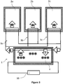
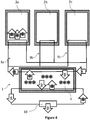
- FIG. 3 to FIG. 6 After different aspects of the components of a centralized cooling device for compartments of an analysis system have been discussed in the preceding sections, several details of modes of operation of the centralized cooling system will be discussed subsequently in connection with FIG. 3 to FIG. 6 .
- the example analysis system of FIG. 3 to FIG. 6 are drawn in a schematic manner. However, each of the systems depicted in FIG. 3 to FIG. 6 can include one or more of the components described above in connection with FIG. 2 .
- the compartment cooling circuits 3a, 3b, 3c can operate independently from the main cooling circuit 1.
- the main cooling circuit 1 can be intermittently switched off.
- the compartment cooling circuits 3a, 3b, 3c can nevertheless deposit heat from the compartments into the cold storage 4.
- the compartment cooling circuits 3a, 3b, 3c utilize the cooling energy buffered in the cold storage 4.
- the main cooling circuit can deposit cooling energy 4 into the cold storage independently of the operation of the compartment cooling circuits 3a, 3b, 3c.
- one or more of the compartment cooling circuits 3a, 3b, 3c can be disabled so that no or a reduced amount of heat is deposited in the cold storage 4 by the compartment cooling circuits 3a, 3b, 3c in certain periods of time. This can be the case, e.g., when the cooling system of the analysis system is being started or when additional compartment cooling circuits are being coupled to the cold storage 4.
- the main cooling circuit can include a controller which monitors an amount of cooling energy stored in the cold storage 4 and cools the cold storage 4 as soon as the amount of cooling energy falls within a predetermined level.
- the amount of cooling energy can be determined by the controller in response to a temperature measurement of the cold storage agent inside the cold storage 4.
- the cold storage 4 can include one or more temperature sensors to measure a temperature of the cold storage agent inside the cold storage 4.
- the controller can determine an amount of cold storage agent in a particular aggregate state to monitor an amount of cooling energy stored in the cold storage 4. Moreover, the controller can drive the main cooling circuit to deposit additional cooling energy into the cold storage 4 in response to determining an amount of cold storage agent being in a particular aggregate state (e.g., in response to determining that an amount of cold storage agent in a solid state falls below a predetermined level or one of a plurality of predetermined levels).
- the controller can monitor an amount of ice present in the one or more ice banks and control the main cooling circuit in response to the amount of ice present. For instance, the controller can drive the main cooling circuit 1 to deposit cooling energy into the cold storage 4 when an amount of ice drops below a predetermined level (e.g., when no ice is left in the ice bank or when one of one or more reserve levels) of ice is reached.
- a predetermined level e.g., when no ice is left in the ice bank or when one of one or more reserve levels
- the controller might not have to monitor the amount of heat deposited into the cold storage 4 by the compartment cooling circuits 3a, 3b, 3c.
- the controller can be configured to secure that a certain amount of cooling energy is stored in the cold storage 4 (e.g., a minimum amount of ice in examples where the cold storage 4 includes an ice bank). This can ensure that the compartment cooling circuits 3a, 3b, 3c can deposit the required amount of heat into the cold storage 4 to cool the compartments 2a, 2b, 2c.
- the controller can monitor an amount of heat deposited into the cold storage 4 by the compartment cooling circuits 3a, 3b, 3c. In addition or alternatively, the controller can estimate an amount of heat deposited into the cold storage 4 by the compartment cooling circuits 3a, 3b, 3c (in some examples without actually monitoring the compartment cooling circuits 3a, 3b, 3c.). The controller can then drive the main cooling circuit 1 to buffer a predetermined amount of cooling energy into the cold storage 4 based on the amount of heat deposited in the cold storage 4 by the compartment cooling circuits 3a, 3b, 3c. This can take place instead or in addition to controlling the main cooling circuit 1 in response to monitoring an amount of cooling energy stored in the cold storage 4 as described above.
- the controller can monitor a temperature of the coolant, a flow volume of the coolant, or both in one or more flow or return lines (or in both the flow and return lines) of the compartment cooling circuits 3a, 3b, 3c to estimate an amount of energy deposited into the cold storage 4 by the respective compartment cooling circuits 3a, 3b, 3c.
- the compartment cooling circuits 3a, 3b, 3c can be equipped with one or more temperature sensors to measure the temperature of the coolant in the flow and return lines.
- a flow volume of the coolant in the flow and return lines of the compartment cooling circuits can be measured or estimated (e.g., based on the operation parameters of the flow control units).
- the controller can receive information regarding the temperature of the compartments to estimate an amount of energy deposited into the cold storage 4 (e.g., a future requirement of cooling energy of the respective compartment 2a, 2b, 2c).
- the controller can receive other information regarding a state of a compartment 2a, 2b, 2c (e.g., a door opening sensor of the compartment or a load state sensor of the compartment) to estimate an amount of energy deposited into the cold storage 4.
- the controller can be configured to calculate an amount of cooling energy to be buffered based on statistical energy consumption information from the analysis system. For instance, the controller can calculate an amount of cooling energy to be buffered based on an average energy consumption of the attached compartments 2a, 2b, 2c over a predetermined period of time.
- the controller can use information regarding a nominal energy consumption of the attached compartments 2a, 2b, 2c to calculate an amount of cooling energy to be buffered. For example, the controller can estimate an energy consumption for a particular type of compartment.
- the controller can calculate a past and or future amount of deposited energy into the cold storage 4 based on one or more of the above discussed pieces of information and drive the main cooling circuit 1 in response to this calculation. In this manner, a sufficient amount of cooling energy can be buffered in the cold storage 4 to satisfy the cooling needs of the attached compartments 2a, 2b, 2c.
- the controller can use one or more closed-loop or open-loop control schemes to determine a drive sequence of the main cooling circuit 1.
- Controlling an amount of cooling energy stored into the cold storage based on the energy consumption of the compartment cooling circuits can provide for a simple and robust control parameter to control the main cooling system.
- the cooling device can be easily scalable to adapt for a variety of different numbers and sizes of compartments to be cooled in the analysis system.
- the different compartments 2a, 2b, 2c can be individually cooled.
- a first compartment 2a can be cooled to a first temperature while a second compartment 2b can be cooled to a second temperature.
- a compartment cooling circuit of a particular compartment can be switched off while another compartment of the analysis system is cooled to a predetermined temperature.
- one compartment 2a can be continuously cooled while another compartment 2c can be cooled intermittently (e.g., when a particular trigger event takes place).
- the controller of the analysis system can effect the individual cooling of the compartments 2a, 2b, 2b by controlling temperature regulating units of the respective compartment cooling circuits 3a, 3b, 3c (e.g., flow regulators as discussed above in connection with FIG. 2 ), as discussed above in connection with FIG. 2 ).
- temperature regulating units of the respective compartment cooling circuits 3a, 3b, 3c e.g., flow regulators as discussed above in connection with FIG. 2 ), as discussed above in connection with FIG. 2 ).
- the controller can change a flow of coolant through a particular compartment cooling circuit 3a, 3b, 3c to change an amount of heat extracted from the respective compartment 2a, 2b, 2c.
- the controller can control a pump of a flow rate regulator of a compartment cooling circuit, a controlled valve of a flow rate regulator of a compartment cooling circuit, or both, to change a flow of coolant through the particular compartment cooling circuit 3a, 3b, 3c and thereby change an amount of heat extracted from the respective compartment 2a, 2b, 2c.
- the controller can change drive parameters of a fan of a temperature regulation unit (or a parameter of another controllable component of the temperature regulation unit) of a respective compartment 2a, 2b, 2c to change an amount of heat extracted from the respective compartment 2a, 2b, 2c.
- the controller receives information from one or more temperature sensors of the compartment 2a, 2b, 2c to estimate a temperature inside the particular compartments 2a, 2b, 2c and a required amount of heat that has to be extracted from the respective compartment 2a, 2b, 2c.
- FIG. 6 illustrates a further mode of operation of the controller of the compartment cooling circuits 3a, 3b, 3c.
- the controller is configured to set priorities for the use of the buffered cooling energy by the different compartment cooling circuits 3a, 3b, 3c in case an insufficient amount of cooling energy is buffered.
- the controller can reduce the amount of heat extracted from one or more compartments having a lower priority (e.g., by reducing or stopping a flow of coolant through the respective compartment cooling circuits) to secure that a higher priority compartment is adequately provided with cooling energy.
- the compartment 2a is a prioritized compartment.
- the compartment 2a can contain biological samples or reagents very sensitive to storage temperatures while the compartments 2b, 2c can contain less sensitive reagents.
- the controller controls the compartment cooling circuits 3a, 3b, 3c to exclusively provide compartment 2a with cooling energy.
- the cooling system of the present disclosure can provide for a fail safe state if, e.g., the main cooling circuit or the cold storage are temporarily or permanently unable to provide a sufficient cooling power to cool all compartments of the analysis system to their nominal temperatures.
- the analysis system can be optionally equipped with one or more devices to use waste heat generated in the main cooling circuit, the compartment cooling circuits, and/or the cold storage in the analysis system.
- the analysis system can include a device configured to harvest a portion of heat generated in a condenser of the refrigeration device to generate energy or to heat one or more components of the analysis system.
- the analysis system further comprises one or more heaters and a heat transport circuit configured to transport the portion of the heat generated in the condenser to the one or more heaters.
- the analysis system can transform waste heat generated in the main cooling circuit, the compartment cooling circuits, and/or the cold storage into electrical energy which can be used in the analysis system.
- the analysis system can harvest at least a portion of latent heat liberated when a cold storage agent of the cold storage changes an aggregation state.
- the described systems and methods can also be used to heat one or more compartments of an analysis system.
- an analysis system for analyzing biological samples can comprise a plurality of compartments, a plurality of compartment heating circuits, each of the plurality of compartment heating circuits is configured to heat at least one of the plurality of compartments, a main heating circuit separate from the one or more compartment heating circuits, the main heating circuit including a heat storage, the main heating circuit being coupled to the heat storage and configured to heat the heat storage, the one or more compartment heating circuits are coupled to the heat storage and the one or more compartment heating circuits being configured to transfer heat into the plurality of compartments from the heat storage to heat the plurality of compartments.
- the heating system is fairly similar to the cooling system discussed above apart from that the direction of heat transfer is reversed.
- the different components of the cooling system described above and the different techniques to control a cooling system described above can equally be applied in a heating system (except for the components and techniques being specific to a cooling system).
Landscapes
- Engineering & Computer Science (AREA)
- Chemical & Material Sciences (AREA)
- Combustion & Propulsion (AREA)
- Physics & Mathematics (AREA)
- Mechanical Engineering (AREA)
- Thermal Sciences (AREA)
- General Engineering & Computer Science (AREA)
- Automatic Analysis And Handling Materials Therefor (AREA)
Claims (15)
- Analysesystem zum Analysieren biologischer Proben, umfassend eine Steuerung, die funktional an ein oder mehrere analytische, vor- oder nachanalytische Arbeitszellen gekoppelt ist, wobei die Steuerung funktional ist, um die Arbeitszellen zu steuern, wobei das Analysesystem umfasst:eine Vielzahl von Abteilungen (2a; 2b; 2c);eine Vielzahl von Abteilungskühlkreisen (3a; 3b; 3c),wobei jeder von der Vielzahl der Abteilungskühlkreise (3a; 3b; 3c) ausgestaltet ist, um mindestens eine von der Vielzahl der Abteilungen (2a; 2b; 2c) zu kühlen;einen Hauptkühlkreis (1), der getrennt von dem einen oder den mehreren Abteilungskühlkreisen (3a; 3b; 3c) vorliegt, wobei der Hauptkühlkreis (1) eine Kälteerzeugungsvorrichtung (10-13) einschließt; undeinen Kältespeicher (4), wobei der Hauptkühlkreis (1) an den Kältespeicher (4) gekoppelt ist und ausgestaltet ist, um den Kältespeicher (4) zu kühlen,wobei der eine oder die mehreren Abteilungskühlkreise (3a; 3b; 3c) an den Kältespeicher (4) gekoppelt sind, undwobei der eine oder die mehreren Abteilungskühlkreise (3a; 3b; 3c) ausgestaltet sind, um Wärme von der Vielzahl der Abteilungen (2a; 2b; 2c) in den Kältespeicher (4) zu übertragen, um die Vielzahl der Abteilungen (2a; 2b; 2c) zu kühlen, undwobei der Kältespeicher (4) vorgesehen ist, um Kühlenergie zu puffern,dadurch gekennzeichnet, dass:
die Steuerung ausgestaltet ist, um eine Energiemenge zu überwachen, die in dem Kältespeicher (4) gepuffert wird, und um den Hauptkühlkreis (1) in Reaktion auf die gemessene Energiemenge in dem Kältespeicher (4) zu steuern. - Analysesystem nach Anspruch 1, wobei die Abteilungen (2a; 2b; 2c) ein oder mehrere von einer Probenlagerungsabteilung, einer Reagenzlagerungsabteilung, einer Reagenzmanipulatorabteilung, einer Probenmanipulatorabteilung und einer Qualitätskontrollabteilung einschließen.
- Analysesystem nach Anspruch 1 oder 2, wobei die Kälteerzeugungsvorrichtung (10-13) eine zyklische Kälteerzeugungsvorrichtung ist, wobei die zyklische Kälteerzeugungsvorrichtung (10-13) vorzugsweise eine Dampfkompressionskälteerzeugungsvorrichtung oder eine Dampfabsorptionskälteerzeugungsvorrichtung ist.
- Analysesystem nach Anspruch 3, wobei die zyklische Kälteerzeugungsvorrichtung (10-13) mindestens einen Kompressor (11), mindestens eine Expansionsvorrichtung (12) und mindestens einen Kondensator (10) einschließt, wobei ein Anteil der in dem Kondensator (10) erzeugten Wärme in dem Analysesystem zum Erzeugen von Energie oder zum Erwärmen von einer oder mehreren Komponenten des Analysesystems verwendet wird.
- Analysesystem nach einem der vorhergehenden Ansprüche, wobei ein oder mehrere beliebige der Abteilungskühlkreise (3a; 3b; 3c) eine Temperaturregelungseinheit (6a; 6b; 6c; 7a; 7b; 7c) zum Anpassen der Temperatur der jeweiligen Abteilung (2a; 2b; 2c) einschließt bzw. einschließen.
- Analysesystem nach Anspruch 5, wobei die Temperaturregelungseinheit einen Durchflussratenregler (6a; 6b; 6c) einschließt.
- Analysesystem nach Anspruch 6, wobei der Durchflussratenregler (6a; 6b; 6c) ein gesteuertes Ventil einschließt.
- Analysesystem nach einem der vorhergehenden Ansprüche, wobei der Kältespeicher eine oder mehrere Eisbänke (4) einschließt.
- Analysesystem nach einem der vorhergehenden Ansprüche, wobei der Hauptkühlkreis (1) ausgestaltet ist, um intermittierend betrieben zu werden, um den Kältespeicher (4) zu kühlen.
- Analysesystem nach Anspruch 1, wobei die Steuerung ausgestaltet ist, um eine zu puffernde Menge an Kühlenergie basierend auf statistischen Energieverbrauchsinformationen aus dem Analysesystem zu berechnen.
- Analysesystem nach einem der Ansprüche 1 oder 10, wobei die Steuerung ausgestaltet ist, um die Temperaturregelungseinheit(en) (6a; 6b; 6c; 7a; 7b; 7c) zu steuern, um die Temperaturen von individuellen Abteilungen (2a; 2b; 2c) gemäß den Anforderungen der jeweiligen Abteilung (2a; 2b; 2c) individuell anzupassen.
- Analysesystem nach einem der Ansprüche 1 und 10 bis 11, wobei die Steuerung ausgestaltet ist, um Prioritäten für die Verwendung der gepufferten Kühlenergie durch die unterschiedlichen Abteilungskühlkreise (3a; 3b; 3c) festzulegen, falls eine unzureichende Menge an Kühlenergie gepuffert wird.
- Analysesystem nach einem der vorhergehenden Ansprüche, wobei das Analysesystem ein Analysegerät der klinischen Chemie, ein Analysegerät für Koagulationschemie, ein Analysegerät für Immunochemie, ein Urinanalysegerät oder ein Nukleinsäureanalysegerät ist.
- Analysesystem nach einem der vorhergehenden Ansprüche, wobei der Kältespeicher (4) ein Kältespeichermittel einschließt, das ausgestaltet ist, um seinen Aggregatzustand zu ändern, wenn der Hauptkühlkreis (1) den Kältespeicher (4) kühlt.
- Verfahren zum Kühlen einer Vielzahl von Abteilungen (2a; 2b; 2c) eines Analysesystems, das biologische Proben analysiert, umfassend eine Steuerung, die funktional an ein oder mehrere analytische, vor- oder nachanalytische Arbeitszellen gekoppelt ist, wobei die Steuerung funktional ist, um die Arbeitszellen zu steuern, wobei das Verfahren umfasst:Kühlen eines Kältespeichers (4) durch einen Hauptkühlkreis (1), der eine Kälteerzeugungsvorrichtung (10-13) einschließt;Ablegen von Wärme in dem Kältespeicher (4) durch eine Vielzahl von Abteilungskühlkreisen (3a; 3b; 3c), um die Vielzahl der Abteilungen (2a; 2b; 2c) des Analysesystems zu kühlen, wobei die Vielzahl der Abteilungskühlkreise (3a; 3b; 3c) getrennt von dem Hauptkühlkreis (1) vorliegt,wobei der Kältespeicher (4) vorgesehen ist, um Kühlenergie zu puffern,dadurch gekennzeichnet, dass die Steuerung des Analysesystems ausgestaltet ist, um eine Energiemenge zu überwachen, die in dem Kältespeicher (4) gepuffert wird, und um den Hauptkühlkreis (1) in Reaktion auf die gemessene Energiemenge in dem Kältespeicher (4) zu steuern.
Priority Applications (1)
| Application Number | Priority Date | Filing Date | Title |
|---|---|---|---|
| EP15186701.7A EP3147602B1 (de) | 2015-09-24 | 2015-09-24 | Zentralisierter kühlkreislauf |
Applications Claiming Priority (1)
| Application Number | Priority Date | Filing Date | Title |
|---|---|---|---|
| EP15186701.7A EP3147602B1 (de) | 2015-09-24 | 2015-09-24 | Zentralisierter kühlkreislauf |
Publications (2)
| Publication Number | Publication Date |
|---|---|
| EP3147602A1 EP3147602A1 (de) | 2017-03-29 |
| EP3147602B1 true EP3147602B1 (de) | 2020-04-08 |
Family
ID=54251314
Family Applications (1)
| Application Number | Title | Priority Date | Filing Date |
|---|---|---|---|
| EP15186701.7A Active EP3147602B1 (de) | 2015-09-24 | 2015-09-24 | Zentralisierter kühlkreislauf |
Country Status (1)
| Country | Link |
|---|---|
| EP (1) | EP3147602B1 (de) |
Family Cites Families (8)
| Publication number | Priority date | Publication date | Assignee | Title |
|---|---|---|---|---|
| US2512545A (en) * | 1948-06-11 | 1950-06-20 | Frederick E Hazard | Structure for and method of transfer, exchange, control regulation, and storage of heat and cold |
| US4173993A (en) * | 1972-10-04 | 1979-11-13 | Skala Stephen F | Domestic appliance system with thermal exchange fluid |
| NL7908309A (nl) * | 1979-11-13 | 1981-06-01 | Spijkstaal Hoogeveen B V | Koelinstallatie. |
| JPS61175467A (ja) * | 1985-01-29 | 1986-08-07 | ホシザキ電機株式会社 | 冷蔵庫の温度制御方法およびその装置 |
| DE19735584C2 (de) * | 1997-08-16 | 1999-12-09 | Integral Energietechnik Gmbh | Doppelwandige Kühlzelle |
| US5921092A (en) * | 1998-03-16 | 1999-07-13 | Hussmann Corporation | Fluid defrost system and method for secondary refrigeration systems |
| DE102010043245A1 (de) * | 2010-11-03 | 2012-05-03 | BSH Bosch und Siemens Hausgeräte GmbH | Kältegerät mit Pufferspeicher |
| DE102012207687A1 (de) * | 2012-05-09 | 2013-11-14 | BSH Bosch und Siemens Hausgeräte GmbH | Haushaltskältegerät mit einem mit dem Gefrierfach gekoppelten Kältespeicher |
-
2015
- 2015-09-24 EP EP15186701.7A patent/EP3147602B1/de active Active
Non-Patent Citations (1)
| Title |
|---|
| None * |
Also Published As
| Publication number | Publication date |
|---|---|
| EP3147602A1 (de) | 2017-03-29 |
Similar Documents
| Publication | Publication Date | Title |
|---|---|---|
| EP2677251B1 (de) | Kältekreislaufvorrichtung und kältekreislaufsteuerverfahren | |
| KR100872225B1 (ko) | 냉장고의 제어방법 | |
| EP3985397B1 (de) | Automatische analysevorrichtung | |
| EP3136009A1 (de) | Klimaanlage und abtaubetriebsverfahren dafür | |
| CN102192626B (zh) | 使用液态冷冻剂的冷冻器及方法 | |
| US20200214173A1 (en) | Phase-change cooling apparatus and phase-change cooling method | |
| EP3462159B1 (de) | Kondenswassersammler | |
| EP3658829A1 (de) | System zur messung einer kältemittelzusammensetzung | |
| CN108019998A (zh) | 改善接水盘化霜水蒸发能力的控制方法、控制器及冰箱 | |
| CN109221083A (zh) | 一种自动控制降温速率的降温设备 | |
| DK177395B1 (en) | A method for operating a refrigeration system for a cargo container | |
| Wang et al. | Vapor quality and performance of an automotive air conditioning system | |
| US20140352335A1 (en) | Adaptive defrost | |
| CN108061420B (zh) | 温度调控方法、温度调控装置、制冷设备和可读存储介质 | |
| EP3147602A1 (de) | Zentralisierter kühlkreislauf | |
| CN115362340A (zh) | 用于hvac系统的自由冷却系统 | |
| EP2000754B1 (de) | Verfahren zur Schätzung der Wärmebelastung einer Leitung für eine Betriebsflüssigkeit am Auslass einer Kühlmaschine | |
| CN113654289A (zh) | 一种试剂冷藏装置及制冷方法 | |
| CN1172273C (zh) | 自动售货机的冷却装置 | |
| WO2014142130A1 (ja) | 保冷庫、保冷庫の制御方法及び保冷庫の制御プログラム | |
| JP7369057B2 (ja) | 自動分析装置 | |
| JP4265368B2 (ja) | ショーケース、ショーケースの強制デフロスト運転制御装置、強制デフロスト運転制御システムおよび強制デフロスト運転制御プログラム | |
| JP2018096681A (ja) | 冷媒充填量判定システム | |
| CN115437426B (zh) | 一种恒温箱控制系统及其控制方法 | |
| CN116296496B (zh) | 一种空气能实验室混合水箱系统、控制方法及存储介质 |
Legal Events
| Date | Code | Title | Description |
|---|---|---|---|
| PUAI | Public reference made under article 153(3) epc to a published international application that has entered the european phase |
Free format text: ORIGINAL CODE: 0009012 |
|
| STAA | Information on the status of an ep patent application or granted ep patent |
Free format text: STATUS: THE APPLICATION HAS BEEN PUBLISHED |
|
| AK | Designated contracting states |
Kind code of ref document: A1 Designated state(s): AL AT BE BG CH CY CZ DE DK EE ES FI FR GB GR HR HU IE IS IT LI LT LU LV MC MK MT NL NO PL PT RO RS SE SI SK SM TR |
|
| AX | Request for extension of the european patent |
Extension state: BA ME |
|
| STAA | Information on the status of an ep patent application or granted ep patent |
Free format text: STATUS: REQUEST FOR EXAMINATION WAS MADE |
|
| 17P | Request for examination filed |
Effective date: 20170907 |
|
| RBV | Designated contracting states (corrected) |
Designated state(s): AL AT BE BG CH CY CZ DE DK EE ES FI FR GB GR HR HU IE IS IT LI LT LU LV MC MK MT NL NO PL PT RO RS SE SI SK SM TR |
|
| STAA | Information on the status of an ep patent application or granted ep patent |
Free format text: STATUS: EXAMINATION IS IN PROGRESS |
|
| 17Q | First examination report despatched |
Effective date: 20180518 |
|
| GRAP | Despatch of communication of intention to grant a patent |
Free format text: ORIGINAL CODE: EPIDOSNIGR1 |
|
| STAA | Information on the status of an ep patent application or granted ep patent |
Free format text: STATUS: GRANT OF PATENT IS INTENDED |
|
| INTG | Intention to grant announced |
Effective date: 20191011 |
|
| GRAS | Grant fee paid |
Free format text: ORIGINAL CODE: EPIDOSNIGR3 |
|
| GRAJ | Information related to disapproval of communication of intention to grant by the applicant or resumption of examination proceedings by the epo deleted |
Free format text: ORIGINAL CODE: EPIDOSDIGR1 |
|
| GRAL | Information related to payment of fee for publishing/printing deleted |
Free format text: ORIGINAL CODE: EPIDOSDIGR3 |
|
| STAA | Information on the status of an ep patent application or granted ep patent |
Free format text: STATUS: EXAMINATION IS IN PROGRESS |
|
| GRAR | Information related to intention to grant a patent recorded |
Free format text: ORIGINAL CODE: EPIDOSNIGR71 |
|
| STAA | Information on the status of an ep patent application or granted ep patent |
Free format text: STATUS: GRANT OF PATENT IS INTENDED |
|
| GRAA | (expected) grant |
Free format text: ORIGINAL CODE: 0009210 |
|
| STAA | Information on the status of an ep patent application or granted ep patent |
Free format text: STATUS: THE PATENT HAS BEEN GRANTED |
|
| INTC | Intention to grant announced (deleted) | ||
| INTG | Intention to grant announced |
Effective date: 20200225 |
|
| AK | Designated contracting states |
Kind code of ref document: B1 Designated state(s): AL AT BE BG CH CY CZ DE DK EE ES FI FR GB GR HR HU IE IS IT LI LT LU LV MC MK MT NL NO PL PT RO RS SE SI SK SM TR |
|
| REG | Reference to a national code |
Ref country code: CH Ref legal event code: EP Ref country code: AT Ref legal event code: REF Ref document number: 1254939 Country of ref document: AT Kind code of ref document: T Effective date: 20200415 |
|
| REG | Reference to a national code |
Ref country code: DE Ref legal event code: R096 Ref document number: 602015050177 Country of ref document: DE |
|
| REG | Reference to a national code |
Ref country code: IE Ref legal event code: FG4D |
|
| REG | Reference to a national code |
Ref country code: NL Ref legal event code: MP Effective date: 20200408 |
|
| REG | Reference to a national code |
Ref country code: LT Ref legal event code: MG4D |
|
| PG25 | Lapsed in a contracting state [announced via postgrant information from national office to epo] |
Ref country code: SE Free format text: LAPSE BECAUSE OF FAILURE TO SUBMIT A TRANSLATION OF THE DESCRIPTION OR TO PAY THE FEE WITHIN THE PRESCRIBED TIME-LIMIT Effective date: 20200408 Ref country code: GR Free format text: LAPSE BECAUSE OF FAILURE TO SUBMIT A TRANSLATION OF THE DESCRIPTION OR TO PAY THE FEE WITHIN THE PRESCRIBED TIME-LIMIT Effective date: 20200709 Ref country code: FI Free format text: LAPSE BECAUSE OF FAILURE TO SUBMIT A TRANSLATION OF THE DESCRIPTION OR TO PAY THE FEE WITHIN THE PRESCRIBED TIME-LIMIT Effective date: 20200408 Ref country code: NO Free format text: LAPSE BECAUSE OF FAILURE TO SUBMIT A TRANSLATION OF THE DESCRIPTION OR TO PAY THE FEE WITHIN THE PRESCRIBED TIME-LIMIT Effective date: 20200708 Ref country code: IS Free format text: LAPSE BECAUSE OF FAILURE TO SUBMIT A TRANSLATION OF THE DESCRIPTION OR TO PAY THE FEE WITHIN THE PRESCRIBED TIME-LIMIT Effective date: 20200808 Ref country code: PT Free format text: LAPSE BECAUSE OF FAILURE TO SUBMIT A TRANSLATION OF THE DESCRIPTION OR TO PAY THE FEE WITHIN THE PRESCRIBED TIME-LIMIT Effective date: 20200817 Ref country code: NL Free format text: LAPSE BECAUSE OF FAILURE TO SUBMIT A TRANSLATION OF THE DESCRIPTION OR TO PAY THE FEE WITHIN THE PRESCRIBED TIME-LIMIT Effective date: 20200408 Ref country code: LT Free format text: LAPSE BECAUSE OF FAILURE TO SUBMIT A TRANSLATION OF THE DESCRIPTION OR TO PAY THE FEE WITHIN THE PRESCRIBED TIME-LIMIT Effective date: 20200408 |
|
| REG | Reference to a national code |
Ref country code: AT Ref legal event code: MK05 Ref document number: 1254939 Country of ref document: AT Kind code of ref document: T Effective date: 20200408 |
|
| PG25 | Lapsed in a contracting state [announced via postgrant information from national office to epo] |
Ref country code: LV Free format text: LAPSE BECAUSE OF FAILURE TO SUBMIT A TRANSLATION OF THE DESCRIPTION OR TO PAY THE FEE WITHIN THE PRESCRIBED TIME-LIMIT Effective date: 20200408 Ref country code: HR Free format text: LAPSE BECAUSE OF FAILURE TO SUBMIT A TRANSLATION OF THE DESCRIPTION OR TO PAY THE FEE WITHIN THE PRESCRIBED TIME-LIMIT Effective date: 20200408 Ref country code: BG Free format text: LAPSE BECAUSE OF FAILURE TO SUBMIT A TRANSLATION OF THE DESCRIPTION OR TO PAY THE FEE WITHIN THE PRESCRIBED TIME-LIMIT Effective date: 20200708 Ref country code: RS Free format text: LAPSE BECAUSE OF FAILURE TO SUBMIT A TRANSLATION OF THE DESCRIPTION OR TO PAY THE FEE WITHIN THE PRESCRIBED TIME-LIMIT Effective date: 20200408 |
|
| PG25 | Lapsed in a contracting state [announced via postgrant information from national office to epo] |
Ref country code: AL Free format text: LAPSE BECAUSE OF FAILURE TO SUBMIT A TRANSLATION OF THE DESCRIPTION OR TO PAY THE FEE WITHIN THE PRESCRIBED TIME-LIMIT Effective date: 20200408 |
|
| REG | Reference to a national code |
Ref country code: DE Ref legal event code: R097 Ref document number: 602015050177 Country of ref document: DE |
|
| PG25 | Lapsed in a contracting state [announced via postgrant information from national office to epo] |
Ref country code: CZ Free format text: LAPSE BECAUSE OF FAILURE TO SUBMIT A TRANSLATION OF THE DESCRIPTION OR TO PAY THE FEE WITHIN THE PRESCRIBED TIME-LIMIT Effective date: 20200408 Ref country code: RO Free format text: LAPSE BECAUSE OF FAILURE TO SUBMIT A TRANSLATION OF THE DESCRIPTION OR TO PAY THE FEE WITHIN THE PRESCRIBED TIME-LIMIT Effective date: 20200408 Ref country code: IT Free format text: LAPSE BECAUSE OF FAILURE TO SUBMIT A TRANSLATION OF THE DESCRIPTION OR TO PAY THE FEE WITHIN THE PRESCRIBED TIME-LIMIT Effective date: 20200408 Ref country code: SM Free format text: LAPSE BECAUSE OF FAILURE TO SUBMIT A TRANSLATION OF THE DESCRIPTION OR TO PAY THE FEE WITHIN THE PRESCRIBED TIME-LIMIT Effective date: 20200408 Ref country code: DK Free format text: LAPSE BECAUSE OF FAILURE TO SUBMIT A TRANSLATION OF THE DESCRIPTION OR TO PAY THE FEE WITHIN THE PRESCRIBED TIME-LIMIT Effective date: 20200408 Ref country code: EE Free format text: LAPSE BECAUSE OF FAILURE TO SUBMIT A TRANSLATION OF THE DESCRIPTION OR TO PAY THE FEE WITHIN THE PRESCRIBED TIME-LIMIT Effective date: 20200408 Ref country code: AT Free format text: LAPSE BECAUSE OF FAILURE TO SUBMIT A TRANSLATION OF THE DESCRIPTION OR TO PAY THE FEE WITHIN THE PRESCRIBED TIME-LIMIT Effective date: 20200408 Ref country code: ES Free format text: LAPSE BECAUSE OF FAILURE TO SUBMIT A TRANSLATION OF THE DESCRIPTION OR TO PAY THE FEE WITHIN THE PRESCRIBED TIME-LIMIT Effective date: 20200408 |
|
| PLBE | No opposition filed within time limit |
Free format text: ORIGINAL CODE: 0009261 |
|
| STAA | Information on the status of an ep patent application or granted ep patent |
Free format text: STATUS: NO OPPOSITION FILED WITHIN TIME LIMIT |
|
| PG25 | Lapsed in a contracting state [announced via postgrant information from national office to epo] |
Ref country code: SK Free format text: LAPSE BECAUSE OF FAILURE TO SUBMIT A TRANSLATION OF THE DESCRIPTION OR TO PAY THE FEE WITHIN THE PRESCRIBED TIME-LIMIT Effective date: 20200408 Ref country code: PL Free format text: LAPSE BECAUSE OF FAILURE TO SUBMIT A TRANSLATION OF THE DESCRIPTION OR TO PAY THE FEE WITHIN THE PRESCRIBED TIME-LIMIT Effective date: 20200408 |
|
| 26N | No opposition filed |
Effective date: 20210112 |
|
| PG25 | Lapsed in a contracting state [announced via postgrant information from national office to epo] |
Ref country code: MC Free format text: LAPSE BECAUSE OF FAILURE TO SUBMIT A TRANSLATION OF THE DESCRIPTION OR TO PAY THE FEE WITHIN THE PRESCRIBED TIME-LIMIT Effective date: 20200408 |
|
| REG | Reference to a national code |
Ref country code: CH Ref legal event code: PL |
|
| GBPC | Gb: european patent ceased through non-payment of renewal fee |
Effective date: 20200924 |
|
| PG25 | Lapsed in a contracting state [announced via postgrant information from national office to epo] |
Ref country code: SI Free format text: LAPSE BECAUSE OF FAILURE TO SUBMIT A TRANSLATION OF THE DESCRIPTION OR TO PAY THE FEE WITHIN THE PRESCRIBED TIME-LIMIT Effective date: 20200408 |
|
| REG | Reference to a national code |
Ref country code: BE Ref legal event code: MM Effective date: 20200930 |
|
| PG25 | Lapsed in a contracting state [announced via postgrant information from national office to epo] |
Ref country code: LU Free format text: LAPSE BECAUSE OF NON-PAYMENT OF DUE FEES Effective date: 20200924 |
|
| PG25 | Lapsed in a contracting state [announced via postgrant information from national office to epo] |
Ref country code: CH Free format text: LAPSE BECAUSE OF NON-PAYMENT OF DUE FEES Effective date: 20200930 Ref country code: BE Free format text: LAPSE BECAUSE OF NON-PAYMENT OF DUE FEES Effective date: 20200930 Ref country code: GB Free format text: LAPSE BECAUSE OF NON-PAYMENT OF DUE FEES Effective date: 20200924 Ref country code: IE Free format text: LAPSE BECAUSE OF NON-PAYMENT OF DUE FEES Effective date: 20200924 Ref country code: LI Free format text: LAPSE BECAUSE OF NON-PAYMENT OF DUE FEES Effective date: 20200930 |
|
| PG25 | Lapsed in a contracting state [announced via postgrant information from national office to epo] |
Ref country code: TR Free format text: LAPSE BECAUSE OF FAILURE TO SUBMIT A TRANSLATION OF THE DESCRIPTION OR TO PAY THE FEE WITHIN THE PRESCRIBED TIME-LIMIT Effective date: 20200408 Ref country code: MT Free format text: LAPSE BECAUSE OF FAILURE TO SUBMIT A TRANSLATION OF THE DESCRIPTION OR TO PAY THE FEE WITHIN THE PRESCRIBED TIME-LIMIT Effective date: 20200408 Ref country code: CY Free format text: LAPSE BECAUSE OF FAILURE TO SUBMIT A TRANSLATION OF THE DESCRIPTION OR TO PAY THE FEE WITHIN THE PRESCRIBED TIME-LIMIT Effective date: 20200408 |
|
| PG25 | Lapsed in a contracting state [announced via postgrant information from national office to epo] |
Ref country code: MK Free format text: LAPSE BECAUSE OF FAILURE TO SUBMIT A TRANSLATION OF THE DESCRIPTION OR TO PAY THE FEE WITHIN THE PRESCRIBED TIME-LIMIT Effective date: 20200408 |
|
| PGFP | Annual fee paid to national office [announced via postgrant information from national office to epo] |
Ref country code: DE Payment date: 20250820 Year of fee payment: 11 |
|
| PGFP | Annual fee paid to national office [announced via postgrant information from national office to epo] |
Ref country code: FR Payment date: 20250820 Year of fee payment: 11 |