EP3147600B1 - Refrigeration apparatus - Google Patents
Refrigeration apparatus Download PDFInfo
- Publication number
- EP3147600B1 EP3147600B1 EP16190676.3A EP16190676A EP3147600B1 EP 3147600 B1 EP3147600 B1 EP 3147600B1 EP 16190676 A EP16190676 A EP 16190676A EP 3147600 B1 EP3147600 B1 EP 3147600B1
- Authority
- EP
- European Patent Office
- Prior art keywords
- compartment
- refrigerant
- temperature
- refrigeration apparatus
- fluid control
- Prior art date
- Legal status (The legal status is an assumption and is not a legal conclusion. Google has not performed a legal analysis and makes no representation as to the accuracy of the status listed.)
- Active
Links
- 238000005057 refrigeration Methods 0.000 title claims description 73
- 239000003507 refrigerant Substances 0.000 claims description 148
- 239000012530 fluid Substances 0.000 claims description 50
- 230000008878 coupling Effects 0.000 claims description 31
- 238000010168 coupling process Methods 0.000 claims description 31
- 238000005859 coupling reaction Methods 0.000 claims description 31
- 238000000034 method Methods 0.000 claims description 25
- 238000001816 cooling Methods 0.000 claims description 16
- IJGRMHOSHXDMSA-UHFFFAOYSA-N Atomic nitrogen Chemical compound N#N IJGRMHOSHXDMSA-UHFFFAOYSA-N 0.000 description 26
- 239000007788 liquid Substances 0.000 description 17
- 229910052757 nitrogen Inorganic materials 0.000 description 13
- CURLTUGMZLYLDI-UHFFFAOYSA-N Carbon dioxide Chemical compound O=C=O CURLTUGMZLYLDI-UHFFFAOYSA-N 0.000 description 7
- 238000007710 freezing Methods 0.000 description 5
- 230000008014 freezing Effects 0.000 description 5
- XKRFYHLGVUSROY-UHFFFAOYSA-N Argon Chemical compound [Ar] XKRFYHLGVUSROY-UHFFFAOYSA-N 0.000 description 4
- 239000001569 carbon dioxide Substances 0.000 description 3
- 229910002092 carbon dioxide Inorganic materials 0.000 description 3
- 239000007789 gas Substances 0.000 description 3
- 229910052786 argon Inorganic materials 0.000 description 2
- 235000013611 frozen food Nutrition 0.000 description 2
- 238000003915 air pollution Methods 0.000 description 1
- 235000011089 carbon dioxide Nutrition 0.000 description 1
- 238000002485 combustion reaction Methods 0.000 description 1
- 230000003247 decreasing effect Effects 0.000 description 1
- 238000010586 diagram Methods 0.000 description 1
- 239000000446 fuel Substances 0.000 description 1
- 239000001307 helium Substances 0.000 description 1
- 229910052734 helium Inorganic materials 0.000 description 1
- SWQJXJOGLNCZEY-UHFFFAOYSA-N helium atom Chemical compound [He] SWQJXJOGLNCZEY-UHFFFAOYSA-N 0.000 description 1
Images


Classifications
-
- F—MECHANICAL ENGINEERING; LIGHTING; HEATING; WEAPONS; BLASTING
- F25—REFRIGERATION OR COOLING; COMBINED HEATING AND REFRIGERATION SYSTEMS; HEAT PUMP SYSTEMS; MANUFACTURE OR STORAGE OF ICE; LIQUEFACTION SOLIDIFICATION OF GASES
- F25D—REFRIGERATORS; COLD ROOMS; ICE-BOXES; COOLING OR FREEZING APPARATUS NOT OTHERWISE PROVIDED FOR
- F25D11/00—Self-contained movable devices, e.g. domestic refrigerators
- F25D11/02—Self-contained movable devices, e.g. domestic refrigerators with cooling compartments at different temperatures
- F25D11/022—Self-contained movable devices, e.g. domestic refrigerators with cooling compartments at different temperatures with two or more evaporators
-
- F—MECHANICAL ENGINEERING; LIGHTING; HEATING; WEAPONS; BLASTING
- F25—REFRIGERATION OR COOLING; COMBINED HEATING AND REFRIGERATION SYSTEMS; HEAT PUMP SYSTEMS; MANUFACTURE OR STORAGE OF ICE; LIQUEFACTION SOLIDIFICATION OF GASES
- F25D—REFRIGERATORS; COLD ROOMS; ICE-BOXES; COOLING OR FREEZING APPARATUS NOT OTHERWISE PROVIDED FOR
- F25D3/00—Devices using other cold materials; Devices using cold-storage bodies
- F25D3/10—Devices using other cold materials; Devices using cold-storage bodies using liquefied gases, e.g. liquid air
- F25D3/105—Movable containers
-
- B—PERFORMING OPERATIONS; TRANSPORTING
- B60—VEHICLES IN GENERAL
- B60H—ARRANGEMENTS OF HEATING, COOLING, VENTILATING OR OTHER AIR-TREATING DEVICES SPECIALLY ADAPTED FOR PASSENGER OR GOODS SPACES OF VEHICLES
- B60H1/00—Heating, cooling or ventilating [HVAC] devices
- B60H1/0025—Heating, cooling or ventilating [HVAC] devices the devices being independent of the vehicle
- B60H1/00257—Non-transportable devices, disposed outside the vehicle, e.g. on a parking
-
- B—PERFORMING OPERATIONS; TRANSPORTING
- B60—VEHICLES IN GENERAL
- B60H—ARRANGEMENTS OF HEATING, COOLING, VENTILATING OR OTHER AIR-TREATING DEVICES SPECIALLY ADAPTED FOR PASSENGER OR GOODS SPACES OF VEHICLES
- B60H1/00—Heating, cooling or ventilating [HVAC] devices
- B60H1/32—Cooling devices
- B60H1/3202—Cooling devices using evaporation, i.e. not including a compressor, e.g. involving fuel or water evaporation
-
- F—MECHANICAL ENGINEERING; LIGHTING; HEATING; WEAPONS; BLASTING
- F25—REFRIGERATION OR COOLING; COMBINED HEATING AND REFRIGERATION SYSTEMS; HEAT PUMP SYSTEMS; MANUFACTURE OR STORAGE OF ICE; LIQUEFACTION SOLIDIFICATION OF GASES
- F25B—REFRIGERATION MACHINES, PLANTS OR SYSTEMS; COMBINED HEATING AND REFRIGERATION SYSTEMS; HEAT PUMP SYSTEMS
- F25B45/00—Arrangements for charging or discharging refrigerant
-
- F—MECHANICAL ENGINEERING; LIGHTING; HEATING; WEAPONS; BLASTING
- F25—REFRIGERATION OR COOLING; COMBINED HEATING AND REFRIGERATION SYSTEMS; HEAT PUMP SYSTEMS; MANUFACTURE OR STORAGE OF ICE; LIQUEFACTION SOLIDIFICATION OF GASES
- F25D—REFRIGERATORS; COLD ROOMS; ICE-BOXES; COOLING OR FREEZING APPARATUS NOT OTHERWISE PROVIDED FOR
- F25D11/00—Self-contained movable devices, e.g. domestic refrigerators
- F25D11/003—Transport containers
-
- F—MECHANICAL ENGINEERING; LIGHTING; HEATING; WEAPONS; BLASTING
- F25—REFRIGERATION OR COOLING; COMBINED HEATING AND REFRIGERATION SYSTEMS; HEAT PUMP SYSTEMS; MANUFACTURE OR STORAGE OF ICE; LIQUEFACTION SOLIDIFICATION OF GASES
- F25D—REFRIGERATORS; COLD ROOMS; ICE-BOXES; COOLING OR FREEZING APPARATUS NOT OTHERWISE PROVIDED FOR
- F25D3/00—Devices using other cold materials; Devices using cold-storage bodies
- F25D3/10—Devices using other cold materials; Devices using cold-storage bodies using liquefied gases, e.g. liquid air
-
- F—MECHANICAL ENGINEERING; LIGHTING; HEATING; WEAPONS; BLASTING
- F25—REFRIGERATION OR COOLING; COMBINED HEATING AND REFRIGERATION SYSTEMS; HEAT PUMP SYSTEMS; MANUFACTURE OR STORAGE OF ICE; LIQUEFACTION SOLIDIFICATION OF GASES
- F25B—REFRIGERATION MACHINES, PLANTS OR SYSTEMS; COMBINED HEATING AND REFRIGERATION SYSTEMS; HEAT PUMP SYSTEMS
- F25B2345/00—Details for charging or discharging refrigerants; Service stations therefor
- F25B2345/001—Charging refrigerant to a cycle
-
- F—MECHANICAL ENGINEERING; LIGHTING; HEATING; WEAPONS; BLASTING
- F25—REFRIGERATION OR COOLING; COMBINED HEATING AND REFRIGERATION SYSTEMS; HEAT PUMP SYSTEMS; MANUFACTURE OR STORAGE OF ICE; LIQUEFACTION SOLIDIFICATION OF GASES
- F25B—REFRIGERATION MACHINES, PLANTS OR SYSTEMS; COMBINED HEATING AND REFRIGERATION SYSTEMS; HEAT PUMP SYSTEMS
- F25B2700/00—Sensing or detecting of parameters; Sensors therefor
- F25B2700/21—Temperatures
- F25B2700/2104—Temperatures of an indoor room or compartment
Definitions
- the present invention relates to refrigeration apparatuses and methods, and in particular to the use of such apparatuses and methods for cooling compartments in a vehicle to different temperatures. More specifically, the invention relates to a refrigerated transportation system which uses a liquefied gas, such as liquid nitrogen (LIN), as the refrigerant, and to methods of supplying the refrigerant.
- a liquefied gas such as liquid nitrogen (LIN)
- LIN liquid nitrogen
- FROSTCRUISETM provides an eco-friendly solution for the transportation of perishable chilled and frozen food, based on the use of liquid nitrogen (LIN) as the refrigerant.
- LIN liquid nitrogen
- FROSTCRUISETM is only capable of controlling the temperature in compartment, which can be either chilled or frozen, but not both.
- two separate process lines, evaporators and control are required, as shown in Figure 2 .
- Each compartment receives the desired flow of nitrogen to satisfy the cooling requirements of the cargo, and once the nitrogen has vaporised, the gaseous nitrogen is expelled to atmosphere though valves 38, 40, respectively. This effectively provides two separate systems with the exception of the tank 12.
- a refrigeration apparatus comprising all the features of claim 1.
- the apparatus of the invention it is possible to independently control the temperature in the two compartments. Furthermore, using the refrigerant expelled from the first compartment to cool the second compartment significantly reduces wastage of refrigerant. Accordingly, less refrigerant is needed, which can be contained in a smaller storage means. Furthermore, the volume of refrigerant expelled to the atmosphere is reduced, and so the extent of vapour clouds is reduced.
- the first compartment and the second compartment are configured to be at different temperatures.
- the second compartment may be configured to be colder than the first compartment.
- the first compartment is configured to be colder than the second compartment.
- the first compartment may be configured to be a freezer compartment.
- the temperature of a freezer compartment may be less than 0°C, preferably less than 10°C, or more preferably about -20°C.
- the second compartment may be configured to be a chilled compartment.
- the temperature of the chilled compartment may be greater than 0°C but less than 10°C, preferably greater than 2°C but less than 10°C, or more preferably at about 5°C.
- the second compartment comprises a refrigerant exhaust outlet by which the refrigerant is vented to the outside of the refrigeration apparatus.
- the exhaust outlet of the second compartment vents refrigerant to the atmosphere.
- a further compartment may be coupled to the exhaust outlet of the second compartment.
- the refrigerant may comprise liquefied gas, which may be selected from a group consisting of liquid carbon dioxide, liquid argon, liquid air or liquid nitrogen.
- the refrigerant comprises liquid nitrogen (LIN).
- the first compartment and the second compartment each comprise a heat exchanger.
- Each heat exchanger may be an evaporator.
- the refrigeration apparatus further comprises temperature sensors for measuring the temperature inside the first compartment and inside the second compartment.
- Each compartment comprises a temperature sensor.
- the refrigeration apparatus may comprise a pump to feed refrigerant from the refrigerant storage means to the first compartment. Refrigerant feeds from the refrigerant storage means to the first compartment along a first conduit.
- the refrigeration apparatus further comprises a first fluid control means, preferably on the first conduit, for controlling the rate at which refrigerant flows from the refrigerant storage means to the first compartment.
- the refrigerant storage means is a pressure vessel operating at a higher pressure than the first conduit, and so refrigerant is automatically fed along the first conduit by the pressure gradient instead of requiring a pump.
- the refrigeration apparatus may further comprise a second pump to feed refrigerant from the refrigerant storage means to the second compartment.
- Refrigerant feeds from the refrigerant storage means to the second compartment along a second conduit.
- the refrigeration apparatus further comprises a second fluid control means, preferably on the second conduit, for controlling the rate at which refrigerant flows from the refrigerant storage means to the second compartment.
- the refrigerant storage means is a pressure vessel operating at a higher pressure than the second conduit, and so refrigerant is automatically fed along the second conduit by the pressure gradient instead of requiring the second pump.
- the refrigeration apparatus comprises coupling means disposed between the first and second compartment, the coupling means being configured to temporarily prevent refrigerant from flowing between the first compartment and the second compartment, and to temporarily couple the exhaust outlet of the first compartment to the outside of the refrigeration apparatus, for example to atmosphere.
- the second fluid control means is configured to feed refrigerant into the first compartment and the second compartment at different rates when flow of refrigerant between the first compartment and the second compartment is prevented.
- the first and/or second fluid control means may each comprise a valve.
- the refrigeration apparatus comprises a controller for controlling the coupling means, the first fluid control means, and the second fluid control means according to the measured temperature of the first compartment and second compartment, such that the temperatures of the first compartment and second compartment are individually controllable.
- the controller is configured to control the coupling means to temporarily prevent refrigerant from flowing between the first compartment and the second compartment, and control the second fluid control means to allow refrigerant to flow into the second compartment, when the temperature of the first compartment is less than or equal to a first threshold or set-point temperature, and when the temperature of the second compartment is greater than a second threshold or set-point temperature.
- the first threshold temperature may indicate that the first compartment is sufficiently cool to freeze items within the compartment.
- the first threshold temperature may be set at a temperature which is less than 0°C, preferably less than 10°C, or more preferably about -20°C.
- the second threshold temperature may indicate that the second compartment is sufficiently cool to chill items within the compartment.
- the second threshold may be set at a temperature which is greater than 0°C, preferably greater than 2°C, or more preferably at about +5°C.
- the apparatus is preferably configured to control the rate at which refrigerant flows into the first compartment such that it is higher than the rate at which refrigerant flows into the second compartment when flow of refrigerant between the first compartment and the second compartment is prevented.
- the first pump may be configured to feed refrigerant into the second compartment via the second fluid control means, preferably along the second conduit.
- the second pump may be configured to feed refrigerant from the storage means into the second compartment, preferably along the second conduit.
- the exhaust outlet of the first compartment comprises a third fluid control means disposed between the coupling means and the outside of the refrigeration apparatus.
- the third fluid control means comprises a valve.
- the refrigeration apparatus may further comprise a one-way valve disposed between the coupling means and a node coupling the first fluid control means to the exhaust outlet of the second compartment, for preventing refrigerant from flowing into the first compartment via the second fluid control means.
- a vehicle comprising the refrigeration apparatus according to the first aspect.
- the vehicle may be, for example, a railway carriage, truck, semi-trailer, car, van, lorry, aircraft, boat or ship.
- the vehicle is preferably a truck.
- a third aspect of the present invention there is provided a method of controlling a refrigeration apparatus according to the first aspect, the method comprising:
- the flow rate of refrigerant to the first compartment is substantially the same as the flow rate to the second compartment.
- the method may comprise cooling the first compartment to a first temperature and cooling the second compartment to a second temperature.
- the flow rate may be selected such that the ambient temperature in the first compartment is sufficiently cool to freeze items in the first compartment, and the ambient temperature in the second compartment is sufficiently cool to chill items in the second compartment.
- the flow rate may be about 40 litres per hour.
- the refrigerant may comprise liquefied gas, which may be selected from a group consisting of liquid carbon dioxide, liquid argon, liquid air or liquid nitrogen.
- the refrigerant comprises liquid nitrogen (LIN).
- the method may further comprise measuring the temperature of the first compartment and of the second compartment.
- the method may further comprise, when the temperature of the first compartment is less than or equal to a first threshold:
- the different flow rate may be higher than the flow rate.
- the method may further comprise, when the temperature of the first compartment is greater than the first threshold and when the temperature of the second compartment is greater than a second threshold, configuring the coupling means to feed refrigerant in the first compartment to flow into the second compartment.
- a cryogenic refrigeration vehicle 1 is shown at a refrigerant filling station 2.
- the cryogenic refrigeration vehicle 1 is an overground truck.
- the vehicle 1 may be any vehicle used to transport items that need to be kept cold.
- the cryogenic refrigeration vehicle 1 may be a train, ship, or aircraft.
- the vehicle 1 comprises a storage container 10 at the rear for storing items that need to be kept cool or frozen, and a refrigeration system 100, 200, 300 is described with reference to Figures 2 to 6 .
- the refrigeration system 100, 200, 300 is not a closed system. Refrigerant is vented into the atmosphere outside of the vehicle 1 once it has passed through the refrigeration system 100, 200, 300, where it can cause obscuring vapour trails on a cold day. To replenish refrigerant, the vehicle 1 refills at a refrigerant filling station 2, as shown in Figure 1 .
- the refrigerant is pumped from external tanks, such as those found buried in the ground at car fuelling stations, or tanks positioned above ground, into the vehicle 1.
- the refrigerant is pumped into an internal tank 12 within the vehicle 1.
- the refrigerant is liquid nitrogen (LIN).
- LIN liquid nitrogen
- any suitable refrigerant could be used, for example, liquid helium and "dry ice”.
- a refrigeration system 100 is installed in the storage container 10 of a vehicle 1.
- the LIN is stored in an insulated on-board tank 12.
- refrigerant LIN
- Each of the two compartments 18, 26 comprise a heat exchanger 22, 30, which cause the LIN to increase in temperature while decreasing the temperature of the respective compartment 18, 26, and chilling (or freezing) the cargo therein.
- the heat exchangers 22, 30 may be evaporators.
- the cooling efficiency of a refrigerant is determined by the rate at which it flows through a region to be cooled. The faster the refrigerant flows, the faster it can remove heat from a region and the cooler that region will become.
- LIN flows through the first compartment 18 at a rate of 40 litres per hour, and flows through the second compartment 26 at a rate of 20 litres per hour.
- nitrogen has a temperature of -196°C.
- the first compartment 18 is configured to be a compartment for freezing goods, when the ambient temperature is about -20°C.
- the second compartment 18 is configured to be a compartment for chilling goods, for example when the ambient temperature is about +5°C.
- the LIN After passing through the first heat exchanger 22 disposed in the freezing compartment 18, the LIN is expelled to the outside of the storage container 10 to atmosphere through a first exhaust outlet 38. Similarly, after passing through the second heat exchanger 30 disposed in the chilled compartment 26, the LIN is passed to the outside of the storage container 10 to atmosphere through a second exhaust outlet 40. LIN enters the first heat exchanger 22 at a temperature of -196°C, and leaves the first heat exchanger 22 at a temperature of -35°C. In other words, the LIN that exits the freezing compartment 18 is still relatively cold, and capable of being used to impart additional cooling work. However, in the prior art apparatus 100, the LIN is wasted by being exhausted to the atmosphere. Additionally, by having two exhaust outlets 38, 40, there is a greater potential for obscuring and unsightly vapour clouds to be generated outside of the vehicle 1.
- the refrigeration system 200 is installed in the storage container 10 in the rear of a vehicle 1.
- the LIN is stored in an insulated on-board tank 12.
- the tank 12 is this embodiment is maintained at a higher pressure than the rest of the system. Therefore, when a main valve on the tank 12 is opened, LIN automatically flows into lines coupling the tank 12 to the region(s) of the storage container 10 that need to be cooled.
- a pump may be used to pump LIN from the tank 12 to the region(s) to be cooled.
- the storage container 10 is divided into a first compartment 18 and a second compartment 26, in a similar manner to as previously described with reference to Figure 2 .
- the first compartment 18 is configured to be a freezer compartment and the second compartment 26 is configured to be a chilled compartment.
- a refrigerant fluid control means 14 is disposed on the line between the tank 12 and the freezer compartment 18.
- the fluid control means 14 is this embodiment is a valve 14, which can be a solenoid valve, which is used to control the flow of refrigerant into the freezer compartment 18.
- a solenoid valve is configured to be either on or off, and so either allows or prevents refrigerant flowing into the freezer compartment 18.
- the fluid control means 14 may be any suitable means for allowing and preventing the flow of refrigerant.
- a first temperature sensor 20 is disposed in the freezer compartment 18, and a second temperature sensor 28 is disposed in the chilled compartment 26.
- the temperature sensors 20, 28 may be, for example, thermistors or thermostats.
- the temperature sensors 20, 28 are coupled to a controller, which is configured to issue a warning when the temperature in either compartment 18, 26 exceeds a respective threshold or set-point.
- the exhaust outlet 38' of the freezer compartment 18 is coupled to the inlet of the chilled compartment 26, and this allows refrigerant to be reused after passing through the freezer compartment 18 rather than being wasted to atmosphere.
- the reused refrigerant entering the chilled compartment 26 flows at the same rate at which it flows through the freezer compartment 18. Therefore, refrigerant flows through the chilled compartment 26 at a higher rate than it does in the prior art system 100.
- the initial temperature of the refrigerant entering the chilled compartment 26 is greater than it would be in the prior art system 100, the increased volume passing through the chilled compartment 26 is enough to remove excess heat energy from the chilled compartment 26 to ensure the required temperature is achieved.
- LIN flows into, and through, the freezer compartment 18 at a rate of 40 litres per hour.
- LIN also flows into, and through, the chilled compartment 26 at a rate of 40 litres per hour.
- nitrogen has a temperature of - 196°C. Therefore, the LIN reaching the first heat exchanger 22 is approximately at a temperature of -196°C.
- the temperature of the LIN is approximately between -35°C and -40°C.
- the temperature of the LIN is approximately between -35°C and -40°C.
- the temperature of the LIN is approximately 0°C.
- the second exhaust outlet 40 includes a valve 32 for controlling the rate at which LIN is passed to the atmosphere.
- the valve 32 is a flow control valve (otherwise known as a proportional control valve); however, it would be appreciated that any suitable type of valve may be used for varying the flow of fluid through the exhaust outlet 40'.
- the controller may be configured to control the valve 32 to increase or decrease the rate of flow of LIN passing through the apparatus depending on the temperature sensing result.
- the valve 32 varies the flow between 0% and 100%. Therefore the flow rate, and hence temperature of the first and second compartments 18, 26, is determined by the opening position of valve 32.
- a coupling means 34 such as a three way valve, is disposed on the line between the first (i.e. freezing) compartment 18 and the second (i.e. chilling) compartment 26.
- the coupling means 34 may comprise two 2/2-way solenoid valves arranged to block and divert the flow of LIN accordingly.
- the coupling means 34 is further coupled to the outside of the storage container 10 by exhaust outlet 38'.
- the coupling means 34 is configured to control the first exhaust outlet 38' to direct the flow of refrigerant from the first compartment 18 to either the second compartment 26 or to the atmosphere.
- the second i.e.
- the chilling compartment 26 is coupled directly to the LIN storage tank 12.
- the line coupling the LIN storage tank 12 to the first compartment 26 includes a first fluid control means 14, and the line coupling the LIN storage tank 12 and the second compartment 26 includes a second fluid control means 16.
- the first and second fluid control means 14, 16 are solenoid valves in this embodiment; however, it would be appreciated that any suitable type of valve may be used for starting or stopping the flow of refrigerant.
- the first and second fluid control means 14, 16 are controlled using a controller.
- a pump (not shown) is used to pump refrigerant from the LIN storage tank 12 into the first compartment 18 and the second compartment 26 via the second fluid control means 16.
- two separate pumps (not shown) are used, one for each compartment 18, 26.
- no pumps are used, and the LIN storage tank 12 is maintained at a higher pressure than the rest of the system 300.
- the first exhaust outlet 38' includes a third fluid control means 24 for controlling the rate at which refrigerant is passed to the outside.
- the third fluid control means 24 is a flow control valve (otherwise known as a proportional control valve); however, it would be appreciated that any suitable type of valve may be used for varying the flow rate of refrigerant to the atmosphere. Therefore, the third fluid control means can be used to control the temperature of the first compartment 18 when the temperatures of the compartments 18, 26 are being individually controlled.
- the temperature sensors 20, 28 are configured to monitor the temperature in each compartment 18, 26, respectively.
- the controller controls the first and second fluid control means 14, 16 and the coupling means 34 depending on the measured temperature. For example, the controller configures the refrigeration system 300 to be in a first mode if the temperature in each compartment 18, 26 is greater than a respective threshold or set-point, and a second mode if the temperature in one compartment 18, 26 is less than or equal to the respective threshold.
- the second mode allows individual control over the temperature, or rate of cooling, of each compartment 18, 26, whereas the first mode does not.
- one compartment may reach its operating temperature before the other compartment reaches its operating temperature. While both compartments are cooling from a first temperature down to their operating temperatures, the refrigeration system 300 is operated in the first mode. If one compartment reaches its operating temperature while the other compartment is still cooling from the first temperature to its operating temperature, then the refrigeration system 300 is operated in the second mode so that the compartment undergoing cooling cools faster, and the compartment at the operating temperature does not become too cold.
- the refrigeration apparatus 300 can be switched between the first and second modes as many times as is necessary to maintain the operating temperatures in each compartment 18, 30.
- the operating temperature of the first compartment 18 is sufficient to freeze items within the first compartment 18.
- the operating temperature of the first compartment 18 is -20°C.
- the operating temperature of the second compartment 26 is sufficient to chill items within the second compartment 26.
- the operating temperature of the second compartment 26 is +5°C.
- a one-way valve 36 is disposed between the coupling means 34 and a node coupling a conduit comprising the second fluid control means 16 to the second compartment 26, for preventing refrigerant from flowing into the first compartment 18 via the second fluid control means 16.
- the one-way valve 36 in this embodiment is a check valve, although it will be appreciated that other types of valves may be used for preventing backflow of refrigerant.
- the exhaust outlet 38' of the first compartment 18 and the line coupling the tank 12 to the second heat exchanger 30 are not coupled together at the node.
- the one-way valve 36 is not necessary.
- the second compartment 26 has two input lines.
- a further one-way valve may be disposed in the conduit comprising the second fluid control means 16, to prevent refrigerant from flowing from the first compartment 18 back to the tank 12 instead of into the second compartment 26.
- the first fluid control means (valve) 14 is opened to allow refrigerant to flow from the tank 12 to the first (freezer) compartment 18.
- the second valve 16 is closed to prevent refrigerant from flowing directly into the second (chiller) compartment from the tank 12.
- the valve 34 is arranged to allow refrigerant to flow from the first (freezer) compartment 18 to the second (chiller) compartment 26. As such, the valve 34 prevents refrigerant being exhausted outside of the storage compartment 10 before reaching the second compartment 26.
- the temperature of each of the first and second compartments 18, 26 is individually controllable.
- the first valve 14 is opened to allow refrigerant to flow from the tank 12 to the first (freezer) compartment 18.
- the valve 16 is opened to allow refrigerant to flow directly into the second (chiller) compartment from the tank 12.
- one of the first and second valves 14, 16 may be closed such that refrigerant is not supplied to one of the compartments 18, 26.
- the valve 34 is arranged to stop refrigerant from flowing from the first (freezer) compartment 18 to the second (chiller) compartment 26. Instead, the valve 34 allows refrigerant to be exhausted outside of the storage compartment 10 before reaching the second compartment 26.
- the refrigeration system 300 in the second mode, is configured to allow refrigerant to flow from the first compartment (18) to the second compartment 26, in addition to allowing refrigerant to flow from the tank 12 into the second compartment 26 directly via the second valve 16.
- This provides a "boost" to the cooling efficiency of the heat exchanger 30 in the second compartment 26.
- the second compartment 26 is cooled both by reused refrigerant, and refrigerant supplied directly from the tank 12.
- the second compartment 26 can be cooled quickly, while not using as much refrigerant as the second mode described in relation to previous embodiments.
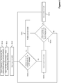
- a process for controlling a refrigeration system 300 will now be described with reference to Figure 6 .
- the refrigeration system 300 is initially switched off (the valve on the tank 12 is closed), and the first and second compartments 18, 26 are at room temperature.
- the coupling means 34 is configured to allow refrigerant to flow between the first compartment 18 and the second compartment 26.
- the coupling means 34 is arranged to prevent refrigerant from flowing to the outside of the refrigeration system 300 before it reaches the second compartment 26.
- the first fluid control means 14 is opened to allow refrigerant to flow into the first compartment 18.
- the second fluid control means 16 is closed to prevent refrigerant from flowing directly between the tank and the second compartment.
- step S602 the valve on the tank 12 is opened so that refrigerant flows via the first fluid control means 14 into the first compartment 18.
- a pump is used to pump refrigerant through the refrigeration system 300.
- the refrigeration system 300 initially operates in the first mode, as set by steps S600, S601 and S602.
- step S604 ambient temperatures of the first compartment 18 and the second compartment 26 are measured. If the ambient temperature of one compartment, but not the other, is less than or equal to a threshold specific to that compartment, then the refrigeration system 300 is configured to enter the second mode in step S606, as previously described with reference to Figure 5 . In other words, it is determined whether one of the compartments 18, 26, but not the other, has substantially reached its operating temperature while the other compartment 18, 26 has not.
- the first threshold temperature, relating to the first compartment 18, indicates that the first compartment 18 is sufficiently cool to freeze items within the first compartment 18.
- the second threshold temperature, relating to the second compartment 26, indicates that the second compartment 26 is sufficiently cool to chill items within the second compartment 26.
- the ambient temperature in some embodiments it is the temperature of the refrigerant leaving the heat exchangers 22, 30 that are compared to thresholds. In further embodiments, it is the temperatures of items within each of the compartments 18, 26 that are compared to thresholds.
- step S608 if the ambient temperature in neither of the first and second compartments 18, 26 is less than or equal to the respective threshold, then the refrigeration system 300 continues to be operated in the first mode. In other words, if the first compartment 18 and the second compartment 26 are both cooling to their respective operating temperatures, then the refrigeration system 300 operates in the first mode whereby exhausted refrigerant from the first compartment 18 is used to cool the second compartment 26.
- step S610 it is determined whether or not the ambient temperatures in both of the first compartment 18 and second compartment 26 are less than or equal to the respective first and second thresholds. In other words, it is determined whether or not both compartments 18, 26 have substantially reached their respective operating temperatures. If both compartments 18, 26 are substantially operating at their operating temperatures then at step S612 the valve on the tank 12 is turned off to prevent further refrigerant from entering the refrigeration system 200 and cooling the first compartment 18 and second compartment 26 more than necessary. In other embodiments, at step S612, the valve on the tank 12 is left open, but the first fluid control means 14 and second fluid control means 16 are closed. The valve on the tank 12 is re-opened when the ambient temperature within one or more of the compartments 18, 26 exceeds a respective threshold. This is determined in step S604.
- step S610 if the ambient temperatures within both of the first compartment 18 and second compartment 26 are not less than or equal to their respective thresholds, then S604 is repeated to determine whether the refrigeration system 300 should operate in the first mode or the second mode. Step S604 and step S610 can be repeated until the tank 12 runs out of refrigerant, or until the vehicle 1 no longer needs to cool items.
- step S610 may take place before step S604, or concurrently with step S604 in order to provide more responsive feedback.
- the refrigeration system reside in the provision of the refrigerant inlet of the second compartment 26 being coupled to the LIN exhaust outlet of the first compartment 18. This allows refrigerant to be reused, so that less refrigerant is used by the apparatus compared to prior art systems of similar size. This means small vehicles are needed, resulting in the vehicle carrying less weight. This also results in a reduced volume of refrigerant being emitted into the atmosphere from the refrigeration system.
Description
- The present invention relates to refrigeration apparatuses and methods, and in particular to the use of such apparatuses and methods for cooling compartments in a vehicle to different temperatures. More specifically, the invention relates to a refrigerated transportation system which uses a liquefied gas, such as liquid nitrogen (LIN), as the refrigerant, and to methods of supplying the refrigerant. In this context, reference can be made to
EP 1 659 355 A2 - Traditionally, the majority of the world's chilled and frozen food was transported overland in refrigerated trucks and/or trailers. The trucks and trailers were refrigerated using mechanical refrigeration units which typically used diesel to fuel a compressor which circulated a refrigerant. However, this was problematic because the diesel combustion created air pollution and carbon dioxide emissions. Additionally, the mechanical refrigeration units created noise levels of 80 decibels and above and refrigerant leakage, which could reach levels of between 15 and 35%, led to additional pollution and costs.
- Accordingly, a cryogenic replacement for the mechanical, diesel-powered truck refrigeration systems was introduced, an example of which is known as FROSTCRUISE™. FROSTCRUISE™ provides an eco-friendly solution for the transportation of perishable chilled and frozen food, based on the use of liquid nitrogen (LIN) as the refrigerant. Currently, FROSTCRUISE™ is only capable of controlling the temperature in compartment, which can be either chilled or frozen, but not both. Thus, in order to operate FROSTCRUISE™ with multi-temperature zone capability, two separate process lines, evaporators and control are required, as shown in
Figure 2 . Each compartment receives the desired flow of nitrogen to satisfy the cooling requirements of the cargo, and once the nitrogen has vaporised, the gaseous nitrogen is expelled to atmosphere thoughvalves tank 12. - Accordingly, problems associated with such known refrigeration systems are that they use a separate cooling line for each compartment that needs to be kept cool, they incur high running costs, and require a large volume of LIN to be stored, leading to a large, heavy vessel. Also on cold days, LIN is emitted that results in a vapour cloud that could obscure vision of drivers behind the vehicle. Aspects of the present invention aim to address one or more of these drawbacks.
- According to a first aspect of the present invention, there is provided a refrigeration apparatus comprising all the features of
claim 1. - Using the apparatus of the invention, it is possible to independently control the temperature in the two compartments. Furthermore, using the refrigerant expelled from the first compartment to cool the second compartment significantly reduces wastage of refrigerant. Accordingly, less refrigerant is needed, which can be contained in a smaller storage means. Furthermore, the volume of refrigerant expelled to the atmosphere is reduced, and so the extent of vapour clouds is reduced.
- The first compartment and the second compartment are configured to be at different temperatures. For example, in one embodiment, the second compartment may be configured to be colder than the first compartment. However, in a preferred embodiment, the first compartment is configured to be colder than the second compartment. The first compartment may be configured to be a freezer compartment. For example, the temperature of a freezer compartment may be less than 0°C, preferably less than 10°C, or more preferably about -20°C. The second compartment may be configured to be a chilled compartment. For example, the temperature of the chilled compartment may be greater than 0°C but less than 10°C, preferably greater than 2°C but less than 10°C, or more preferably at about 5°C.
- The second compartment comprises a refrigerant exhaust outlet by which the refrigerant is vented to the outside of the refrigeration apparatus. Preferably, the exhaust outlet of the second compartment vents refrigerant to the atmosphere. A further compartment may be coupled to the exhaust outlet of the second compartment.
- The refrigerant may comprise liquefied gas, which may be selected from a group consisting of liquid carbon dioxide, liquid argon, liquid air or liquid nitrogen. Preferably, the refrigerant comprises liquid nitrogen (LIN).
- The first compartment and the second compartment each comprise a heat exchanger. Each heat exchanger may be an evaporator.
- The refrigeration apparatus further comprises temperature sensors for measuring the temperature inside the first compartment and inside the second compartment. Each compartment comprises a temperature sensor.
- The refrigeration apparatus may comprise a pump to feed refrigerant from the refrigerant storage means to the first compartment. Refrigerant feeds from the refrigerant storage means to the first compartment along a first conduit. The refrigeration apparatus further comprises a first fluid control means, preferably on the first conduit, for controlling the rate at which refrigerant flows from the refrigerant storage means to the first compartment. Alternatively, the refrigerant storage means is a pressure vessel operating at a higher pressure than the first conduit, and so refrigerant is automatically fed along the first conduit by the pressure gradient instead of requiring a pump.
- The refrigeration apparatus may further comprise a second pump to feed refrigerant from the refrigerant storage means to the second compartment. Refrigerant feeds from the refrigerant storage means to the second compartment along a second conduit. The refrigeration apparatus further comprises a second fluid control means, preferably on the second conduit, for controlling the rate at which refrigerant flows from the refrigerant storage means to the second compartment. Alternatively, the refrigerant storage means is a pressure vessel operating at a higher pressure than the second conduit, and so refrigerant is automatically fed along the second conduit by the pressure gradient instead of requiring the second pump.
- The refrigeration apparatus comprises coupling means disposed between the first and second compartment, the coupling means being configured to temporarily prevent refrigerant from flowing between the first compartment and the second compartment, and to temporarily couple the exhaust outlet of the first compartment to the outside of the refrigeration apparatus, for example to atmosphere.
- The second fluid control means is configured to feed refrigerant into the first compartment and the second compartment at different rates when flow of refrigerant between the first compartment and the second compartment is prevented.
- The first and/or second fluid control means may each comprise a valve. The refrigeration apparatus comprises a controller for controlling the coupling means, the first fluid control means, and the second fluid control means according to the measured temperature of the first compartment and second compartment, such that the temperatures of the first compartment and second compartment are individually controllable.
- The controller is configured to control the coupling means to temporarily prevent refrigerant from flowing between the first compartment and the second compartment, and control the second fluid control means to allow refrigerant to flow into the second compartment, when the temperature of the first compartment is less than or equal to a first threshold or set-point temperature, and when the temperature of the second compartment is greater than a second threshold or set-point temperature. The first threshold temperature may indicate that the first compartment is sufficiently cool to freeze items within the compartment. For example, the first threshold temperature may be set at a temperature which is less than 0°C, preferably less than 10°C, or more preferably about -20°C. The second threshold temperature may indicate that the second compartment is sufficiently cool to chill items within the compartment. For example, the second threshold may be set at a temperature which is greater than 0°C, preferably greater than 2°C, or more preferably at about +5°C.
- The apparatus is preferably configured to control the rate at which refrigerant flows into the first compartment such that it is higher than the rate at which refrigerant flows into the second compartment when flow of refrigerant between the first compartment and the second compartment is prevented.
- The first pump may be configured to feed refrigerant into the second compartment via the second fluid control means, preferably along the second conduit. The second pump may be configured to feed refrigerant from the storage means into the second compartment, preferably along the second conduit.
- The exhaust outlet of the first compartment comprises a third fluid control means disposed between the coupling means and the outside of the refrigeration apparatus. Preferably, the third fluid control means comprises a valve.
- The refrigeration apparatus may further comprise a one-way valve disposed between the coupling means and a node coupling the first fluid control means to the exhaust outlet of the second compartment, for preventing refrigerant from flowing into the first compartment via the second fluid control means.
- According to a second aspect of the present invention, there is provided a vehicle comprising the refrigeration apparatus according to the first aspect.
- The vehicle may be, for example, a railway carriage, truck, semi-trailer, car, van, lorry, aircraft, boat or ship. The vehicle is preferably a truck.
- According to a third aspect of the present invention, there is provided a method of controlling a refrigeration apparatus according to the first aspect, the method comprising:
- feeding refrigerant from a refrigerant storage means to the first compartment via a refrigerant inlet in fluid communication with the storage means; and
- feeding refrigerant from the first compartment to the second compartment.
- Preferably, the flow rate of refrigerant to the first compartment is substantially the same as the flow rate to the second compartment.
- The method may comprise cooling the first compartment to a first temperature and cooling the second compartment to a second temperature.
- The flow rate may be selected such that the ambient temperature in the first compartment is sufficiently cool to freeze items in the first compartment, and the ambient temperature in the second compartment is sufficiently cool to chill items in the second compartment.
- The flow rate may be about 40 litres per hour.
- The refrigerant may comprise liquefied gas, which may be selected from a group consisting of liquid carbon dioxide, liquid argon, liquid air or liquid nitrogen. Preferably, the refrigerant comprises liquid nitrogen (LIN).
- The method may further comprise measuring the temperature of the first compartment and of the second compartment.
- The method may further comprise, when the temperature of the first compartment is less than or equal to a first threshold:
- configuring a coupling means to temporarily feed refrigerant from the first compartment to the outside of the refrigeration apparatus and to prevent flow of refrigerant between the first compartment and the second compartment; and
- operating a second fluid control means to feed refrigerant to flow at a different flow rate into the second compartment.
- The different flow rate may be higher than the flow rate.
- The method may further comprise, when the temperature of the first compartment is greater than the first threshold and when the temperature of the second compartment is greater than a second threshold, configuring the coupling means to feed refrigerant in the first compartment to flow into the second compartment.
- All features described herein (including any accompanying claims, abstract and drawings), and/or all of the steps of any method or process so disclosed, may be combined with any of the above aspects in any combination, except combinations where at least some of such features and/or steps are mutually exclusive.
- Embodiments of the present invention will now be described, by way of example only, with reference to the accompanying drawings, in which:
-
Figure 1 is a schematic representation of a cryogenic refrigeration vehicle located at a liquid nitrogen (LIN) filling station; -
Figure 2 is a schematic diagram showing a prior art refrigeration apparatus; -
Figure 3 shows a refrigeration system; -
Figure 4 shows an embodiment of the refrigeration system according to the invention; -
Figure 5 shows the embodiment of the refrigeration system shown inFigure 4 in a second configuration; and -
Figure 6 shows a flowchart of a process for operating a refrigeration system according to an embodiment of the present invention. - With reference to
Figure 1 , acryogenic refrigeration vehicle 1 is shown at arefrigerant filling station 2. In this embodiment, thecryogenic refrigeration vehicle 1 is an overground truck. However, thevehicle 1 may be any vehicle used to transport items that need to be kept cold. For example thecryogenic refrigeration vehicle 1 may be a train, ship, or aircraft. Thevehicle 1 comprises astorage container 10 at the rear for storing items that need to be kept cool or frozen, and arefrigeration system Figures 2 to 6 . - The
refrigeration system vehicle 1 once it has passed through therefrigeration system vehicle 1 refills at arefrigerant filling station 2, as shown inFigure 1 . The refrigerant is pumped from external tanks, such as those found buried in the ground at car fuelling stations, or tanks positioned above ground, into thevehicle 1. The refrigerant is pumped into aninternal tank 12 within thevehicle 1. - In this and later described embodiments, the refrigerant is liquid nitrogen (LIN). However, any suitable refrigerant could be used, for example, liquid helium and "dry ice".
- A
refrigeration system 100 according to the state of the art will now be described with reference toFigure 2 . Therefrigeration system 100 is installed in thestorage container 10 of avehicle 1. The LIN is stored in an insulated on-board tank 12. When it is desired to cool twodifferent compartments container 10 to two different temperatures, refrigerant (LIN) is separately and independently piped into the twocompartments compartments heat exchanger respective compartment heat exchangers - The cooling efficiency of a refrigerant is determined by the rate at which it flows through a region to be cooled. The faster the refrigerant flows, the faster it can remove heat from a region and the cooler that region will become. For example, in the prior
art refrigeration system 100 ofFigure 2 , LIN flows through thefirst compartment 18 at a rate of 40 litres per hour, and flows through thesecond compartment 26 at a rate of 20 litres per hour. When in the liquid state, nitrogen has a temperature of -196°C. Accordingly, thefirst compartment 18 is configured to be a compartment for freezing goods, when the ambient temperature is about -20°C. Thesecond compartment 18 is configured to be a compartment for chilling goods, for example when the ambient temperature is about +5°C. - After passing through the
first heat exchanger 22 disposed in the freezingcompartment 18, the LIN is expelled to the outside of thestorage container 10 to atmosphere through afirst exhaust outlet 38. Similarly, after passing through thesecond heat exchanger 30 disposed in the chilledcompartment 26, the LIN is passed to the outside of thestorage container 10 to atmosphere through asecond exhaust outlet 40. LIN enters thefirst heat exchanger 22 at a temperature of -196°C, and leaves thefirst heat exchanger 22 at a temperature of -35°C. In other words, the LIN that exits the freezingcompartment 18 is still relatively cold, and capable of being used to impart additional cooling work. However, in theprior art apparatus 100, the LIN is wasted by being exhausted to the atmosphere. Additionally, by having twoexhaust outlets vehicle 1. - Problems associated with the prior art described with reference to
Figure 2 are overcome by embodiments of the present invention. One embodiment of the present invention will now be described with reference toFigure 3 . Here, therefrigeration system 200 is installed in thestorage container 10 in the rear of avehicle 1. The LIN is stored in an insulated on-board tank 12. Thetank 12 is this embodiment is maintained at a higher pressure than the rest of the system. Therefore, when a main valve on thetank 12 is opened, LIN automatically flows into lines coupling thetank 12 to the region(s) of thestorage container 10 that need to be cooled. In other embodiments, a pump may be used to pump LIN from thetank 12 to the region(s) to be cooled. - The
storage container 10 is divided into afirst compartment 18 and asecond compartment 26, in a similar manner to as previously described with reference toFigure 2 . In this embodiment, thefirst compartment 18 is configured to be a freezer compartment and thesecond compartment 26 is configured to be a chilled compartment. - A refrigerant fluid control means 14 is disposed on the line between the
tank 12 and thefreezer compartment 18. The fluid control means 14 is this embodiment is avalve 14, which can be a solenoid valve, which is used to control the flow of refrigerant into thefreezer compartment 18. A solenoid valve is configured to be either on or off, and so either allows or prevents refrigerant flowing into the freezer compartment 18.Therefore, the fluid control means 14 may be any suitable means for allowing and preventing the flow of refrigerant. - A
first temperature sensor 20 is disposed in thefreezer compartment 18, and asecond temperature sensor 28 is disposed in the chilledcompartment 26. Thetemperature sensors temperature sensors compartment - As shown in
Figure 3 , the exhaust outlet 38' of thefreezer compartment 18 is coupled to the inlet of the chilledcompartment 26, and this allows refrigerant to be reused after passing through thefreezer compartment 18 rather than being wasted to atmosphere. However, unlike in theprior art system 100, the reused refrigerant entering thechilled compartment 26 flows at the same rate at which it flows through thefreezer compartment 18. Therefore, refrigerant flows through the chilledcompartment 26 at a higher rate than it does in theprior art system 100. Although the initial temperature of the refrigerant entering thechilled compartment 26 is greater than it would be in theprior art system 100, the increased volume passing through the chilledcompartment 26 is enough to remove excess heat energy from the chilledcompartment 26 to ensure the required temperature is achieved. - In the
refrigeration system 200 ofFigure 3 , LIN flows into, and through, thefreezer compartment 18 at a rate of 40 litres per hour. As therefrigerant system 200 is substantially lossless prior to LIN reaching the exhaust outlet 40' of the chilledcompartment 26, LIN also flows into, and through, thechilled compartment 26 at a rate of 40 litres per hour. When in the liquid state, nitrogen has a temperature of - 196°C. Therefore, the LIN reaching thefirst heat exchanger 22 is approximately at a temperature of -196°C. In order to maintain an ambient temperature of approximately -20°C within thefreezer compartment 18, on leaving thefirst heat exchanger 22, the temperature of the LIN is approximately between -35°C and -40°C. Therefore, on reaching thesecond heat exchanger 22, the temperature of the LIN is approximately between -35°C and -40°C. In order to maintain an ambient temperature of approximately +5°C within the chilledcompartment 26, on leaving thesecond heat exchanger 30, the temperature of the LIN is approximately 0°C. - Upon exiting the
second heat exchanger 30 in the chilledcompartment 26, any unevaporated LIN is expelled to the outside of thestorage container 10 to the atmosphere through a second exhaust outlet 40'. Thesecond exhaust outlet 40 includes avalve 32 for controlling the rate at which LIN is passed to the atmosphere. Thevalve 32 is a flow control valve (otherwise known as a proportional control valve); however, it would be appreciated that any suitable type of valve may be used for varying the flow of fluid through the exhaust outlet 40'. The controller may be configured to control thevalve 32 to increase or decrease the rate of flow of LIN passing through the apparatus depending on the temperature sensing result. Thevalve 32 varies the flow between 0% and 100%. Therefore the flow rate, and hence temperature of the first andsecond compartments valve 32. - As LIN has been reused in the described
refrigeration system 200, a reduced amount of LIN is exhausted into the atmosphere as compared with theprior art system 100. Accordingly, less LIN is required, and so there is a reduced vessel size requirement, resulting in the vehicle carrying less weight and bulk, and so the embodiment illustrated inFigure 3 displays significant advantages over theprior art apparatus 100, but is not part of the present invention. - However, there is a risk with the
system 200 that the twocompartments compartments Figure 4 andFigure 5 . - Referring to
Figures 4 and5 , a coupling means 34, such as a three way valve, is disposed on the line between the first (i.e. freezing)compartment 18 and the second (i.e. chilling)compartment 26. Alternatively, instead of a three way valve, the coupling means 34 may comprise two 2/2-way solenoid valves arranged to block and divert the flow of LIN accordingly. The coupling means 34 is further coupled to the outside of thestorage container 10 by exhaust outlet 38'. In other words, the coupling means 34 is configured to control the first exhaust outlet 38' to direct the flow of refrigerant from thefirst compartment 18 to either thesecond compartment 26 or to the atmosphere. Furthermore, in this embodiment, the second (i.e. chilling)compartment 26 is coupled directly to theLIN storage tank 12. The line coupling theLIN storage tank 12 to thefirst compartment 26 includes a first fluid control means 14, and the line coupling theLIN storage tank 12 and thesecond compartment 26 includes a second fluid control means 16. The first and second fluid control means 14, 16 are solenoid valves in this embodiment; however, it would be appreciated that any suitable type of valve may be used for starting or stopping the flow of refrigerant. The first and second fluid control means 14, 16 are controlled using a controller. - In one embodiment, a pump (not shown) is used to pump refrigerant from the
LIN storage tank 12 into thefirst compartment 18 and thesecond compartment 26 via the second fluid control means 16. In other embodiments, two separate pumps (not shown) are used, one for eachcompartment LIN storage tank 12 is maintained at a higher pressure than the rest of thesystem 300. The first exhaust outlet 38' includes a third fluid control means 24 for controlling the rate at which refrigerant is passed to the outside. The third fluid control means 24 is a flow control valve (otherwise known as a proportional control valve); however, it would be appreciated that any suitable type of valve may be used for varying the flow rate of refrigerant to the atmosphere. Therefore, the third fluid control means can be used to control the temperature of thefirst compartment 18 when the temperatures of thecompartments - The
temperature sensors compartment refrigeration system 300 to be in a first mode if the temperature in eachcompartment compartment compartment - In other words, when it is desired to cool two
different compartments refrigeration system 300 is operated in the first mode. If one compartment reaches its operating temperature while the other compartment is still cooling from the first temperature to its operating temperature, then therefrigeration system 300 is operated in the second mode so that the compartment undergoing cooling cools faster, and the compartment at the operating temperature does not become too cold. Therefrigeration apparatus 300 can be switched between the first and second modes as many times as is necessary to maintain the operating temperatures in eachcompartment - The operating temperature of the
first compartment 18 is sufficient to freeze items within thefirst compartment 18. For example, the operating temperature of thefirst compartment 18 is -20°C. The operating temperature of thesecond compartment 26 is sufficient to chill items within thesecond compartment 26. For example, the operating temperature of thesecond compartment 26 is +5°C. When the temperatures of bothcompartments LIN storage tank 12. The flow is reactivated when the temperature of one or bothcompartments - A one-
way valve 36 is disposed between the coupling means 34 and a node coupling a conduit comprising the second fluid control means 16 to thesecond compartment 26, for preventing refrigerant from flowing into thefirst compartment 18 via the second fluid control means 16. The one-way valve 36 in this embodiment is a check valve, although it will be appreciated that other types of valves may be used for preventing backflow of refrigerant. - In other embodiments, the exhaust outlet 38' of the
first compartment 18 and the line coupling thetank 12 to thesecond heat exchanger 30 are not coupled together at the node. In these embodiments, the one-way valve 36 is not necessary. In other words, in these embodiments, thesecond compartment 26 has two input lines. - A further one-way valve may be disposed in the conduit comprising the second fluid control means 16, to prevent refrigerant from flowing from the
first compartment 18 back to thetank 12 instead of into thesecond compartment 26. - In the first mode, shown in
Figure 4 , the first fluid control means (valve) 14 is opened to allow refrigerant to flow from thetank 12 to the first (freezer)compartment 18. Thesecond valve 16 is closed to prevent refrigerant from flowing directly into the second (chiller) compartment from thetank 12. Thevalve 34 is arranged to allow refrigerant to flow from the first (freezer)compartment 18 to the second (chiller)compartment 26. As such, thevalve 34 prevents refrigerant being exhausted outside of thestorage compartment 10 before reaching thesecond compartment 26. - In the second mode, shown in
Figure 5 , the temperature of each of the first andsecond compartments first valve 14 is opened to allow refrigerant to flow from thetank 12 to the first (freezer)compartment 18. Thevalve 16 is opened to allow refrigerant to flow directly into the second (chiller) compartment from thetank 12. Alternatively, one of the first andsecond valves compartments - The
valve 34 is arranged to stop refrigerant from flowing from the first (freezer)compartment 18 to the second (chiller)compartment 26. Instead, thevalve 34 allows refrigerant to be exhausted outside of thestorage compartment 10 before reaching thesecond compartment 26. - In a further embodiment, in the second mode, the
refrigeration system 300 is configured to allow refrigerant to flow from the first compartment (18) to thesecond compartment 26, in addition to allowing refrigerant to flow from thetank 12 into thesecond compartment 26 directly via thesecond valve 16. This provides a "boost" to the cooling efficiency of theheat exchanger 30 in thesecond compartment 26. In this embodiment, thesecond compartment 26 is cooled both by reused refrigerant, and refrigerant supplied directly from thetank 12. In this embodiment, thesecond compartment 26 can be cooled quickly, while not using as much refrigerant as the second mode described in relation to previous embodiments. - A process for controlling a
refrigeration system 300 according to the embodiments described inFigures 4 and5 will now be described with reference toFigure 6 . Here, it is assumed that therefrigeration system 300 is initially switched off (the valve on thetank 12 is closed), and the first andsecond compartments first compartment 18 and thesecond compartment 26. The coupling means 34 is arranged to prevent refrigerant from flowing to the outside of therefrigeration system 300 before it reaches thesecond compartment 26. In step S601, the first fluid control means 14 is opened to allow refrigerant to flow into thefirst compartment 18. The second fluid control means 16 is closed to prevent refrigerant from flowing directly between the tank and the second compartment. - In step S602, the valve on the
tank 12 is opened so that refrigerant flows via the first fluid control means 14 into thefirst compartment 18. In other embodiments, a pump is used to pump refrigerant through therefrigeration system 300. In other words, therefrigeration system 300 initially operates in the first mode, as set by steps S600, S601 and S602. - At step S604, ambient temperatures of the
first compartment 18 and thesecond compartment 26 are measured. If the ambient temperature of one compartment, but not the other, is less than or equal to a threshold specific to that compartment, then therefrigeration system 300 is configured to enter the second mode in step S606, as previously described with reference toFigure 5 . In other words, it is determined whether one of thecompartments other compartment - For example, the first threshold temperature, relating to the
first compartment 18, indicates that thefirst compartment 18 is sufficiently cool to freeze items within thefirst compartment 18. The second threshold temperature, relating to thesecond compartment 26, indicates that thesecond compartment 26 is sufficiently cool to chill items within thesecond compartment 26. Alternatively to the ambient temperature, in some embodiments it is the temperature of the refrigerant leaving theheat exchangers compartments - In step S608, if the ambient temperature in neither of the first and
second compartments refrigeration system 300 continues to be operated in the first mode. In other words, if thefirst compartment 18 and thesecond compartment 26 are both cooling to their respective operating temperatures, then therefrigeration system 300 operates in the first mode whereby exhausted refrigerant from thefirst compartment 18 is used to cool thesecond compartment 26. - At step S610 it is determined whether or not the ambient temperatures in both of the
first compartment 18 andsecond compartment 26 are less than or equal to the respective first and second thresholds. In other words, it is determined whether or not bothcompartments tank 12 is turned off to prevent further refrigerant from entering therefrigeration system 200 and cooling thefirst compartment 18 andsecond compartment 26 more than necessary. In other embodiments, at step S612, the valve on thetank 12 is left open, but the first fluid control means 14 and second fluid control means 16 are closed. The valve on thetank 12 is re-opened when the ambient temperature within one or more of thecompartments - Further in step S610, if the ambient temperatures within both of the
first compartment 18 andsecond compartment 26 are not less than or equal to their respective thresholds, then S604 is repeated to determine whether therefrigeration system 300 should operate in the first mode or the second mode. Step S604 and step S610 can be repeated until thetank 12 runs out of refrigerant, or until thevehicle 1 no longer needs to cool items. - It would be readily understood that this is just one example of the way in which the
refrigeration system 300 operates. In some embodiments, step S610 may take place before step S604, or concurrently with step S604 in order to provide more responsive feedback. - Advantages of the refrigeration system reside in the provision of the refrigerant inlet of the
second compartment 26 being coupled to the LIN exhaust outlet of thefirst compartment 18. This allows refrigerant to be reused, so that less refrigerant is used by the apparatus compared to prior art systems of similar size. This means small vehicles are needed, resulting in the vehicle carrying less weight. This also results in a reduced volume of refrigerant being emitted into the atmosphere from the refrigeration system.
Claims (18)
- A refrigeration apparatus (300) comprising:- refrigerant storage means (12);- a first compartment (18) comprising a refrigerant inlet in fluid communication with the refrigerant storage means (12) and a refrigerant exhaust outlet (38'); and- a second compartment (26) comprising a refrigerant inlet in fluid communication with the refrigerant exhaust outlet (38') of the first compartment (18), wherein the refrigeration apparatus (300) is configured to feed a refrigerant from the refrigerant storage means (12) to the second compartment (26) via the first compartment (18), wherein the second compartment (26) comprises a refrigerant exhaust outlet (40') by which the refrigerant is vented to the outside of the refrigeration apparatus (300),wherein the first compartment (18) and the second compartment (26) are configured to be at different temperatures,
wherein the first compartment (18) and the second compartment (26) each comprise a heat exchanger (22, 30),
the refrigeration apparatus (300) further comprising:- a first fluid control means (14) for controlling the rate at which refrigerant flows from the refrigerant storage means (12) along a first conduit to the first compartment (18);- a second fluid control means (16) for controlling the rate at which refrigerant flows from the refrigerant storage means (12) along a second conduit to the second compartment (26);- temperature sensors (20, 28) for measuring the temperature inside the first compartment (18) and inside the second compartment (26); and- coupling means (34) disposed between the first compartment (18) and the second compartment (26), wherein the coupling means (34) is configured to temporarily prevent refrigerant from flowing between the first compartment (18) and the second compartment (26), and to temporarily couple the exhaust outlet (38') of the first compartment (18) to the outside of the refrigeration apparatus (300), wherein the first fluid control means (14) and the second fluid control means (16) are configured to feed refrigerant into the first compartment (18) and into the second compartment (26) at different rates when flow of refrigerant between the first compartment (18) and the second compartment (26) is prevented; and- a controller for controlling the coupling means (34), the first fluid control means (14), and the second fluid control means (16) according to the measured temperature of the first compartment (18) and second compartment (26), such that the temperatures of the first compartment (18) and second compartment (26) are individually controllable, wherein the controller is configured to control the coupling means (34) to temporarily prevent refrigerant from flowing between the first compartment (18) and the second compartment (26), and control the second fluid control means (16) to allow refrigerant to flow into the second compartment (26), when the temperature of the first compartment (18) is less than or equal to a first threshold or set-point temperature, and when the temperature of the second compartment (26) is greater than a second threshold or set-point temperature, wherein the exhaust outlet (38') of the first compartment (18) comprises a third fluid control means (24) disposed between the coupling means (34) and the outside of the refrigeration apparatus (300). - The refrigeration apparatus according to claim 1,- wherein the temperature of the first compartment (18) is configured to be less than 0°C, or less than 10°C, or about -20°C; and- wherein the temperature of the second compartment (26) is configured to be greater than 0°C but less than 10°C, or greater than 2°C but less than 10°C, or at about 5°C.
- The refrigeration apparatus according to claim 1 or 2, wherein the refrigerant comprises liquefied gas.
- The refrigeration apparatus according to any one of the preceding claims, further comprising a pump to feed refrigerant from the refrigerant storage means (12) to the first compartment (18).
- The refrigeration apparatus according to any one of the preceding claims, further comprising a second pump to feed refrigerant from the refrigerant storage means (12) to the second compartment (26).
- The refrigeration apparatus according to any one of the preceding claims, wherein the controller is configured to control the rate at which refrigerant flows into the first compartment (18) such that it is higher than the rate at which refrigerant flows into the second compartment (26) when flow of refrigerant between the first compartment (18) and the second compartment (26) is prevented.
- The refrigeration apparatus according to any one of the preceding claims, further comprising a one-way valve (36) disposed between the coupling means (34) and a node coupling the first fluid control means (14) to the exhaust outlet (40') of the second chamber (26), for preventing refrigerant from flowing into the first compartment (18) via the second fluid control means (16).
- A vehicle (10) comprising the refrigeration apparatus (300) according to any one of the preceding claims.
- A method of controlling a refrigeration apparatus (300) according to any one of the preceding claims, the method comprising:- feeding a refrigerant from a refrigerant storage means (12) to the first compartment (18) via a refrigerant inlet in fluid communication with the refrigerant storage means (12); and- feeding refrigerant from the first compartment (18) to the second compartment (26).
- The method according to claim 9, wherein the flow rate of refrigerant to the first compartment (18) is substantially the same as the flow rate to the second compartment (26).
- The method according to claim 9 or 10, further comprising- cooling the first compartment (18) to a first temperature, and- cooling the second compartment (26) to a second temperature.
- The method according claim 11, wherein the flow rate is selected such that- the ambient temperature in the first compartment (18) is sufficiently cool to freeze items in the first compartment (18), and- the ambient temperature in the second compartment (26) is sufficiently cool to chill items in the second compartment (26).
- The method according to claim 12, wherein the flow rate is about 40 litres per hour.
- The method according to any one of claims 9 to 13, wherein the refrigerant comprises liquefied gas.
- The method according to any one of claims 9 to 14, further comprising measuring the temperature of the first compartment (18) and of the second compartment (26).
- The method according to claim 15, further comprising, when the temperature of the first compartment (18) is less than or equal to a first threshold:- configuring a coupling means (34) to temporarily feed refrigerant from the first compartment (18) to the outside of the refrigeration apparatus (300) and to prevent flow of refrigerant between the first compartment (18) and the second compartment (26); and- operating a second fluid control means (16) to feed refrigerant to flow at a different flow rate into the second compartment (26).
- The method according to claim 16, wherein the different flow rate is higher than the flow rate.
- The method according to claim 16 or 17, further comprising, when the temperature of the first compartment (18) is greater than the first threshold and when the temperature of the second compartment (26) is greater than a second threshold, configuring the coupling means (34) to feed refrigerant in the first compartment (18) to flow into the second compartment (26).
Applications Claiming Priority (1)
| Application Number | Priority Date | Filing Date | Title |
|---|---|---|---|
| GB1516982.4A GB2542604A (en) | 2015-09-25 | 2015-09-25 | Refrigeration apparatus |
Publications (2)
| Publication Number | Publication Date |
|---|---|
| EP3147600A1 EP3147600A1 (en) | 2017-03-29 |
| EP3147600B1 true EP3147600B1 (en) | 2020-08-26 |
Family
ID=54544108
Family Applications (1)
| Application Number | Title | Priority Date | Filing Date |
|---|---|---|---|
| EP16190676.3A Active EP3147600B1 (en) | 2015-09-25 | 2016-09-26 | Refrigeration apparatus |
Country Status (2)
| Country | Link |
|---|---|
| EP (1) | EP3147600B1 (en) |
| GB (1) | GB2542604A (en) |
Families Citing this family (4)
| Publication number | Priority date | Publication date | Assignee | Title |
|---|---|---|---|---|
| US10047978B1 (en) * | 2017-09-19 | 2018-08-14 | Reflect Scientific Inc. | ULT freezer with heater |
| US20230068459A1 (en) * | 2020-02-18 | 2023-03-02 | Mbda Uk Limited | An assembly and method for cooling an apparatus |
| EP3869121A1 (en) * | 2020-02-18 | 2021-08-25 | MBDA UK Limited | An assembly and method for cooling an apparatus |
| DE102021003305A1 (en) * | 2021-06-25 | 2022-12-29 | Messer Se & Co. Kgaa | Method of operating a refrigerated vehicle and refrigerated vehicle |
Citations (2)
| Publication number | Priority date | Publication date | Assignee | Title |
|---|---|---|---|---|
| US3068105A (en) * | 1960-10-26 | 1962-12-11 | Liquefreeze Company Inc | Method of preparing a frozen food product |
| WO2010016758A1 (en) * | 2008-08-04 | 2010-02-11 | Toeca International Company B.V. | Device and method for dosing cooling medium for the purpose of cooling drinks |
Family Cites Families (9)
| Publication number | Priority date | Publication date | Assignee | Title |
|---|---|---|---|---|
| GB636618A (en) * | 1946-08-30 | 1950-05-03 | Gen Motors Corp | Improved refrigeration apparatus |
| US5267446A (en) * | 1992-11-27 | 1993-12-07 | Thermo King Corp. | Air conditioning and refrigeration systems utilizing a cryogen |
| EP1593918B1 (en) * | 2004-05-06 | 2013-03-13 | Air Liquide Deutschland GmbH | Indirect cooling of refrigerated vehicles |
| EP1659355A3 (en) * | 2004-11-17 | 2008-02-13 | Air Liquide Deutschland GmbH | Cooling process and cooling apparatus for refrigerated vehicles |
| EP2437008B1 (en) * | 2010-10-04 | 2018-07-04 | Whirlpool Corporation | Refrigeration appliance with two evaporators in series and method for controlling such appliance |
| EP2763865B1 (en) * | 2011-10-03 | 2017-08-30 | Volvo Lastvagnar Ab | Truck with a refrigerated compartment |
| DE102012206806A1 (en) * | 2012-04-25 | 2013-10-31 | BSH Bosch und Siemens Hausgeräte GmbH | Single-circuit refrigeration unit and operating method for this |
| GB2508017A (en) * | 2012-11-19 | 2014-05-21 | Dearman Engine Company Ltd | A cryogenic engine driven refrigeration system |
| CN104677011B (en) * | 2015-03-13 | 2017-09-19 | 合肥华凌股份有限公司 | Refrigerator |
-
2015
- 2015-09-25 GB GB1516982.4A patent/GB2542604A/en not_active Withdrawn
-
2016
- 2016-09-26 EP EP16190676.3A patent/EP3147600B1/en active Active
Patent Citations (2)
| Publication number | Priority date | Publication date | Assignee | Title |
|---|---|---|---|---|
| US3068105A (en) * | 1960-10-26 | 1962-12-11 | Liquefreeze Company Inc | Method of preparing a frozen food product |
| WO2010016758A1 (en) * | 2008-08-04 | 2010-02-11 | Toeca International Company B.V. | Device and method for dosing cooling medium for the purpose of cooling drinks |
Also Published As
| Publication number | Publication date |
|---|---|
| EP3147600A1 (en) | 2017-03-29 |
| GB201516982D0 (en) | 2015-11-11 |
| GB2542604A (en) | 2017-03-29 |
Similar Documents
| Publication | Publication Date | Title |
|---|---|---|
| EP3147600B1 (en) | Refrigeration apparatus | |
| EP3452315B1 (en) | Integrated compressed gas transport refrigeration unit for compressed gas fueled vehicles | |
| US6698212B2 (en) | Cryogenic temperature control apparatus and method | |
| US6631621B2 (en) | Cryogenic temperature control apparatus and method | |
| US9688181B2 (en) | Control method for a hybrid refrigeration system | |
| RU2228495C1 (en) | Cooling method for vehicle adapted for food transportation with the use of liquid nitrogen | |
| US6895764B2 (en) | Environmentally friendly method and apparatus for cooling a temperature controlled space | |
| EP1145089B1 (en) | Hybrid temperature control system | |
| EP3010754B1 (en) | Hybrid temperature control system and method | |
| US6751966B2 (en) | Hybrid temperature control system | |
| CN101668682B (en) | Cooling system and freight container for cooling cargo on airplane | |
| EP2847528B1 (en) | Supply air discharge for a refrigerated container | |
| US20210116156A1 (en) | Transport climate control system with auxilary cooling | |
| EP3147599A1 (en) | Refrigeration apparatus | |
| US6024074A (en) | Refrigerated fuel for engines | |
| US20160144763A1 (en) | Eutectic device for a transport refrigeration system and methods for cooling and installing the eutectic device | |
| US3757531A (en) | Refrigeration apparatus employing liquified gas | |
| WO2012176075A2 (en) | Methods for transportation of thermally unstable products | |
| CN108700358A (en) | The power management of carbon dioxide transport refrigeration system | |
| CN110254340B (en) | Portable liquid nitrogen-based refrigeration system for transporting refrigerated goods | |
| DK2711601T3 (en) | Process for filling a refrigerant tank in a refrigerator and refrigerator | |
| US20210268877A1 (en) | Multi-temperature transport refrigeration system and method | |
| EP3147144A1 (en) | Heat exchange apparatus and corresponding method | |
| CN201659919U (en) | Double-temperature double-car refrigerator van | |
| CN117480061A (en) | Method for operating a refrigerated vehicle and refrigerated vehicle |
Legal Events
| Date | Code | Title | Description |
|---|---|---|---|
| PUAI | Public reference made under article 153(3) epc to a published international application that has entered the european phase |
Free format text: ORIGINAL CODE: 0009012 |
|
| STAA | Information on the status of an ep patent application or granted ep patent |
Free format text: STATUS: THE APPLICATION HAS BEEN PUBLISHED |
|
| AK | Designated contracting states |
Kind code of ref document: A1 Designated state(s): AL AT BE BG CH CY CZ DE DK EE ES FI FR GB GR HR HU IE IS IT LI LT LU LV MC MK MT NL NO PL PT RO RS SE SI SK SM TR |
|
| AX | Request for extension of the european patent |
Extension state: BA ME |
|
| RIN1 | Information on inventor provided before grant (corrected) |
Inventor name: ALLWOOD, MICHAEL |
|
| STAA | Information on the status of an ep patent application or granted ep patent |
Free format text: STATUS: REQUEST FOR EXAMINATION WAS MADE |
|
| 17P | Request for examination filed |
Effective date: 20170929 |
|
| RBV | Designated contracting states (corrected) |
Designated state(s): AL AT BE BG CH CY CZ DE DK EE ES FI FR GB GR HR HU IE IS IT LI LT LU LV MC MK MT NL NO PL PT RO RS SE SI SK SM TR |
|
| STAA | Information on the status of an ep patent application or granted ep patent |
Free format text: STATUS: EXAMINATION IS IN PROGRESS |
|
| 17Q | First examination report despatched |
Effective date: 20180227 |
|
| GRAP | Despatch of communication of intention to grant a patent |
Free format text: ORIGINAL CODE: EPIDOSNIGR1 |
|
| STAA | Information on the status of an ep patent application or granted ep patent |
Free format text: STATUS: GRANT OF PATENT IS INTENDED |
|
| INTG | Intention to grant announced |
Effective date: 20191021 |
|
| GRAJ | Information related to disapproval of communication of intention to grant by the applicant or resumption of examination proceedings by the epo deleted |
Free format text: ORIGINAL CODE: EPIDOSDIGR1 |
|
| STAA | Information on the status of an ep patent application or granted ep patent |
Free format text: STATUS: EXAMINATION IS IN PROGRESS |
|
| GRAP | Despatch of communication of intention to grant a patent |
Free format text: ORIGINAL CODE: EPIDOSNIGR1 |
|
| STAA | Information on the status of an ep patent application or granted ep patent |
Free format text: STATUS: GRANT OF PATENT IS INTENDED |
|
| INTG | Intention to grant announced |
Effective date: 20200317 |
|
| RAP1 | Party data changed (applicant data changed or rights of an application transferred) |
Owner name: LINDE GMBH |
|
| GRAS | Grant fee paid |
Free format text: ORIGINAL CODE: EPIDOSNIGR3 |
|
| GRAA | (expected) grant |
Free format text: ORIGINAL CODE: 0009210 |
|
| STAA | Information on the status of an ep patent application or granted ep patent |
Free format text: STATUS: THE PATENT HAS BEEN GRANTED |
|
| AK | Designated contracting states |
Kind code of ref document: B1 Designated state(s): AL AT BE BG CH CY CZ DE DK EE ES FI FR GB GR HR HU IE IS IT LI LT LU LV MC MK MT NL NO PL PT RO RS SE SI SK SM TR |
|
| REG | Reference to a national code |
Ref country code: GB Ref legal event code: FG4D |
|
| REG | Reference to a national code |
Ref country code: CH Ref legal event code: EP |
|
| REG | Reference to a national code |
Ref country code: AT Ref legal event code: REF Ref document number: 1306778 Country of ref document: AT Kind code of ref document: T Effective date: 20200915 |
|
| REG | Reference to a national code |
Ref country code: IE Ref legal event code: FG4D |
|
| REG | Reference to a national code |
Ref country code: DE Ref legal event code: R096 Ref document number: 602016042644 Country of ref document: DE |
|
| REG | Reference to a national code |
Ref country code: LT Ref legal event code: MG4D |
|
| PG25 | Lapsed in a contracting state [announced via postgrant information from national office to epo] |
Ref country code: FI Free format text: LAPSE BECAUSE OF FAILURE TO SUBMIT A TRANSLATION OF THE DESCRIPTION OR TO PAY THE FEE WITHIN THE PRESCRIBED TIME-LIMIT Effective date: 20200826 Ref country code: GR Free format text: LAPSE BECAUSE OF FAILURE TO SUBMIT A TRANSLATION OF THE DESCRIPTION OR TO PAY THE FEE WITHIN THE PRESCRIBED TIME-LIMIT Effective date: 20201127 Ref country code: NO Free format text: LAPSE BECAUSE OF FAILURE TO SUBMIT A TRANSLATION OF THE DESCRIPTION OR TO PAY THE FEE WITHIN THE PRESCRIBED TIME-LIMIT Effective date: 20201126 Ref country code: HR Free format text: LAPSE BECAUSE OF FAILURE TO SUBMIT A TRANSLATION OF THE DESCRIPTION OR TO PAY THE FEE WITHIN THE PRESCRIBED TIME-LIMIT Effective date: 20200826 Ref country code: LT Free format text: LAPSE BECAUSE OF FAILURE TO SUBMIT A TRANSLATION OF THE DESCRIPTION OR TO PAY THE FEE WITHIN THE PRESCRIBED TIME-LIMIT Effective date: 20200826 Ref country code: BG Free format text: LAPSE BECAUSE OF FAILURE TO SUBMIT A TRANSLATION OF THE DESCRIPTION OR TO PAY THE FEE WITHIN THE PRESCRIBED TIME-LIMIT Effective date: 20201126 Ref country code: SE Free format text: LAPSE BECAUSE OF FAILURE TO SUBMIT A TRANSLATION OF THE DESCRIPTION OR TO PAY THE FEE WITHIN THE PRESCRIBED TIME-LIMIT Effective date: 20200826 Ref country code: PT Free format text: LAPSE BECAUSE OF FAILURE TO SUBMIT A TRANSLATION OF THE DESCRIPTION OR TO PAY THE FEE WITHIN THE PRESCRIBED TIME-LIMIT Effective date: 20201228 |
|
| REG | Reference to a national code |
Ref country code: NL Ref legal event code: MP Effective date: 20200826 |
|
| REG | Reference to a national code |
Ref country code: AT Ref legal event code: MK05 Ref document number: 1306778 Country of ref document: AT Kind code of ref document: T Effective date: 20200826 |
|
| PG25 | Lapsed in a contracting state [announced via postgrant information from national office to epo] |
Ref country code: PL Free format text: LAPSE BECAUSE OF FAILURE TO SUBMIT A TRANSLATION OF THE DESCRIPTION OR TO PAY THE FEE WITHIN THE PRESCRIBED TIME-LIMIT Effective date: 20200826 Ref country code: NL Free format text: LAPSE BECAUSE OF FAILURE TO SUBMIT A TRANSLATION OF THE DESCRIPTION OR TO PAY THE FEE WITHIN THE PRESCRIBED TIME-LIMIT Effective date: 20200826 Ref country code: LV Free format text: LAPSE BECAUSE OF FAILURE TO SUBMIT A TRANSLATION OF THE DESCRIPTION OR TO PAY THE FEE WITHIN THE PRESCRIBED TIME-LIMIT Effective date: 20200826 Ref country code: RS Free format text: LAPSE BECAUSE OF FAILURE TO SUBMIT A TRANSLATION OF THE DESCRIPTION OR TO PAY THE FEE WITHIN THE PRESCRIBED TIME-LIMIT Effective date: 20200826 Ref country code: IS Free format text: LAPSE BECAUSE OF FAILURE TO SUBMIT A TRANSLATION OF THE DESCRIPTION OR TO PAY THE FEE WITHIN THE PRESCRIBED TIME-LIMIT Effective date: 20201226 |
|
| PG25 | Lapsed in a contracting state [announced via postgrant information from national office to epo] |
Ref country code: EE Free format text: LAPSE BECAUSE OF FAILURE TO SUBMIT A TRANSLATION OF THE DESCRIPTION OR TO PAY THE FEE WITHIN THE PRESCRIBED TIME-LIMIT Effective date: 20200826 Ref country code: RO Free format text: LAPSE BECAUSE OF FAILURE TO SUBMIT A TRANSLATION OF THE DESCRIPTION OR TO PAY THE FEE WITHIN THE PRESCRIBED TIME-LIMIT Effective date: 20200826 Ref country code: SM Free format text: LAPSE BECAUSE OF FAILURE TO SUBMIT A TRANSLATION OF THE DESCRIPTION OR TO PAY THE FEE WITHIN THE PRESCRIBED TIME-LIMIT Effective date: 20200826 Ref country code: DK Free format text: LAPSE BECAUSE OF FAILURE TO SUBMIT A TRANSLATION OF THE DESCRIPTION OR TO PAY THE FEE WITHIN THE PRESCRIBED TIME-LIMIT Effective date: 20200826 Ref country code: CZ Free format text: LAPSE BECAUSE OF FAILURE TO SUBMIT A TRANSLATION OF THE DESCRIPTION OR TO PAY THE FEE WITHIN THE PRESCRIBED TIME-LIMIT Effective date: 20200826 |
|
| REG | Reference to a national code |
Ref country code: CH Ref legal event code: PL |
|
| REG | Reference to a national code |
Ref country code: DE Ref legal event code: R097 Ref document number: 602016042644 Country of ref document: DE |
|
| PG25 | Lapsed in a contracting state [announced via postgrant information from national office to epo] |
Ref country code: ES Free format text: LAPSE BECAUSE OF FAILURE TO SUBMIT A TRANSLATION OF THE DESCRIPTION OR TO PAY THE FEE WITHIN THE PRESCRIBED TIME-LIMIT Effective date: 20200826 Ref country code: AL Free format text: LAPSE BECAUSE OF FAILURE TO SUBMIT A TRANSLATION OF THE DESCRIPTION OR TO PAY THE FEE WITHIN THE PRESCRIBED TIME-LIMIT Effective date: 20200826 Ref country code: AT Free format text: LAPSE BECAUSE OF FAILURE TO SUBMIT A TRANSLATION OF THE DESCRIPTION OR TO PAY THE FEE WITHIN THE PRESCRIBED TIME-LIMIT Effective date: 20200826 Ref country code: MC Free format text: LAPSE BECAUSE OF FAILURE TO SUBMIT A TRANSLATION OF THE DESCRIPTION OR TO PAY THE FEE WITHIN THE PRESCRIBED TIME-LIMIT Effective date: 20200826 |
|
| REG | Reference to a national code |
Ref country code: BE Ref legal event code: MM Effective date: 20200930 |
|
| PG25 | Lapsed in a contracting state [announced via postgrant information from national office to epo] |
Ref country code: LU Free format text: LAPSE BECAUSE OF NON-PAYMENT OF DUE FEES Effective date: 20200926 Ref country code: SK Free format text: LAPSE BECAUSE OF FAILURE TO SUBMIT A TRANSLATION OF THE DESCRIPTION OR TO PAY THE FEE WITHIN THE PRESCRIBED TIME-LIMIT Effective date: 20200826 |
|
| PLBE | No opposition filed within time limit |
Free format text: ORIGINAL CODE: 0009261 |
|
| STAA | Information on the status of an ep patent application or granted ep patent |
Free format text: STATUS: NO OPPOSITION FILED WITHIN TIME LIMIT |
|
| PG25 | Lapsed in a contracting state [announced via postgrant information from national office to epo] |
Ref country code: IT Free format text: LAPSE BECAUSE OF FAILURE TO SUBMIT A TRANSLATION OF THE DESCRIPTION OR TO PAY THE FEE WITHIN THE PRESCRIBED TIME-LIMIT Effective date: 20200826 |
|
| 26N | No opposition filed |
Effective date: 20210527 |
|
| PG25 | Lapsed in a contracting state [announced via postgrant information from national office to epo] |
Ref country code: SI Free format text: LAPSE BECAUSE OF FAILURE TO SUBMIT A TRANSLATION OF THE DESCRIPTION OR TO PAY THE FEE WITHIN THE PRESCRIBED TIME-LIMIT Effective date: 20200826 Ref country code: LI Free format text: LAPSE BECAUSE OF NON-PAYMENT OF DUE FEES Effective date: 20200930 Ref country code: IE Free format text: LAPSE BECAUSE OF NON-PAYMENT OF DUE FEES Effective date: 20200926 Ref country code: BE Free format text: LAPSE BECAUSE OF NON-PAYMENT OF DUE FEES Effective date: 20200930 Ref country code: CH Free format text: LAPSE BECAUSE OF NON-PAYMENT OF DUE FEES Effective date: 20200930 |
|
| PG25 | Lapsed in a contracting state [announced via postgrant information from national office to epo] |
Ref country code: TR Free format text: LAPSE BECAUSE OF FAILURE TO SUBMIT A TRANSLATION OF THE DESCRIPTION OR TO PAY THE FEE WITHIN THE PRESCRIBED TIME-LIMIT Effective date: 20200826 Ref country code: MT Free format text: LAPSE BECAUSE OF FAILURE TO SUBMIT A TRANSLATION OF THE DESCRIPTION OR TO PAY THE FEE WITHIN THE PRESCRIBED TIME-LIMIT Effective date: 20200826 Ref country code: CY Free format text: LAPSE BECAUSE OF FAILURE TO SUBMIT A TRANSLATION OF THE DESCRIPTION OR TO PAY THE FEE WITHIN THE PRESCRIBED TIME-LIMIT Effective date: 20200826 |
|
| PG25 | Lapsed in a contracting state [announced via postgrant information from national office to epo] |
Ref country code: MK Free format text: LAPSE BECAUSE OF FAILURE TO SUBMIT A TRANSLATION OF THE DESCRIPTION OR TO PAY THE FEE WITHIN THE PRESCRIBED TIME-LIMIT Effective date: 20200826 |
|
| PGFP | Annual fee paid to national office [announced via postgrant information from national office to epo] |
Ref country code: GB Payment date: 20220927 Year of fee payment: 7 |
|
| PGFP | Annual fee paid to national office [announced via postgrant information from national office to epo] |
Ref country code: FR Payment date: 20230918 Year of fee payment: 8 Ref country code: DE Payment date: 20230919 Year of fee payment: 8 |