EP2437008B1 - Refrigeration appliance with two evaporators in series and method for controlling such appliance - Google Patents
Refrigeration appliance with two evaporators in series and method for controlling such appliance Download PDFInfo
- Publication number
- EP2437008B1 EP2437008B1 EP10186438.7A EP10186438A EP2437008B1 EP 2437008 B1 EP2437008 B1 EP 2437008B1 EP 10186438 A EP10186438 A EP 10186438A EP 2437008 B1 EP2437008 B1 EP 2437008B1
- Authority
- EP
- European Patent Office
- Prior art keywords
- evaporator
- fresh food
- fan
- compressor
- freezer
- Prior art date
- Legal status (The legal status is an assumption and is not a legal conclusion. Google has not performed a legal analysis and makes no representation as to the accuracy of the status listed.)
- Active
Links
- 238000005057 refrigeration Methods 0.000 title claims description 24
- 238000000034 method Methods 0.000 title claims description 9
- 238000001816 cooling Methods 0.000 claims description 7
- 239000003507 refrigerant Substances 0.000 description 6
- 238000011144 upstream manufacturing Methods 0.000 description 5
- 230000008901 benefit Effects 0.000 description 2
- 238000010586 diagram Methods 0.000 description 2
- 238000007664 blowing Methods 0.000 description 1
- 230000003111 delayed effect Effects 0.000 description 1
- 238000005265 energy consumption Methods 0.000 description 1
- 238000001704 evaporation Methods 0.000 description 1
- 230000008020 evaporation Effects 0.000 description 1
- 238000009920 food preservation Methods 0.000 description 1
- 239000007788 liquid Substances 0.000 description 1
- 230000001052 transient effect Effects 0.000 description 1
Images

Classifications
-
- F—MECHANICAL ENGINEERING; LIGHTING; HEATING; WEAPONS; BLASTING
- F25—REFRIGERATION OR COOLING; COMBINED HEATING AND REFRIGERATION SYSTEMS; HEAT PUMP SYSTEMS; MANUFACTURE OR STORAGE OF ICE; LIQUEFACTION SOLIDIFICATION OF GASES
- F25B—REFRIGERATION MACHINES, PLANTS OR SYSTEMS; COMBINED HEATING AND REFRIGERATION SYSTEMS; HEAT PUMP SYSTEMS
- F25B5/00—Compression machines, plants or systems, with several evaporator circuits, e.g. for varying refrigerating capacity
- F25B5/04—Compression machines, plants or systems, with several evaporator circuits, e.g. for varying refrigerating capacity arranged in series
-
- F—MECHANICAL ENGINEERING; LIGHTING; HEATING; WEAPONS; BLASTING
- F25—REFRIGERATION OR COOLING; COMBINED HEATING AND REFRIGERATION SYSTEMS; HEAT PUMP SYSTEMS; MANUFACTURE OR STORAGE OF ICE; LIQUEFACTION SOLIDIFICATION OF GASES
- F25B—REFRIGERATION MACHINES, PLANTS OR SYSTEMS; COMBINED HEATING AND REFRIGERATION SYSTEMS; HEAT PUMP SYSTEMS
- F25B49/00—Arrangement or mounting of control or safety devices
- F25B49/02—Arrangement or mounting of control or safety devices for compression type machines, plants or systems
- F25B49/022—Compressor control arrangements
-
- F—MECHANICAL ENGINEERING; LIGHTING; HEATING; WEAPONS; BLASTING
- F25—REFRIGERATION OR COOLING; COMBINED HEATING AND REFRIGERATION SYSTEMS; HEAT PUMP SYSTEMS; MANUFACTURE OR STORAGE OF ICE; LIQUEFACTION SOLIDIFICATION OF GASES
- F25D—REFRIGERATORS; COLD ROOMS; ICE-BOXES; COOLING OR FREEZING APPARATUS NOT OTHERWISE PROVIDED FOR
- F25D11/00—Self-contained movable devices, e.g. domestic refrigerators
- F25D11/02—Self-contained movable devices, e.g. domestic refrigerators with cooling compartments at different temperatures
- F25D11/022—Self-contained movable devices, e.g. domestic refrigerators with cooling compartments at different temperatures with two or more evaporators
-
- F—MECHANICAL ENGINEERING; LIGHTING; HEATING; WEAPONS; BLASTING
- F25—REFRIGERATION OR COOLING; COMBINED HEATING AND REFRIGERATION SYSTEMS; HEAT PUMP SYSTEMS; MANUFACTURE OR STORAGE OF ICE; LIQUEFACTION SOLIDIFICATION OF GASES
- F25D—REFRIGERATORS; COLD ROOMS; ICE-BOXES; COOLING OR FREEZING APPARATUS NOT OTHERWISE PROVIDED FOR
- F25D17/00—Arrangements for circulating cooling fluids; Arrangements for circulating gas, e.g. air, within refrigerated spaces
- F25D17/04—Arrangements for circulating cooling fluids; Arrangements for circulating gas, e.g. air, within refrigerated spaces for circulating air, e.g. by convection
- F25D17/06—Arrangements for circulating cooling fluids; Arrangements for circulating gas, e.g. air, within refrigerated spaces for circulating air, e.g. by convection by forced circulation
- F25D17/062—Arrangements for circulating cooling fluids; Arrangements for circulating gas, e.g. air, within refrigerated spaces for circulating air, e.g. by convection by forced circulation in household refrigerators
- F25D17/065—Arrangements for circulating cooling fluids; Arrangements for circulating gas, e.g. air, within refrigerated spaces for circulating air, e.g. by convection by forced circulation in household refrigerators with compartments at different temperatures
-
- F—MECHANICAL ENGINEERING; LIGHTING; HEATING; WEAPONS; BLASTING
- F25—REFRIGERATION OR COOLING; COMBINED HEATING AND REFRIGERATION SYSTEMS; HEAT PUMP SYSTEMS; MANUFACTURE OR STORAGE OF ICE; LIQUEFACTION SOLIDIFICATION OF GASES
- F25B—REFRIGERATION MACHINES, PLANTS OR SYSTEMS; COMBINED HEATING AND REFRIGERATION SYSTEMS; HEAT PUMP SYSTEMS
- F25B2500/00—Problems to be solved
- F25B2500/26—Problems to be solved characterised by the startup of the refrigeration cycle
-
- F—MECHANICAL ENGINEERING; LIGHTING; HEATING; WEAPONS; BLASTING
- F25—REFRIGERATION OR COOLING; COMBINED HEATING AND REFRIGERATION SYSTEMS; HEAT PUMP SYSTEMS; MANUFACTURE OR STORAGE OF ICE; LIQUEFACTION SOLIDIFICATION OF GASES
- F25B—REFRIGERATION MACHINES, PLANTS OR SYSTEMS; COMBINED HEATING AND REFRIGERATION SYSTEMS; HEAT PUMP SYSTEMS
- F25B2600/00—Control issues
- F25B2600/11—Fan speed control
- F25B2600/112—Fan speed control of evaporator fans
-
- F—MECHANICAL ENGINEERING; LIGHTING; HEATING; WEAPONS; BLASTING
- F25—REFRIGERATION OR COOLING; COMBINED HEATING AND REFRIGERATION SYSTEMS; HEAT PUMP SYSTEMS; MANUFACTURE OR STORAGE OF ICE; LIQUEFACTION SOLIDIFICATION OF GASES
- F25B—REFRIGERATION MACHINES, PLANTS OR SYSTEMS; COMBINED HEATING AND REFRIGERATION SYSTEMS; HEAT PUMP SYSTEMS
- F25B2600/00—Control issues
- F25B2600/23—Time delays
-
- F—MECHANICAL ENGINEERING; LIGHTING; HEATING; WEAPONS; BLASTING
- F25—REFRIGERATION OR COOLING; COMBINED HEATING AND REFRIGERATION SYSTEMS; HEAT PUMP SYSTEMS; MANUFACTURE OR STORAGE OF ICE; LIQUEFACTION SOLIDIFICATION OF GASES
- F25D—REFRIGERATORS; COLD ROOMS; ICE-BOXES; COOLING OR FREEZING APPARATUS NOT OTHERWISE PROVIDED FOR
- F25D2600/00—Control issues
- F25D2600/02—Timing
-
- Y—GENERAL TAGGING OF NEW TECHNOLOGICAL DEVELOPMENTS; GENERAL TAGGING OF CROSS-SECTIONAL TECHNOLOGIES SPANNING OVER SEVERAL SECTIONS OF THE IPC; TECHNICAL SUBJECTS COVERED BY FORMER USPC CROSS-REFERENCE ART COLLECTIONS [XRACs] AND DIGESTS
- Y02—TECHNOLOGIES OR APPLICATIONS FOR MITIGATION OR ADAPTATION AGAINST CLIMATE CHANGE
- Y02B—CLIMATE CHANGE MITIGATION TECHNOLOGIES RELATED TO BUILDINGS, e.g. HOUSING, HOUSE APPLIANCES OR RELATED END-USER APPLICATIONS
- Y02B30/00—Energy efficient heating, ventilation or air conditioning [HVAC]
- Y02B30/70—Efficient control or regulation technologies, e.g. for control of refrigerant flow, motor or heating
-
- Y—GENERAL TAGGING OF NEW TECHNOLOGICAL DEVELOPMENTS; GENERAL TAGGING OF CROSS-SECTIONAL TECHNOLOGIES SPANNING OVER SEVERAL SECTIONS OF THE IPC; TECHNICAL SUBJECTS COVERED BY FORMER USPC CROSS-REFERENCE ART COLLECTIONS [XRACs] AND DIGESTS
- Y02—TECHNOLOGIES OR APPLICATIONS FOR MITIGATION OR ADAPTATION AGAINST CLIMATE CHANGE
- Y02B—CLIMATE CHANGE MITIGATION TECHNOLOGIES RELATED TO BUILDINGS, e.g. HOUSING, HOUSE APPLIANCES OR RELATED END-USER APPLICATIONS
- Y02B40/00—Technologies aiming at improving the efficiency of home appliances, e.g. induction cooking or efficient technologies for refrigerators, freezers or dish washers
Definitions
- the present invention relates to a refrigeration appliance including a refrigeration system comprising a first compartment including a first evaporator and a fan coupled to said first evaporator, a second compartment including a second evaporator connected in series and downstream said first evaporator, a compressor operationally coupled to said first evaporator and said second evaporator, and a control circuit for driving the compressor and the fan in order to switch on the compressor and the fan when there is a cooling demand in any of said compartments.
- Document US-B-6 286 326 discloses a refrigeration appliance including a refrigeration system comprising a fresh food compartment having a fresh food evaporator and a fan coupled to said fresh food evaporator, a freezer compartment having a freezer evaporator connected in series and upstream the fresh food evaporator and a control circuit for driving the compressor and the fan in order to switch on the compressor and the fan when there is a cooling demand in any of said compartments.
- the air circulating fan motor located inside the first compartment, for instance the fresh food compartment, starts as well. Having a forced air circulation inside the first compartment means increasing the heat exchange rate of first evaporator and reducing the temperature swing between different positions inside the first compartment.
- the drawback of the use of such a fan is related to the negative impact on the cooling efficiency of the second evaporator (downstream the first evaporator), during the transient period after compressor start-up.
- the first evaporator begins to cool down, but the high heat exchange rate due to the fan causes a rapid evaporation of the refrigerant.
- Warm gaseous refrigerant enters the second evaporator, causing a temporary temperature raise-up that has a negative impact on cooling efficiency.
- the solution according to the present invention is used for refrigerators having the fresh food evaporator upstream the freezer evaporator, and its main feature is to delay the fan motor switch-on compared with the compressor start-up.
- the first evaporator has therefore a lower heat transfer rate (natural convection vs. forced-air convection) and cold liquid refrigerant enters the second evaporator earlier than with known present solutions.
- the main benefit of this solution is therefore to cool down more efficiently the second compartment, by avoiding the raise-up temperature that occurs at every compressor start-up.
- fan delay means a lower energy consumption of the fan motor and a lower additional heat load into the first compartment due to the motor of the fan. The duration of the delay can be controlled in different ways.
- the delay ends when temperature difference between fresh food evaporator and freezer evaporator is smaller than a predetermined value.
- the delay ends when the temperature derivative of the freezer temperature curve is lower than a predetermined value, or comprised in a predetermined range of values, therefore indicating that evaporator temperature starts to be cool down.
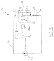
- a refrigeration system 10 comprises a compressor 12, a condenser 14, a fresh food evaporator 16 and a freezer evaporator 18 connected in series.
- the fresh food evaporator 16 is in a fresh food compartment 17, while the freezer evaporator 18 is in a freezer compartment 19.
- the system comprises a by-pass conduit 20 which by-passes the fresh food evaporator 16 and is controlled by a valve 22.
- such by-pass conduit is not present.
- the refrigeration system 20 is driven through a control process unit 24 linked to the compressor 12, to the valve 22 and to the electric motor 26a of a fan 26 blowing air over the fresh food evaporator 16.
- the fan 26 is switched on with the compressor 12 whenever a refrigerant flow is requested in the first evaporator 16, which in the examples shown in the drawings is the fresh food evaporator.
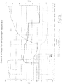
- the result is shown in figure 3 in which there is shown a ON cycle of the compressor 12 in which the refrigerant is not by-passed, i.e. it flows first in the fresh food evaporator 16 and then in the freezer evaporator 18.
- the switching on of the fan 26 contributes to a quite high rise of temperature of the freezer evaporator 18, which takes about 510 sec before reaching a value below -22°C.
Description
- The present invention relates to a refrigeration appliance including a refrigeration system comprising a first compartment including a first evaporator and a fan coupled to said first evaporator, a second compartment including a second evaporator connected in series and downstream said first evaporator, a compressor operationally coupled to said first evaporator and said second evaporator, and a control circuit for driving the compressor and the fan in order to switch on the compressor and the fan when there is a cooling demand in any of said compartments.
- In the above kind of two compartments refrigeration appliances (fresh food and freezer) said compartments are cooled by two evaporators located inside the two cavities. In the most common layout the two evaporators are connected in series, with or without a by-pass branch which connects the refrigeration system upstream the first evaporator with the system downstream such evaporator. The refrigerant expansion occurs in the first evaporator first, while the second evaporator is downstream. Temperature control of such appliances is usually performed by means of three temperature sensors located on the fresh food evaporator (it controls fresh food evaporator defrost), inside the fresh food (it controls fresh food compartment temperature) and on freezer evaporator (it controls freezer compartment temperature). Document
US-B-6 286 326 discloses a refrigeration appliance including a refrigeration system comprising a fresh food compartment having a fresh food evaporator and a fan coupled to said fresh food evaporator, a freezer compartment having a freezer evaporator connected in series and upstream the fresh food evaporator and a control circuit for driving the compressor and the fan in order to switch on the compressor and the fan when there is a cooling demand in any of said compartments. In the known solutions, when the compressor starts-up, the air circulating fan motor located inside the first compartment, for instance the fresh food compartment, starts as well. Having a forced air circulation inside the first compartment means increasing the heat exchange rate of first evaporator and reducing the temperature swing between different positions inside the first compartment. Therefore the fan improves the cooling efficiency and the food preservation inside first compartment. The drawback of the use of such a fan is related to the negative impact on the cooling efficiency of the second evaporator (downstream the first evaporator), during the transient period after compressor start-up. As a matter of fact, after compressor start-up, the first evaporator begins to cool down, but the high heat exchange rate due to the fan causes a rapid evaporation of the refrigerant. Warm gaseous refrigerant enters the second evaporator, causing a temporary temperature raise-up that has a negative impact on cooling efficiency. - It is an object of the present invention to provide a refrigeration appliance and a method for controlling such appliance which do not present the above mentioned drawbacks.
- According to the invention, such object is reached thanks to the features listed in the appended claims.
- The solution according to the present invention is used for refrigerators having the fresh food evaporator upstream the freezer evaporator, and its main feature is to delay the fan motor switch-on compared with the compressor start-up. The first evaporator has therefore a lower heat transfer rate (natural convection vs. forced-air convection) and cold liquid refrigerant enters the second evaporator earlier than with known present solutions. The main benefit of this solution is therefore to cool down more efficiently the second compartment, by avoiding the raise-up temperature that occurs at every compressor start-up. Moreover, fan delay means a lower energy consumption of the fan motor and a lower additional heat load into the first compartment due to the motor of the fan. The duration of the delay can be controlled in different ways. According to a first embodiment of the present invention, there can be a fixed time delay. According to a second embodiment, the delay ends when temperature difference between fresh food evaporator and freezer evaporator is smaller than a predetermined value. According to a third embodiment the delay ends when the temperature derivative of the freezer temperature curve is lower than a predetermined value, or comprised in a predetermined range of values, therefore indicating that evaporator temperature starts to be cool down.
- Further features and advantages of a refrigeration appliance and to a method according to the present invention will be clear from the following detailed description, with reference to the attached drawings in which:
-
figure 1 is a schematic view of the refrigeration system of an appliance according to the present invention; -
figure 2 is a diagram showing the behavior of a refrigeration system according to the prior art, in which the fan is in "ON" configuration on upstream evaporator; and -
figure 3 is a diagram similar tofigure 1 which refers to a refrigeration system of a refrigerator according to the invention, in which the fan is in "OFF" configuration on upstream evaporator. - With reference to the drawings, a
refrigeration system 10 comprises a compressor 12, a condenser 14, a fresh food evaporator 16 and a freezer evaporator 18 connected in series. The fresh food evaporator 16 is in afresh food compartment 17, while the freezer evaporator 18 is in a freezer compartment 19. According to an embodiment of the present invention, the system comprises a by-pass conduit 20 which by-passes the fresh food evaporator 16 and is controlled by avalve 22. According to another embodiment of the invention (not shown) such by-pass conduit is not present. - The
refrigeration system 20 is driven through a control process unit 24 linked to the compressor 12, to thevalve 22 and to the electric motor 26a of a fan 26 blowing air over the fresh food evaporator 16. - In the known solutions, the fan 26 is switched on with the compressor 12 whenever a refrigerant flow is requested in the first evaporator 16, which in the examples shown in the drawings is the fresh food evaporator. The result is shown in
figure 3 in which there is shown a ON cycle of the compressor 12 in which the refrigerant is not by-passed, i.e. it flows first in the fresh food evaporator 16 and then in the freezer evaporator 18. In this cycle, the switching on of the fan 26 contributes to a quite high rise of temperature of the freezer evaporator 18, which takes about 510 sec before reaching a value below -22°C. In the solution according to the present invention (figure 3 ), where the switching on of the fan 26 is delayed, the temperature of the freezer evaporator 18 takes only 210 sec before reaching a value below -22°C, all the other parameter being identical (i.e. identical refrigerator with identical refrigeration system). - This means a higher energy efficiency of a refrigeration appliance according to the invention. Even if in the above example only one fan is shown in the first compartment, a second fan can be used in the second compartment as well.
Claims (10)
- A refrigeration appliance including a refrigeration system (10) comprising:- a fresh food compartment (17) having a fresh food evaporator (16) and a fan (26, 26a) coupled to said fresh food evaporator (16),- a freezer compartment (19) having a freezer evaporator (18) connected in series and downstream the fresh food evaporator (16),- a compressor (12) operationally coupled to said fresh food evaporator (16) and said freezer evaporator (18), and- a control circuit (24) for driving the compressor (12) and the fan (26) in order to switch on the compressor and the fan when there is a cooling demand in any of said compartments, wherein the control circuit (24) is adapted to delay the switching-on of the fan (26, 26a) for a predetermined time after the compressor (12) is switched on.
- A refrigeration appliance according to claim 1, wherein said predetermined delay time is a fixed time.
- A refrigeration appliance according to claim 1, wherein said predetermined delay time is based on the time taken by the temperature difference between the fresh food evaporator (16) and the freezer evaporator (18) to be smaller than a predetermined value.
- A refrigeration appliance according to claim 1, wherein said predetermined delay time is based on the time taken by the temperature derivative of the freezer evaporator (18) to become lower than a predetermined value.
- A refrigeration appliance according to claim 1, wherein said predetermined delay time is based on the time taken by the temperature derivative of the freezer evaporator (18) to become comprised within a predetermined range of values.
- A method for controlling a refrigeration appliance including a refrigeration system (10) comprising a fresh food compartment (17) including a fresh food evaporator (16) and a fan (26, 26a) coupled to said fresh food evaporator (16), a freezer compartment (19) including a freezer evaporator (18) connected in series and downstream the fresh food evaporator (16), a compressor (12) operationally coupled to said fresh food evaporator (16) and said freezer evaporator (18), and a control circuit (24) for driving the compressor (12) and the fan (26) in order to switch on the compressor (12) and the fan (26) when there is a cooling demand in any of said compartments, characterized in that it comprises the step of delaying the switching-on of the fan (26, 26a) for a predetermined time after the compressor (12) is switched on.
- A method according to claim 6, wherein said predetermined delay time is a fixed time.
- A method according to claim 6, wherein said predetermined delay time is based on the time taken by the temperature difference between the fresh food evaporator (16) and the freezer evaporator (18) to be smaller than a predetermined value.
- A method according to claim 6, wherein said predetermined delay time is based on the time taken by the temperature derivative of the freezer evaporator (18) to become lower than a predetermined value.
- A method according to claim 6, wherein said predetermined delay time is based on the time taken by the temperature derivative of the freezer evaporator (18) to become within a predetermined range of values.
Priority Applications (3)
| Application Number | Priority Date | Filing Date | Title |
|---|---|---|---|
| EP10186438.7A EP2437008B1 (en) | 2010-10-04 | 2010-10-04 | Refrigeration appliance with two evaporators in series and method for controlling such appliance |
| CA2753781A CA2753781A1 (en) | 2010-10-04 | 2011-09-30 | Refrigeration appliance with two evaporators in series and method for controlling such appliance |
| BRPI1105270-8A BRPI1105270A2 (en) | 2010-10-04 | 2011-10-04 | refrigeration apparatus with two serial evaporators and method for controlling such apparatus |
Applications Claiming Priority (1)
| Application Number | Priority Date | Filing Date | Title |
|---|---|---|---|
| EP10186438.7A EP2437008B1 (en) | 2010-10-04 | 2010-10-04 | Refrigeration appliance with two evaporators in series and method for controlling such appliance |
Publications (2)
| Publication Number | Publication Date |
|---|---|
| EP2437008A1 EP2437008A1 (en) | 2012-04-04 |
| EP2437008B1 true EP2437008B1 (en) | 2018-07-04 |
Family
ID=43530713
Family Applications (1)
| Application Number | Title | Priority Date | Filing Date |
|---|---|---|---|
| EP10186438.7A Active EP2437008B1 (en) | 2010-10-04 | 2010-10-04 | Refrigeration appliance with two evaporators in series and method for controlling such appliance |
Country Status (3)
| Country | Link |
|---|---|
| EP (1) | EP2437008B1 (en) |
| BR (1) | BRPI1105270A2 (en) |
| CA (1) | CA2753781A1 (en) |
Families Citing this family (2)
| Publication number | Priority date | Publication date | Assignee | Title |
|---|---|---|---|---|
| GB2542604A (en) * | 2015-09-25 | 2017-03-29 | Linde Ag | Refrigeration apparatus |
| US10941981B2 (en) * | 2019-05-02 | 2021-03-09 | Haier Us Appliance Solutions, Inc. | Refrigeration appliances and methods of minimizing noise impact |
Citations (1)
| Publication number | Priority date | Publication date | Assignee | Title |
|---|---|---|---|---|
| WO2000071947A1 (en) * | 1999-05-26 | 2000-11-30 | Work Smart Energy Enterprises, Inc. | Improved control system for a refrigerator with two evaporating temperatures |
Family Cites Families (2)
| Publication number | Priority date | Publication date | Assignee | Title |
|---|---|---|---|---|
| KR20070054462A (en) * | 2005-11-23 | 2007-05-29 | 삼성전자주식회사 | Refrigerator and its control method |
| DE202007006632U1 (en) * | 2006-12-22 | 2008-04-30 | Liebherr-Hausgeräte Ochsenhausen GmbH | Fridge and / or freezer |
-
2010
- 2010-10-04 EP EP10186438.7A patent/EP2437008B1/en active Active
-
2011
- 2011-09-30 CA CA2753781A patent/CA2753781A1/en not_active Abandoned
- 2011-10-04 BR BRPI1105270-8A patent/BRPI1105270A2/en not_active IP Right Cessation
Patent Citations (1)
| Publication number | Priority date | Publication date | Assignee | Title |
|---|---|---|---|---|
| WO2000071947A1 (en) * | 1999-05-26 | 2000-11-30 | Work Smart Energy Enterprises, Inc. | Improved control system for a refrigerator with two evaporating temperatures |
Also Published As
| Publication number | Publication date |
|---|---|
| BRPI1105270A2 (en) | 2013-02-13 |
| EP2437008A1 (en) | 2012-04-04 |
| CA2753781A1 (en) | 2012-04-04 |
Similar Documents
| Publication | Publication Date | Title |
|---|---|---|
| US20150276306A1 (en) | Synchronous temperature rate control and apparatus for refrigeration with reduced energy consumption | |
| CN103335469B (en) | The control method of wind cooling refrigerator and wind cooling refrigerator | |
| JP6312300B2 (en) | Hot gas defrosting type refrigeration equipment and defrosting method | |
| RU2459159C2 (en) | Refrigerating machine and its operating procedure | |
| JP5641875B2 (en) | Refrigeration equipment | |
| CN103547872A (en) | Refrigerator | |
| US20150276289A1 (en) | Synchronous compartment temperature control and apparatus for refrigeration with reduced energy consumption | |
| CN110779260B (en) | Three-circulation quick-cooling frost-free refrigerator and continuous operation method thereof | |
| KR20140071411A (en) | Refrigerator and method of operating refrigeration system | |
| CN106568269B (en) | Refrigerator | |
| JP2011231956A (en) | Refrigerator-freezer | |
| CN102798245B (en) | Refrigerating equipment, refrigerating system and deep refrigerating method of refrigerating equipment | |
| WO2018076583A1 (en) | Refrigerator | |
| WO2010089191A3 (en) | Refrigeration device, in particular household refrigeration device, and method for controlling a refrigeration device | |
| EP2437008B1 (en) | Refrigeration appliance with two evaporators in series and method for controlling such appliance | |
| CN212362559U (en) | Diversified refrigeration equipment | |
| CN203396183U (en) | Refrigerating system and refrigerator with refrigerating system | |
| CN102116555A (en) | Refrigerator | |
| KR101708933B1 (en) | Refrigerant circulation system for Refrigerating apparatus | |
| JP2011144964A (en) | Refrigerator-freezer | |
| RU2011122271A (en) | REFRIGERATING UNIT WITH MULTIPLE STORAGE DIVISIONS | |
| CN109163489B (en) | Refrigeration method and device and horizontal air-cooled refrigeration cabinet with device | |
| KR101533644B1 (en) | Hotgas defrosting refrigerating cycle device | |
| KR20100124490A (en) | A refreeze dryer | |
| JP2005257164A (en) | Cooler |
Legal Events
| Date | Code | Title | Description |
|---|---|---|---|
| PUAI | Public reference made under article 153(3) epc to a published international application that has entered the european phase |
Free format text: ORIGINAL CODE: 0009012 |
|
| AK | Designated contracting states |
Kind code of ref document: A1 Designated state(s): AL AT BE BG CH CY CZ DE DK EE ES FI FR GB GR HR HU IE IS IT LI LT LU LV MC MK MT NL NO PL PT RO RS SE SI SK SM TR |
|
| AX | Request for extension of the european patent |
Extension state: BA ME |
|
| 17P | Request for examination filed |
Effective date: 20121001 |
|
| 17Q | First examination report despatched |
Effective date: 20160405 |
|
| GRAP | Despatch of communication of intention to grant a patent |
Free format text: ORIGINAL CODE: EPIDOSNIGR1 |
|
| STAA | Information on the status of an ep patent application or granted ep patent |
Free format text: STATUS: GRANT OF PATENT IS INTENDED |
|
| INTG | Intention to grant announced |
Effective date: 20180423 |
|
| GRAS | Grant fee paid |
Free format text: ORIGINAL CODE: EPIDOSNIGR3 |
|
| GRAA | (expected) grant |
Free format text: ORIGINAL CODE: 0009210 |
|
| STAA | Information on the status of an ep patent application or granted ep patent |
Free format text: STATUS: THE PATENT HAS BEEN GRANTED |
|
| AK | Designated contracting states |
Kind code of ref document: B1 Designated state(s): AL AT BE BG CH CY CZ DE DK EE ES FI FR GB GR HR HU IE IS IT LI LT LU LV MC MK MT NL NO PL PT RO RS SE SI SK SM TR |
|
| REG | Reference to a national code |
Ref country code: GB Ref legal event code: FG4D |
|
| REG | Reference to a national code |
Ref country code: CH Ref legal event code: EP |
|
| REG | Reference to a national code |
Ref country code: AT Ref legal event code: REF Ref document number: 1014947 Country of ref document: AT Kind code of ref document: T Effective date: 20180715 |
|
| REG | Reference to a national code |
Ref country code: IE Ref legal event code: FG4D |
|
| REG | Reference to a national code |
Ref country code: DE Ref legal event code: R096 Ref document number: 602010051614 Country of ref document: DE |
|
| REG | Reference to a national code |
Ref country code: FR Ref legal event code: PLFP Year of fee payment: 9 |
|
| REG | Reference to a national code |
Ref country code: NL Ref legal event code: MP Effective date: 20180704 |
|
| REG | Reference to a national code |
Ref country code: LT Ref legal event code: MG4D |
|
| REG | Reference to a national code |
Ref country code: AT Ref legal event code: MK05 Ref document number: 1014947 Country of ref document: AT Kind code of ref document: T Effective date: 20180704 |
|
| PG25 | Lapsed in a contracting state [announced via postgrant information from national office to epo] |
Ref country code: NL Free format text: LAPSE BECAUSE OF FAILURE TO SUBMIT A TRANSLATION OF THE DESCRIPTION OR TO PAY THE FEE WITHIN THE PRESCRIBED TIME-LIMIT Effective date: 20180704 |
|
| PG25 | Lapsed in a contracting state [announced via postgrant information from national office to epo] |
Ref country code: CZ Free format text: LAPSE BECAUSE OF FAILURE TO SUBMIT A TRANSLATION OF THE DESCRIPTION OR TO PAY THE FEE WITHIN THE PRESCRIBED TIME-LIMIT Effective date: 20180704 Ref country code: PL Free format text: LAPSE BECAUSE OF FAILURE TO SUBMIT A TRANSLATION OF THE DESCRIPTION OR TO PAY THE FEE WITHIN THE PRESCRIBED TIME-LIMIT Effective date: 20180704 Ref country code: LT Free format text: LAPSE BECAUSE OF FAILURE TO SUBMIT A TRANSLATION OF THE DESCRIPTION OR TO PAY THE FEE WITHIN THE PRESCRIBED TIME-LIMIT Effective date: 20180704 Ref country code: RS Free format text: LAPSE BECAUSE OF FAILURE TO SUBMIT A TRANSLATION OF THE DESCRIPTION OR TO PAY THE FEE WITHIN THE PRESCRIBED TIME-LIMIT Effective date: 20180704 Ref country code: SE Free format text: LAPSE BECAUSE OF FAILURE TO SUBMIT A TRANSLATION OF THE DESCRIPTION OR TO PAY THE FEE WITHIN THE PRESCRIBED TIME-LIMIT Effective date: 20180704 Ref country code: BG Free format text: LAPSE BECAUSE OF FAILURE TO SUBMIT A TRANSLATION OF THE DESCRIPTION OR TO PAY THE FEE WITHIN THE PRESCRIBED TIME-LIMIT Effective date: 20181004 Ref country code: FI Free format text: LAPSE BECAUSE OF FAILURE TO SUBMIT A TRANSLATION OF THE DESCRIPTION OR TO PAY THE FEE WITHIN THE PRESCRIBED TIME-LIMIT Effective date: 20180704 Ref country code: NO Free format text: LAPSE BECAUSE OF FAILURE TO SUBMIT A TRANSLATION OF THE DESCRIPTION OR TO PAY THE FEE WITHIN THE PRESCRIBED TIME-LIMIT Effective date: 20181004 Ref country code: GR Free format text: LAPSE BECAUSE OF FAILURE TO SUBMIT A TRANSLATION OF THE DESCRIPTION OR TO PAY THE FEE WITHIN THE PRESCRIBED TIME-LIMIT Effective date: 20181005 Ref country code: AT Free format text: LAPSE BECAUSE OF FAILURE TO SUBMIT A TRANSLATION OF THE DESCRIPTION OR TO PAY THE FEE WITHIN THE PRESCRIBED TIME-LIMIT Effective date: 20180704 Ref country code: IS Free format text: LAPSE BECAUSE OF FAILURE TO SUBMIT A TRANSLATION OF THE DESCRIPTION OR TO PAY THE FEE WITHIN THE PRESCRIBED TIME-LIMIT Effective date: 20181104 |
|
| PG25 | Lapsed in a contracting state [announced via postgrant information from national office to epo] |
Ref country code: ES Free format text: LAPSE BECAUSE OF FAILURE TO SUBMIT A TRANSLATION OF THE DESCRIPTION OR TO PAY THE FEE WITHIN THE PRESCRIBED TIME-LIMIT Effective date: 20180704 Ref country code: HR Free format text: LAPSE BECAUSE OF FAILURE TO SUBMIT A TRANSLATION OF THE DESCRIPTION OR TO PAY THE FEE WITHIN THE PRESCRIBED TIME-LIMIT Effective date: 20180704 Ref country code: LV Free format text: LAPSE BECAUSE OF FAILURE TO SUBMIT A TRANSLATION OF THE DESCRIPTION OR TO PAY THE FEE WITHIN THE PRESCRIBED TIME-LIMIT Effective date: 20180704 Ref country code: AL Free format text: LAPSE BECAUSE OF FAILURE TO SUBMIT A TRANSLATION OF THE DESCRIPTION OR TO PAY THE FEE WITHIN THE PRESCRIBED TIME-LIMIT Effective date: 20180704 |
|
| REG | Reference to a national code |
Ref country code: DE Ref legal event code: R097 Ref document number: 602010051614 Country of ref document: DE |
|
| PG25 | Lapsed in a contracting state [announced via postgrant information from national office to epo] |
Ref country code: EE Free format text: LAPSE BECAUSE OF FAILURE TO SUBMIT A TRANSLATION OF THE DESCRIPTION OR TO PAY THE FEE WITHIN THE PRESCRIBED TIME-LIMIT Effective date: 20180704 Ref country code: RO Free format text: LAPSE BECAUSE OF FAILURE TO SUBMIT A TRANSLATION OF THE DESCRIPTION OR TO PAY THE FEE WITHIN THE PRESCRIBED TIME-LIMIT Effective date: 20180704 |
|
| PLBE | No opposition filed within time limit |
Free format text: ORIGINAL CODE: 0009261 |
|
| STAA | Information on the status of an ep patent application or granted ep patent |
Free format text: STATUS: NO OPPOSITION FILED WITHIN TIME LIMIT |
|
| PG25 | Lapsed in a contracting state [announced via postgrant information from national office to epo] |
Ref country code: SM Free format text: LAPSE BECAUSE OF FAILURE TO SUBMIT A TRANSLATION OF THE DESCRIPTION OR TO PAY THE FEE WITHIN THE PRESCRIBED TIME-LIMIT Effective date: 20180704 Ref country code: SK Free format text: LAPSE BECAUSE OF FAILURE TO SUBMIT A TRANSLATION OF THE DESCRIPTION OR TO PAY THE FEE WITHIN THE PRESCRIBED TIME-LIMIT Effective date: 20180704 Ref country code: DK Free format text: LAPSE BECAUSE OF FAILURE TO SUBMIT A TRANSLATION OF THE DESCRIPTION OR TO PAY THE FEE WITHIN THE PRESCRIBED TIME-LIMIT Effective date: 20180704 |
|
| REG | Reference to a national code |
Ref country code: CH Ref legal event code: PL |
|
| 26N | No opposition filed |
Effective date: 20190405 |
|
| REG | Reference to a national code |
Ref country code: BE Ref legal event code: MM Effective date: 20181031 |
|
| PG25 | Lapsed in a contracting state [announced via postgrant information from national office to epo] |
Ref country code: LU Free format text: LAPSE BECAUSE OF NON-PAYMENT OF DUE FEES Effective date: 20181004 Ref country code: MC Free format text: LAPSE BECAUSE OF FAILURE TO SUBMIT A TRANSLATION OF THE DESCRIPTION OR TO PAY THE FEE WITHIN THE PRESCRIBED TIME-LIMIT Effective date: 20180704 |
|
| REG | Reference to a national code |
Ref country code: IE Ref legal event code: MM4A |
|
| PG25 | Lapsed in a contracting state [announced via postgrant information from national office to epo] |
Ref country code: CH Free format text: LAPSE BECAUSE OF NON-PAYMENT OF DUE FEES Effective date: 20181031 Ref country code: SI Free format text: LAPSE BECAUSE OF FAILURE TO SUBMIT A TRANSLATION OF THE DESCRIPTION OR TO PAY THE FEE WITHIN THE PRESCRIBED TIME-LIMIT Effective date: 20180704 Ref country code: LI Free format text: LAPSE BECAUSE OF NON-PAYMENT OF DUE FEES Effective date: 20181031 Ref country code: BE Free format text: LAPSE BECAUSE OF NON-PAYMENT OF DUE FEES Effective date: 20181031 |
|
| PG25 | Lapsed in a contracting state [announced via postgrant information from national office to epo] |
Ref country code: IE Free format text: LAPSE BECAUSE OF NON-PAYMENT OF DUE FEES Effective date: 20181004 |
|
| PG25 | Lapsed in a contracting state [announced via postgrant information from national office to epo] |
Ref country code: MT Free format text: LAPSE BECAUSE OF NON-PAYMENT OF DUE FEES Effective date: 20181004 |
|
| PG25 | Lapsed in a contracting state [announced via postgrant information from national office to epo] |
Ref country code: TR Free format text: LAPSE BECAUSE OF FAILURE TO SUBMIT A TRANSLATION OF THE DESCRIPTION OR TO PAY THE FEE WITHIN THE PRESCRIBED TIME-LIMIT Effective date: 20180704 |
|
| PG25 | Lapsed in a contracting state [announced via postgrant information from national office to epo] |
Ref country code: PT Free format text: LAPSE BECAUSE OF FAILURE TO SUBMIT A TRANSLATION OF THE DESCRIPTION OR TO PAY THE FEE WITHIN THE PRESCRIBED TIME-LIMIT Effective date: 20180704 |
|
| PG25 | Lapsed in a contracting state [announced via postgrant information from national office to epo] |
Ref country code: MK Free format text: LAPSE BECAUSE OF NON-PAYMENT OF DUE FEES Effective date: 20180704 Ref country code: HU Free format text: LAPSE BECAUSE OF FAILURE TO SUBMIT A TRANSLATION OF THE DESCRIPTION OR TO PAY THE FEE WITHIN THE PRESCRIBED TIME-LIMIT; INVALID AB INITIO Effective date: 20101004 Ref country code: CY Free format text: LAPSE BECAUSE OF FAILURE TO SUBMIT A TRANSLATION OF THE DESCRIPTION OR TO PAY THE FEE WITHIN THE PRESCRIBED TIME-LIMIT Effective date: 20180704 |
|
| PGFP | Annual fee paid to national office [announced via postgrant information from national office to epo] |
Ref country code: IT Payment date: 20210910 Year of fee payment: 12 Ref country code: FR Payment date: 20210917 Year of fee payment: 12 |
|
| PGFP | Annual fee paid to national office [announced via postgrant information from national office to epo] |
Ref country code: GB Payment date: 20210901 Year of fee payment: 12 |
|
| GBPC | Gb: european patent ceased through non-payment of renewal fee |
Effective date: 20221004 |
|
| P01 | Opt-out of the competence of the unified patent court (upc) registered |
Effective date: 20230522 |
|
| PG25 | Lapsed in a contracting state [announced via postgrant information from national office to epo] |
Ref country code: FR Free format text: LAPSE BECAUSE OF NON-PAYMENT OF DUE FEES Effective date: 20221031 |
|
| PG25 | Lapsed in a contracting state [announced via postgrant information from national office to epo] |
Ref country code: IT Free format text: LAPSE BECAUSE OF NON-PAYMENT OF DUE FEES Effective date: 20221004 Ref country code: GB Free format text: LAPSE BECAUSE OF NON-PAYMENT OF DUE FEES Effective date: 20221004 |
|
| PGFP | Annual fee paid to national office [announced via postgrant information from national office to epo] |
Ref country code: DE Payment date: 20231027 Year of fee payment: 14 |