EP3147505A1 - Multi-stage compression system, control device, control method, and program - Google Patents
Multi-stage compression system, control device, control method, and program Download PDFInfo
- Publication number
- EP3147505A1 EP3147505A1 EP15814779.3A EP15814779A EP3147505A1 EP 3147505 A1 EP3147505 A1 EP 3147505A1 EP 15814779 A EP15814779 A EP 15814779A EP 3147505 A1 EP3147505 A1 EP 3147505A1
- Authority
- EP
- European Patent Office
- Prior art keywords
- open
- malfunction
- stage
- compressors
- opening
- Prior art date
- Legal status (The legal status is an assumption and is not a legal conclusion. Google has not performed a legal analysis and makes no representation as to the accuracy of the status listed.)
- Withdrawn
Links
- 230000006835 compression Effects 0.000 title claims abstract description 61
- 238000007906 compression Methods 0.000 title claims abstract description 61
- 238000000034 method Methods 0.000 title claims description 25
- 230000007257 malfunction Effects 0.000 claims abstract description 132
- 239000007789 gas Substances 0.000 claims abstract description 93
- 230000035945 sensitivity Effects 0.000 claims description 10
- 230000006870 function Effects 0.000 description 56
- 238000010586 diagram Methods 0.000 description 8
- 230000002159 abnormal effect Effects 0.000 description 7
- 238000005516 engineering process Methods 0.000 description 4
- 238000011143 downstream manufacturing Methods 0.000 description 3
- 238000011144 upstream manufacturing Methods 0.000 description 3
- IJGRMHOSHXDMSA-UHFFFAOYSA-N Atomic nitrogen Chemical compound N#N IJGRMHOSHXDMSA-UHFFFAOYSA-N 0.000 description 2
- 238000004891 communication Methods 0.000 description 1
- 238000004590 computer program Methods 0.000 description 1
- 230000000694 effects Effects 0.000 description 1
- 230000007274 generation of a signal involved in cell-cell signaling Effects 0.000 description 1
- 230000010354 integration Effects 0.000 description 1
- 229910052757 nitrogen Inorganic materials 0.000 description 1
- 239000004065 semiconductor Substances 0.000 description 1
Images


Classifications
-
- F—MECHANICAL ENGINEERING; LIGHTING; HEATING; WEAPONS; BLASTING
- F04—POSITIVE - DISPLACEMENT MACHINES FOR LIQUIDS; PUMPS FOR LIQUIDS OR ELASTIC FLUIDS
- F04D—NON-POSITIVE-DISPLACEMENT PUMPS
- F04D27/00—Control, e.g. regulation, of pumps, pumping installations or pumping systems specially adapted for elastic fluids
- F04D27/02—Surge control
- F04D27/0246—Surge control by varying geometry within the pumps, e.g. by adjusting vanes
-
- F—MECHANICAL ENGINEERING; LIGHTING; HEATING; WEAPONS; BLASTING
- F04—POSITIVE - DISPLACEMENT MACHINES FOR LIQUIDS; PUMPS FOR LIQUIDS OR ELASTIC FLUIDS
- F04D—NON-POSITIVE-DISPLACEMENT PUMPS
- F04D27/00—Control, e.g. regulation, of pumps, pumping installations or pumping systems specially adapted for elastic fluids
- F04D27/001—Testing thereof; Determination or simulation of flow characteristics; Stall or surge detection, e.g. condition monitoring
-
- F—MECHANICAL ENGINEERING; LIGHTING; HEATING; WEAPONS; BLASTING
- F04—POSITIVE - DISPLACEMENT MACHINES FOR LIQUIDS; PUMPS FOR LIQUIDS OR ELASTIC FLUIDS
- F04D—NON-POSITIVE-DISPLACEMENT PUMPS
- F04D17/00—Radial-flow pumps, e.g. centrifugal pumps; Helico-centrifugal pumps
- F04D17/08—Centrifugal pumps
- F04D17/10—Centrifugal pumps for compressing or evacuating
- F04D17/12—Multi-stage pumps
-
- F—MECHANICAL ENGINEERING; LIGHTING; HEATING; WEAPONS; BLASTING
- F04—POSITIVE - DISPLACEMENT MACHINES FOR LIQUIDS; PUMPS FOR LIQUIDS OR ELASTIC FLUIDS
- F04D—NON-POSITIVE-DISPLACEMENT PUMPS
- F04D27/00—Control, e.g. regulation, of pumps, pumping installations or pumping systems specially adapted for elastic fluids
- F04D27/009—Control, e.g. regulation, of pumps, pumping installations or pumping systems specially adapted for elastic fluids by bleeding, by passing or recycling fluid
-
- F—MECHANICAL ENGINEERING; LIGHTING; HEATING; WEAPONS; BLASTING
- F04—POSITIVE - DISPLACEMENT MACHINES FOR LIQUIDS; PUMPS FOR LIQUIDS OR ELASTIC FLUIDS
- F04D—NON-POSITIVE-DISPLACEMENT PUMPS
- F04D27/00—Control, e.g. regulation, of pumps, pumping installations or pumping systems specially adapted for elastic fluids
- F04D27/02—Surge control
- F04D27/0292—Stop safety or alarm devices, e.g. stop-and-go control; Disposition of check-valves
-
- F—MECHANICAL ENGINEERING; LIGHTING; HEATING; WEAPONS; BLASTING
- F04—POSITIVE - DISPLACEMENT MACHINES FOR LIQUIDS; PUMPS FOR LIQUIDS OR ELASTIC FLUIDS
- F04D—NON-POSITIVE-DISPLACEMENT PUMPS
- F04D29/00—Details, component parts, or accessories
- F04D29/40—Casings; Connections of working fluid
- F04D29/42—Casings; Connections of working fluid for radial or helico-centrifugal pumps
- F04D29/44—Fluid-guiding means, e.g. diffusers
- F04D29/46—Fluid-guiding means, e.g. diffusers adjustable
- F04D29/462—Fluid-guiding means, e.g. diffusers adjustable especially adapted for elastic fluid pumps
-
- F—MECHANICAL ENGINEERING; LIGHTING; HEATING; WEAPONS; BLASTING
- F05—INDEXING SCHEMES RELATING TO ENGINES OR PUMPS IN VARIOUS SUBCLASSES OF CLASSES F01-F04
- F05B—INDEXING SCHEME RELATING TO WIND, SPRING, WEIGHT, INERTIA OR LIKE MOTORS, TO MACHINES OR ENGINES FOR LIQUIDS COVERED BY SUBCLASSES F03B, F03D AND F03G
- F05B2270/00—Control
- F05B2270/10—Purpose of the control system
- F05B2270/109—Purpose of the control system to prolong engine life
- F05B2270/1095—Purpose of the control system to prolong engine life by limiting mechanical stresses
Definitions
- the present invention relates to a multi-stage compression system, a control device, a control method, and a program.
- a compressor which compresses gases and supplies the compressed gases to machines or the like connected downstream is known.
- this compressor there is a compressor in which a gas flow rate for a compressor body is adjusted by arranging an inlet guide vane (IGV) upstream and adjusting a degree of opening of the IGV.
- IGV inlet guide vane
- Patent Document 1 technology of appropriately controlling a degree of opening of the IGV and performing an optimum operation even when a performance difference occurs among a plurality of compressor bodies is disclosed as related technology.
- Patent Document 1 Japanese Unexamined Patent Application, First Publication No. 2013-170573
- the present invention provides a multi-stage compression system, a control device, a control method, and a program capable of solving the above-described problem.
- a multi-stage compression system compresses gases compressed by a pair of first-stage compressors by subsequent compressors connected to the first-stage compressors in series.
- the multi-stage compression system includes: a valve control unit configured to output open/close signals for opening/closing valves for adjusting flow rates of gases flowing into the first-stage compressors provided at inlet sides of the first-stage compressors, wherein the valve control unit outputs the open/close signal having a difference less than or equal to a predetermined value with respect to a degree of opening of the valve before malfunction determination as the open/close signal until a malfunction is eliminated after the determination of the malfunction in which one of the valves does not have a degree of opening according to the open/close signal.
- a multi-stage compression system is a multi-stage compression system in which gases compressed by a pair of first-stage compressors are compressed by subsequent compressors connected to the first-stage compressors in series, the multi-stage compression system including: a valve control unit configured to output open/close signals for opening/closing valves for adjusting flow rates of gases flowing into the first-stage compressors provided at inlet sides of the first-stage compressors, wherein the valve control unit stores the open/close signal during malfunction determination and supplies the stored open/close signal until a malfunction is eliminated.
- the valve control unit stores an open/close signal during malfunction determination and limits the open/close signal of up to a necessary degree of opening to a predetermined change rate or less until the malfunction is eliminated.
- a multi-stage compression system is a multi-stage compression system in which gases compressed by a pair of first-stage compressors are compressed by subsequent compressors connected to the first-stage compressors in series, the multi-stage compression system including: a valve control unit configured to output open/close signals for opening/closing valves for adjusting flow rates of gases flowing into the first-stage compressors provided at inlet sides of the first-stage compressors, wherein the valve control unit outputs the open/close signal indicating a value of a degree of valve opening in normal times already determined during malfunction determination while maintaining the value after the malfunction determination when the open/close signal is output after the malfunction determination or outputs the open/close signal indicating a value of a degree of opening according to a newly measured opening degree determination signal after the malfunction determination.
- the valve control unit increases control sensitivity of another valve in which no malfunction is determined until the malfunction is eliminated after the malfunction is determined.
- a control device is a control device of a multi-stage compressor in which gases compressed by a pair of first-stage compressors are compressed by subsequent compressors connected to the first-stage compressors in series, the control device including: a valve control unit configured to output open/close signals for opening/closing valves for adjusting flow rates of gases flowing into the first-stage compressors provided at inlet sides of the first-stage compressors, wherein the valve control unit outputs the open/close signal having a difference less than or equal to a predetermined value with respect to a degree of opening of the valve before malfunction determination as the open/close signal until a malfunction is eliminated after the determination of the malfunction in which one of the valves does not have a degree of opening according to the open/close signal.
- a control device is a control device of a multi-stage compressor in which gases compressed by a pair of first-stage compressors are compressed by subsequent compressors connected to the first-stage compressors in series, the control device including: a valve control unit configured to output open/close signals for opening/closing valves for adjusting flow rates of gases flowing into the first-stage compressors provided at inlet sides of the first-stage compressors, wherein the valve control unit stores the open/close signal during malfunction determination and supplies the stored open/close signal until a malfunction is eliminated.
- the valve control unit stores an open/close signal during malfunction determination and limits the open/close signal of up to a necessary degree of opening to a predetermined change rate or less until the malfunction is eliminated.
- a control device is a control device of a multi-stage compressor in which gases compressed by a pair of first-stage compressors are compressed by subsequent compressors connected to the first-stage compressors in series, the control device including: a valve control unit configured to output open/close signals for opening/closing valves for adjusting flow rates of gases flowing into the first-stage compressors provided at inlet sides of the first-stage compressors, wherein the valve control unit outputs the open/close signal indicating a value of a degree of valve opening in normal times already determined during malfunction determination while maintaining the value after the malfunction determination when the open/close signal is output after the malfunction determination or outputs the open/close signal indicating a value of a degree of opening according to a newly measured opening degree determination signal after the malfunction determination.
- the valve control unit increases control sensitivity of another valve in which no malfunction is determined until the malfunction is eliminated after the malfunction is determined.
- a control method is a control method for use in a multi-stage compression system in which gases compressed by a pair of first-stage compressors are compressed by subsequent compressors connected to the first-stage compressors in series, the control method comprising: outputting, by a valve control unit, an open/close signal having a difference less than or equal to a predetermined value with respect to a degree of opening of a valve before malfunction determination as the open/close signal until a malfunction is eliminated after the determination of the malfunction in which one of the valves does not have a degree of opening according to the open/close signal compressors, wherein the valve control unit is configured to output open/close signals for opening/closing valves for adjusting flow rates of gases flowing into the first-stage compressors provided at inlet sides of the first-stage.
- a control method is a control method for use in a multi-stage compression system in which gases compressed by a pair of first-stage compressors are compressed by subsequent compressors connected to the first-stage compressors in series, the control method comprising: storing, by a valve control unit, an open/close signal during malfunction determination and supplies the stored open/close signal until a malfunction is eliminated, wherein the valve control unit is configured to output open/close signals for opening/closing valves for adjusting flow rates of gases flowing into the first-stage compressors provided at inlet sides of the first-stage compressors.
- the valve control unit stores an open/close signal during malfunction determination and limits the open/close signal of up to a necessary degree of opening to a predetermined change rate or less until the malfunction is eliminated.
- a control method for use in a multi-stage compression system in which gases compressed by a pair of first-stage compressors are compressed by subsequent compressors connected to the first-stage compressors in series comprising: outputting, by a valve control unit, an open/close signal indicating a value of a degree of valve opening in normal times already determined during malfunction determination while maintaining the value after the malfunction determination when the open/close signal is output after the malfunction determination or outputs the open/close signal indicating a value of a degree of opening according to a newly measured opening degree determination signal after the malfunction determination, wherein the valve control unit is configured to output open/close signals for opening/closing valves for adjusting flow rates of gases flowing into the first-stage compressors provided at inlet sides of the first-stage compressors.
- the valve control unit increases control sensitivity of another valve in which no malfunction is determined until the malfunction is eliminated after the malfunction is determined.
- a program is a program configured to cause a computer of a control device of a multi-stage compressor in which gases compressed by a pair of first-stage compressors are compressed by subsequent compressors connected to the first-stage compressors in series to function as: a valve control device configured to output open/close signals for opening/closing valves for adjusting flow rates of gases flowing into the first-stage compressors provided at inlet sides of the first-stage compressors, wherein the program causes the valve control device to output the open/close signal having a difference less than or equal to a predetermined value with respect to a degree of opening of a valve before malfunction determination as the open/close signal until a malfunction is eliminated after the determination of the malfunction in which one of the valves does not have a degree of opening according to the open/close signal.
- a program is a program configured to cause a computer of a control device of a multi-stage compressor in which gases compressed by a pair of first-stage compressors are compressed by subsequent compressors connected to the first-stage compressors in series to function as: a valve control device configured to output open/close signals for opening/closing valves for adjusting flow rates of gases flowing into the first-stage compressors provided at inlet sides of the first-stage compressors, wherein the program causes the valve control device to store the open/close signal during malfunction determination and supply the stored open/close signal until a malfunction is eliminated.
- the program causes the valve control device to store an open/close signal during malfunction determination and limit the open/close signal of up to a necessary degree of opening to a predetermined change rate or less until the malfunction is eliminated.
- a program is a program configured to cause a computer of a control device of a multi-stage compressor in which gases compressed by a pair of first-stage compressors are compressed by subsequent compressors connected to the first-stage compressors in series to function as: a valve control device configured to output open/close signals for opening/closing valves for adjusting flow rates of gases flowing into the first-stage compressors provided at inlet sides of the first-stage compressors, wherein the program causes the valve control device to output the open/close signal indicating a value of a degree of valve opening in normal times already determined during malfunction determination while maintaining the value after the malfunction determination when the open/close signal is output after the malfunction determination or output the open/close signal indicating a value of a degree of opening according to a newly measured opening degree determination signal after the malfunction determination.
- the program causes the valve control device to increase control sensitivity of another valve in which no malfunction is determined until the malfunction is eliminated after the malfunction is determined.
- the control device According to the multi-stage compression system, the control device, the control method, and the program described above, it is possible to improve controllability without making the overall plant unstable even when an alarm is generated in an abnormal state in a multi-stage compressor.
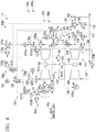
- Fig. 1 is a diagram showing an example of a configuration of a multi-stage compression system 1a according to the first embodiment of the present invention.
- a multi-stage compression system 1a includes a multi-stage compressor 10a and a compressor control device 200a (a control device).
- the multi-stage compressor 10a includes first-stage compressor bodies 101 (101a and 101b) arranged in series from an upstream side of a flow of a gas to a downstream side, a second-stage compressor body 103 (a subsequent-stage compressor), and a last-stage compressor body 102 (a subsequent-stage compressor).
- the first-stage compressor body 101 is formed of a pair including the first-stage compressor body 101a and the first-stage compressor body 101b.
- the first-stage compressor bodies 101 (101a and 101b), the second-stage compressor body 103, and the last-stage compressor body 102 are coupled via a shaft 106.
- the first-stage compressor bodies 101a and 101b are arranged to form a pair in parallel on the upstream side of the shaft 106.
- a motor 104 is connected to a middle portion of the shaft 106.
- Each compressor body and the motor 104 are connected to the shaft 106 via a gearbox 105.
- Supply lines 130a and 130b are pipes for supplying gases to the first-stage compressor bodies 101a and 101b.
- the supply line 130a is connected to an inlet of the first-stage compressor body 101a.
- the supply line 130b is connected to an inlet of the first-stage compressor body 101b.
- the first-stage compressor body 101a generates a compressed gas by taking in the gas via the supply line 130a and compressing the gas.
- the first-stage compressor body 101b generates a compressed gas by taking in the gas via the supply line 130b and compressing the gas.
- a first connection line 132 is a pipe for supplying the compressed gas generated by the first-stage compressor bodies 101a and 101b to the second-stage compressor body 103.
- the first connection line 132 is connected to an outlet of the first-stage compressor body 101a and an outlet of the first-stage compressor body 101b. Also, the first connection line 132 is connected to an inlet of the second-stage compressor body 103.
- the first connection line 132 includes a merging portion and the compressed gases discharged by the two first-stage compressor bodies 101a and 101b are merged in the merging portion. The first connection line 132 supplies the merged compressed gases to the second-stage compressor body 103.
- the second-stage compressor body 103 generates a compressed gas by further compressing the compressed gas taken in via the first connection line 132.
- a second connection line 133 is a pipe for supplying the compressed gas generated by the second-stage compressor body 103 to the last-stage compressor body 102.
- the second connection line 133 is connected to an outlet of the second-stage compressor body 103 and an inlet of the last-stage compressor body 102.
- the second connection line 133 supplies the compressed gas to the last-stage compressor body 102.
- the last-stage compressor body 102 generates a compressed gas by further compressing the compressed gas taken in via the second connection line 133.
- a discharge line 131 is a pipe for supplying the compressed gas generated by the last-stage compressor body 102 to a downstream process.
- the discharge line 131 is connected to an outlet of the last-stage compressor body 102 and an inlet of the downstream process.
- the discharge line 131 supplies the compressed gas to the downstream process.
- An inlet guide vane (hereinafter, IGV) 107a is provided in the supply line 130a around the inlet of the first-stage compressor body 101a.
- An IGV 107b is provided in the supply line 130b around the inlet of the first-stage compressor body 101b.
- the IGV 107a provided in the supply line 130a controls a flow rate of the gas flowing into the first-stage compressor body 101a.
- the IGV 107b provided in the supply line 130b controls a flow rate of the gas flowing into the first-stage compressor body 101b.
- the discharge line 131 around an outlet of the last-stage compressor body 102 is provided with a blowoff valve 108.
- the blowoff valve 108 When the compressor is a compressor in which the gas to be compressed is air, the blowoff valve 108 provided in the discharge line 131 discharges air into the atmosphere via a blowoff line 136.
- a recycle valve can be used.
- the blowoff valve 108 can return the gas to the supply line 130a via a recycle line by which the blowoff line 136 is connected to the supply line 130a.
- the blowoff valve 108 can return the gas to the supply line 130b via the recycle line connected to the supply line 130b via the blowoff line 136.
- the degrees of opening of IGV 107a, the IGV 107b, and the blowoff valve 108 are controlled for the purpose of controlling an outlet pressure of the multi-stage compressor 10a or preventing surging.
- An inlet flow rate determination unit 114a is arranged at the supply line 130a.
- the inlet flow rate determination unit 114a determines an inlet gas flow rate of a gas flowing into the first-stage compressor body 101a and generates an inlet flow rate determination value.
- An inlet flow rate determination unit 114b is arranged at the supply line 130b.
- the inlet flow rate determination unit 114b determines an inlet gas flow rate of a gas flowing into the first-stage compressor body 101b and generates an inlet flow rate determination value.
- a post-merger pressure determination unit 110 is arranged in the downstream side of the merging portion of the first connection line 132.
- the post-merger pressure determination unit 110 generates a post-merger pressure determination value by determining a pressure after the merging of the gases flowing out of the first-stage compressor bodies 101a and 101b.
- a cooler 109a is arranged at the first connection line 132. The cooler 109a cools the gas flowing inside the first connection line 132.
- a cooler 109b is arranged at the second connection line 133.
- the cooler 109b cools the gas flowing inside the second connection line 133.
- An outlet pressure determination unit 111 is arranged at the discharge line 131.
- the outlet pressure determination unit 111 generates an outlet pressure determination value by determining a pressure of the gas flowing out of the last-stage compressor body 102.
- an outlet flow rate determination unit 115 is arranged at the discharge line 131.
- the outlet flow rate determination unit 115 generates an outlet flow rate determination value by determining the flow rate of the gas flowing out of the last-stage compressor body 102.
- Fig. 2 is a diagram showing an example of the configuration of the compressor control device 200a in the first embodiment of the present invention.
- the compressor control device 200a in the first embodiment of the present invention is a configuration in which a valve control unit 30a is added to the compressor control device shown in Fig. 9 of Patent Document 1.
- the compressor control device 200a in the first embodiment includes a valve control unit 30a, IGV opening degree control units 50 (50a and 50b), and a blowoff valve opening degree control unit 53.
- the IGV opening degree control unit 50a controls a degree of opening of the IGV 107a.
- the IGV opening degree control unit 50b controls a degree of opening of the IGV 107b. Configurations of the IGV opening degree control unit 50a and the IGV opening degree control unit 50b are identical.
- the IGV opening degree control unit 50a includes an IGV opening degree command value generation unit 51 and an IGV opening degree command value correction unit 52a.
- the IGV opening degree control unit 50b includes the IGV opening degree command value generation unit 51 and an IGV opening degree command value correction unit 52b.
- the IGV opening degree command value generation unit 51 is common between the IGV opening degree control unit 50a and the IGV opening degree control unit 50b.
- the IGV opening degree command value generation unit 51 generates and outputs an IGV opening degree command value indicating a degree of opening of the IGV 107a.
- the IGV opening degree command value generation unit 51 generates and outputs an IGV opening degree command value indicating a degree of opening of the IGV 107b.
- the IGV opening degree command value generation unit 51 includes a pressure controller 129 and a function generator 116.
- the IGV opening degree command value correction units 52a and 52b correct an IGV opening degree command value output by the IGV opening degree command value generation unit 51.
- the IGV opening degree command value correction unit 52a includes a flow rate indicator 125 a which outputs an input inlet flow rate determination value as it is, a pressure indicator 126 which outputs an input post-merger pressure determination value as it is, and a function generator 117a which outputs an IGV opening degree correction value.
- the IGV opening degree command value correction unit 52b includes a flow rate indicator 125b which outputs an input inlet flow rate determination value as it is, the pressure indicator 126 which outputs an input post-merger pressure determination value as it is, and a function generator 117b which outputs an IGV opening degree correction value.
- the pressure indicator 126 is common between the IGV opening degree command value correction units 52a and 52b, but the present invention is not limited thereto.
- the blowoff valve opening degree control unit 53 controls a degree of opening of the blowoff valve 108.
- the blowoff valve opening degree control unit 53 includes upstream-side anti-surge control units 54 (54a and 54b), an outlet pressure control unit 55, a downstream-side anti-surge control unit 56, and a command value selection unit 112.
- anti-surge control is control for maintaining a flow rate at a fixed value or more in order to prevent the multi-stage compressor 10a from being damaged by so-called surging caused by a decrease in a flow rate in the compressor.
- the upstream-side anti-surge control unit 54a controls a degree of opening of the blowoff valve 108 in order to prevent surging from occurring in the first-stage compressor body 101a.
- the upstream-side anti-surge control unit 54b controls a degree of opening of the blowoff valve 108 in order to prevent surging from occurring in the first-stage compressor body 101b.
- configurations of the upstream-side anti-surge control unit 54a and the upstream-side anti-surge control unit 54b are identical.
- the upstream-side anti-surge control unit 54a includes a pressure indicator 126 which outputs an input post-merger outlet pressure determination value as it is, a function generator 118a which outputs an inlet flow rate target value, a flow rate indicator 125a which outputs an input inlet flow rate determination value as it is, and a flow rate controller 127a which outputs a blowoff valve opening degree command value on the basis of an inlet flow rate target value.
- the upstream-side anti-surge control unit 54b includes the pressure indicator 126 which outputs an input post-merger outlet pressure determination value as it is, a function generator 118b which outputs an inlet flow rate target value, a flow rate indicator 125b which outputs an input inlet flow rate determination value as it is, and a flow rate controller 127b which outputs a blowoff valve opening degree command value on the basis of an inlet flow rate target value.
- the pressure indicator 126 is common between the upstream-side anti-surge control unit 54a and the upstream-side anti-surge control unit 54b, the present invention is not limited thereto.
- the outlet pressure control unit 55 includes a pressure controller 129 which outputs an operation value for setting the input outlet pressure determination value to a setting value and a function generator 119 which outputs a blowoff valve opening degree command value.
- the downstream-side anti-surge control unit 56 includes a function generator 120 which outputs an outlet flow rate target value and a flow rate controller 128 which outputs a blowoff valve opening degree command value on the basis of the outlet flow rate target value.
- the IGV opening degree command value correction unit 52a includes a performance difference correction coefficient generation unit 124, an inlet flow rate target value generation unit 122, and a function generator 121a.
- the IGV opening degree command value correction unit 52b includes the performance difference correction coefficient generation unit 124, the inlet flow rate target value generation unit 122, and a function generator 121b.
- the performance difference correction coefficient generation unit 124 and the inlet flow rate target value generation unit 122 are common between the IGV opening degree command value correction unit 52a and the IGV opening degree command value correction unit 52b.
- the performance difference correction coefficient generation unit 124 generates and outputs a performance difference correction coefficient for correcting a performance difference between the two first-stage compressor bodies 101a and 101b.
- the performance difference correction coefficient and the inlet flow rate determination values in the first-stage compressor bodies 101a and 101b are input to the inlet flow rate target value generation unit 122 and inlet flow rate target values are generated for the first-stage compressor bodies 101a and 101b.
- the inlet flow rate target values are input to the corresponding function generators 121 a and 121 b.
- the function generator 121a is provided in correspondence with a command value selection unit 113a.
- the function generator 121b is provided in correspondence with a command value selection unit 113b.
- the inlet flow rate target value and the inlet flow rate determination value output from the corresponding flow rate indicator 125a are input to the function generator 121a.
- the inlet flow rate target value and the inlet flow rate determination value output from the corresponding flow rate indicator 125b are input to the function generator 121b.
- Function generators 121 (121a and 121b) generate and output IGV opening degree command correction values in proportion to a difference between the inlet flow rate target value and the inlet flow rate determination value.
- the function generators 121 (121a and 121b) may consider the integration of the difference between the inlet flow rate target value and the inlet flow rate determination value and generate and output the IGV opening degree command correction value.
- the valve control unit 30a inputs a value generated by the function generator 121a as the IGV opening degree correction signal input to the function generator 117a to the function generator 117a.
- the valve control unit 30a inputs a value for maintaining the output of the command value selection unit 113a to the function generator 117a when a correction signal from the function generator 121a is not input to the function generator 117a (when a correction signal in which a sudden change is likely to occur is not input) at the time of alarm generation such as IGV stuck determination.
- the value for maintaining the output of the command value selection unit 113a may be changed by an operator at the time of switching in the command value selection unit 113a.
- valve control unit 30a inputs the value generated by the function generator 121b as the IGV opening degree correction signal input to the function generator 117b to the function generator 117b.
- the valve control unit 30a inputs a value for maintaining the output of the command value selection unit 113b to the function generator 117b when a correction signal from the function generator 121b is not input to the function generator 117b (when a correction signal in which a sudden change is likely to occur is not input) at the time of alarm generation such as IGV stuck determination.
- the valve control unit 30a inputs a maintained value immediately after switching in the command value selection unit 113a to the function generator 117a when a correction signal is not input from the function generator 121 a to the function generator 117a at the time of alarm generation such as IGV stuck determination. Also, the valve control unit 30a inputs a maintained value immediately after switching in the command value selection unit 113b to the function generator 117b when a correction signal is not input from the function generator 121b to the function generator 117b at the time of alarm generation such as IGV stuck determination.
- the multi-stage compression system 1a is a multi-stage compression system in which gases compressed by the pair of first-stage compressors 101 (101a and 101b) are compressed by subsequent-stage compressors (the second-stage compressor 103 and the last-stage compressor 102) connected in series to the first stage compressors 101.
- the multi-stage compression system 1a includes a valve control unit 30a which outputs open/close signals for opening/closing valves for adjusting flow rates of gases flowing into the first-stage compressors 101 provided at the inlet sides of the first-stage compressors 101.
- the valve control unit 30a stores the open/close signal during malfunction determination and supplies the stored open/close signal until the malfunction is eliminated.
- valve control unit 30a can suppress a sudden change of the correction signal.
- the multi-stage compression system 1a can improve controllability.
- Fig. 3 is a diagram showing an example of a configuration of a multi-stage compression system 1b according to the second embodiment of the present invention.
- the multi-stage compression system 1b includes a multi-stage compressor 10a and a compressor control device 200b (a control device).
- the multi-stage compression system 1b according to the second embodiment is a system in which a change rate limiter 134a between the command value selection unit 113a and the function generator 117a of the multi-stage compression system 1a according to the first embodiment and a change rate limiter 134b between the command value selection unit 113b and the function generator 117b are added.
- the change rate limiter 134a suppresses a change rate per unit time of the open/close signal of up to a necessary degree of opening input from the command value selection unit 113a within a predetermined range and outputs the suppressed change rate to the function generator 117a. Also, the change rate limiter 134b limits the change rate of a signal input from the command value selection unit 113b within a predetermined range and outputs the limited change rate to the function generator 117b.
- the valve control unit 30b outputs the signal input from the command value selection unit 113a to the function generator 117a via the change rate limiter 134a. Also, the valve control unit 30b outputs the signal input from the command value selection unit 113b to the function generator 117a via the change rate limiter 134b. Also, the valve control unit 30b may constantly activate the change rate limiters 134a and 134b. Also the valve control unit 30b may activate the change rate limiters 134a and 134b only when an alarm is generated. Also, the valve control unit 30b may use technology disclosed in the first embodiment.
- the valve control unit 30b outputs a signal input from the command value selection unit 113a to the function generator 117a via the change rate limiter 134a. Also, the valve control unit 30b outputs a signal input from the command value selection unit 113b to the function generator 117b via the change rate limiter 134b.
- the multi-stage compression system 1b is a multi-stage compression system in which gases compressed by the pair of first-stage compressors 101 (101a and 101b) are compressed by subsequent-stage compressors (the second-stage compressor 103 and the last-stage compressor 102) connected in series to the first stage compressors 101.
- the multi-stage compression system 1b includes a valve control unit 30b which outputs open/close signals for opening/closing valves for adjusting flow rates of gases flowing into the first-stage compressors 101 provided at the inlet sides of the first-stage compressors 101.
- the valve control unit 30b outputs an open/close signal having a difference less than or equal to a predetermined value with respect to a degree of opening of the valve before malfunction determination as the open/close signal until the malfunction is eliminated after the malfunction is determined.
- the valve control unit 30b stores an open/close signal during malfunction determination and limits the open/close signal of up to a necessary degree of opening to a predetermined change rate or less until the malfunction is eliminated.
- valve control unit 30b can suppress a sudden change of the correction signal.
- the multi-stage compression system 1b can improve controllability.
- Fig. 4 is a diagram showing an example of a configuration of a multi-stage compression system 1c according to the third embodiment of the present invention.
- the multi-stage compression system 1c includes a multi-stage compressor 10a and a compressor control device 200c (a control device).
- the multi-stage compression system 1c according to the third embodiment is a system in which a selector 135a between the function generator 117a and the IGV 107a of the multi-stage compression system 1a according to the first embodiment and a selector 135b between the function generator 117b and the IGV 107b of the multi-stage compression system 1b according to the first embodiment are added.
- the selector 135a outputs an output value of the function generator 117a to the IGV 107a.
- the selector 135a outputs an output value (an open/close signal indicating a fixed value) of the selector 135a or an actual IGV opening degree signal (a feedback signal according to an opening degree determination signal) to the IGV 107a.
- the selector 135b outputs the output value of the function generator 117b to the IGV 107b.
- the selector 135b outputs an output value of the selector 135b or the actual IGV opening degree signal to the IGV 107b.
- the valve control unit 30c outputs an output value of the function generator 117a to the IGV 107a in normal times. Also, the valve control unit 30c outputs an output value of the function generator 117b to the IGV 107b in normal times.
- the valve control unit 30c switches the selector 135b of the determined IGV 107b and outputs a selector output value for maintaining the open/close signal or the actual IGV opening degree signal to the IGV 107b.
- the IGV 107a which is not stuck continues the same operation as that in normal times and continues control of a compressor outlet pressure.
- valve control unit 30c determines that the IGV is stuck, for example, when a difference between an IGV opening degree command value and an actual IGV opening degree signal is large (a degree of opening according to the open/close signal is not provided).
- the valve control unit 30c changes a control parameter of compressor outlet pressure control when it is determined that the IGV 107b is stuck. For example, the valve control unit 30c changes a PID control gain of a pressure controller 129 to a gain twice a current gain on the basis of the number of operation ends reduced from 2 to 1. Thereby, the sensitivity of pressure controllability can be equivalent to that before malfunction determination. Also, the change of the PID control gain continues until a malfunction is eliminated and the gain returns to an original gain after the malfunction is eliminated.
- the valve control unit 30c outputs an output value of the function generator 117b to the IGV 107b in normal times. Also, when it is determined that the IGV 107b is stuck, the valve control unit 30c switches the selector 135b of the determined IGV and outputs a selector output value or an actual IGV opening degree signal to the IGV 107b.
- the multi-stage compression system 1c is a multi-stage compression system in which gases compressed by the pair of first-stage compressors 101 (101a and 101b) are compressed by subsequent-stage compressors (the second-stage compressor 103 and the last-stage compressor 102) connected in series to the first stage compressors 101.
- the multi-stage compression system 1c includes a valve control unit 30c which outputs open/close signals for opening/closing valves for adjusting flow rates of gases flowing into the first-stage compressors 101 provided at the inlet sides of the first-stage compressors 101.
- the valve control unit 30c outputs an open/close signal indicating a value of a degree of valve opening in normal times already determined during malfunction determination while maintaining the value after the malfunction determination when the open/close signal is output after the malfunction determination.
- the valve control unit 30c outputs an open/close signal indicating a value of a degree of opening according to a newly measured opening degree determination signal after the malfunction determination.
- the valve control unit 30c increases control sensitivity of another valve in which no malfunction is determined until the malfunction is eliminated after the malfunction is determined.
- valve control unit 30c can suppress a sudden change of the correction signal.
- the multi-stage compression system 1c can improve controllability.
- the above-described multi-stage compression system 1 internally includes a computer system.
- Each process described above may be stored in a computer-readable recording medium in the form of a program.
- the above-described process is performed by the computer reading and executing the program.
- the computer-readable recording medium may be a magnetic disk, a magneto-optical disc, a compact disc read-only memory (CD-ROM), a digital versatile disc-read only memory (DVD-ROM), a semiconductor memory, or the like.
- the computer program may be distributed to the computer through a communication line, and the computer receiving the distributed program may execute the program.
- the above-described program may be a program for implementing some of the above-described functions. Further, the above-described program may be a program, i.e., a so-called differential file (differential program), capable of implementing the above-described function in combination with a program already recorded in the computer system.
- a program i.e., a so-called differential file (differential program)
- the control device According to the multi-stage compression system, the control device, the control method, and the program described above, it is possible to improve controllability without making the overall plant unstable even when an alarm is generated in an abnormal state in a multi-stage compressor.
Landscapes
- Engineering & Computer Science (AREA)
- Mechanical Engineering (AREA)
- General Engineering & Computer Science (AREA)
- Physics & Mathematics (AREA)
- Geometry (AREA)
- Life Sciences & Earth Sciences (AREA)
- Sustainable Development (AREA)
- Control Of Positive-Displacement Pumps (AREA)
- Control Of Positive-Displacement Air Blowers (AREA)
- Applications Or Details Of Rotary Compressors (AREA)
Abstract
Description
- The present invention relates to a multi-stage compression system, a control device, a control method, and a program.
- Priority is claimed on Japanese Patent Application No.
2014-136052, filed July 1, 2014 - A compressor which compresses gases and supplies the compressed gases to machines or the like connected downstream is known. As this compressor, there is a compressor in which a gas flow rate for a compressor body is adjusted by arranging an inlet guide vane (IGV) upstream and adjusting a degree of opening of the IGV.
- In
Patent Document 1, technology of appropriately controlling a degree of opening of the IGV and performing an optimum operation even when a performance difference occurs among a plurality of compressor bodies is disclosed as related technology. - [Patent Document 1] Japanese Unexamined Patent Application, First Publication No.
2013-170573 - By the way, when an alarm is generated in an abnormal state in the multi-stage compressor as disclosed in
Patent Document 1, a function of switching a signal is provided so that a flow rate difference is not corrected. In this case, when a signal value suddenly changes, the overall plant is likely to be unstable. - Also, if the IGV is stuck (fixed and does not operate), an excessive force is applied to the IGV because a signal is continuously output from a controller even while the IGV is stuck and the excessive force is likely to be a cause of a failure. Also, when the IGV is recovered from the stuck state at any opportunity, the IGV suddenly moves and the plant is likely to be unstable.
- Because the number of operation ends of IGV opening degree control is decremented by one when the IGV is stuck, controllability is deteriorated, but a countermeasure for this phenomenon is not considered.
- Thus, technology capable of improving controllability without making the overall plant unstable even when an alarm is generated in an abnormal state in the multi-stage compressor is required.
- The present invention provides a multi-stage compression system, a control device, a control method, and a program capable of solving the above-described problem.
- According to a first aspect of the present invention, a multi-stage compression system compresses gases compressed by a pair of first-stage compressors by subsequent compressors connected to the first-stage compressors in series. The multi-stage compression system includes: a valve control unit configured to output open/close signals for opening/closing valves for adjusting flow rates of gases flowing into the first-stage compressors provided at inlet sides of the first-stage compressors, wherein the valve control unit outputs the open/close signal having a difference less than or equal to a predetermined value with respect to a degree of opening of the valve before malfunction determination as the open/close signal until a malfunction is eliminated after the determination of the malfunction in which one of the valves does not have a degree of opening according to the open/close signal.
- According to a second aspect of the present invention, a multi-stage compression system is a multi-stage compression system in which gases compressed by a pair of first-stage compressors are compressed by subsequent compressors connected to the first-stage compressors in series, the multi-stage compression system including: a valve control unit configured to output open/close signals for opening/closing valves for adjusting flow rates of gases flowing into the first-stage compressors provided at inlet sides of the first-stage compressors, wherein the valve control unit stores the open/close signal during malfunction determination and supplies the stored open/close signal until a malfunction is eliminated.
- According to a third aspect of the present invention, in the multi-stage compression system, the valve control unit stores an open/close signal during malfunction determination and limits the open/close signal of up to a necessary degree of opening to a predetermined change rate or less until the malfunction is eliminated.
- According to a fourth aspect of the present invention, a multi-stage compression system is a multi-stage compression system in which gases compressed by a pair of first-stage compressors are compressed by subsequent compressors connected to the first-stage compressors in series, the multi-stage compression system including: a valve control unit configured to output open/close signals for opening/closing valves for adjusting flow rates of gases flowing into the first-stage compressors provided at inlet sides of the first-stage compressors, wherein the valve control unit outputs the open/close signal indicating a value of a degree of valve opening in normal times already determined during malfunction determination while maintaining the value after the malfunction determination when the open/close signal is output after the malfunction determination or outputs the open/close signal indicating a value of a degree of opening according to a newly measured opening degree determination signal after the malfunction determination.
- According to a fifth aspect of the present invention, in the multi-stage compression system, the valve control unit increases control sensitivity of another valve in which no malfunction is determined until the malfunction is eliminated after the malfunction is determined.
- According to a sixth aspect of the present invention, a control device is a control device of a multi-stage compressor in which gases compressed by a pair of first-stage compressors are compressed by subsequent compressors connected to the first-stage compressors in series, the control device including: a valve control unit configured to output open/close signals for opening/closing valves for adjusting flow rates of gases flowing into the first-stage compressors provided at inlet sides of the first-stage compressors, wherein the valve control unit outputs the open/close signal having a difference less than or equal to a predetermined value with respect to a degree of opening of the valve before malfunction determination as the open/close signal until a malfunction is eliminated after the determination of the malfunction in which one of the valves does not have a degree of opening according to the open/close signal.
- According to a seventh aspect of the present invention, a control device is a control device of a multi-stage compressor in which gases compressed by a pair of first-stage compressors are compressed by subsequent compressors connected to the first-stage compressors in series, the control device including: a valve control unit configured to output open/close signals for opening/closing valves for adjusting flow rates of gases flowing into the first-stage compressors provided at inlet sides of the first-stage compressors, wherein the valve control unit stores the open/close signal during malfunction determination and supplies the stored open/close signal until a malfunction is eliminated.
- According to an eighth aspect of the present invention, in the control device, the valve control unit stores an open/close signal during malfunction determination and limits the open/close signal of up to a necessary degree of opening to a predetermined change rate or less until the malfunction is eliminated.
- According to a ninth aspect of the present invention, a control device is a control device of a multi-stage compressor in which gases compressed by a pair of first-stage compressors are compressed by subsequent compressors connected to the first-stage compressors in series, the control device including: a valve control unit configured to output open/close signals for opening/closing valves for adjusting flow rates of gases flowing into the first-stage compressors provided at inlet sides of the first-stage compressors, wherein the valve control unit outputs the open/close signal indicating a value of a degree of valve opening in normal times already determined during malfunction determination while maintaining the value after the malfunction determination when the open/close signal is output after the malfunction determination or outputs the open/close signal indicating a value of a degree of opening according to a newly measured opening degree determination signal after the malfunction determination.
- According to a tenth aspect of the present invention, in the control device, the valve control unit increases control sensitivity of another valve in which no malfunction is determined until the malfunction is eliminated after the malfunction is determined.
- According to an eleventh aspect of the present invention, a control method is a control method for use in a multi-stage compression system in which gases compressed by a pair of first-stage compressors are compressed by subsequent compressors connected to the first-stage compressors in series, the control method comprising: outputting, by a valve control unit, an open/close signal having a difference less than or equal to a predetermined value with respect to a degree of opening of a valve before malfunction determination as the open/close signal until a malfunction is eliminated after the determination of the malfunction in which one of the valves does not have a degree of opening according to the open/close signal compressors, wherein the valve control unit is configured to output open/close signals for opening/closing valves for adjusting flow rates of gases flowing into the first-stage compressors provided at inlet sides of the first-stage.
- According to a twelfth aspect of the present invention, a control method is a control method for use in a multi-stage compression system in which gases compressed by a pair of first-stage compressors are compressed by subsequent compressors connected to the first-stage compressors in series, the control method comprising: storing, by a valve control unit, an open/close signal during malfunction determination and supplies the stored open/close signal until a malfunction is eliminated, wherein the valve control unit is configured to output open/close signals for opening/closing valves for adjusting flow rates of gases flowing into the first-stage compressors provided at inlet sides of the first-stage compressors.
- According to a thirteenth aspect of the present invention, in the control method, the valve control unit stores an open/close signal during malfunction determination and limits the open/close signal of up to a necessary degree of opening to a predetermined change rate or less until the malfunction is eliminated.
- According to a fourteenth aspect of the present invention, a control method for use in a multi-stage compression system in which gases compressed by a pair of first-stage compressors are compressed by subsequent compressors connected to the first-stage compressors in series, the control method comprising: outputting, by a valve control unit, an open/close signal indicating a value of a degree of valve opening in normal times already determined during malfunction determination while maintaining the value after the malfunction determination when the open/close signal is output after the malfunction determination or outputs the open/close signal indicating a value of a degree of opening according to a newly measured opening degree determination signal after the malfunction determination, wherein the valve control unit is configured to output open/close signals for opening/closing valves for adjusting flow rates of gases flowing into the first-stage compressors provided at inlet sides of the first-stage compressors.
- According to a fifteenth aspect of the present invention, in the control method, the valve control unit increases control sensitivity of another valve in which no malfunction is determined until the malfunction is eliminated after the malfunction is determined.
- According to a sixteenth aspect of the present invention, a program is a program configured to cause a computer of a control device of a multi-stage compressor in which gases compressed by a pair of first-stage compressors are compressed by subsequent compressors connected to the first-stage compressors in series to function as: a valve control device configured to output open/close signals for opening/closing valves for adjusting flow rates of gases flowing into the first-stage compressors provided at inlet sides of the first-stage compressors, wherein the program causes the valve control device to output the open/close signal having a difference less than or equal to a predetermined value with respect to a degree of opening of a valve before malfunction determination as the open/close signal until a malfunction is eliminated after the determination of the malfunction in which one of the valves does not have a degree of opening according to the open/close signal.
- According to a seventeenth aspect of the present invention, a program is a program configured to cause a computer of a control device of a multi-stage compressor in which gases compressed by a pair of first-stage compressors are compressed by subsequent compressors connected to the first-stage compressors in series to function as: a valve control device configured to output open/close signals for opening/closing valves for adjusting flow rates of gases flowing into the first-stage compressors provided at inlet sides of the first-stage compressors, wherein the program causes the valve control device to store the open/close signal during malfunction determination and supply the stored open/close signal until a malfunction is eliminated.
- According to an eighteenth aspect of the present invention, the program causes the valve control device to store an open/close signal during malfunction determination and limit the open/close signal of up to a necessary degree of opening to a predetermined change rate or less until the malfunction is eliminated.
- According to a nineteenth aspect of the present invention, a program is a program configured to cause a computer of a control device of a multi-stage compressor in which gases compressed by a pair of first-stage compressors are compressed by subsequent compressors connected to the first-stage compressors in series to function as: a valve control device configured to output open/close signals for opening/closing valves for adjusting flow rates of gases flowing into the first-stage compressors provided at inlet sides of the first-stage compressors, wherein the program causes the valve control device to output the open/close signal indicating a value of a degree of valve opening in normal times already determined during malfunction determination while maintaining the value after the malfunction determination when the open/close signal is output after the malfunction determination or output the open/close signal indicating a value of a degree of opening according to a newly measured opening degree determination signal after the malfunction determination.
- According to a twentieth aspect of the present invention, the program causes the valve control device to increase control sensitivity of another valve in which no malfunction is determined until the malfunction is eliminated after the malfunction is determined.
- According to the multi-stage compression system, the control device, the control method, and the program described above, it is possible to improve controllability without making the overall plant unstable even when an alarm is generated in an abnormal state in a multi-stage compressor.
-
-
Fig. 1 is a diagram showing an example of a configuration of a multi-stage compression system according to a first embodiment of the present invention. -
Fig. 2 is a diagram showing an example of a configuration of a compressor control device in the present embodiment. -
Fig. 3 is a diagram showing an example of a configuration of a multi-stage compression system according to a second embodiment of the present invention. -
Fig. 4 is a diagram showing an example of a configuration of a multi-stage compression system according to a third embodiment of the present invention. -
Fig. 1 is a diagram showing an example of a configuration of a multi-stage compression system 1a according to the first embodiment of the present invention. - A multi-stage compression system 1a according to the first embodiment includes a
multi-stage compressor 10a and acompressor control device 200a (a control device). - The
multi-stage compressor 10a includes first-stage compressor bodies 101 (101a and 101b) arranged in series from an upstream side of a flow of a gas to a downstream side, a second-stage compressor body 103 (a subsequent-stage compressor), and a last-stage compressor body 102 (a subsequent-stage compressor). The first-stage compressor body 101 is formed of a pair including the first-stage compressor body 101a and the first-stage compressor body 101b. - The first-stage compressor bodies 101 (101a and 101b), the second-
stage compressor body 103, and the last-stage compressor body 102 are coupled via ashaft 106. The first-stage compressor bodies shaft 106. On the downstream side of theshaft 106, the second-stage compressor body 103 and the last-stage compressor body 102 are arranged in parallel. Amotor 104 is connected to a middle portion of theshaft 106. Each compressor body and themotor 104 are connected to theshaft 106 via agearbox 105. -
Supply lines stage compressor bodies supply line 130a is connected to an inlet of the first-stage compressor body 101a. Also, thesupply line 130b is connected to an inlet of the first-stage compressor body 101b. The first-stage compressor body 101a generates a compressed gas by taking in the gas via thesupply line 130a and compressing the gas. The first-stage compressor body 101b generates a compressed gas by taking in the gas via thesupply line 130b and compressing the gas. - A
first connection line 132 is a pipe for supplying the compressed gas generated by the first-stage compressor bodies stage compressor body 103. Thefirst connection line 132 is connected to an outlet of the first-stage compressor body 101a and an outlet of the first-stage compressor body 101b. Also, thefirst connection line 132 is connected to an inlet of the second-stage compressor body 103. Thefirst connection line 132 includes a merging portion and the compressed gases discharged by the two first-stage compressor bodies first connection line 132 supplies the merged compressed gases to the second-stage compressor body 103. - The second-
stage compressor body 103 generates a compressed gas by further compressing the compressed gas taken in via thefirst connection line 132. Asecond connection line 133 is a pipe for supplying the compressed gas generated by the second-stage compressor body 103 to the last-stage compressor body 102. Thesecond connection line 133 is connected to an outlet of the second-stage compressor body 103 and an inlet of the last-stage compressor body 102. Thesecond connection line 133 supplies the compressed gas to the last-stage compressor body 102. - The last-
stage compressor body 102 generates a compressed gas by further compressing the compressed gas taken in via thesecond connection line 133. Adischarge line 131 is a pipe for supplying the compressed gas generated by the last-stage compressor body 102 to a downstream process. Thedischarge line 131 is connected to an outlet of the last-stage compressor body 102 and an inlet of the downstream process. Thedischarge line 131 supplies the compressed gas to the downstream process. - An inlet guide vane (hereinafter, IGV) 107a is provided in the
supply line 130a around the inlet of the first-stage compressor body 101a. AnIGV 107b is provided in thesupply line 130b around the inlet of the first-stage compressor body 101b. TheIGV 107a provided in thesupply line 130a controls a flow rate of the gas flowing into the first-stage compressor body 101a. TheIGV 107b provided in thesupply line 130b controls a flow rate of the gas flowing into the first-stage compressor body 101b. - The
discharge line 131 around an outlet of the last-stage compressor body 102 is provided with ablowoff valve 108. When the compressor is a compressor in which the gas to be compressed is air, theblowoff valve 108 provided in thedischarge line 131 discharges air into the atmosphere via ablowoff line 136. Also, when the gas is nitrogen or the like, a recycle valve can be used. In this case, theblowoff valve 108 can return the gas to thesupply line 130a via a recycle line by which theblowoff line 136 is connected to thesupply line 130a. Also, theblowoff valve 108 can return the gas to thesupply line 130b via the recycle line connected to thesupply line 130b via theblowoff line 136. - The degrees of opening of
IGV 107a, theIGV 107b, and theblowoff valve 108 are controlled for the purpose of controlling an outlet pressure of themulti-stage compressor 10a or preventing surging. - An inlet flow
rate determination unit 114a is arranged at thesupply line 130a. The inlet flowrate determination unit 114a determines an inlet gas flow rate of a gas flowing into the first-stage compressor body 101a and generates an inlet flow rate determination value. An inlet flowrate determination unit 114b is arranged at thesupply line 130b. The inlet flowrate determination unit 114b determines an inlet gas flow rate of a gas flowing into the first-stage compressor body 101b and generates an inlet flow rate determination value. - A post-merger
pressure determination unit 110 is arranged in the downstream side of the merging portion of thefirst connection line 132. The post-mergerpressure determination unit 110 generates a post-merger pressure determination value by determining a pressure after the merging of the gases flowing out of the first-stage compressor bodies first connection line 132. The cooler 109a cools the gas flowing inside thefirst connection line 132. - A cooler 109b is arranged at the
second connection line 133. The cooler 109b cools the gas flowing inside thesecond connection line 133. - An outlet
pressure determination unit 111 is arranged at thedischarge line 131. The outletpressure determination unit 111 generates an outlet pressure determination value by determining a pressure of the gas flowing out of the last-stage compressor body 102. Also, an outlet flowrate determination unit 115 is arranged at thedischarge line 131. The outlet flowrate determination unit 115 generates an outlet flow rate determination value by determining the flow rate of the gas flowing out of the last-stage compressor body 102. - Next, a configuration of the
compressor control device 200a in the first embodiment of the present invention will be described. -
Fig. 2 is a diagram showing an example of the configuration of thecompressor control device 200a in the first embodiment of the present invention. - The
compressor control device 200a in the first embodiment of the present invention is a configuration in which avalve control unit 30a is added to the compressor control device shown in Fig. 9 ofPatent Document 1. Thecompressor control device 200a in the first embodiment includes avalve control unit 30a, IGV opening degree control units 50 (50a and 50b), and a blowoff valve openingdegree control unit 53. - The IGV opening
degree control unit 50a controls a degree of opening of theIGV 107a. The IGV openingdegree control unit 50b controls a degree of opening of theIGV 107b. Configurations of the IGV openingdegree control unit 50a and the IGV openingdegree control unit 50b are identical. - The IGV opening
degree control unit 50a includes an IGV opening degree commandvalue generation unit 51 and an IGV opening degree commandvalue correction unit 52a. The IGV openingdegree control unit 50b includes the IGV opening degree commandvalue generation unit 51 and an IGV opening degree commandvalue correction unit 52b. The IGV opening degree commandvalue generation unit 51 is common between the IGV openingdegree control unit 50a and the IGV openingdegree control unit 50b. - The IGV opening degree command
value generation unit 51 generates and outputs an IGV opening degree command value indicating a degree of opening of theIGV 107a. The IGV opening degree commandvalue generation unit 51 generates and outputs an IGV opening degree command value indicating a degree of opening of theIGV 107b. The IGV opening degree commandvalue generation unit 51 includes apressure controller 129 and afunction generator 116. - The IGV opening degree command
value correction units value generation unit 51. - The IGV opening degree command
value correction unit 52a includes aflow rate indicator 125 a which outputs an input inlet flow rate determination value as it is, apressure indicator 126 which outputs an input post-merger pressure determination value as it is, and afunction generator 117a which outputs an IGV opening degree correction value. - The IGV opening degree command
value correction unit 52b includes aflow rate indicator 125b which outputs an input inlet flow rate determination value as it is, thepressure indicator 126 which outputs an input post-merger pressure determination value as it is, and afunction generator 117b which outputs an IGV opening degree correction value. - The
pressure indicator 126 is common between the IGV opening degree commandvalue correction units - The blowoff valve opening
degree control unit 53 controls a degree of opening of theblowoff valve 108. The blowoff valve openingdegree control unit 53 includes upstream-side anti-surge control units 54 (54a and 54b), an outletpressure control unit 55, a downstream-sideanti-surge control unit 56, and a commandvalue selection unit 112. - Here, anti-surge control is control for maintaining a flow rate at a fixed value or more in order to prevent the
multi-stage compressor 10a from being damaged by so-called surging caused by a decrease in a flow rate in the compressor. - The upstream-side
anti-surge control unit 54a controls a degree of opening of theblowoff valve 108 in order to prevent surging from occurring in the first-stage compressor body 101a. The upstream-sideanti-surge control unit 54b controls a degree of opening of theblowoff valve 108 in order to prevent surging from occurring in the first-stage compressor body 101b. Here, configurations of the upstream-sideanti-surge control unit 54a and the upstream-sideanti-surge control unit 54b are identical. - The upstream-side
anti-surge control unit 54a includes apressure indicator 126 which outputs an input post-merger outlet pressure determination value as it is, afunction generator 118a which outputs an inlet flow rate target value, aflow rate indicator 125a which outputs an input inlet flow rate determination value as it is, and aflow rate controller 127a which outputs a blowoff valve opening degree command value on the basis of an inlet flow rate target value. The upstream-sideanti-surge control unit 54b includes thepressure indicator 126 which outputs an input post-merger outlet pressure determination value as it is, afunction generator 118b which outputs an inlet flow rate target value, aflow rate indicator 125b which outputs an input inlet flow rate determination value as it is, and aflow rate controller 127b which outputs a blowoff valve opening degree command value on the basis of an inlet flow rate target value. - Also, although the
pressure indicator 126 is common between the upstream-sideanti-surge control unit 54a and the upstream-sideanti-surge control unit 54b, the present invention is not limited thereto. - The outlet
pressure control unit 55 includes apressure controller 129 which outputs an operation value for setting the input outlet pressure determination value to a setting value and afunction generator 119 which outputs a blowoff valve opening degree command value. - The downstream-side
anti-surge control unit 56 includes afunction generator 120 which outputs an outlet flow rate target value and aflow rate controller 128 which outputs a blowoff valve opening degree command value on the basis of the outlet flow rate target value. - Also, the IGV opening degree command
value correction unit 52a includes a performance difference correctioncoefficient generation unit 124, an inlet flow rate targetvalue generation unit 122, and afunction generator 121a. The IGV opening degree commandvalue correction unit 52b includes the performance difference correctioncoefficient generation unit 124, the inlet flow rate targetvalue generation unit 122, and afunction generator 121b. - The performance difference correction
coefficient generation unit 124 and the inlet flow rate targetvalue generation unit 122 are common between the IGV opening degree commandvalue correction unit 52a and the IGV opening degree commandvalue correction unit 52b. The performance difference correctioncoefficient generation unit 124 generates and outputs a performance difference correction coefficient for correcting a performance difference between the two first-stage compressor bodies stage compressor bodies value generation unit 122 and inlet flow rate target values are generated for the first-stage compressor bodies - The inlet flow rate target values are input to the
corresponding function generators function generator 121a is provided in correspondence with a commandvalue selection unit 113a. Thefunction generator 121b is provided in correspondence with a commandvalue selection unit 113b. - The inlet flow rate target value and the inlet flow rate determination value output from the corresponding
flow rate indicator 125a are input to thefunction generator 121a. The inlet flow rate target value and the inlet flow rate determination value output from the correspondingflow rate indicator 125b are input to thefunction generator 121b. Function generators 121 (121a and 121b) generate and output IGV opening degree command correction values in proportion to a difference between the inlet flow rate target value and the inlet flow rate determination value. Here the function generators 121 (121a and 121b) may consider the integration of the difference between the inlet flow rate target value and the inlet flow rate determination value and generate and output the IGV opening degree command correction value. - Next, an operation of the
compressor control device 200a according to the first embodiment will be described. Also, an operation in thecompressor control device 200a according to the first embodiment corresponding to the compressor control device shown in Fig. 9 ofPatent Document 1 will be omitted. Here, avalve control unit 30a will be described. - The
valve control unit 30a inputs a value generated by thefunction generator 121a as the IGV opening degree correction signal input to thefunction generator 117a to thefunction generator 117a. Thevalve control unit 30a inputs a value for maintaining the output of the commandvalue selection unit 113a to thefunction generator 117a when a correction signal from thefunction generator 121a is not input to thefunction generator 117a (when a correction signal in which a sudden change is likely to occur is not input) at the time of alarm generation such as IGV stuck determination. - Also, the value for maintaining the output of the command
value selection unit 113a may be changed by an operator at the time of switching in the commandvalue selection unit 113a. - Also, the
valve control unit 30a inputs the value generated by thefunction generator 121b as the IGV opening degree correction signal input to thefunction generator 117b to thefunction generator 117b. Thevalve control unit 30a inputs a value for maintaining the output of the commandvalue selection unit 113b to thefunction generator 117b when a correction signal from thefunction generator 121b is not input to thefunction generator 117b (when a correction signal in which a sudden change is likely to occur is not input) at the time of alarm generation such as IGV stuck determination. - As described above, in the multi-stage compression system 1a, the
valve control unit 30a inputs a maintained value immediately after switching in the commandvalue selection unit 113a to thefunction generator 117a when a correction signal is not input from thefunction generator 121 a to thefunction generator 117a at the time of alarm generation such as IGV stuck determination. Also, thevalve control unit 30a inputs a maintained value immediately after switching in the commandvalue selection unit 113b to thefunction generator 117b when a correction signal is not input from thefunction generator 121b to thefunction generator 117b at the time of alarm generation such as IGV stuck determination. - That is, the multi-stage compression system 1a is a multi-stage compression system in which gases compressed by the pair of first-stage compressors 101 (101a and 101b) are compressed by subsequent-stage compressors (the second-
stage compressor 103 and the last-stage compressor 102) connected in series to the first stage compressors 101. The multi-stage compression system 1a includes avalve control unit 30a which outputs open/close signals for opening/closing valves for adjusting flow rates of gases flowing into the first-stage compressors 101 provided at the inlet sides of the first-stage compressors 101. Thevalve control unit 30a stores the open/close signal during malfunction determination and supplies the stored open/close signal until the malfunction is eliminated. - Thus, the
valve control unit 30a can suppress a sudden change of the correction signal. Thus, without making the overall plant unstable even when an alarm is generated in an abnormal state in the multi-stage compressor, the multi-stage compression system 1a can improve controllability. -
Fig. 3 is a diagram showing an example of a configuration of amulti-stage compression system 1b according to the second embodiment of the present invention. - The
multi-stage compression system 1b according to the second embodiment includes amulti-stage compressor 10a and acompressor control device 200b (a control device). - The
multi-stage compression system 1b according to the second embodiment is a system in which a change rate limiter 134a between the commandvalue selection unit 113a and thefunction generator 117a of the multi-stage compression system 1a according to the first embodiment and achange rate limiter 134b between the commandvalue selection unit 113b and thefunction generator 117b are added. - The change rate limiter 134a suppresses a change rate per unit time of the open/close signal of up to a necessary degree of opening input from the command
value selection unit 113a within a predetermined range and outputs the suppressed change rate to thefunction generator 117a. Also, thechange rate limiter 134b limits the change rate of a signal input from the commandvalue selection unit 113b within a predetermined range and outputs the limited change rate to thefunction generator 117b. - The
valve control unit 30b outputs the signal input from the commandvalue selection unit 113a to thefunction generator 117a via the change rate limiter 134a. Also, thevalve control unit 30b outputs the signal input from the commandvalue selection unit 113b to thefunction generator 117a via thechange rate limiter 134b. Also, thevalve control unit 30b may constantly activate thechange rate limiters 134a and 134b. Also thevalve control unit 30b may activate thechange rate limiters 134a and 134b only when an alarm is generated. Also, thevalve control unit 30b may use technology disclosed in the first embodiment. - As described above, in the
multi-stage compression system 1b, thevalve control unit 30b outputs a signal input from the commandvalue selection unit 113a to thefunction generator 117a via the change rate limiter 134a. Also, thevalve control unit 30b outputs a signal input from the commandvalue selection unit 113b to thefunction generator 117b via thechange rate limiter 134b. - That is, the
multi-stage compression system 1b is a multi-stage compression system in which gases compressed by the pair of first-stage compressors 101 (101a and 101b) are compressed by subsequent-stage compressors (the second-stage compressor 103 and the last-stage compressor 102) connected in series to the first stage compressors 101. Themulti-stage compression system 1b includes avalve control unit 30b which outputs open/close signals for opening/closing valves for adjusting flow rates of gases flowing into the first-stage compressors 101 provided at the inlet sides of the first-stage compressors 101. Thevalve control unit 30b outputs an open/close signal having a difference less than or equal to a predetermined value with respect to a degree of opening of the valve before malfunction determination as the open/close signal until the malfunction is eliminated after the malfunction is determined. - The
valve control unit 30b stores an open/close signal during malfunction determination and limits the open/close signal of up to a necessary degree of opening to a predetermined change rate or less until the malfunction is eliminated. - Thus, the
valve control unit 30b can suppress a sudden change of the correction signal. Thus, without making the overall plant unstable even when an alarm is generated in an abnormal state in the multi-stage compressor, themulti-stage compression system 1b can improve controllability. -
Fig. 4 is a diagram showing an example of a configuration of a multi-stage compression system 1c according to the third embodiment of the present invention. - The multi-stage compression system 1c according to the third embodiment includes a
multi-stage compressor 10a and acompressor control device 200c (a control device). - The multi-stage compression system 1c according to the third embodiment is a system in which a
selector 135a between thefunction generator 117a and theIGV 107a of the multi-stage compression system 1a according to the first embodiment and aselector 135b between thefunction generator 117b and theIGV 107b of themulti-stage compression system 1b according to the first embodiment are added. - The
selector 135a outputs an output value of thefunction generator 117a to theIGV 107a. Alternatively, theselector 135a outputs an output value (an open/close signal indicating a fixed value) of theselector 135a or an actual IGV opening degree signal (a feedback signal according to an opening degree determination signal) to theIGV 107a. - Also, the
selector 135b outputs the output value of thefunction generator 117b to theIGV 107b. Alternatively, theselector 135b outputs an output value of theselector 135b or the actual IGV opening degree signal to theIGV 107b. - The
valve control unit 30c outputs an output value of thefunction generator 117a to theIGV 107a in normal times. Also, thevalve control unit 30c outputs an output value of thefunction generator 117b to theIGV 107b in normal times. - When it is determined that the
IGV 107b is stuck, thevalve control unit 30c switches theselector 135b of thedetermined IGV 107b and outputs a selector output value for maintaining the open/close signal or the actual IGV opening degree signal to theIGV 107b. At this time, theIGV 107a which is not stuck continues the same operation as that in normal times and continues control of a compressor outlet pressure. - Also, the
valve control unit 30c determines that the IGV is stuck, for example, when a difference between an IGV opening degree command value and an actual IGV opening degree signal is large (a degree of opening according to the open/close signal is not provided). - The
valve control unit 30c changes a control parameter of compressor outlet pressure control when it is determined that theIGV 107b is stuck. For example, thevalve control unit 30c changes a PID control gain of apressure controller 129 to a gain twice a current gain on the basis of the number of operation ends reduced from 2 to 1. Thereby, the sensitivity of pressure controllability can be equivalent to that before malfunction determination. Also, the change of the PID control gain continues until a malfunction is eliminated and the gain returns to an original gain after the malfunction is eliminated. - As described above, in the multi-stage compression system 1c, the
valve control unit 30c outputs an output value of thefunction generator 117b to theIGV 107b in normal times. Also, when it is determined that theIGV 107b is stuck, thevalve control unit 30c switches theselector 135b of the determined IGV and outputs a selector output value or an actual IGV opening degree signal to theIGV 107b. - That is, the multi-stage compression system 1c is a multi-stage compression system in which gases compressed by the pair of first-stage compressors 101 (101a and 101b) are compressed by subsequent-stage compressors (the second-
stage compressor 103 and the last-stage compressor 102) connected in series to the first stage compressors 101. The multi-stage compression system 1c includes avalve control unit 30c which outputs open/close signals for opening/closing valves for adjusting flow rates of gases flowing into the first-stage compressors 101 provided at the inlet sides of the first-stage compressors 101. Thevalve control unit 30c outputs an open/close signal indicating a value of a degree of valve opening in normal times already determined during malfunction determination while maintaining the value after the malfunction determination when the open/close signal is output after the malfunction determination. Alternatively, thevalve control unit 30c outputs an open/close signal indicating a value of a degree of opening according to a newly measured opening degree determination signal after the malfunction determination. - The
valve control unit 30c increases control sensitivity of another valve in which no malfunction is determined until the malfunction is eliminated after the malfunction is determined. - Thus, the
valve control unit 30c can suppress a sudden change of the correction signal. Thus, without making the overall plant unstable even when an alarm is generated in an abnormal state in the multi-stage compressor, the multi-stage compression system 1c can improve controllability. - Also, an embodiment of the present invention has been described, but the above-described
multi-stage compression system 1 internally includes a computer system. Each process described above may be stored in a computer-readable recording medium in the form of a program. The above-described process is performed by the computer reading and executing the program. Here, the computer-readable recording medium may be a magnetic disk, a magneto-optical disc, a compact disc read-only memory (CD-ROM), a digital versatile disc-read only memory (DVD-ROM), a semiconductor memory, or the like. In addition, the computer program may be distributed to the computer through a communication line, and the computer receiving the distributed program may execute the program. - Also, the above-described program may be a program for implementing some of the above-described functions. Further, the above-described program may be a program, i.e., a so-called differential file (differential program), capable of implementing the above-described function in combination with a program already recorded in the computer system.
- Although some embodiments of the present invention have been described, these embodiments have been proposed as examples and are not intended to limit the range of the invention. These embodiments can be executed in various other modes. Various omissions, replacements, and changes can be made in a range not departing from the scope of the invention.
- According to the multi-stage compression system, the control device, the control method, and the program described above, it is possible to improve controllability without making the overall plant unstable even when an alarm is generated in an abnormal state in a multi-stage compressor.
-
- 1a, 1b, 1c, 1d
- Multi-stage compression system
- 10a
- Multi-stage compressor
- 30a, 30b
- Valve control unit
- 50a, 50b
- Inlet guide vanes (IGV) opening degree control unit
- 51
- IGV opening degree command value generation unit
- 52a, 52b
- IGV opening degree command value correction unit
- 53
- Blowoff valve opening degree control unit
- 54a, 54b
- Upstream-side anti-surge control unit
- 55
- Outlet pressure control unit
- 56
- Downstream-side anti-surge control unit
- 101, 101a, 101b
- First-stage compressor
- 102
- Last-stage compressor
- 103
- Second-stage compressor
- 104
- Motor
- 105
- Gearbox
- 106
- Shaft
- 107a, 107b
- IGV
- 108
- Blowoff valve
- 109a, 109b
- Cooler
- 110
- Post-merger pressure determination unit
- 111, 138
- Outlet pressure determination unit
- 112, 113a, 113b
- Command value selection unit
- 114a, 114b
- Inlet flow rate determination unit
- 115
- Outlet flow rate determination unit
- 116, 117a, 117b, 118a, 118b, 119, 120, 121a, 121b, 122
- Function generator
- 123a, 123b
- Correction cancellation signal generation unit
- 124
- Performance difference correction coefficient generation unit
- 125a, 125b
- Flow rate indicator
- 126
- Pressure indicator
- 127a, 127b, 128
- Flow rate controller
- 129
- Pressure controller
- 130a, 130b
- Supply line
- 131
- Discharge line
- 132
- First connection line
- 133
- Second connection line
- 134a, 134b
- Change rate limiter
- 135a, 135b
- Selector
- 136
- Blowoff line
- 200a, 200b, 200c
- Compressor control device
Claims (20)
- A multi-stage compression system in which gases compressed by a pair of first-stage compressors are compressed by subsequent compressors connected to the first-stage compressors in series, the multi-stage compression system comprising:a valve control unit configured to output open/close signals for opening/closing valves for adjusting flow rates of gases flowing into the first-stage compressors provided at inlet sides of the first-stage compressors,wherein the valve control unit outputs the open/close signal having a difference less than or equal to a predetermined value with respect to a degree of opening of a valve before malfunction determination as the open/close signal until a malfunction is eliminated after the determination of the malfunction in which one of the valves does not have a degree of opening according to the open/close signal.
- A multi-stage compression system in which gases compressed by a pair of first-stage compressors are compressed by subsequent compressors connected to the first-stage compressors in series, the multi-stage compression system comprising:a valve control unit configured to output open/close signals for opening/closing valves for adjusting flow rates of gases flowing into the first-stage compressors provided at inlet sides of the first-stage compressors,wherein the valve control unit stores an open/close signal during malfunction determination and supplies the stored open/close signal until a malfunction is eliminated.
- The multi-stage compression system according to claim 1 or 2, wherein the valve control unit stores an open/close signal during malfunction determination and limits the open/close signal of up to a necessary degree of opening to a predetermined change rate or less until the malfunction is eliminated.
- A multi-stage compression system in which gases compressed by a pair of first-stage compressors are compressed by subsequent compressors connected to the first-stage compressors in series, the multi-stage compression system comprising:a valve control unit configured to output open/close signals for opening/closing valves for adjusting flow rates of gases flowing into the first-stage compressors provided at inlet sides of the first-stage compressors,wherein the valve control unit outputs an open/close signal indicating a value of a degree of valve opening in normal times already determined during malfunction determination while maintaining the value after the malfunction determination when the open/close signal is output after the malfunction determination or outputs an open/close signal indicating a value of a degree of opening according to a newly measured opening degree determination signal after the malfunction determination.
- The multi-stage compression system according to any one of claims 1 to 4, wherein the valve control unit increases control sensitivity of another valve in which no malfunction is determined until the malfunction is eliminated after the malfunction is determined.
- A control device of a multi-stage compressor in which gases compressed by a pair of first-stage compressors are compressed by subsequent compressors connected to the first-stage compressors in series, the control device comprising:a valve control unit configured to output open/close signals for opening/closing valves for adjusting flow rates of gases flowing into the first-stage compressors provided at inlet sides of the first-stage compressors,wherein the valve control unit outputs an open/close signal having a difference less than or equal to a predetermined value with respect to a degree of opening of a valve before malfunction determination as the open/close signal until a malfunction is eliminated after the determination of the malfunction in which one of the valves does not have a degree of opening according to the open/close signal.
- A control device of a multi-stage compressor in which gases compressed by a pair of first-stage compressors are compressed by subsequent compressors connected to the first-stage compressors in series, the control device comprising:a valve control unit configured to output open/close signals for opening/closing valves for adjusting flow rates of gases flowing into the first-stage compressors provided at inlet sides of the first-stage compressors,wherein the valve control unit stores an open/close signal during malfunction determination and supplies the stored open/close signal until a malfunction is eliminated.
- The control device according to claim 6 or 7, wherein the valve control unit stores an open/close signal during malfunction determination and limits the open/close signal of up to a necessary degree of opening to a predetermined change rate or less until the malfunction is eliminated.
- A control device of a multi-stage compressor in which gases compressed by a pair of first-stage compressors are compressed by subsequent compressors connected to the first-stage compressors in series, the control device comprising:a valve control unit configured to output open/close signals for opening/closing valves for adjusting flow rates of gases flowing into the first-stage compressors provided at inlet sides of the first-stage compressors,wherein the valve control unit outputs an open/close signal indicating a value of a degree of valve opening in normal times already determined during malfunction determination while maintaining the value after the malfunction determination when the open/close signal is output after the malfunction determination or outputs an open/close signal indicating a value of a degree of opening according to a newly measured opening degree determination signal after the malfunction determination.
- The control device according to any one of claims 6 to 9, wherein the valve control unit increases control sensitivity of another valve in which no malfunction is determined until the malfunction is eliminated after the malfunction is determined.
- A control method for use in a multi-stage compression system in which gases compressed by a pair of first-stage compressors are compressed by subsequent compressors connected to the first-stage compressors in series, the control method comprising:outputting, by a valve control unit, an open/close signal having a difference less than or equal to a predetermined value with respect to a degree of opening of a valve before malfunction determination as the open/close signal until a malfunction is eliminated after the determination of the malfunction in which one of the valves does not have a degree of opening according to the open/close signal compressors,wherein the valve control unit is configured to output open/close signals for opening/closing valves for adjusting flow rates of gases flowing into the first-stage compressors provided at inlet sides of the first-stage.
- A control method for use in a multi-stage compression system in which gases compressed by a pair of first-stage compressors are compressed by subsequent compressors connected to the first-stage compressors in series, the control method comprising:storing, by a valve control unit, an open/close signal during malfunction determination and supplies the stored open/close signal until a malfunction is eliminated,wherein the valve control unit is configured to output open/close signals for opening/closing valves for adjusting flow rates of gases flowing into the first-stage compressors provided at inlet sides of the first-stage compressors.
- The control method according to claim 11 or 12, wherein the valve control unit stores an open/close signal during malfunction determination and limits the open/close signal of up to a necessary degree of opening to a predetermined change rate or less until the malfunction is eliminated.
- A control method for use in a multi-stage compression system in which gases compressed by a pair of first-stage compressors are compressed by subsequent compressors connected to the first-stage compressors in series, the control method comprising:outputting, by a valve control unit, an open/close signal indicating a value of a degree of valve opening in normal times already determined during malfunction determination while maintaining the value after the malfunction determination when the open/close signal is output after the malfunction determination or outputs an open/close signal indicating a value of a degree of opening according to a newly measured opening degree determination signal after the malfunction determination,wherein the valve control unit is configured to output open/close signals for opening/closing valves for adjusting flow rates of gases flowing into the first-stage compressors provided at inlet sides of the first-stage compressors.
- The control method according to any one of claims 11 to 14, wherein the valve control unit increases control sensitivity of another valve in which no malfunction is determined until the malfunction is eliminated after the malfunction is determined.
- A program configured to cause a computer of a control device of a multi-stage compressor in which gases compressed by a pair of first-stage compressors are compressed by subsequent compressors connected to the first-stage compressors in series to function as:a valve control device configured to output open/close signals for opening/closing valves for adjusting flow rates of gases flowing into the first-stage compressors provided at inlet sides of the first-stage compressors,wherein the program causes the valve control device to output an open/close signal having a difference less than or equal to a predetermined value with respect to a degree of opening of a valve before malfunction determination as the open/close signal until a malfunction is eliminated after the determination of the malfunction in which one of the valves does not have a degree of opening according to the open/close signal.
- A program configured to cause a computer of a control device of a multi-stage compressor in which gases compressed by a pair of first-stage compressors are compressed by subsequent compressors connected to the first-stage compressors in series to function as:a valve control device configured to output open/close signals for opening/closing valves for adjusting flow rates of gases flowing into the first-stage compressors provided at inlet sides of the first-stage compressors,wherein the program causes the valve control device to store an open/close signal during malfunction determination and supply the stored open/close signal until a malfunction is eliminated.
- The program according to claim 16 or 17, wherein the program causes the valve control device to store an open/close signal during malfunction determination and limit the open/close signal of up to a necessary degree of opening to a predetermined change rate or less until the malfunction is eliminated.
- A program configured to cause a computer of a control device of a multi-stage compressor in which gases compressed by a pair of first-stage compressors are compressed by subsequent compressors connected to the first-stage compressors in series to function as:a valve control device configured to output open/close signals for opening/closing valves for adjusting flow rates of gases flowing into the first-stage compressors provided at inlet sides of the first-stage compressors,wherein the program causes the valve control device to output an open/close signal indicating a value of a degree of valve opening in normal times already determined during malfunction determination while maintaining the value after the malfunction determination when the open/close signal is output after the malfunction determination or output an open/close signal indicating a value of a degree of opening according to a newly measured opening degree determination signal after the malfunction determination.
- The program according to any one of claims 16 to 19, wherein the program causes the valve control device to increase control sensitivity of another valve in which no malfunction is determined until the malfunction is eliminated after the malfunction is determined.
Applications Claiming Priority (2)
| Application Number | Priority Date | Filing Date | Title |
|---|---|---|---|
| JP2014136052A JP2016014336A (en) | 2014-07-01 | 2014-07-01 | Multistage compressor system, controller, control method, and program |
| PCT/JP2015/067858 WO2016002557A1 (en) | 2014-07-01 | 2015-06-22 | Multi-stage compression system, control device, control method, and program |
Publications (2)
| Publication Number | Publication Date |
|---|---|
| EP3147505A1 true EP3147505A1 (en) | 2017-03-29 |
| EP3147505A4 EP3147505A4 (en) | 2017-06-28 |
Family
ID=55019101
Family Applications (1)
| Application Number | Title | Priority Date | Filing Date |
|---|---|---|---|
| EP15814779.3A Withdrawn EP3147505A4 (en) | 2014-07-01 | 2015-06-22 | Multi-stage compression system, control device, control method, and program |
Country Status (5)
| Country | Link |
|---|---|
| US (1) | US10400774B2 (en) |
| EP (1) | EP3147505A4 (en) |
| JP (1) | JP2016014336A (en) |
| CN (1) | CN106460834A (en) |
| WO (1) | WO2016002557A1 (en) |
Families Citing this family (1)
| Publication number | Priority date | Publication date | Assignee | Title |
|---|---|---|---|---|
| WO2021003080A1 (en) | 2019-07-01 | 2021-01-07 | Carrier Corporation | Surge protection for a multistage compressor |
Family Cites Families (14)
| Publication number | Priority date | Publication date | Assignee | Title |
|---|---|---|---|---|
| US4360882A (en) * | 1980-08-27 | 1982-11-23 | Phillips Petroleum Company | Process control system |
| US4554788A (en) * | 1983-12-21 | 1985-11-26 | Westinghouse Electric Corp. | Turbine valve control system |
| JPH08247335A (en) * | 1995-03-13 | 1996-09-27 | Toshiba Corp | Valve opening adjustment device |
| JP3373700B2 (en) * | 1995-06-22 | 2003-02-04 | 東陶機器株式会社 | Flow control device |
| JPH09159047A (en) * | 1995-12-05 | 1997-06-17 | Kubota Corp | Switch drive device for valve |
| JP4610717B2 (en) * | 2000-11-09 | 2011-01-12 | 三菱重工業株式会社 | Gas turbine protection equipment |
| JP4191563B2 (en) * | 2003-08-28 | 2008-12-03 | 三菱重工業株式会社 | Compressor control method |
| JP4501411B2 (en) * | 2003-11-07 | 2010-07-14 | パナソニック株式会社 | Fluid shut-off device |
| DE102006030108A1 (en) * | 2006-06-28 | 2008-01-03 | Man Turbo Ag | Apparatus and method for performing a valve test on a turbomachine |
| JP4974224B2 (en) * | 2007-01-15 | 2012-07-11 | アズビル株式会社 | Actuator |
| JP4702385B2 (en) * | 2007-03-30 | 2011-06-15 | トヨタ自動車株式会社 | Fan control device |
| US8181462B2 (en) * | 2009-06-23 | 2012-05-22 | Honeywell International Inc. | Turbocharger with two-stage compressor, including a twin-wheel parallel-flow first stage |
| JP5611253B2 (en) * | 2012-02-23 | 2014-10-22 | 三菱重工業株式会社 | Compressor control device, control method therefor, and compressor system |
| KR102247596B1 (en) * | 2014-01-24 | 2021-05-03 | 한화파워시스템 주식회사 | Compressor system and method for controlling thereof |
-
2014
- 2014-07-01 JP JP2014136052A patent/JP2016014336A/en active Pending
-
2015
- 2015-06-22 EP EP15814779.3A patent/EP3147505A4/en not_active Withdrawn
- 2015-06-22 WO PCT/JP2015/067858 patent/WO2016002557A1/en not_active Ceased
- 2015-06-22 CN CN201580025893.8A patent/CN106460834A/en active Pending
- 2015-06-22 US US15/314,394 patent/US10400774B2/en active Active
Also Published As
| Publication number | Publication date |
|---|---|
| US10400774B2 (en) | 2019-09-03 |
| WO2016002557A1 (en) | 2016-01-07 |
| EP3147505A4 (en) | 2017-06-28 |
| CN106460834A (en) | 2017-02-22 |
| JP2016014336A (en) | 2016-01-28 |
| US20170198705A1 (en) | 2017-07-13 |
Similar Documents
| Publication | Publication Date | Title |
|---|---|---|
| US7096669B2 (en) | Method and apparatus for the prevention of critical process variable excursions in one or more turbomachines | |
| US10036395B2 (en) | Compressor control device and control method therefor, and compressor system | |
| EP2598756B1 (en) | Method and system for reducing seal gas consumption and settle-out pressure reduction in high-pressure compression systems | |
| US11125242B2 (en) | Compressor system and method of controlling the same | |
| US11421596B2 (en) | Gas turbine control device and method, non-transitory storage medium, and gas turbine | |
| US10487841B2 (en) | Compressor control system and method | |
| KR20150134397A (en) | Methods and systems for controlling turbocompressors | |
| JP2009541756A (en) | Device and method for performing a functional test of a control element of a turbo engine | |
| JP2014109264A (en) | Compressor control device, compressor system and compressor control method | |
| JP2011241782A (en) | Control mechanism of gas turbine fuel, and gas turbine | |
| EP0932091A2 (en) | Method and apparatus for limiting a critical variable of a group of compressors or an individual compressor | |
| JP2012102648A (en) | Gas turbine | |
| EP3147506B1 (en) | Multi-stage compressor system, control device, method for assessing abnormality, and program | |
| US10400774B2 (en) | Multi-stage compression system, control device, control method, and program | |
| NL2004074A (en) | Method and system for controlling a turbocompressor group. | |
| KR102251736B1 (en) | Multi-stage compressor and method for protecting surge | |
| US11555457B2 (en) | Fuel control device, combustor, gas turbine, fuel control method, and program | |
| JP2017174073A (en) | Positioner | |
| KR101788233B1 (en) | Opening/closing device for blow-off control valve of turbo compressor | |
| JP2005127168A (en) | Fuel gas decompressor |
Legal Events
| Date | Code | Title | Description |
|---|---|---|---|
| PUAI | Public reference made under article 153(3) epc to a published international application that has entered the european phase |
Free format text: ORIGINAL CODE: 0009012 |
|
| 17P | Request for examination filed |
Effective date: 20161128 |
|
| AK | Designated contracting states |
Kind code of ref document: A1 Designated state(s): AL AT BE BG CH CY CZ DE DK EE ES FI FR GB GR HR HU IE IS IT LI LT LU LV MC MK MT NL NO PL PT RO RS SE SI SK SM TR |
|
| AX | Request for extension of the european patent |
Extension state: BA ME |
|
| A4 | Supplementary search report drawn up and despatched |
Effective date: 20170530 |
|
| RIC1 | Information provided on ipc code assigned before grant |
Ipc: F04D 27/02 20060101ALI20170523BHEP Ipc: F04C 28/02 20060101ALI20170523BHEP Ipc: F04D 27/00 20060101ALI20170523BHEP Ipc: F04C 23/00 20060101ALI20170523BHEP Ipc: F04B 49/10 20060101AFI20170523BHEP Ipc: F04C 28/28 20060101ALI20170523BHEP |
|
| DAV | Request for validation of the european patent (deleted) | ||
| DAX | Request for extension of the european patent (deleted) | ||
| STAA | Information on the status of an ep patent application or granted ep patent |
Free format text: STATUS: THE APPLICATION IS DEEMED TO BE WITHDRAWN |
|
| 18D | Application deemed to be withdrawn |
Effective date: 20180103 |