EP3147187A1 - Bicycle trainer - Google Patents
Bicycle trainer Download PDFInfo
- Publication number
- EP3147187A1 EP3147187A1 EP15854215.9A EP15854215A EP3147187A1 EP 3147187 A1 EP3147187 A1 EP 3147187A1 EP 15854215 A EP15854215 A EP 15854215A EP 3147187 A1 EP3147187 A1 EP 3147187A1
- Authority
- EP
- European Patent Office
- Prior art keywords
- front wheel
- rollers
- bicycle
- rear wheel
- roller
- Prior art date
- Legal status (The legal status is an assumption and is not a legal conclusion. Google has not performed a legal analysis and makes no representation as to the accuracy of the status listed.)
- Granted
Links
- 230000036544 posture Effects 0.000 claims abstract description 53
- 230000008878 coupling Effects 0.000 claims description 55
- 238000010168 coupling process Methods 0.000 claims description 55
- 238000005859 coupling reaction Methods 0.000 claims description 55
- 230000007423 decrease Effects 0.000 description 17
- 230000007246 mechanism Effects 0.000 description 15
- 230000008859 change Effects 0.000 description 13
- 230000004048 modification Effects 0.000 description 5
- 238000012986 modification Methods 0.000 description 5
- 230000000694 effects Effects 0.000 description 4
- 230000009467 reduction Effects 0.000 description 4
- 238000000034 method Methods 0.000 description 3
- 230000002265 prevention Effects 0.000 description 2
- 238000004904 shortening Methods 0.000 description 2
- 238000001514 detection method Methods 0.000 description 1
- 230000002093 peripheral effect Effects 0.000 description 1
Images





Classifications
-
- A—HUMAN NECESSITIES
- A63—SPORTS; GAMES; AMUSEMENTS
- A63B—APPARATUS FOR PHYSICAL TRAINING, GYMNASTICS, SWIMMING, CLIMBING, OR FENCING; BALL GAMES; TRAINING EQUIPMENT
- A63B69/00—Training appliances or apparatus for special sports
- A63B69/16—Training appliances or apparatus for special sports for cycling, i.e. arrangements on or for real bicycles
-
- B—PERFORMING OPERATIONS; TRANSPORTING
- B62—LAND VEHICLES FOR TRAVELLING OTHERWISE THAN ON RAILS
- B62H—CYCLE STANDS; SUPPORTS OR HOLDERS FOR PARKING OR STORING CYCLES; APPLIANCES PREVENTING OR INDICATING UNAUTHORIZED USE OR THEFT OF CYCLES; LOCKS INTEGRAL WITH CYCLES; DEVICES FOR LEARNING TO RIDE CYCLES
- B62H7/00—Devices for learning to ride cycles, not otherwise provided for, e.g. assisting balance
-
- A—HUMAN NECESSITIES
- A63—SPORTS; GAMES; AMUSEMENTS
- A63B—APPARATUS FOR PHYSICAL TRAINING, GYMNASTICS, SWIMMING, CLIMBING, OR FENCING; BALL GAMES; TRAINING EQUIPMENT
- A63B69/00—Training appliances or apparatus for special sports
- A63B69/16—Training appliances or apparatus for special sports for cycling, i.e. arrangements on or for real bicycles
- A63B2069/161—Training appliances or apparatus for special sports for cycling, i.e. arrangements on or for real bicycles supports for the front of the bicycle
- A63B2069/163—Training appliances or apparatus for special sports for cycling, i.e. arrangements on or for real bicycles supports for the front of the bicycle for the front wheel
-
- A—HUMAN NECESSITIES
- A63—SPORTS; GAMES; AMUSEMENTS
- A63B—APPARATUS FOR PHYSICAL TRAINING, GYMNASTICS, SWIMMING, CLIMBING, OR FENCING; BALL GAMES; TRAINING EQUIPMENT
- A63B69/00—Training appliances or apparatus for special sports
- A63B69/16—Training appliances or apparatus for special sports for cycling, i.e. arrangements on or for real bicycles
- A63B2069/167—Training appliances or apparatus for special sports for cycling, i.e. arrangements on or for real bicycles on rollers without further support
Definitions
- the present invention relates to a bicycle trainer for self-standing running practice of a bicycle and especially relates to a bicycle trainer with which a wheel is less likely to come off even during low-speed running.
- PATENT LITERATURE 1 and NON-PATENT LITERATURE 1 include one front wheel roller to support a front wheel of a bicycle, a pair of rear wheel rollers to support a rear wheel of the bicycle, and a belt to transmit a rotation of the rear wheel rollers to the front wheel roller.
- Putting the front wheel of the bicycle to the front wheel roller and the rear wheel of the bicycle to the rear wheel rollers and rotating pedals rotates the rear wheel rollers and drives the front wheel roller via the belt, thus ensuring self-standing running practice of the bicycle on the spot.
- Such bicycle trainer using the three rollers is referred to as a three-roller bicycle trainer.
- PATENT LITERATURE 1 JP-UM-A-2-77060
- NON-PATENT LITERATURE 1 " LiveRoll R700,” [online], March, 2013, MINOURA JAPAN, searched through the Internet ⁇ URL:http://www.minoura.jp/japan/trainer/rollers/r700.html> on October 18, 2014
- the three-roller bicycle trainer has the following problems.
- an incorrect handlebar operation destabilizes a posture of the bicycle. If the posture of the bicycle is once destabilized, a correction of the posture is difficult and therefore a wheel is likely to come off.
- An object of the present invention is to provide a bicycle trainer with which the wheel is less likely to come off even during low-speed running.
- the inventor has found that one cause of the loss of the wheel in the first to third problems comes from peculiar operational feeling of handlebar different from operational feeling in actual running. Through further detailed examinations, the inventor has found that a cause of the operational feeling of handlebar being different from the operational feeling in the actual running comes from a difference in trail from the actual running.
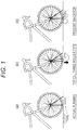
- Figs. 1(a) to 1(c) are drawings to describe the difference in trail of the three-roller bicycle trainer from the actual running.
- the trail affects the operational feeling of handlebar.
- the trail means a horizontal distance between a point where a steering axis of a steering tube is extended and intersects with a road surface and a point where a front wheel contacts the road surface (a point where a line vertically drawn from a wheel axis of the front wheel intersects with the road surface).
- a long trail enhances stability in straight running.
- a factor that the bicycle runs straight even if hands are released from the handlebar comes from the long trail.
- a short trail enhances maneuverability.
- a factor that a handling becomes light and quick comes from the shortness of the trail.
- the trail is the factor to determine the stability in straight running and steerability, and these factors are in a trade-off relationship. That is, although the long trail deteriorates the maneuverability, the stability in straight running is enhanced. Conversely, although the short trail deteriorates the stability in straight running, the steerability is enhanced.
- a point where the front wheel of the bicycle contacts the front wheel roller (hereinafter referred to as a "front wheel contact point”) is disposed forward with respect to a point where a line vertically drawn from a wheel axis of the front wheel intersects with the road surface.
- the trail becomes shorter than that of the actual running. Since the front wheel roller is disposed forward with respect to the front wheel, a force of sinking down the front wheel is generated. This generates the peculiar operational feeling of the handlebar different from the operational feeling in the actual running; therefore, the handlebar operation is likely to be mistaken. Due to these causes, the handlebar operation is likely to be mistaken with the three-roller bicycle trainer. Furthermore, once the posture of the bicycle is destabilized, a situation that the correction of the posture is difficult occurs.
- the present invention supports the front wheel of the bicycle with two front wheel rollers. This secures the trail in a state close to the actual running to improve the operational feeling of the handlebar.
- Fig. 2 is a drawing illustrating a state of contacting the front wheel of the bicycle with the front wheel rollers.
- the front wheel of the bicycle contacts the front wheel rollers at two points. This generates a straight movement force in the front wheel, allowing the trail to be secured in the state further close to the actual running.
- a bicycle trainer according to the invention 1 includes a pair of front wheel rollers that supports a front wheel of a bicycle, a pair of rear wheel rollers that supports a rear wheel of the bicycle, and a rotation synchronizing unit configured to synchronize a rotation of the front wheel rollers with a rotation of the rear wheel rollers.
- the present invention is applicable to a bicycle with a front wheel as a driving wheel, in addition to a bicycle with a rear wheel as the driving wheel. Furthermore, the present invention is also applicable to a bicycle with a rear wheel and a front wheel both working as the driving wheels.
- the rotation synchronizing unit includes, for example, a configuration that includes: (1) a belt that transmits the rotation of the rear wheel rollers to the front wheel rollers or (2) a detecting unit such as a rotary encoder that detects a rotating state of the rear wheel rollers and a driving unit such as a motor that rotates the front wheel rollers so as to synchronize with the rotation of the rear wheel rollers based on a detection result by the detecting unit.
- An application of the present invention to the bicycle with the front wheel as the driving wheel or an application of the bicycle with the rear wheel and the front wheel both working as the driving wheels also includes a configuration similar to these configurations.
- a bicycle trainer according to the invention 2 is the bicycle trainer according to the invention 1 configured as follows.
- the front wheel rollers support the front wheel of the bicycle such that a trail when the front wheel of the bicycle is put on the front wheel rollers becomes equivalent to a trail when the bicycle actually runs on a road surface.
- This configuration supports the front wheel of the bicycle such that the trail when the front wheel of the bicycle is put on the front wheel rollers and the rear wheel of the bicycle is put on the rear wheel rollers becomes equivalent to the trail in the actual running.
- the inventor has found that, with the first to third problems, one cause of the loss of the wheel comes from a change in distance between a point where the rear wheel of the bicycle contacts the rear wheel roller (hereinafter referred to as a "rear wheel contact point") and the front wheel contact point when the handlebar is turned.
- Figs. 3(a) and 3(b) are drawings to describe the change in distance between the rear wheel contact point and the front wheel contact point when the handlebar is turned.
- the distance between the rear wheel contact point and the front wheel contact point is a distance between the point where the line vertically drawn from the wheel axis of the front wheel intersects with the road surface and the point where the line vertically drawn from the wheel axis of the rear wheel intersects with the road surface.
- a fork offset means a horizontal distance between a point where a steering axis of a steering tube is extended and intersects with the road surface and a point where a line extended from the wheel axis of the front wheel parallel to the steering axis of the steering tube intersects with the road surface.
- the steering wheel angle of the handlebar changes the distance between the rear wheel contact point and the front wheel contact point.
- the three-roller bicycle trainer secures a position of the front wheel roller. Therefore, as the steering wheel angle of the handlebar increases, the front wheel contact point moves forward of the front wheel roller. This not only makes the trail short but also is likely to come off the wheel forward. It is considered that this is a cause of the wheel being likely to come off especially during the steering of the handlebar in the video in the above-described Internet site.
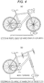
- Figs. 4(a) and 4(b) are drawings illustrating a configuration of moving the front wheel rollers following the change in distance between the rear wheel contact point and the front wheel contact point.
- the present invention moves the front wheel rollers following the change in distance between the rear wheel contact point and the front wheel contact point, thus causing the wheel to be less likely to come off even if the handlebar is turned. That is, as illustrated in Fig. 4(b) , when the handlebar is turned, the front wheel rollers move forward, the distance a is absorbed, and the two front wheel rollers always contact the front wheel at fixed positions.
- a bicycle trainer according to the invention 3 is the bicycle trainer according to any one of the inventions 1 and 2 that includes a front wheel roller adjusting unit.
- the front wheel roller adjusting unit is configured to adjust positions or postures of the front wheel rollers such that contact positions where the front wheel of the bicycle contacts the front wheel rollers become constant.
- the front wheel roller adjusting unit adjusts the positions or the postures of the front wheel rollers such that the contact positions where the front wheel of the bicycle contacts the front wheel rollers become constant.
- a bicycle trainer according to the invention 4 is the bicycle trainer according to the invention 3 configured as follows.
- the front wheel roller adjusting unit includes a front wheel roller support unit and a front wheel side biasing unit.
- the front wheel roller support unit supports the front wheel rollers such that the positions or the postures of the front wheel rollers are changeable.
- the front wheel side biasing unit biases the front wheel roller support unit such that the positions or the postures of the front wheel rollers return to reference positions or postures.
- the front wheel roller adjusting unit when the handlebar is turned, the front wheel roller adjusting unit is configured to adjust the positions or the postures of the front wheel rollers such that contact positions where the front wheel of the bicycle contacts the front wheel rollers become constant.
- a biasing force from the front wheel side biasing unit returns the positions or the postures of the front wheel rollers to the reference positions or postures. This enhances a following capability to the change in distance between the rear wheel contact point and the front wheel contact point.
- the inventor has found that one cause of the loss of the wheel in the fourth problem is as follows. Since the standing pedaling generates unevenness in the driving power of the bicycle and a fictitious force in the bicycle, the bicycle cannot resist the driving power or the fictitious force.
- the bicycle trainer since the standing pedaling generates the unevenness in the driving power of the bicycle and the fictitious force in the bicycle, the bicycle cannot resist the driving power or the fictitious force. This makes the wheel to be likely to come off in a front-rear direction. This is considered as a cause of the wheel being likely to come off especially during the standing pedaling in the video in the above-described Internet site.
- Fig. 5 is a drawing illustrating a configuration of moving the rear wheel rollers according to the driving power or the fictitious force of the bicycle.
- the present invention moves the rear wheel rollers according to the driving power or the fictitious force of the bicycle to make the wheel less likely to come off by the standing pedaling. That is, the standing pedaling moves the rear wheel rollers rearward and absorbs the unevenness in driving power and the fictitious force.
- the configuration of moving the rear wheel rollers is also effective to the problems of vibrations and noises.
- the three-roller bicycle trainer has problems of many rotating components and large vibrations and noises.
- the inventor has examined the problems in details. As a result, the inventor has found that a variation in rigidity of the rear wheel causes the problems.
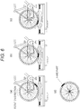
- Figs. 6(a) to 6(d) are drawings to describe a prevention of the vibrations and noises by moving the rear wheel rollers.
- a peripheral edge of a tire is partially hard. This is because that, in terms of a structure of the tire, the tire includes a non-uniformly deformed site due to a joint of a casing, a variation in rubber thickness, and the like. If this hard part in the tire passes through the rear wheel rollers, large vibrations and noises occur due to the impact.
- a bicycle trainer according to the invention 5 is the bicycle trainer according to any one of the inventions 1 to 4 that includes a rear wheel roller adjusting unit.
- the rear wheel roller adjusting unit is configured to adjust positions or postures of the rear wheel rollers according to a driving power or a fictitious force of the bicycle.
- the rear wheel roller adjusting unit adjusts the positions or the postures of the rear wheel rollers according to the driving power or the fictitious force of the bicycle.
- a bicycle trainer according to the invention 6 in the bicycle trainer according to the invention 5 is configured as follows.
- the rear wheel roller adjusting unit includes a rear wheel roller support unit and a rear wheel side biasing unit.
- the rear wheel roller support unit supports the rear wheel rollers such that the positions or the postures of the rear wheel rollers are changeable.
- the rear wheel side biasing unit biases the rear wheel roller support unit such that the positions or the postures of the rear wheel rollers return to reference positions or postures.
- a biasing force by the rear wheel side biasing unit returns the positions or the postures of the rear wheel rollers to the reference positions or postures. This enhances the following capability to the driving power or the fictitious force.
- a bicycle trainer according to the invention 7 in the bicycle trainer according to any one of the inventions 1 to 6 includes a front wheel frame, a rear wheel frame, and a coupling unit.
- the front wheel frame is to install the front wheel rollers.
- the rear wheel frame is to install the rear wheel rollers.
- the coupling unit couples the front wheel frame and the rear wheel frame together such that a height of the front wheel frame with respect to the rear wheel frame is adjustable.
- the coupling unit ensures adjusting the height of the front wheel frame with respect to the rear wheel frame. This ensures the self-standing running practice of the bicycle with a stance of simulating slopes.
- the bicycle trainer according to the inventions 1 to 7 supports the front wheel of the bicycle with the pair of front wheel rollers. This ensures securing the trail in the state close to the actual running. Furthermore, this ensures reducing a degree of difference in the operational feeling of the handlebar from the actual running. Additionally, the front wheel of the bicycle contacts the front wheel rollers at the two points. Therefore, the front wheel generates the straight movement force, thereby allowing the trail to secure the state further close to the actual running. Accordingly, compared with the typical bicycle trainer, the wheel is less likely to come off even during the low-speed running.
- the bicycle trainer according to the invention 2 supports the front wheel of the bicycle such that the trail becomes equivalent to that of the actual running. This ensures further reducing the degree of difference in the operational feeling of the handlebar from the actual running.
- the bicycle trainer according to the invention 3 or 4 adjusts the positions or the postures of the front wheel rollers such that the contact positions where the front wheel of the bicycle contacts the front wheel rollers constant. Accordingly, the wheel is less likely come off forward. This also ensures preventing the trail from shortening when the handlebar is turned. This ensures reducing the degree of difference in the operational feeling of the handlebar from the actual running. Furthermore, when the hard part of the front wheel passes through the front wheel rollers, the front wheel rollers move forward or change the postures to absorb the impact. This ensures the reduction in vibrations and noises.
- the bicycle trainer according to the invention 5 or 6 adjusts the positions or the postures of the rear wheel rollers according to the driving power or the fictitious force of the bicycle. This makes the wheel to be less likely to come off in the front-rear direction.
- the rear wheel rollers move rearward or change the postures to absorb the impact. This ensures the reduction in vibrations and noises.
- Fig. 7 to Fig. 10 are drawings illustrating the embodiment.
- Fig. 7 is a perspective view of a bicycle trainer 100.
- the bicycle trainer 100 includes a pair of front wheel rollers 10 and 12 to support a front wheel of a bicycle, a pair of rear wheel rollers 20 and 22 to support a rear wheel of the bicycle, a front wheel frame 30 to install the front wheel rollers 10 and 12, a rear wheel frame 40 to install the rear wheel rollers 20 and 22, and coupling frames 50 and 52 to couple the front wheel frame 30 and the rear wheel frame 40 together.
- the front wheel frame 30 includes a left frame 32 extending in a front-rear direction, a right frame 34 disposed parallel opposed to the left frame 32 with a predetermined interval, and a front frame 36 coupling a front end of the left frame 32 and a front end of the right frame 34 together.
- the left frame 32 includes a front wheel roller adjuster 14 to support left ends of the front wheel rollers 10 and 12.
- the right frame 34 includes a front wheel roller adjuster 16 to support right ends of the front wheel rollers 10 and 12.
- the front wheel rollers 10 and 12 are horizontally disposed such that their axial directions are perpendicular to the front-rear direction. It is preferable that the front wheel roller 10 be disposed forward with respect to the front wheel roller 12 and positioned forward around 10 to 20 [mm] by horizontal distance from a line vertically drawn from the wheel axis of the front wheel.
- the front wheel rollers 10 and 12 are disposed parallel to one another with the predetermined interval.
- a long distance between an axis of the front wheel roller 10 and an axis of the front wheel roller 12 (hereinafter referred to as a "distance between the front wheel rollers") lengthens the trail.
- a short distance between the front wheel rollers shortens the trail.
- the distance between the front wheel rollers is configured such that the trail when the front wheel of the bicycle is put on the front wheel rollers 10 and 12 becomes equivalent to the trail when the bicycle actually runs on a road surface.
- the distance between the front wheel rollers is preferably set to around 40 to 60 [mm].
- the rear wheel frame 40 includes a left frame 42 extending in the front-rear direction, a right frame 44 disposed parallel opposed to the left frame 42 with a predetermined interval, and a rear frame 46 coupling a rear end of the left frame 42 and a rear end of the right frame 44 together.
- the left frame 42 includes a rear wheel roller adjuster 24 to support left ends of the rear wheel rollers 20 and 22.
- the right frame 44 includes a rear wheel roller adjuster 26 to support right ends of the rear wheel rollers 20 and 22.
- the rear wheel rollers 20 and 22 are horizontally disposed such that their axial directions are perpendicular to the front-rear direction.
- the rear wheel roller 20 is disposed forward with respect to the rear wheel roller 22.
- the interval between the rear wheel rollers 20 and 22 is set such that the line vertically drawn from the wheel axis of the rear wheel is positioned at the center of the rear wheel rollers 20 and 22.
- the rear wheel rollers 20 and 22 are disposed parallel to one another with the predetermined interval.
- a distance between an axis of the rear wheel roller 20 and an axis of the rear wheel roller 22 (hereinafter referred to as a "distance between the rear wheel rollers") is preferably set to around 230 to 260 [mm].
- a pulley 60 with a diameter identical to that of the front wheel roller 10 is mounted concentrically with the front wheel roller 10 at the left end of the front wheel roller 10.
- a pulley 62 with a diameter identical to that of the front wheel roller 12 is mounted concentrically with the front wheel roller 12 at the left end of the front wheel roller 12.
- a pulley 64 with a diameter identical to that of the rear wheel roller 20 is mounted concentrically with the rear wheel roller 20 at the left end of the rear wheel roller 20.
- a belt 66 is wound around the pulleys 60 to 64. This transmits the rotation of the rear wheel roller 20 to the front wheel rollers 10 and 12 via the belt 66.
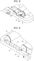
- Fig. 8 is a perspective view enlarging a periphery of the front wheel roller adjuster 16.
- the front wheel roller adjuster 16 adjusts the postures of the front wheel rollers 10 and 12 such that the contact positions where the front wheel of the bicycle contacts the front wheel rollers 10 and 12 become constant.
- the front wheel roller adjuster 16 includes a lower plate 16a secured to a top surface of the right frame 34, an L-shaped top plate 16b, and an elastic member 16c such as rubber.
- the L-shaped top plate 16b is formed of a side surface plate secured to shafts of the front wheel rollers 10 and 12 and a top surface plate orthogonally bent from an upper end of the side surface plate.
- the elastic member 16c is disposed between the lower plate 16a and the top surface plate of the L-shaped top plate 16b.
- An application of a forward load to the front wheel rollers 10 and 12 deforms the elastic member 16c and inclines the front wheel rollers 10 and 12 forward. Afterwards, when the forward load decreases, the biasing force (a restoring force) by the elastic member 16c returns the front wheel rollers 10 and 12 to the reference postures. Conversely, an application of a rearward load to the front wheel rollers 10 and 12 deforms the elastic member 16c and inclines the front wheel rollers 10 and 12 rearward. Afterwards, when the rearward load decreases, the biasing force by the elastic member 16c returns the front wheel rollers 10 and 12 to the reference postures.
- a groove 34a which extends in the front-rear direction, is formed on a top surface of the right frame 34.
- the lower plate 16a is secured to the right frame 34 via the groove 34a with a bolt or the like. This ensures securing the lower plate 16a to any given position in the groove 34a. This allows appropriately setting the positions of the front wheel rollers 10 and 12 according to a size of the bicycle.
- the front wheel roller adjuster 14 also has a configuration similar to the front wheel roller adjuster 16.
- Fig. 9 is a perspective view enlarging a periphery of the rear wheel roller adjuster 26.
- the rear wheel roller adjuster 26 adjusts the positions of the rear wheel rollers 20 and 22 according to the driving power or the fictitious force of the bicycle.
- the rear wheel roller adjuster 26 includes a coupling rod 26a and a parallel slide mechanism 26b such as a linear guide.
- the coupling rod 26a couples the shaft of the rear wheel roller 20 with the shaft of the rear wheel roller 22 together.
- the parallel slide mechanism 26b movably supports the coupling rod 26a in the front-rear direction.
- the parallel slide mechanism 26b is secured to a top surface of the right frame 44.
- the parallel slide mechanism 26b supports the coupling rod 26a to be movable forward and rearward.
- the parallel slide mechanism 26b biases the coupling rod 26a such that a position of the coupling rod 26a returns to the reference position.
- a moving amount of the coupling rod 26a is around 5 [mm] forward and around 5 [mm] rearward.
- An application of a forward load to the rear wheel rollers 20 and 22 moves the rear wheel rollers 20 and 22 forward according to the load. Afterwards, when the forward load decreases, the biasing force from the parallel slide mechanism 26b returns the rear wheel rollers 20 and 22 to the reference positions. Conversely, an application of a rearward load to the rear wheel rollers 20 and 22 moves the rear wheel rollers 20 and 22 rearward according to the load. Afterwards, when the rearward load decreases, the biasing force from the parallel slide mechanism 26b returns the rear wheel rollers 20 and 22 to the reference positions.
- a rear wheel roller adjuster 24 also has a configuration similar to the rear wheel roller adjuster 26.
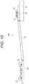
- Fig. 10 is a right side view of the bicycle trainer 100 in the case where the front wheel frame 30 is heightened.
- a front end of the coupling frame 50 is rotatably coupled to a rear end of the left frame 32.
- a rear end of the coupling frame 50 is rotatably coupled to a front end of the left frame 42.
- a front end of the coupling frame 52 is rotatably coupled to a rear end of the right frame 34.
- a rear end of the coupling frame 52 is rotatably coupled to a front end of the right frame 44.
- the bicycle trainer 100 bends with the rear end of the front wheel frame 30 and the front end of the rear wheel frame 40 as nodal points. This ensures adjusting a height of the front wheel frame 30 with respect to the rear wheel frame 40.
- installing the front wheel frame 30 on a base 70 allows the self-standing running practice of the bicycle with the stance simulating the slopes.
- the front wheel of the bicycle is supported such that the trail when the front wheel of the bicycle is put on the front wheel rollers 10 and 12 and the rear wheel of the bicycle is put on the rear wheel rollers 20 and 22 becomes equivalent to the trail in the actual running.
- Rotating the pedals rotates the rear wheel rollers 20 and 22 and drives the front wheel rollers 10 and 12 via the belt 66. This allows the self-standing running practice of the bicycle on the spot.
- the handlebar changes the distance between the rear wheel contact point and the front wheel contact point.
- the front wheel roller adjusters 14 and 16 adjust the postures of the front wheel rollers 10 and 12 such that the contact positions where the front wheel of the bicycle contacts the front wheel rollers 10 and 12 become constant. Returning the handlebar to the original position returns the postures of the front wheel rollers 10 and 12 to the reference postures by the biasing force from the elastic member 16c.
- the standing pedaling generates the unevenness in the driving power of the bicycle and generates the fictitious force in the bicycle.
- the rear wheel roller adjusters 24 and 26 adjust the positions of the rear wheel rollers 20 and 22 according to the driving power or the fictitious force of the bicycle.
- the biasing force by the parallel slide mechanism 26b returns the positions of the rear wheel rollers 20 and 22 to the reference positions.
- This embodiment includes the pair of front wheel rollers 10 and 12 to support the front wheel of the bicycle, the pair of rear wheel rollers 20 and 22 to support the rear wheel of the bicycle, and the belt 66 to transmit the rotation of the rear wheel roller 20 to the front wheel rollers 10 and 12.
- the front wheel rollers 10 and 12 support the front wheel of the bicycle such that the trail when the front wheel of the bicycle is put on the front wheel rollers 10 and 12 becomes equivalent to the trail when the bicycle actually runs on the road surface.
- this embodiment includes the front wheel roller adjusters 14 and 16.
- the front wheel roller adjusters 14 and 16 are configured to adjust the postures of the front wheel rollers 10 and 12 such that the contact positions where the front wheel of the bicycle contacts the front wheel rollers 10 and 12 become constant.
- the front wheel roller adjusters 14 and 16 support the front wheel rollers 10 and 12 such that the postures of the front wheel rollers 10 and 12 are changeable. Furthermore, the front wheel roller adjusters 14 and 16 bias the front wheel rollers 10 and 12 such that the postures of the front wheel rollers 10 and 12 return to the reference postures.
- the embodiment includes the rear wheel roller adjusters 24 and 26 that adjust the positions of the rear wheel rollers 20 and 22 according to the driving power or the fictitious force of the bicycle.
- the rear wheel roller adjusters 24 and 26 support the rear wheel rollers 20 and 22 such that the positions of the rear wheel rollers 20 and 22 are changeable. Further, the rear wheel roller adjusters 24 and 26 bias the rear wheel rollers 20 and 22 such that the positions of the rear wheel rollers 20 and 22 return to the reference positions.
- the biasing force by the parallel slide mechanism 26b returns the positions of the rear wheel rollers 20 and 22 to the reference positions. This enhances the following capability to the driving power or the fictitious force.
- this embodiment includes the front wheel frame 30, the rear wheel frame 40, and the coupling frames 50 and 52.
- the front wheel frame 30 is to install the front wheel rollers 10 and 12.
- the rear wheel frame 40 is to install the rear wheel rollers 20 and 22.
- the coupling frames 50 and 52 couple the front wheel frame 30 and the rear wheel frame 40 together such that the height of the front wheel frame 30 with respect to the rear wheel frame 40 is adjustable.
- the front wheel roller adjusters 14 and 16 correspond to the front wheel roller adjusting unit of the invention 3 or 4.
- the lower plate 16a and the L-shaped top plate 16b correspond to the front wheel roller support unit of the invention 4.
- the elastic member 16c corresponds to the front wheel side biasing unit of the invention 4.
- the rear wheel roller adjusters 24 and 26 correspond to the rear wheel roller adjusting unit of the invention 5 or 6.
- the coupling rod 26a and the parallel slide mechanism 26b correspond to the rear wheel roller support unit of the invention 6.
- the coupling frames 50 and 52 correspond to the coupling unit of the invention 7.
- the pulleys 60 to 64 and the belt 66 correspond to the rotation synchronizing unit of the invention 1.
- the above-described embodiment configures the front wheel roller adjusters 14 and 16 and the rear wheel roller adjusters 24 and 26 as illustrated in Fig. 8 and Fig. 9 .
- the configuration is not limited to this, and the following configuration can be employed. Since the front wheel roller adjuster 14 and the rear wheel roller adjuster 24 are configured similar to the front wheel roller adjuster 16 and the rear wheel roller adjuster 26, the following omits the explanation.
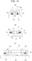
- Figs. 11 (a) to Fig. 12 are drawings illustrating modifications of the front wheel roller adjuster 16 and the rear wheel roller adjuster 26.
- the front wheel roller adjuster 16 includes a link plate 16d, a coupling plate 16e, an elastic member 16f such as a spring, and an elastic member 16g such as a spring.
- the link plate 16d is secured to a side surface of the right frame 34 and vertically extends upward from the right frame 34.
- the coupling plate 16e couples a shaft of the front wheel roller 10 with a shaft of the front wheel roller 12 together.
- a center of the coupling plate 16e is rotatably coupled to an upper end of the link plate 16d.
- the elastic member 16f is disposed between a front end of the coupling plate 16e and a top surface of the right frame 34.
- the elastic member 16g is disposed between a rear end of the coupling plate 16e and the top surface of the right frame 34.
- An application of a forward load to the front wheel rollers 10 and 12 deforms the elastic members 16f and 16g and inclines the front wheel rollers 10 and 12 forward. Afterwards, when the forward load decreases, the biasing force by the elastic members 16f and 16g returns the front wheel rollers 10 and 12 to the reference postures. Conversely, an application of a rearward load to the front wheel rollers 10 and 12 deforms the elastic members 16f and 16g and inclines the front wheel rollers 10 and 12 rearward. Afterwards, when the rearward load decreases, the biasing force by the elastic members 16f and 16g returns the front wheel rollers 10 and 12 to the reference postures.
- the front wheel roller adjuster 16 includes a lock plate 16h, a lock plate 16i, a coupling plate 16j, a parallel slide mechanism 16k such as a linear guide, an elastic member 161 such as a spring, and an elastic member 16m such as a spring.
- the lock plate 16h is secured to a top surface of the right frame 34 and is disposed forward of the front wheel roller 10.
- the lock plate 16i is secured to the top surface of the right frame 34 and is disposed rearward of the front wheel roller 12.
- the coupling plate 16j couples the shaft of the front wheel roller 10 and the shaft of the front wheel roller 12 together.
- the parallel slide mechanism 16k is secured to the top surface of the right frame 34 and movably supports the coupling plate 16j in the front-rear direction.
- the elastic member 161 is disposed between a front end of the coupling plate 16j and the lock plate 16h.
- the elastic member 16m is disposed between a rear end of the coupling plate 16j and the lock plate 16i.
- An application of a forward load to the front wheel rollers 10 and 12 moves the front wheel rollers 10 and 12 forward according to the load. Afterwards, when the forward load decreases, the biasing force by the elastic members 161 and 16m returns the front wheel rollers 10 and 12 to the reference positions. Conversely, an application of a rearward load to the front wheel rollers 10 and 12 moves the front wheel rollers 10 and 12 rearward according to the load. Afterwards, when the rearward load decreases, the biasing force by the elastic members 161 and 16m returns the front wheel rollers 10 and 12 to the reference positions.
- the rear wheel roller adjuster 26 includes a U-shaped sub-frame 26c, link plates 26d and 26e, a coupling frame 26f, an elastic member 26g such as a spring, and an elastic member 26h such as a spring.
- the U-shaped sub-frame 26c is secured to a top surface of the right frame 44.
- the link plates 26d and 26e are secured to a side surface of the sub-frame 26c and vertically extend from the sub-frame 26c downward.
- the coupling frame 26f couples a shaft of the rear wheel roller 20 and a shaft of the rear wheel roller 22 together.
- a front end and a rear end of the coupling frame 26f are rotatably coupled to lower ends of the link plates 26d and 26e, respectively.
- the elastic member 26g is disposed between the front end of the coupling frame 26f and the sub-frame 26c.
- the elastic member 26h is disposed between a rear end of the coupling frame 26f and the sub-frame 26c.
- An application of a forward load to the rear wheel rollers 20 and 22 moves the rear wheel rollers 20 and 22 forward according to the load. Afterwards, when the forward load decreases, the biasing force by the elastic members 26g and 26h returns the rear wheel rollers 20 and 22 to the reference positions. Conversely, an application of a rearward load to the rear wheel rollers 20 and 22 moves the rear wheel rollers 20 and 22 rearward according to the load. Afterwards, when the rearward load decreases, the biasing force by the elastic members 26g and 26h returns the rear wheel rollers 20 and 22 to the reference positions.
- a fourth configuration includes a coupling frame 50a, a link plate 50b, a coupling plate 50c, an elastic member 50d such as a spring, an elastic member 50e such as a spring, a base frame 50f, a lock plate 50g, a lock plate 50h, parallel slide mechanisms 50i and 50j such as a linear guide, an elastic member 50k such as a spring, and an elastic member 501 such as a spring.
- the coupling frame 50a couples the shaft of the rear wheel roller 20 and the shaft of the rear wheel roller 22 together.
- the link plate 50b is secured to a side surface of the coupling frame 50a and vertically extends from the coupling frame 50a upward.
- the coupling plate 50c couples the shaft of the front wheel roller 10 and the shaft of the front wheel roller 12 together.
- a center of the coupling plate 50c is rotatably coupled to an upper end of the link plate 50b.
- the elastic member 50d is disposed between a front end of the coupling plate 50c and a top surface of the coupling frame 50a.
- the elastic member 50e is disposed between a rear end of the coupling plate 50c and the top surface of the coupling frame 50a.
- the lock plate 50g is secured to the top surface of the base frame 50f and is disposed forward with respect to the front wheel roller 10.
- the lock plate 50h is secured to a top surface of the base frame 50f and is disposed rearward with respect to the front wheel roller 12.
- the parallel slide mechanisms 50i and 50j are secured to the top surface of the base frame 50f and movably support the coupling frame 50a in the front-rear direction.
- the elastic member 50k is disposed between a front end of the coupling frame 50a and the lock plate 50g.
- the elastic member 501 is disposed between a rear end of the coupling frame 50a and the lock plate 50h.
- An application of a forward load to the front wheel rollers 10 and 12 deforms the elastic members 50d and 50e and inclines the front wheel rollers 10 and 12 forward. Afterwards, when the forward load decreases, the biasing force by the elastic members 50d and 50e returns the front wheel rollers 10 and 12 to the reference postures. Conversely, an application of a rearward load to the front wheel rollers 10 and 12 deforms the elastic members 50d and 50e and inclines the front wheel rollers 10 and 12 rearward. Afterwards, when the rearward load decreases, the biasing force by the elastic members 50d and 50e returns the front wheel rollers 10 and 12 to the reference postures.
- An application of a forward load to the rear wheel rollers 20 and 22 moves the rear wheel rollers 20 and 22 forward according to the load. Afterwards, when the forward load decreases, the biasing force by the elastic members 50k and 501 returns the rear wheel rollers 20 and 22 to the reference positions. Conversely, an application of a rearward load to the rear wheel rollers 20 and 22 moves the rear wheel rollers 20 and 22 rearward according to the load. Afterwards, when the rearward load decreases, the biasing force by the elastic members 50k and 501 returns the rear wheel rollers 20 and 22 to the reference positions.
- the above-described embodiment and the modifications are configured to adjust the positions of the rear wheel rollers 20 and 22 by the rear wheel roller adjusters 24 and 26. However, this should not be constructed in a limiting sense. Like the front wheel roller adjusters 14 and 16, the rear wheel roller adjusters 24 and 26 can also be configured to adjust the postures of the rear wheel rollers 20 and 22.
Landscapes
- Health & Medical Sciences (AREA)
- General Health & Medical Sciences (AREA)
- Physical Education & Sports Medicine (AREA)
- Engineering & Computer Science (AREA)
- Mechanical Engineering (AREA)
- Motorcycle And Bicycle Frame (AREA)
Abstract
Description
- The present invention relates to a bicycle trainer for self-standing running practice of a bicycle and especially relates to a bicycle trainer with which a wheel is less likely to come off even during low-speed running.
- As a typical bicycle trainer, for example, techniques disclosed in PATENT LITERATURE 1 and NON-PATENT LITERATURE 1 have been known.
- The techniques disclosed in PATENT LITERATURE 1 and NON-PATENT LITERATURE 1 include one front wheel roller to support a front wheel of a bicycle, a pair of rear wheel rollers to support a rear wheel of the bicycle, and a belt to transmit a rotation of the rear wheel rollers to the front wheel roller. Putting the front wheel of the bicycle to the front wheel roller and the rear wheel of the bicycle to the rear wheel rollers and rotating pedals rotates the rear wheel rollers and drives the front wheel roller via the belt, thus ensuring self-standing running practice of the bicycle on the spot. Such bicycle trainer using the three rollers is referred to as a three-roller bicycle trainer.
- PATENT LITERATURE 1: JP-UM-A-2-77060
- NON-PATENT LITERATURE 1: "LiveRoll R700," [online], March, 2013, MINOURA JAPAN, searched through the Internet <URL:http://www.minoura.jp/japan/trainer/rollers/r700.html> on October 18, 2014
- However, the three-roller bicycle trainer has the following problems.
- First, an incorrect handlebar operation destabilizes a posture of the bicycle. If the posture of the bicycle is once destabilized, a correction of the posture is difficult and therefore a wheel is likely to come off.
- Secondly, there is a problem in which it is difficult to make a stable running without running the bicycle at a speed of 20 to 30 [km/h] or more to keep generating a gyro effect, due to the first problem.
- Thirdly, for training, an application of a load to the bicycle by a load device reduces the speed of the bicycle, making the stable running difficult due to the second problem.
- Fourthly, a riding out of saddle (standing pedaling) causes a problem that the wheel is likely to come off.
- A situation where the wheel is likely to come off with the three-roller bicycle trainer can be specifically confirmed at the Internet sites: "https://www.youtube.com/watch?v=USnC-OKOhaA" and "https://www.youtube.com/watch?v=fZKjnwJneZY".
- The present invention has focused on the unsolved problems that the known techniques have. An object of the present invention is to provide a bicycle trainer with which the wheel is less likely to come off even during low-speed running.
- Through intensive examinations, the inventor has hit upon the present invention based on the following knowledge.
- The inventor has found that one cause of the loss of the wheel in the first to third problems comes from peculiar operational feeling of handlebar different from operational feeling in actual running. Through further detailed examinations, the inventor has found that a cause of the operational feeling of handlebar being different from the operational feeling in the actual running comes from a difference in trail from the actual running.
-
Figs. 1(a) to 1(c) are drawings to describe the difference in trail of the three-roller bicycle trainer from the actual running. - The trail affects the operational feeling of handlebar. As illustrated in
Fig. 1(a) , the trail means a horizontal distance between a point where a steering axis of a steering tube is extended and intersects with a road surface and a point where a front wheel contacts the road surface (a point where a line vertically drawn from a wheel axis of the front wheel intersects with the road surface). A long trail enhances stability in straight running. A factor that the bicycle runs straight even if hands are released from the handlebar comes from the long trail. In contrast to this, a short trail enhances maneuverability. A factor that a handling becomes light and quick comes from the shortness of the trail. The trail is the factor to determine the stability in straight running and steerability, and these factors are in a trade-off relationship. That is, although the long trail deteriorates the maneuverability, the stability in straight running is enhanced. Conversely, although the short trail deteriorates the stability in straight running, the steerability is enhanced. - However, as illustrated in
Fig. 1(b) , in the three-roller bicycle trainer, a point where the front wheel of the bicycle contacts the front wheel roller (hereinafter referred to as a "front wheel contact point") is disposed forward with respect to a point where a line vertically drawn from a wheel axis of the front wheel intersects with the road surface. In view of this, with the three-roller bicycle trainer, the trail becomes shorter than that of the actual running. Since the front wheel roller is disposed forward with respect to the front wheel, a force of sinking down the front wheel is generated. This generates the peculiar operational feeling of the handlebar different from the operational feeling in the actual running; therefore, the handlebar operation is likely to be mistaken. Due to these causes, the handlebar operation is likely to be mistaken with the three-roller bicycle trainer. Furthermore, once the posture of the bicycle is destabilized, a situation that the correction of the posture is difficult occurs. - Therefore, as illustrated in
Fig. 1(c) , the present invention supports the front wheel of the bicycle with two front wheel rollers. This secures the trail in a state close to the actual running to improve the operational feeling of the handlebar. -
Fig. 2 is a drawing illustrating a state of contacting the front wheel of the bicycle with the front wheel rollers. - Furthermore, as illustrated in
Fig. 2 , with the configuration that the two front wheel rollers support the front wheel of the bicycle, the front wheel of the bicycle contacts the front wheel rollers at two points. This generates a straight movement force in the front wheel, allowing the trail to be secured in the state further close to the actual running. - To achieve the object, a bicycle trainer according to the invention 1 includes a pair of front wheel rollers that supports a front wheel of a bicycle, a pair of rear wheel rollers that supports a rear wheel of the bicycle, and a rotation synchronizing unit configured to synchronize a rotation of the front wheel rollers with a rotation of the rear wheel rollers.
- With this configuration, putting the front wheel of the bicycle to the front wheel rollers and the rear wheel of the bicycle to the rear wheel rollers and rotating pedals rotates one of the rollers and drives the other rollers by the rotation synchronizing unit, allowing the self-standing running practice of the bicycle on the spot.
- The present invention is applicable to a bicycle with a front wheel as a driving wheel, in addition to a bicycle with a rear wheel as the driving wheel. Furthermore, the present invention is also applicable to a bicycle with a rear wheel and a front wheel both working as the driving wheels.
- The rotation synchronizing unit includes, for example, a configuration that includes: (1) a belt that transmits the rotation of the rear wheel rollers to the front wheel rollers or (2) a detecting unit such as a rotary encoder that detects a rotating state of the rear wheel rollers and a driving unit such as a motor that rotates the front wheel rollers so as to synchronize with the rotation of the rear wheel rollers based on a detection result by the detecting unit. An application of the present invention to the bicycle with the front wheel as the driving wheel or an application of the bicycle with the rear wheel and the front wheel both working as the driving wheels also includes a configuration similar to these configurations.
- Furthermore, a bicycle trainer according to the invention 2 is the bicycle trainer according to the invention 1 configured as follows. The front wheel rollers support the front wheel of the bicycle such that a trail when the front wheel of the bicycle is put on the front wheel rollers becomes equivalent to a trail when the bicycle actually runs on a road surface.
- This configuration supports the front wheel of the bicycle such that the trail when the front wheel of the bicycle is put on the front wheel rollers and the rear wheel of the bicycle is put on the rear wheel rollers becomes equivalent to the trail in the actual running.
- Through the intensive examinations, the inventor has hit upon the present invention based on the following knowledge.
- The inventor has found that, with the first to third problems, one cause of the loss of the wheel comes from a change in distance between a point where the rear wheel of the bicycle contacts the rear wheel roller (hereinafter referred to as a "rear wheel contact point") and the front wheel contact point when the handlebar is turned.
-
Figs. 3(a) and 3(b) are drawings to describe the change in distance between the rear wheel contact point and the front wheel contact point when the handlebar is turned. - With a steering wheel angle of the handlebar of 0 degrees, as illustrated in
Fig. 3(a) , the distance between the rear wheel contact point and the front wheel contact point is a distance between the point where the line vertically drawn from the wheel axis of the front wheel intersects with the road surface and the point where the line vertically drawn from the wheel axis of the rear wheel intersects with the road surface. - In contrast to this, with the steering wheel angle of the handlebar of 90 degrees, as illustrated in
Fig. 3(b) , the distance between the rear wheel contact point and the front wheel contact point becomes longer than the distance with the steering wheel angle of the handlebar of 0 degrees by a distance a . The distance a can be obtained by the following formula (1). In the following formula (1), a fork offset means a horizontal distance between a point where a steering axis of a steering tube is extended and intersects with the road surface and a point where a line extended from the wheel axis of the front wheel parallel to the steering axis of the steering tube intersects with the road surface.
- For example, with 27-inch road bike, a = (350 [mm] × sin 18 [°]) - 50 [mm] ≈ 58 [mm] is met.
- Thus, the steering wheel angle of the handlebar changes the distance between the rear wheel contact point and the front wheel contact point. In despite of this, the three-roller bicycle trainer secures a position of the front wheel roller. Therefore, as the steering wheel angle of the handlebar increases, the front wheel contact point moves forward of the front wheel roller. This not only makes the trail short but also is likely to come off the wheel forward. It is considered that this is a cause of the wheel being likely to come off especially during the steering of the handlebar in the video in the above-described Internet site.
-
Figs. 4(a) and 4(b) are drawings illustrating a configuration of moving the front wheel rollers following the change in distance between the rear wheel contact point and the front wheel contact point. - As illustrated in
Figs. 4(a) and 4(b) , the present invention moves the front wheel rollers following the change in distance between the rear wheel contact point and the front wheel contact point, thus causing the wheel to be less likely to come off even if the handlebar is turned. That is, as illustrated inFig. 4(b) , when the handlebar is turned, the front wheel rollers move forward, the distance a is absorbed, and the two front wheel rollers always contact the front wheel at fixed positions. - Furthermore, a bicycle trainer according to the invention 3 is the bicycle trainer according to any one of the inventions 1 and 2 that includes a front wheel roller adjusting unit. The front wheel roller adjusting unit is configured to adjust positions or postures of the front wheel rollers such that contact positions where the front wheel of the bicycle contacts the front wheel rollers become constant.
- With this configuration, when the handlebar is turned, the front wheel roller adjusting unit adjusts the positions or the postures of the front wheel rollers such that the contact positions where the front wheel of the bicycle contacts the front wheel rollers become constant.
- Furthermore, a bicycle trainer according to the invention 4 is the bicycle trainer according to the invention 3 configured as follows. The front wheel roller adjusting unit includes a front wheel roller support unit and a front wheel side biasing unit. The front wheel roller support unit supports the front wheel rollers such that the positions or the postures of the front wheel rollers are changeable. The front wheel side biasing unit biases the front wheel roller support unit such that the positions or the postures of the front wheel rollers return to reference positions or postures.
- With this configuration, when the handlebar is turned, the front wheel roller adjusting unit is configured to adjust the positions or the postures of the front wheel rollers such that contact positions where the front wheel of the bicycle contacts the front wheel rollers become constant. When the handlebar is returned to an original position, a biasing force from the front wheel side biasing unit returns the positions or the postures of the front wheel rollers to the reference positions or postures. This enhances a following capability to the change in distance between the rear wheel contact point and the front wheel contact point.
- Through intensive examinations, the inventor has hit upon the present invention based on the following knowledge.
- The inventor has found that one cause of the loss of the wheel in the fourth problem is as follows. Since the standing pedaling generates unevenness in the driving power of the bicycle and a fictitious force in the bicycle, the bicycle cannot resist the driving power or the fictitious force.
- With the three-roller bicycle trainer, since the standing pedaling generates the unevenness in the driving power of the bicycle and the fictitious force in the bicycle, the bicycle cannot resist the driving power or the fictitious force. This makes the wheel to be likely to come off in a front-rear direction. This is considered as a cause of the wheel being likely to come off especially during the standing pedaling in the video in the above-described Internet site.
-
Fig. 5 is a drawing illustrating a configuration of moving the rear wheel rollers according to the driving power or the fictitious force of the bicycle. - As illustrated in
Fig. 5 , the present invention moves the rear wheel rollers according to the driving power or the fictitious force of the bicycle to make the wheel less likely to come off by the standing pedaling. That is, the standing pedaling moves the rear wheel rollers rearward and absorbs the unevenness in driving power and the fictitious force. - The configuration of moving the rear wheel rollers is also effective to the problems of vibrations and noises.
- The three-roller bicycle trainer has problems of many rotating components and large vibrations and noises.
- Therefore, to solve the problems of the vibrations and noises, the inventor has examined the problems in details. As a result, the inventor has found that a variation in rigidity of the rear wheel causes the problems.
-
Figs. 6(a) to 6(d) are drawings to describe a prevention of the vibrations and noises by moving the rear wheel rollers. - As illustrated in
Fig. 6(d) , a peripheral edge of a tire is partially hard. This is because that, in terms of a structure of the tire, the tire includes a non-uniformly deformed site due to a joint of a casing, a variation in rubber thickness, and the like. If this hard part in the tire passes through the rear wheel rollers, large vibrations and noises occur due to the impact. - In contrast to this, as illustrated in
Figs. 6(a) to 6(c) , when this hard part in the rear wheel passes through the rear wheel rollers, the rear wheel rollers move rearward and absorb the impact. With the three-roller bicycle trainer, this allows impact energy transmitted to a floor to be converted into the energy in the front-rear direction, thereby ensuring reducing the vibrations and noises. With the front wheel side as well, when this hard part in the front wheel passes through the front wheel rollers, the front wheel rollers move forward and absorb the impact. This ensures obtaining the similar effect. - Furthermore, a bicycle trainer according to the invention 5 is the bicycle trainer according to any one of the inventions 1 to 4 that includes a rear wheel roller adjusting unit. The rear wheel roller adjusting unit is configured to adjust positions or postures of the rear wheel rollers according to a driving power or a fictitious force of the bicycle.
- With this configuration, when the standing pedaling is performed, the rear wheel roller adjusting unit adjusts the positions or the postures of the rear wheel rollers according to the driving power or the fictitious force of the bicycle.
- Furthermore, a bicycle trainer according to the invention 6 in the bicycle trainer according to the invention 5 is configured as follows. The rear wheel roller adjusting unit includes a rear wheel roller support unit and a rear wheel side biasing unit. The rear wheel roller support unit supports the rear wheel rollers such that the positions or the postures of the rear wheel rollers are changeable. The rear wheel side biasing unit biases the rear wheel roller support unit such that the positions or the postures of the rear wheel rollers return to reference positions or postures.
- With this configuration, according to the driving power or the fictitious force of the bicycle, even if the positions or the postures of the rear wheel rollers change, when the driving power or the fictitious force decreases, a biasing force by the rear wheel side biasing unit returns the positions or the postures of the rear wheel rollers to the reference positions or postures. This enhances the following capability to the driving power or the fictitious force.
- Furthermore, a bicycle trainer according to the invention 7 in the bicycle trainer according to any one of the inventions 1 to 6 includes a front wheel frame, a rear wheel frame, and a coupling unit. The front wheel frame is to install the front wheel rollers. The rear wheel frame is to install the rear wheel rollers. The coupling unit couples the front wheel frame and the rear wheel frame together such that a height of the front wheel frame with respect to the rear wheel frame is adjustable.
- With this configuration, the coupling unit ensures adjusting the height of the front wheel frame with respect to the rear wheel frame. This ensures the self-standing running practice of the bicycle with a stance of simulating slopes.
- As described above, the bicycle trainer according to the inventions 1 to 7 supports the front wheel of the bicycle with the pair of front wheel rollers. This ensures securing the trail in the state close to the actual running. Furthermore, this ensures reducing a degree of difference in the operational feeling of the handlebar from the actual running. Additionally, the front wheel of the bicycle contacts the front wheel rollers at the two points. Therefore, the front wheel generates the straight movement force, thereby allowing the trail to secure the state further close to the actual running. Accordingly, compared with the typical bicycle trainer, the wheel is less likely to come off even during the low-speed running.
- Furthermore, the bicycle trainer according to the invention 2 supports the front wheel of the bicycle such that the trail becomes equivalent to that of the actual running. This ensures further reducing the degree of difference in the operational feeling of the handlebar from the actual running.
- Furthermore, even when the handlebar turned, the bicycle trainer according to the invention 3 or 4 adjusts the positions or the postures of the front wheel rollers such that the contact positions where the front wheel of the bicycle contacts the front wheel rollers constant. Accordingly, the wheel is less likely come off forward. This also ensures preventing the trail from shortening when the handlebar is turned. This ensures reducing the degree of difference in the operational feeling of the handlebar from the actual running. Furthermore, when the hard part of the front wheel passes through the front wheel rollers, the front wheel rollers move forward or change the postures to absorb the impact. This ensures the reduction in vibrations and noises.
- Furthermore, even when the standing pedaling is performed, the bicycle trainer according to the invention 5 or 6 adjusts the positions or the postures of the rear wheel rollers according to the driving power or the fictitious force of the bicycle. This makes the wheel to be less likely to come off in the front-rear direction. When the hard part of the rear wheel passes through the rear wheel rollers, the rear wheel rollers move rearward or change the postures to absorb the impact. This ensures the reduction in vibrations and noises.
-
-
Figs. 1(a) to 1(c) are drawings to describe a difference in trail in a three-roller bicycle trainer from actual running. -
Fig. 2 is a drawing illustrating a state of contacting a front wheel of a bicycle with front wheel rollers. -
Figs. 3(a) and 3(b) are drawings to describe a change in distance between a rear wheel contact point and a front wheel contact point when a handlebar is turned. -
Figs. 4(a) and 4(b) are drawings illustrating a configuration of moving the front wheel rollers following the change in the distance between the rear wheel contact point and the front wheel contact point. -
Fig. 5 is a drawing illustrating a configuration of moving rear wheel rollers according to a driving power or a fictitious force of the bicycle. -
Figs. 6(a) to 6(d) are drawings to describe a prevention of vibrations and noises by moving the rear wheel rollers. -
Fig. 7 is a perspective view of abicycle trainer 100. -
Fig. 8 is a perspective view enlarging a periphery of a frontwheel roller adjuster 16. -
Fig. 9 is a perspective view enlarging a periphery of a rearwheel roller adjuster 26. -
Fig. 10 is a right side view of thebicycle trainer 100 in the case where afront wheel frame 30 is heightened. -
Figs. 11(a) to 11(c) are drawings illustrating modifications of the frontwheel roller adjuster 16 and the rearwheel roller adjuster 26. -
Fig. 12 is a drawing illustrating modifications of the frontwheel roller adjuster 16 and the rearwheel roller adjuster 26. - The following describes an embodiment of the present invention.
Fig. 7 to Fig. 10 are drawings illustrating the embodiment. - First, the following describes a configuration of the embodiment.
-
Fig. 7 is a perspective view of abicycle trainer 100. - As illustrated in
Fig. 7 , thebicycle trainer 100 includes a pair offront wheel rollers rear wheel rollers front wheel frame 30 to install thefront wheel rollers rear wheel frame 40 to install therear wheel rollers front wheel frame 30 and therear wheel frame 40 together. - The
front wheel frame 30 includes aleft frame 32 extending in a front-rear direction, aright frame 34 disposed parallel opposed to theleft frame 32 with a predetermined interval, and afront frame 36 coupling a front end of theleft frame 32 and a front end of theright frame 34 together. Theleft frame 32 includes a frontwheel roller adjuster 14 to support left ends of thefront wheel rollers right frame 34 includes a frontwheel roller adjuster 16 to support right ends of thefront wheel rollers - The
front wheel rollers front wheel roller 10 be disposed forward with respect to thefront wheel roller 12 and positioned forward around 10 to 20 [mm] by horizontal distance from a line vertically drawn from the wheel axis of the front wheel. - The
front wheel rollers front wheel roller 10 and an axis of the front wheel roller 12 (hereinafter referred to as a "distance between the front wheel rollers") lengthens the trail. A short distance between the front wheel rollers shortens the trail. In view of this, the distance between the front wheel rollers is configured such that the trail when the front wheel of the bicycle is put on thefront wheel rollers - The
rear wheel frame 40 includes aleft frame 42 extending in the front-rear direction, aright frame 44 disposed parallel opposed to theleft frame 42 with a predetermined interval, and arear frame 46 coupling a rear end of theleft frame 42 and a rear end of theright frame 44 together. Theleft frame 42 includes a rearwheel roller adjuster 24 to support left ends of therear wheel rollers right frame 44 includes a rearwheel roller adjuster 26 to support right ends of therear wheel rollers - The
rear wheel rollers rear wheel roller 20 is disposed forward with respect to therear wheel roller 22. The interval between therear wheel rollers rear wheel rollers - The
rear wheel rollers rear wheel roller 20 and an axis of the rear wheel roller 22 (hereinafter referred to as a "distance between the rear wheel rollers") is preferably set to around 230 to 260 [mm]. - A
pulley 60 with a diameter identical to that of thefront wheel roller 10 is mounted concentrically with thefront wheel roller 10 at the left end of thefront wheel roller 10. Apulley 62 with a diameter identical to that of thefront wheel roller 12 is mounted concentrically with thefront wheel roller 12 at the left end of thefront wheel roller 12. Apulley 64 with a diameter identical to that of therear wheel roller 20 is mounted concentrically with therear wheel roller 20 at the left end of therear wheel roller 20. Abelt 66 is wound around thepulleys 60 to 64. This transmits the rotation of therear wheel roller 20 to thefront wheel rollers belt 66. -
Fig. 8 is a perspective view enlarging a periphery of the frontwheel roller adjuster 16. - The front
wheel roller adjuster 16 adjusts the postures of thefront wheel rollers front wheel rollers - As illustrated in
Fig. 8 , the frontwheel roller adjuster 16 includes alower plate 16a secured to a top surface of theright frame 34, an L-shapedtop plate 16b, and anelastic member 16c such as rubber. The L-shapedtop plate 16b is formed of a side surface plate secured to shafts of thefront wheel rollers elastic member 16c is disposed between thelower plate 16a and the top surface plate of the L-shapedtop plate 16b. - An application of a forward load to the
front wheel rollers elastic member 16c and inclines thefront wheel rollers elastic member 16c returns thefront wheel rollers front wheel rollers elastic member 16c and inclines thefront wheel rollers elastic member 16c returns thefront wheel rollers - A
groove 34a, which extends in the front-rear direction, is formed on a top surface of theright frame 34. Thelower plate 16a is secured to theright frame 34 via thegroove 34a with a bolt or the like. This ensures securing thelower plate 16a to any given position in thegroove 34a. This allows appropriately setting the positions of thefront wheel rollers - The front
wheel roller adjuster 14 also has a configuration similar to the frontwheel roller adjuster 16. -
Fig. 9 is a perspective view enlarging a periphery of the rearwheel roller adjuster 26. - The rear
wheel roller adjuster 26 adjusts the positions of therear wheel rollers - As illustrated in
Fig. 9 , the rearwheel roller adjuster 26 includes acoupling rod 26a and aparallel slide mechanism 26b such as a linear guide. Thecoupling rod 26a couples the shaft of therear wheel roller 20 with the shaft of therear wheel roller 22 together. Theparallel slide mechanism 26b movably supports thecoupling rod 26a in the front-rear direction. - The
parallel slide mechanism 26b is secured to a top surface of theright frame 44. Theparallel slide mechanism 26b supports thecoupling rod 26a to be movable forward and rearward. Theparallel slide mechanism 26b biases thecoupling rod 26a such that a position of thecoupling rod 26a returns to the reference position. A moving amount of thecoupling rod 26a is around 5 [mm] forward and around 5 [mm] rearward. - An application of a forward load to the
rear wheel rollers rear wheel rollers parallel slide mechanism 26b returns therear wheel rollers rear wheel rollers rear wheel rollers parallel slide mechanism 26b returns therear wheel rollers - A rear
wheel roller adjuster 24 also has a configuration similar to the rearwheel roller adjuster 26. -
Fig. 10 is a right side view of thebicycle trainer 100 in the case where thefront wheel frame 30 is heightened. - A front end of the
coupling frame 50 is rotatably coupled to a rear end of theleft frame 32. A rear end of thecoupling frame 50 is rotatably coupled to a front end of theleft frame 42. Similarly, a front end of thecoupling frame 52 is rotatably coupled to a rear end of theright frame 34. A rear end of thecoupling frame 52 is rotatably coupled to a front end of theright frame 44. Accordingly, as illustrated inFig. 10 , thebicycle trainer 100 bends with the rear end of thefront wheel frame 30 and the front end of therear wheel frame 40 as nodal points. This ensures adjusting a height of thefront wheel frame 30 with respect to therear wheel frame 40. For example, as illustrated inFig. 10 , installing thefront wheel frame 30 on abase 70 allows the self-standing running practice of the bicycle with the stance simulating the slopes. - The following describes operations of the embodiment.
- The front wheel of the bicycle is supported such that the trail when the front wheel of the bicycle is put on the
front wheel rollers rear wheel rollers rear wheel rollers front wheel rollers belt 66. This allows the self-standing running practice of the bicycle on the spot. - Turning the handlebar changes the distance between the rear wheel contact point and the front wheel contact point. However, the front
wheel roller adjusters front wheel rollers front wheel rollers front wheel rollers elastic member 16c. - The standing pedaling generates the unevenness in the driving power of the bicycle and generates the fictitious force in the bicycle. However, the rear
wheel roller adjusters rear wheel rollers parallel slide mechanism 26b returns the positions of therear wheel rollers - The following describes effects of the embodiment.
- This embodiment includes the pair of
front wheel rollers rear wheel rollers belt 66 to transmit the rotation of therear wheel roller 20 to thefront wheel rollers - This supports the front wheel of the bicycle by the pair of
front wheel rollers front wheel rollers bicycle trainer 100, making a high-load self-standing running practice possible. - Furthermore, in this embodiment, the
front wheel rollers front wheel rollers - This supports the front wheel of the bicycle such that the trail becomes equivalent to that of the actual running. This ensures further reducing the degree of difference in the operational feeling of the handlebar from the actual running.
- Furthermore, this embodiment includes the front
wheel roller adjusters wheel roller adjusters front wheel rollers front wheel rollers - This adjusts the postures of the
front wheel rollers front wheel rollers front wheel rollers front wheel rollers - Furthermore, with the embodiment, the front
wheel roller adjusters front wheel rollers front wheel rollers wheel roller adjusters front wheel rollers front wheel rollers - Therefore, returning the handlebar to the original position returns the postures of the
front wheel rollers elastic member 16c. This enhances the following capability to the change in distance between the rear wheel contact point and the front wheel contact point. - Furthermore, the embodiment includes the rear
wheel roller adjusters rear wheel rollers - Even when the standing pedaling is performed, this adjusts the positions of the
rear wheel rollers rear wheel rollers rear wheel rollers - Furthermore, with the embodiment, the rear
wheel roller adjusters rear wheel rollers rear wheel rollers wheel roller adjusters rear wheel rollers rear wheel rollers - Therefore, according to the driving power or the fictitious force of the bicycle, even if the positions of the
rear wheel rollers parallel slide mechanism 26b returns the positions of therear wheel rollers - Furthermore, this embodiment includes the
front wheel frame 30, therear wheel frame 40, and the coupling frames 50 and 52. Thefront wheel frame 30 is to install thefront wheel rollers rear wheel frame 40 is to install therear wheel rollers front wheel frame 30 and therear wheel frame 40 together such that the height of thefront wheel frame 30 with respect to therear wheel frame 40 is adjustable. - This ensures adjusting the height of the
front wheel frame 30 with respect to therear wheel frame 40. This ensures the self-standing running practice of the bicycle with the stance of simulating the slopes. - In the embodiment, the front
wheel roller adjusters lower plate 16a and the L-shapedtop plate 16b correspond to the front wheel roller support unit of the invention 4. Theelastic member 16c corresponds to the front wheel side biasing unit of the invention 4. The rearwheel roller adjusters coupling rod 26a and theparallel slide mechanism 26b correspond to the rear wheel roller support unit of the invention 6. The coupling frames 50 and 52 correspond to the coupling unit of the invention 7. Thepulleys 60 to 64 and thebelt 66 correspond to the rotation synchronizing unit of the invention 1. - The above-described embodiment configures the front
wheel roller adjusters wheel roller adjusters Fig. 8 and Fig. 9 . However, the configuration is not limited to this, and the following configuration can be employed. Since the frontwheel roller adjuster 14 and the rearwheel roller adjuster 24 are configured similar to the frontwheel roller adjuster 16 and the rearwheel roller adjuster 26, the following omits the explanation. -
Figs. 11 (a) toFig. 12 are drawings illustrating modifications of the frontwheel roller adjuster 16 and the rearwheel roller adjuster 26. - As a first configuration, as illustrated in
Fig. 11(a) , the frontwheel roller adjuster 16 includes alink plate 16d, acoupling plate 16e, anelastic member 16f such as a spring, and anelastic member 16g such as a spring. Thelink plate 16d is secured to a side surface of theright frame 34 and vertically extends upward from theright frame 34. Thecoupling plate 16e couples a shaft of thefront wheel roller 10 with a shaft of thefront wheel roller 12 together. A center of thecoupling plate 16e is rotatably coupled to an upper end of thelink plate 16d. Theelastic member 16f is disposed between a front end of thecoupling plate 16e and a top surface of theright frame 34. Theelastic member 16g is disposed between a rear end of thecoupling plate 16e and the top surface of theright frame 34. - An application of a forward load to the
front wheel rollers elastic members front wheel rollers elastic members front wheel rollers front wheel rollers elastic members front wheel rollers elastic members front wheel rollers - As a second configuration, as illustrated in
Fig. 11(b) , the frontwheel roller adjuster 16 includes alock plate 16h, alock plate 16i, acoupling plate 16j, aparallel slide mechanism 16k such as a linear guide, anelastic member 161 such as a spring, and anelastic member 16m such as a spring. Thelock plate 16h is secured to a top surface of theright frame 34 and is disposed forward of thefront wheel roller 10. Thelock plate 16i is secured to the top surface of theright frame 34 and is disposed rearward of thefront wheel roller 12. Thecoupling plate 16j couples the shaft of thefront wheel roller 10 and the shaft of thefront wheel roller 12 together. Theparallel slide mechanism 16k is secured to the top surface of theright frame 34 and movably supports thecoupling plate 16j in the front-rear direction. Theelastic member 161 is disposed between a front end of thecoupling plate 16j and thelock plate 16h. Theelastic member 16m is disposed between a rear end of thecoupling plate 16j and thelock plate 16i. - An application of a forward load to the
front wheel rollers front wheel rollers elastic members front wheel rollers front wheel rollers front wheel rollers elastic members front wheel rollers - As a third configuration, as illustrated in
Fig. 11 (c) , the rearwheel roller adjuster 26 includes aU-shaped sub-frame 26c,link plates coupling frame 26f, anelastic member 26g such as a spring, and anelastic member 26h such as a spring. TheU-shaped sub-frame 26c is secured to a top surface of theright frame 44. Thelink plates sub-frame 26c and vertically extend from thesub-frame 26c downward. Thecoupling frame 26f couples a shaft of therear wheel roller 20 and a shaft of therear wheel roller 22 together. A front end and a rear end of thecoupling frame 26f are rotatably coupled to lower ends of thelink plates elastic member 26g is disposed between the front end of thecoupling frame 26f and thesub-frame 26c. Theelastic member 26h is disposed between a rear end of thecoupling frame 26f and thesub-frame 26c. - An application of a forward load to the
rear wheel rollers rear wheel rollers elastic members rear wheel rollers rear wheel rollers rear wheel rollers elastic members rear wheel rollers - Instead of the front
wheel roller adjuster 16 and the rearwheel roller adjuster 26, as illustrated inFig. 12 , a fourth configuration includes acoupling frame 50a, alink plate 50b, acoupling plate 50c, anelastic member 50d such as a spring, anelastic member 50e such as a spring, abase frame 50f, alock plate 50g, alock plate 50h,parallel slide mechanisms elastic member 50k such as a spring, and anelastic member 501 such as a spring. Thecoupling frame 50a couples the shaft of therear wheel roller 20 and the shaft of therear wheel roller 22 together. Thelink plate 50b is secured to a side surface of thecoupling frame 50a and vertically extends from thecoupling frame 50a upward. Thecoupling plate 50c couples the shaft of thefront wheel roller 10 and the shaft of thefront wheel roller 12 together. A center of thecoupling plate 50c is rotatably coupled to an upper end of thelink plate 50b. Theelastic member 50d is disposed between a front end of thecoupling plate 50c and a top surface of thecoupling frame 50a. Theelastic member 50e is disposed between a rear end of thecoupling plate 50c and the top surface of thecoupling frame 50a. Thelock plate 50g is secured to the top surface of thebase frame 50f and is disposed forward with respect to thefront wheel roller 10. Thelock plate 50h is secured to a top surface of thebase frame 50f and is disposed rearward with respect to thefront wheel roller 12. Theparallel slide mechanisms base frame 50f and movably support thecoupling frame 50a in the front-rear direction. Theelastic member 50k is disposed between a front end of thecoupling frame 50a and thelock plate 50g. Theelastic member 501 is disposed between a rear end of thecoupling frame 50a and thelock plate 50h. - An application of a forward load to the
front wheel rollers elastic members front wheel rollers elastic members front wheel rollers front wheel rollers elastic members front wheel rollers elastic members front wheel rollers - An application of a forward load to the
rear wheel rollers rear wheel rollers elastic members rear wheel rollers rear wheel rollers rear wheel rollers elastic members rear wheel rollers - The above-described embodiment and the modifications are configured to adjust the positions of the
rear wheel rollers wheel roller adjusters wheel roller adjusters wheel roller adjusters rear wheel rollers -
- 100:
- Bicycle trainer
- 10, 12:
- Front wheel roller
- 14, 16:
- Front wheel roller adjuster
- 16a:
- Lower plate
- 16b:
- L-shaped top plate
- 16c, 16f, 16g, 161, 16m, 26g, 26h, 50d, 50e, 50k, 501:
- Elastic member
- 16d, 26d, 26e, 50b:
- Link plate
- 16e, 16j, 50c:
- Coupling plate
- 16h, 16i, 50g, 50h:
- Lock plate
- 16k, 26b, 50i, 50j:
- Parallel slide mechanism
- 20, 22:
- Rear wheel roller
- 24, 26:
- Rear wheel roller adjuster
- 26a:
- Coupling rod
- 26c:
- Sub-frame
- 26f, 50a, 50, 52:
- Coupling frame
- 30:
- Front wheel frame
- 32:
- Left frame
- 34:
- Right frame
- 34a:
- Groove
- 36:
- Front frame
- 40:
- Rear wheel frame
- 42:
- Left frame
- 44:
- Right frame
- 46:
- Rear frame
- 50f:
- Base frame
- 60 to 64:
- Pulley
- 66:
- Belt
- 70:
- Base
Claims (7)
- A bicycle trainer comprising:a pair of front wheel rollers that supports a front wheel of a bicycle;a pair of rear wheel rollers that supports a rear wheel of the bicycle; anda rotation synchronizing unit configured to synchronize a rotation of the front wheel rollers with a rotation of the rear wheel rollers.
- The bicycle trainer according to claim 1, wherein
the front wheel rollers support the front wheel of the bicycle such that a trail when the front wheel of the bicycle is put on the front wheel rollers becomes equivalent to a trail when the bicycle actually runs on a road surface. - The bicycle trainer according to any one of claims 1 and 2, comprising
a front wheel roller adjusting unit configured to adjust positions or postures of the front wheel rollers such that contact positions where the front wheel of the bicycle contacts the front wheel rollers become constant. - The bicycle trainer according to claim 3, wherein
the front wheel roller adjusting unit includes:a front wheel roller support unit that supports the front wheel rollers such that the positions or the postures of the front wheel rollers are changeable; anda front wheel side biasing unit that biases the front wheel roller support unit such that the positions or the postures of the front wheel rollers return to reference positions or postures. - The bicycle trainer according to any one of claims 1 to 4, comprising
a rear wheel roller adjusting unit configured to adjust positions or postures of the rear wheel rollers according to a driving power or a fictitious force of the bicycle. - The bicycle trainer according to claim 5, wherein
the rear wheel roller adjusting unit includes:a rear wheel roller support unit that supports the rear wheel rollers such that the positions or the postures of the rear wheel rollers are changeable; anda rear wheel side biasing unit that biases the rear wheel roller support unit such that the positions or the postures of the rear wheel rollers return to reference positions or postures. - The bicycle trainer according to any one of claims 1 to 6, comprising:a front wheel frame to install the front wheel rollers;a rear wheel frame to install the rear wheel rollers; anda coupling unit that couples the front wheel frame and the rear wheel frame together such that a height of the front wheel frame with respect to the rear wheel frame is adjustable.
Applications Claiming Priority (2)
| Application Number | Priority Date | Filing Date | Title |
|---|---|---|---|
| JP2014219786A JP5839375B1 (en) | 2014-10-28 | 2014-10-28 | Bicycle trainer |
| PCT/JP2015/073695 WO2016067720A1 (en) | 2014-10-28 | 2015-08-24 | Bicycle trainer |
Publications (3)
| Publication Number | Publication Date |
|---|---|
| EP3147187A1 true EP3147187A1 (en) | 2017-03-29 |
| EP3147187A4 EP3147187A4 (en) | 2018-04-04 |
| EP3147187B1 EP3147187B1 (en) | 2019-10-30 |
Family
ID=55069270
Family Applications (1)
| Application Number | Title | Priority Date | Filing Date |
|---|---|---|---|
| EP15854215.9A Active EP3147187B1 (en) | 2014-10-28 | 2015-08-24 | Bicycle trainer |
Country Status (4)
| Country | Link |
|---|---|
| US (1) | US10124226B2 (en) |
| EP (1) | EP3147187B1 (en) |
| JP (1) | JP5839375B1 (en) |
| WO (1) | WO2016067720A1 (en) |
Cited By (1)
| Publication number | Priority date | Publication date | Assignee | Title |
|---|---|---|---|---|
| EP3865186A1 (en) | 2020-02-17 | 2021-08-18 | Aruanã Energia S/A | Indoor bike stand with side movement degrees |
Families Citing this family (8)
| Publication number | Priority date | Publication date | Assignee | Title |
|---|---|---|---|---|
| US11260280B2 (en) | 2016-08-05 | 2022-03-01 | Larry C. Papadopoulos | Bicycle trainer permitting steering and tilting motion |
| US11400339B2 (en) * | 2017-08-17 | 2022-08-02 | Saris Cycling Group, Inc. | Movably supported exercise device |
| US10974118B2 (en) * | 2017-08-17 | 2021-04-13 | Saris Cycling Group, Inc. | Movable support for exercise equipment |
| US11992725B2 (en) * | 2017-08-17 | 2024-05-28 | Saris Equipment, Llc | Movably supported exercise device |
| US11351410B2 (en) * | 2017-12-21 | 2022-06-07 | Todd Anthony Person | Functional core training device for the muscular and myofascial systems in the body |
| KR20190141559A (en) * | 2018-06-14 | 2019-12-24 | 주식회사 리얼디자인테크 | Bicycle Simulator |
| EP4026591B1 (en) * | 2019-09-03 | 2024-09-25 | Real Design Tech Co., Ltd. | Bicycle simulator |
| WO2022158613A1 (en) * | 2021-01-21 | 2022-07-28 | 주식회사 리얼디자인테크 | Bike simulator and method for operating bike simulator |
Family Cites Families (33)
| Publication number | Priority date | Publication date | Assignee | Title |
|---|---|---|---|---|
| BE377201A (en) | 1931-02-12 | 1931-03-31 | Jean Milet | Portable desk lamp |
| US2498047A (en) * | 1947-10-20 | 1950-02-21 | William S Myers | Exercising apparatus to be used with bicycle |
| US3526042A (en) * | 1967-08-09 | 1970-09-01 | Motorcycle Training Corp | Motorcycle operator trainer |
| US3871648A (en) * | 1973-07-20 | 1975-03-18 | Iii Robert A Maurer | Bicycle travel simulator |
| JPS5070133A (en) | 1973-10-23 | 1975-06-11 | ||
| US4415152A (en) * | 1981-08-27 | 1983-11-15 | Smith Sebie B | Bicycle training and exercise device |
| CA1338909C (en) | 1987-03-05 | 1997-02-11 | Curtis M. Brubaker | Radio control toy |
| US4925183A (en) | 1987-06-01 | 1990-05-15 | Kim Sang Sup | Indoor-rollbike apparatus |
| US4958832A (en) * | 1987-06-01 | 1990-09-25 | Kim Sang Sup | Stationary exercising bicycle apparatus |
| JPS6420883U (en) * | 1987-07-24 | 1989-02-01 | ||
| US4802666A (en) * | 1987-08-06 | 1989-02-07 | Michael Rodriqguez | Bicycle support apparatus |
| JPH087422B2 (en) | 1988-09-13 | 1996-01-29 | 富士写真フイルム株式会社 | Image forming method |
| JPH02136674A (en) | 1988-11-16 | 1990-05-25 | Sanyo Electric Co Ltd | Cooling device |
| JPH02136674U (en) * | 1989-04-17 | 1990-11-14 | ||
| WO1996019264A1 (en) | 1994-12-19 | 1996-06-27 | Health Reliability Ltd. | Computer controlled training system |
| US20020055422A1 (en) * | 1995-05-18 | 2002-05-09 | Matthew Airmet | Stationary exercise apparatus adaptable for use with video games and including springed tilting features |
| US5662559A (en) * | 1995-12-12 | 1997-09-02 | Vasquez; Oscar | Bicycle side-suspension system |
| JPH11197267A (en) * | 1998-01-19 | 1999-07-27 | Bridgestone Cycle Co | Traveling simulation device of bicycle |
| US6123547A (en) * | 1998-12-21 | 2000-09-26 | Teresi Publications, Inc. | Stationary drag racing simulation system |
| US6500098B1 (en) * | 2000-04-22 | 2002-12-31 | Todd R. Werner | Bicycle training apparatus |
| US6857992B1 (en) * | 2002-05-13 | 2005-02-22 | Saris Cysling Group, Inc. | Magnetic resistance system for a roller-type bicycle trainer |
| US7060009B2 (en) * | 2003-04-07 | 2006-06-13 | Mark Stanley Greenleaf | Bicycle roller balance device |
| JP2005021391A (en) * | 2003-07-02 | 2005-01-27 | Sony Corp | Virtual cycling device and electric assist bicycle |
| US20060217237A1 (en) * | 2004-12-30 | 2006-09-28 | Rhodes Jeffrey F | Exercise apparatus |
| US7604575B2 (en) * | 2005-09-14 | 2009-10-20 | Papadopoulos Larry C | Roller trainer assembly |
| TWI270392B (en) * | 2006-02-27 | 2007-01-11 | Kuo-Hui Wan | An auxiliary supporting device of a bicycle |
| US8029419B2 (en) * | 2006-04-28 | 2011-10-04 | Kuo Hui Wan | Support mechanism for transforming bicycle into stationary bike |
| JP2007301268A (en) * | 2006-05-15 | 2007-11-22 | Watanabe Kk | Bicycle training apparatus |
| US8419597B2 (en) * | 2009-08-17 | 2013-04-16 | Emily L. Cooper | Systems and methods for a hill training apparatus for a bicycle trainer |
| NL1037440C2 (en) * | 2009-11-04 | 2011-05-10 | John Zwinkels | EXERCISE EQUIPMENT WITH STAIRMECHANISM. |
| JP5212408B2 (en) * | 2010-03-12 | 2013-06-19 | アイシン・エィ・ダブリュ株式会社 | Hydraulic control device for automatic transmission |
| US8430797B2 (en) * | 2010-05-24 | 2013-04-30 | Kuo Hui Wan | Support for supporting a bicycle used as an exerciser |
| US9295894B2 (en) * | 2013-11-14 | 2016-03-29 | Larry C. Papadopolous | Light weight portable bicycle rollers |
-
2014
- 2014-10-28 JP JP2014219786A patent/JP5839375B1/en active Active
-
2015
- 2015-08-24 WO PCT/JP2015/073695 patent/WO2016067720A1/en not_active Ceased
- 2015-08-24 EP EP15854215.9A patent/EP3147187B1/en active Active
- 2015-08-24 US US15/316,571 patent/US10124226B2/en active Active
Cited By (2)
| Publication number | Priority date | Publication date | Assignee | Title |
|---|---|---|---|---|
| EP3865186A1 (en) | 2020-02-17 | 2021-08-18 | Aruanã Energia S/A | Indoor bike stand with side movement degrees |
| US11964182B2 (en) | 2020-02-17 | 2024-04-23 | Aruanã Energia S.A. | Indoor bike stand with side movement degrees |
Also Published As
| Publication number | Publication date |
|---|---|
| US10124226B2 (en) | 2018-11-13 |
| EP3147187B1 (en) | 2019-10-30 |
| EP3147187A4 (en) | 2018-04-04 |
| US20170189778A1 (en) | 2017-07-06 |
| WO2016067720A1 (en) | 2016-05-06 |
| JP2016084101A (en) | 2016-05-19 |
| JP5839375B1 (en) | 2016-01-06 |
Similar Documents
| Publication | Publication Date | Title |
|---|---|---|
| EP3147187B1 (en) | Bicycle trainer | |
| US8979713B2 (en) | Pedal motion path adjustable elliptical trainer | |
| RU2648217C2 (en) | Bicycle trainer | |
| US10384095B1 (en) | Crank for exercise equipment which helps prevent injuries on a rider's ankle during an unexpected drop in speed and assists in avoiding stress on the knees of a rider during exercising | |
| US9248339B2 (en) | Elliptical trainer | |
| US7264576B2 (en) | Elliptical exercise device | |
| US20170028250A1 (en) | Elliptical trainer variable stride | |
| RU2008116580A (en) | METHOD AND DEVICE FOR PEDALING | |
| US11964182B2 (en) | Indoor bike stand with side movement degrees | |
| US7670268B1 (en) | Exercise methods and apparatus with elliptical foot motion | |
| US10493345B2 (en) | Bike trainer guide apparatus | |
| CN102574561A (en) | Bicycles with hand drives and leg drives | |
| JP2017013657A (en) | Pedaling state measurement device, bicycle using the same, and fitting device | |
| US20170028249A1 (en) | Elliptical trainer | |
| CN112546551B (en) | Elliptical machine capable of realizing three-dimensional treading training | |
| US9975600B2 (en) | Pedal-propelled transmission mechanism | |
| US10549144B2 (en) | Hand-foot composite motion exercise machine | |
| KR101228803B1 (en) | Driving apparatus for bicycle | |
| KR20100003026U (en) | Elliptical trainer | |
| KR101667889B1 (en) | The Reuleaux Wheeled Bicycle | |
| KR101711076B1 (en) | Device for exercising horse-riding | |
| RU2042556C1 (en) | Track-laying vehicle idler wheel suspension | |
| CN110696939A (en) | An intelligent robot walking assembly | |
| JP4616814B2 (en) | A set of bicycle crank arms | |
| RU2449914C1 (en) | Recumbent bicycle with linear drive |
Legal Events
| Date | Code | Title | Description |
|---|---|---|---|
| STAA | Information on the status of an ep patent application or granted ep patent |
Free format text: STATUS: THE INTERNATIONAL PUBLICATION HAS BEEN MADE |
|
| PUAI | Public reference made under article 153(3) epc to a published international application that has entered the european phase |
Free format text: ORIGINAL CODE: 0009012 |
|
| STAA | Information on the status of an ep patent application or granted ep patent |
Free format text: STATUS: REQUEST FOR EXAMINATION WAS MADE |
|
| 17P | Request for examination filed |
Effective date: 20161213 |
|
| AK | Designated contracting states |
Kind code of ref document: A1 Designated state(s): AL AT BE BG CH CY CZ DE DK EE ES FI FR GB GR HR HU IE IS IT LI LT LU LV MC MK MT NL NO PL PT RO RS SE SI SK SM TR |
|
| AX | Request for extension of the european patent |
Extension state: BA ME |
|
| DAV | Request for validation of the european patent (deleted) | ||
| DAX | Request for extension of the european patent (deleted) | ||
| A4 | Supplementary search report drawn up and despatched |
Effective date: 20180301 |
|
| RIC1 | Information provided on ipc code assigned before grant |
Ipc: B62H 7/00 20060101AFI20180223BHEP Ipc: A63B 69/16 20060101ALI20180223BHEP |
|
| GRAP | Despatch of communication of intention to grant a patent |
Free format text: ORIGINAL CODE: EPIDOSNIGR1 |
|
| STAA | Information on the status of an ep patent application or granted ep patent |
Free format text: STATUS: GRANT OF PATENT IS INTENDED |
|
| INTG | Intention to grant announced |
Effective date: 20190524 |
|
| GRAS | Grant fee paid |
Free format text: ORIGINAL CODE: EPIDOSNIGR3 |
|
| GRAA | (expected) grant |
Free format text: ORIGINAL CODE: 0009210 |
|
| STAA | Information on the status of an ep patent application or granted ep patent |
Free format text: STATUS: THE PATENT HAS BEEN GRANTED |
|
| AK | Designated contracting states |
Kind code of ref document: B1 Designated state(s): AL AT BE BG CH CY CZ DE DK EE ES FI FR GB GR HR HU IE IS IT LI LT LU LV MC MK MT NL NO PL PT RO RS SE SI SK SM TR |
|
| REG | Reference to a national code |
Ref country code: GB Ref legal event code: FG4D |
|
| REG | Reference to a national code |
Ref country code: CH Ref legal event code: EP |
|
| REG | Reference to a national code |
Ref country code: AT Ref legal event code: REF Ref document number: 1195846 Country of ref document: AT Kind code of ref document: T Effective date: 20191115 |
|
| REG | Reference to a national code |
Ref country code: DE Ref legal event code: R096 Ref document number: 602015040861 Country of ref document: DE |
|
| REG | Reference to a national code |
Ref country code: IE Ref legal event code: FG4D |
|
| REG | Reference to a national code |
Ref country code: NL Ref legal event code: FP |
|
| REG | Reference to a national code |
Ref country code: LT Ref legal event code: MG4D |
|
| PG25 | Lapsed in a contracting state [announced via postgrant information from national office to epo] |
Ref country code: GR Free format text: LAPSE BECAUSE OF FAILURE TO SUBMIT A TRANSLATION OF THE DESCRIPTION OR TO PAY THE FEE WITHIN THE PRESCRIBED TIME-LIMIT Effective date: 20200131 Ref country code: NO Free format text: LAPSE BECAUSE OF FAILURE TO SUBMIT A TRANSLATION OF THE DESCRIPTION OR TO PAY THE FEE WITHIN THE PRESCRIBED TIME-LIMIT Effective date: 20200130 Ref country code: PL Free format text: LAPSE BECAUSE OF FAILURE TO SUBMIT A TRANSLATION OF THE DESCRIPTION OR TO PAY THE FEE WITHIN THE PRESCRIBED TIME-LIMIT Effective date: 20191030 Ref country code: LT Free format text: LAPSE BECAUSE OF FAILURE TO SUBMIT A TRANSLATION OF THE DESCRIPTION OR TO PAY THE FEE WITHIN THE PRESCRIBED TIME-LIMIT Effective date: 20191030 Ref country code: FI Free format text: LAPSE BECAUSE OF FAILURE TO SUBMIT A TRANSLATION OF THE DESCRIPTION OR TO PAY THE FEE WITHIN THE PRESCRIBED TIME-LIMIT Effective date: 20191030 Ref country code: BG Free format text: LAPSE BECAUSE OF FAILURE TO SUBMIT A TRANSLATION OF THE DESCRIPTION OR TO PAY THE FEE WITHIN THE PRESCRIBED TIME-LIMIT Effective date: 20200130 Ref country code: PT Free format text: LAPSE BECAUSE OF FAILURE TO SUBMIT A TRANSLATION OF THE DESCRIPTION OR TO PAY THE FEE WITHIN THE PRESCRIBED TIME-LIMIT Effective date: 20200302 Ref country code: SE Free format text: LAPSE BECAUSE OF FAILURE TO SUBMIT A TRANSLATION OF THE DESCRIPTION OR TO PAY THE FEE WITHIN THE PRESCRIBED TIME-LIMIT Effective date: 20191030 Ref country code: LV Free format text: LAPSE BECAUSE OF FAILURE TO SUBMIT A TRANSLATION OF THE DESCRIPTION OR TO PAY THE FEE WITHIN THE PRESCRIBED TIME-LIMIT Effective date: 20191030 |
|
| PG25 | Lapsed in a contracting state [announced via postgrant information from national office to epo] |
Ref country code: IS Free format text: LAPSE BECAUSE OF FAILURE TO SUBMIT A TRANSLATION OF THE DESCRIPTION OR TO PAY THE FEE WITHIN THE PRESCRIBED TIME-LIMIT Effective date: 20200229 Ref country code: HR Free format text: LAPSE BECAUSE OF FAILURE TO SUBMIT A TRANSLATION OF THE DESCRIPTION OR TO PAY THE FEE WITHIN THE PRESCRIBED TIME-LIMIT Effective date: 20191030 Ref country code: RS Free format text: LAPSE BECAUSE OF FAILURE TO SUBMIT A TRANSLATION OF THE DESCRIPTION OR TO PAY THE FEE WITHIN THE PRESCRIBED TIME-LIMIT Effective date: 20191030 |
|
| PG25 | Lapsed in a contracting state [announced via postgrant information from national office to epo] |
Ref country code: AL Free format text: LAPSE BECAUSE OF FAILURE TO SUBMIT A TRANSLATION OF THE DESCRIPTION OR TO PAY THE FEE WITHIN THE PRESCRIBED TIME-LIMIT Effective date: 20191030 |
|
| PG25 | Lapsed in a contracting state [announced via postgrant information from national office to epo] |
Ref country code: EE Free format text: LAPSE BECAUSE OF FAILURE TO SUBMIT A TRANSLATION OF THE DESCRIPTION OR TO PAY THE FEE WITHIN THE PRESCRIBED TIME-LIMIT Effective date: 20191030 Ref country code: DK Free format text: LAPSE BECAUSE OF FAILURE TO SUBMIT A TRANSLATION OF THE DESCRIPTION OR TO PAY THE FEE WITHIN THE PRESCRIBED TIME-LIMIT Effective date: 20191030 Ref country code: CZ Free format text: LAPSE BECAUSE OF FAILURE TO SUBMIT A TRANSLATION OF THE DESCRIPTION OR TO PAY THE FEE WITHIN THE PRESCRIBED TIME-LIMIT Effective date: 20191030 Ref country code: ES Free format text: LAPSE BECAUSE OF FAILURE TO SUBMIT A TRANSLATION OF THE DESCRIPTION OR TO PAY THE FEE WITHIN THE PRESCRIBED TIME-LIMIT Effective date: 20191030 Ref country code: RO Free format text: LAPSE BECAUSE OF FAILURE TO SUBMIT A TRANSLATION OF THE DESCRIPTION OR TO PAY THE FEE WITHIN THE PRESCRIBED TIME-LIMIT Effective date: 20191030 |
|
| REG | Reference to a national code |
Ref country code: DE Ref legal event code: R097 Ref document number: 602015040861 Country of ref document: DE |
|
| REG | Reference to a national code |
Ref country code: AT Ref legal event code: MK05 Ref document number: 1195846 Country of ref document: AT Kind code of ref document: T Effective date: 20191030 |
|
| PG25 | Lapsed in a contracting state [announced via postgrant information from national office to epo] |
Ref country code: SM Free format text: LAPSE BECAUSE OF FAILURE TO SUBMIT A TRANSLATION OF THE DESCRIPTION OR TO PAY THE FEE WITHIN THE PRESCRIBED TIME-LIMIT Effective date: 20191030 Ref country code: SK Free format text: LAPSE BECAUSE OF FAILURE TO SUBMIT A TRANSLATION OF THE DESCRIPTION OR TO PAY THE FEE WITHIN THE PRESCRIBED TIME-LIMIT Effective date: 20191030 |
|
| PLBE | No opposition filed within time limit |
Free format text: ORIGINAL CODE: 0009261 |
|
| STAA | Information on the status of an ep patent application or granted ep patent |
Free format text: STATUS: NO OPPOSITION FILED WITHIN TIME LIMIT |
|
| 26N | No opposition filed |
Effective date: 20200731 |
|
| PG25 | Lapsed in a contracting state [announced via postgrant information from national office to epo] |
Ref country code: AT Free format text: LAPSE BECAUSE OF FAILURE TO SUBMIT A TRANSLATION OF THE DESCRIPTION OR TO PAY THE FEE WITHIN THE PRESCRIBED TIME-LIMIT Effective date: 20191030 Ref country code: SI Free format text: LAPSE BECAUSE OF FAILURE TO SUBMIT A TRANSLATION OF THE DESCRIPTION OR TO PAY THE FEE WITHIN THE PRESCRIBED TIME-LIMIT Effective date: 20191030 |
|
| REG | Reference to a national code |
Ref country code: DE Ref legal event code: R119 Ref document number: 602015040861 Country of ref document: DE |
|
| PG25 | Lapsed in a contracting state [announced via postgrant information from national office to epo] |
Ref country code: MC Free format text: LAPSE BECAUSE OF FAILURE TO SUBMIT A TRANSLATION OF THE DESCRIPTION OR TO PAY THE FEE WITHIN THE PRESCRIBED TIME-LIMIT Effective date: 20191030 |
|
| REG | Reference to a national code |
Ref country code: CH Ref legal event code: PL |
|
| GBPC | Gb: european patent ceased through non-payment of renewal fee |
Effective date: 20200824 |
|
| PG25 | Lapsed in a contracting state [announced via postgrant information from national office to epo] |
Ref country code: CH Free format text: LAPSE BECAUSE OF NON-PAYMENT OF DUE FEES Effective date: 20200831 Ref country code: LI Free format text: LAPSE BECAUSE OF NON-PAYMENT OF DUE FEES Effective date: 20200831 Ref country code: LU Free format text: LAPSE BECAUSE OF NON-PAYMENT OF DUE FEES Effective date: 20200824 |
|
| REG | Reference to a national code |
Ref country code: BE Ref legal event code: MM Effective date: 20200831 |
|
| PG25 | Lapsed in a contracting state [announced via postgrant information from national office to epo] |
Ref country code: DE Free format text: LAPSE BECAUSE OF NON-PAYMENT OF DUE FEES Effective date: 20210302 Ref country code: FR Free format text: LAPSE BECAUSE OF NON-PAYMENT OF DUE FEES Effective date: 20200831 |
|
| PG25 | Lapsed in a contracting state [announced via postgrant information from national office to epo] |
Ref country code: GB Free format text: LAPSE BECAUSE OF NON-PAYMENT OF DUE FEES Effective date: 20200824 Ref country code: IE Free format text: LAPSE BECAUSE OF NON-PAYMENT OF DUE FEES Effective date: 20200824 Ref country code: BE Free format text: LAPSE BECAUSE OF NON-PAYMENT OF DUE FEES Effective date: 20200831 |
|
| PGFP | Annual fee paid to national office [announced via postgrant information from national office to epo] |
Ref country code: NL Payment date: 20210819 Year of fee payment: 7 |
|
| PG25 | Lapsed in a contracting state [announced via postgrant information from national office to epo] |
Ref country code: TR Free format text: LAPSE BECAUSE OF FAILURE TO SUBMIT A TRANSLATION OF THE DESCRIPTION OR TO PAY THE FEE WITHIN THE PRESCRIBED TIME-LIMIT Effective date: 20191030 Ref country code: MT Free format text: LAPSE BECAUSE OF FAILURE TO SUBMIT A TRANSLATION OF THE DESCRIPTION OR TO PAY THE FEE WITHIN THE PRESCRIBED TIME-LIMIT Effective date: 20191030 Ref country code: CY Free format text: LAPSE BECAUSE OF FAILURE TO SUBMIT A TRANSLATION OF THE DESCRIPTION OR TO PAY THE FEE WITHIN THE PRESCRIBED TIME-LIMIT Effective date: 20191030 |
|
| PG25 | Lapsed in a contracting state [announced via postgrant information from national office to epo] |
Ref country code: MK Free format text: LAPSE BECAUSE OF FAILURE TO SUBMIT A TRANSLATION OF THE DESCRIPTION OR TO PAY THE FEE WITHIN THE PRESCRIBED TIME-LIMIT Effective date: 20191030 |
|
| PGFP | Annual fee paid to national office [announced via postgrant information from national office to epo] |
Ref country code: IT Payment date: 20220825 Year of fee payment: 8 |
|
| REG | Reference to a national code |
Ref country code: NL Ref legal event code: MM Effective date: 20220901 |
|
| PG25 | Lapsed in a contracting state [announced via postgrant information from national office to epo] |
Ref country code: NL Free format text: LAPSE BECAUSE OF NON-PAYMENT OF DUE FEES Effective date: 20220901 |
|
| PG25 | Lapsed in a contracting state [announced via postgrant information from national office to epo] |
Ref country code: IT Free format text: LAPSE BECAUSE OF NON-PAYMENT OF DUE FEES Effective date: 20230824 |