EP3147174B1 - Apparatus for operating a switch of a railway track and associated switch - Google Patents
Apparatus for operating a switch of a railway track and associated switch Download PDFInfo
- Publication number
- EP3147174B1 EP3147174B1 EP15186911.2A EP15186911A EP3147174B1 EP 3147174 B1 EP3147174 B1 EP 3147174B1 EP 15186911 A EP15186911 A EP 15186911A EP 3147174 B1 EP3147174 B1 EP 3147174B1
- Authority
- EP
- European Patent Office
- Prior art keywords
- switch
- pin
- unit
- blades
- operating
- Prior art date
- Legal status (The legal status is an assumption and is not a legal conclusion. Google has not performed a legal analysis and makes no representation as to the accuracy of the status listed.)
- Active
Links
Images



Classifications
-
- B—PERFORMING OPERATIONS; TRANSPORTING
- B61—RAILWAYS
- B61L—GUIDING RAILWAY TRAFFIC; ENSURING THE SAFETY OF RAILWAY TRAFFIC
- B61L5/00—Local operating mechanisms for points or track-mounted scotch-blocks; Visible or audible signals; Local operating mechanisms for visible or audible signals
- B61L5/10—Locking mechanisms for points; Means for indicating the setting of points
-
- B—PERFORMING OPERATIONS; TRANSPORTING
- B61—RAILWAYS
- B61L—GUIDING RAILWAY TRAFFIC; ENSURING THE SAFETY OF RAILWAY TRAFFIC
- B61L5/00—Local operating mechanisms for points or track-mounted scotch-blocks; Visible or audible signals; Local operating mechanisms for visible or audible signals
- B61L5/06—Electric devices for operating points or scotch-blocks, e.g. using electromotive driving means
- B61L5/065—Construction of driving mechanism
-
- E—FIXED CONSTRUCTIONS
- E01—CONSTRUCTION OF ROADS, RAILWAYS, OR BRIDGES
- E01B—PERMANENT WAY; PERMANENT-WAY TOOLS; MACHINES FOR MAKING RAILWAYS OF ALL KINDS
- E01B7/00—Switches; Crossings
- E01B7/20—Safety means for switches, e.g. switch point protectors, auxiliary or guiding rail members
Definitions
- the present invention concerns an apparatus for operating a switch of a railway track.
- the present invention also concerns an associated switch with such an apparatus.
- Prior art railroad switches are basically provided in two designs, known as trailable and non-trailable switches.
- the so-called trailable switches allow the switch points to be displaced from the predefined operating position, when a train coming in the direction opposite the deviation caused by the switch finds the turnout with the switch points in the improper position.
- the wheels of the train act on the switch points and force the switch points from the predefined - improper - position to the proper position these switch points should have.
- the carrier means which are dynamically connected to the drive motor are dynamically coupled to the switch point displacing drive means - typically rods or ties - by means of elastic coupling elements which, when a displacement force is exerted on the switch points that exceeds a predetermined value, releases the drive means from the carrier means, typically a carriage which is slid by a motor thanks to the action of irreversible drives, such as feed screw drives or the like.
- the switch points are released from the irreversible displacing mechanism acting thereon and may be displaced by the train wheels to a position differing from their former improper position.
- the switch point displacing drive means are locked in the different operating positions by substantially rigid means, which are operated when the switch points reach their respective operating positions.
- the locking means consist of removable stops, such as pins, studs or bosses which are associated to stationary parts of the switch machine, for instance to its enclosure, and cooperate with appropriately positioned stops, associated to mechanical parts of the switch point displacement drive, particularly to the switch point displacing drive means.
- EP 0 457 754 A2 discloses a railway switch drive tongues locked in their home positions by means of supervision poles and the power transmission from the actuator to the push rods is performed via a roller tensionally engaging into a mould, wherein the roller is guided in a housing arranged slidably on the push rod and being pressed into the mould by a lock bolt.
- the lock bolt is locked at its end not facing the roller by means of a rigid locking device being fixed to the housing.
- DE 10 2013 009116 A1 discloses a witch drive comprising a drive motor and gear boxes that are connected with a control rod over an adjusting force confinement clutch for movement into one of end positions.
- the drive motor, the adjusting force confinement clutch and gear boxes are supported on a pack frame. They are extended to be stored independently of an actuating rod in a housing and without removing the actuator rod.
- a locking block is fixed on the adjusting rod by a penetrating locking pin.
- the present specification describes an apparatus for operating a switch of a railway track, the switch comprising blades and the apparatus comprising an assembly for displacing the blades and a locking device adapted to lock the blades, the locking device comprising a first unit and a second unit, the second unit being separable from the first unit and comprising a fuse element, the second unit being removable from the apparatus, the fuse element being a breakable pin, the first unit comprising a lower pin, the second unit comprising an upper pin, the lower pin and the upper pin being connected together by the breakable pin.
- the apparatus for operating might incorporate one or several of the following features, taken in any technically admissible combination:
- the specification also relates to a switch of a railway track comprises an apparatus for operating a switch, the apparatus being as previously described.
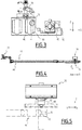
- a railway line segment 10 seen from above is represented on figure 1 .
- the railway line segment 10 comprises a main branch 12, two auxiliary branches 14 and 16, a switch 18 and an apparatus 20 for operating the switch 18.
- the switch 18 enables to determine the track followed by a train, either the main branch 12 and the first auxiliary branch 16 or the main branch 12 and the second auxiliary branch 16.
- a switch 18 is a mechanical installation enabling railway trains to be guided from one track to another, such as at a railway junction or where a spur or siding branches off.
- the switch 18 consists of the pair of linked tapering rails, known as points (switch rails or point blades), lying between the diverging outer rails (the stock rails). These points can be moved laterally into one of two positions to direct a train coming from the point blades toward the straight path or the diverging path. A train moving from the narrow end toward the point blades (i.e. it will be directed to one of the two paths depending on the position of the points) is said to be executing a facing-point movement.
- a switch 18 generally has a straight "through" track (such as the main-line) and a diverging route. The handedness of the installation is described by the side that the diverging track leaves. Right-hand switches have a diverging path to the right of the straight track, when coming from the point blades, and a left-handed switch has the diverging track leaving to the opposite side.
- both tracks may curve, one to the left and one to the right (such as for a wye switch 18), or both tracks may curve, with differing radii, while still in the same direction.
- the switch 18 is adapted to move the points from a starting thrown position to the opposing thrown position.
- the track followed by the train corresponds to the displacement direction, labeled X on figure 1 .
- the transverse direction is the direction which is perpendicular to the displacement direction X and which is in the plane of the railway line segment 10. This transverse direction is labeled Y on figure 1 .
- the vertical direction labeled Z on figure 1 , is perpendicular to the displacement direction X and to the transverse direction Y.
- This movement is orientated upwards while when a movement along the vertical direction Z enables to be closer to the ground, this movement is orientated downwards.
- the switch 18 is adapted to displace blades 22 from a first position to a second position. In the first position, the train follows the main branch 12 and the first auxiliary branch 14 while in the second position, the train follows the main branch 12 and the second auxiliary branch 16.
- the displacement of the blades 22 is carried out along the transverse direction Y.
- the blades 22 are so displaced from one to the other in both position, the first position being such that one blade 22 strikes against one rail and the other is at a distance from the adjacent rail and the opposite for the second position.
- the apparatus 20 is adapted to operate the switch 18.
- the apparatus 20 is often named a "switch machine”. This wording will be used in the remainder of the specification.
- the switch machine 20 comprises a casing 24, a motor 26, a transmitting device 28, a transforming device 30, a coupling device, a detecting device and a locking device 36.
- the casing 24, also named box, comprises several walls 38 which delimitate an inner space 40.
- the locking device 36 is partly integrated in the inner space 40.
- the transmitting device 28 and the coupling device are outside of the casing 24 while the transforming device 30 and the detecting device are inside the casing 24.
- the motor 26 is an actuating motor adapted to produce a motion.
- the motor 26 is producing a rotational motion.
- the motor 26 is a three-phase asynchronous motor.
- the transmitting device 28 and the transforming device 30 cooperate so as to ensure that the motion produced by the motor 26 be converted in a rectilinear motion.
- the transmitting and transforming devices 28 and 30 are adapted to convert the rotation motion of the motor 26 in a linear motion and to convey the linear motion towards the blades 22.
- the transmitting device 28 and the transforming device 30 are switching rods 42.
- the transmitting device 28 and the transforming device 30 are more than two switching rods 42.
- Each switching rod 42 is connected to a respective blade 22 for transmitting the displacement stroke to the blade 22.
- each switching rod 42 extends along the transverse direction Y.
- the coupling device is adapted to couple both transmitting device 28 and transforming device 30 to the points.
- the points are, for instance, bars or tie or combinations of bars and tie rods.
- the coupling device is dynamically connected to the output of both transmitting device 28 and transforming device 30 on one side and to the corresponding switch point on the other side.
- the detecting device is adapted to detect the position of the blade 22.
- the detecting device comprises several detection rods 44 and a key 46.
- the blades 22 are connected to the detection rods 44.
- Each detection rod 44 is adapted to transmit the displacement stroke.
- Each detection rod 44 extends along the transverse direction Y.
- Each detection rod 44 comprises at its end a shaped surface 48 with slots or indentions 50.
- the detection rods 44 mechanically connect the blades 22 with the locking device 36.
- the key 46 has the form of a cursor with a tooth 52.
- the key 46 is adapted to cooperate with a respective slot or indention 50 of one of the detection rod 44 via the tooth 52.
- This cooperation is such that the key 46 can be displaced between an engaged position and a disengaged position.
- the key 46 is engaged in the slot or indention 50.
- the key 46 is further adapted to be displaced along the displacement direction Y.
- the key 46 is a sliding key.
- the key 46 is displaced from one to the other of the said two positions by the driving actuators through a mechanical link such as a cam provided on one or both switching rods 42 and cooperating with a complementary cam surface on the key 46.
- the locking device 36 is adapted to lock the point in the thrown position.
- the locking device 36 is automatically releasable when the device is actuated to move the points from a starting thrown position to the opposing thrown position.
- locking device 36 is driven into the released condition by the translational motion of the coupling device.
- the locking device 36 is known in the special railroad jargon as "switch point locks”.
- the locking device 36 is a blade 22 locking mechanism for blocking the blades 22 in one of the two positions described before.
- the locking device 36 comprises a lever 54, a pusher 56, an axial guide 58, a slider 60, a pin 62, a breakable pin 64, the electric contacts 66 and the spring 68.
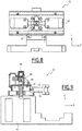
- Breakable pin 64 can notably be seen in figures 6 and 7 .
- the electric contacts 66 are notably represented on figure 8 .
- the lever 54 is a driving lever.
- the lever 54 comprises a lever pin 70 and a slot 72.
- the lever pin 70 is mounted rotatably around an axis passing through an intermediate point between two ends of the said lever pin 70.
- lever pin 70 The opposite free end of the lever pin 70 is intended for cooperating with the pusher 56.
- the axial guide 58 is delimitated by a wall.
- the pin 62 is a retaining pin. This notably means that this is an element of a key retaining mechanism.
- the key 46 is subjected to the key retaining mechanism which prevents the key 46 from being able to be displaced by means of the pin 62.
- the pin 62 is formed by two parts which are a lower pin 82 and upper pin 84.
- the pin 62 extends along the vertical direction Z.
- the pin 62 is oriented perpendicularly to the slider 60 and perpendicularly to a face of the key 46.
- the lower pin 82 is mounted in the slider 60
- the upper pin 84 is mounted in the axial guide 58.
- the lower pin 82 and the upper pin 84 are connected together outside the slider 60 by a breakable pin 64.
- the upper pin 84 has a distal end which is opposite to the lower pin 82.
- the upper pin 84 part bears in a laterally cantilevered position a cam 86 driving two counterposed electrical contacts.
- the electrical contacts are adapted to be commutated by the cam 86 during axial displacement of the pin 62.
- the electric contacts 66 are adapted for generating control signal for signaling the condition of locked or unlocked blades 22.
- the upper pin 84 also bears at least one lateral element which engages the slot 72 at one end of the lever pin 70.
- the lateral element is, for instance, a radial lateral pin.
- the lateral element is two lateral radial and diametric opposite pins.
- the spring 68 is provided between the end of the upper pin 84 and wall of the axial guide 58.
- the spring 68 is adapted to urge the upper pin 84 and the lower pin 82 against a face of the key 46.
- the elements of the locking device 36 are shared between a first unit 90 and a second unit 92.
- the first unit 90 is in in the inner space 40 of the casing 24.
- the second unit 92 is a separate unit.
- the second unit 92 can be dismounted from the casing 24.
- the second unit 92 comprises at least a mechanical fuse 94, a mechanical link 96 and the electric contacts 66.
- This fuse is a structurally weakened retainer pin 62 or other kind of mechanical link 96 between the mechanical elements of the locking mechanism of the blade 22 which are broken in case of a trailing event by the force exerted on the blade 22.
- the fuse is a breakable pin 64.
- the mechanical link 96 is a link to the actuators for controlling activation and deactivation.
- the mechanical link 96 of the locking device 36 comprises only a transmission by contact of a pusher 56 driven by the actuator chain with a lever 54 of the locking mechanism, which causes the locking device 36 to be commutated in the active or inactive condition.
- the mechanical link 96 is a lever 54 and a pusher 56 Lever 54 and pusher 56 have a predefined spatial relative position which allows the pusher 56 to act by contact on the lever 54 for activating/deactivating the locking means.
- the lever 54 When the mechanical fuse 94 is broken, the lever 54 is displaced in a position in which it does not anymore cooperate with the pusher 56 and at the same time a first control signal is emitted. So if a trailing has occurred the control on the switch 18 is irreversibly lost and an intervention on site is requested.
- the first control signal corresponds to the unlocked state.
- the second unit 92 of the locking device 36 comprises the lever 54, the pusher 56, the axial guide 58, the slider 60, the upper pin 84, the breakable pin 64, the electric contacts 66 and the spring 68.
- the first unit 90 comprises the lower pin 82.
- Figure 9 illustrates the operating condition during displacement of the blades 22.
- the pusher 56 acts on the lever 54. This results in a displacement of the pin 62 against the spring 68.
- the key 46 is then free to slide towards the disengaged position.
- the lower pin 82 is driven outside the upper slot 72 in the key 46.
- the cam 86 commutates the electric contact in a position generating a second control signal corresponding to the locked state.
- Figure 10 illustrates the operating condition when the displacement stroke has ended.
- the pusher 56 is displaced back and the lever 54 lowers so that the pin 62 comes to a position in which the lower pin 82 part engages the slot 72 in the key 46.
- the key 46 is then prevented from sliding and the detection rod 44 is also locked.
- the cam 86 reaches a position in which the first control signal is emitted.
- the lever 54 is driven upwardly by the upper pin 84 in a spatial position in which the lever 54 cannot anymore cooperate with the pusher 56.
- the control of the contact is irreversibly lost.
- the mechanical fuse 94 which is broken by a mechanical action exercised on the blades 22 during a trailing event, when the force exercised on the blade 22 exceeds a certain value.
- the breaking of the mechanical fuse 94 which is a weakened point or element of a mechanical locking mechanism, the blades 22 are free to travel from to the other position and the electric contacts 66 are irreversibly commutated for generating the unlocked control signal.
- the second unit 92 can be separated from the switch 18 machine and substituted by another one.
- Such configuration of the locking device in two units 90 and 92 enables to recover of the operation of the apparatus 20 in a very rapid way.
- the reconditioning of the second unit 92 by providing an integer mechanical fuse 94 can be carried out on a remote site.
- the apparatus 20 has three operating configuration which enables to detect that the second unit 92 is to be replaced in an easier way with comparison with the prior art. Indeed, the detecting that the second unit 92 should be replaced is carried out in a manual way in the prior art.
Landscapes
- Engineering & Computer Science (AREA)
- Mechanical Engineering (AREA)
- Architecture (AREA)
- Civil Engineering (AREA)
- Structural Engineering (AREA)
- Train Traffic Observation, Control, And Security (AREA)
- Switch Cases, Indication, And Locking (AREA)
Priority Applications (3)
| Application Number | Priority Date | Filing Date | Title |
|---|---|---|---|
| EP15186911.2A EP3147174B1 (en) | 2015-09-25 | 2015-09-25 | Apparatus for operating a switch of a railway track and associated switch |
| PL15186911T PL3147174T3 (pl) | 2015-09-25 | 2015-09-25 | Urządzenie do obsługi zwrotnicy toru kolejowego i powiązana z nim zwrotnica |
| BR102016021914-0A BR102016021914B1 (pt) | 2015-09-25 | 2016-09-23 | Aparelho para operar um comutador de uma via férrea e comutador de uma via férrea |
Applications Claiming Priority (1)
| Application Number | Priority Date | Filing Date | Title |
|---|---|---|---|
| EP15186911.2A EP3147174B1 (en) | 2015-09-25 | 2015-09-25 | Apparatus for operating a switch of a railway track and associated switch |
Publications (2)
| Publication Number | Publication Date |
|---|---|
| EP3147174A1 EP3147174A1 (en) | 2017-03-29 |
| EP3147174B1 true EP3147174B1 (en) | 2019-12-11 |
Family
ID=54238272
Family Applications (1)
| Application Number | Title | Priority Date | Filing Date |
|---|---|---|---|
| EP15186911.2A Active EP3147174B1 (en) | 2015-09-25 | 2015-09-25 | Apparatus for operating a switch of a railway track and associated switch |
Country Status (3)
| Country | Link |
|---|---|
| EP (1) | EP3147174B1 (pl) |
| BR (1) | BR102016021914B1 (pl) |
| PL (1) | PL3147174T3 (pl) |
Cited By (1)
| Publication number | Priority date | Publication date | Assignee | Title |
|---|---|---|---|---|
| RU201138U1 (ru) * | 2020-08-18 | 2020-11-30 | Евгения Александровна Ершова | Нож контактный колодки автопереключателя |
Family Cites Families (2)
| Publication number | Priority date | Publication date | Assignee | Title |
|---|---|---|---|---|
| AT393250B (de) * | 1990-05-14 | 1991-09-10 | Alcatel Austria Ag | Weichenantrieb |
| DE102013009116B4 (de) * | 2012-06-13 | 2026-03-05 | Pintsch Wolber Gmbh | Weichenantrieb für ein Eisenbahngleis |
-
2015
- 2015-09-25 PL PL15186911T patent/PL3147174T3/pl unknown
- 2015-09-25 EP EP15186911.2A patent/EP3147174B1/en active Active
-
2016
- 2016-09-23 BR BR102016021914-0A patent/BR102016021914B1/pt active IP Right Grant
Non-Patent Citations (1)
| Title |
|---|
| None * |
Cited By (1)
| Publication number | Priority date | Publication date | Assignee | Title |
|---|---|---|---|---|
| RU201138U1 (ru) * | 2020-08-18 | 2020-11-30 | Евгения Александровна Ершова | Нож контактный колодки автопереключателя |
Also Published As
| Publication number | Publication date |
|---|---|
| EP3147174A1 (en) | 2017-03-29 |
| PL3147174T3 (pl) | 2020-05-18 |
| BR102016021914A2 (pt) | 2017-04-04 |
| BR102016021914B1 (pt) | 2022-10-11 |
Similar Documents
| Publication | Publication Date | Title |
|---|---|---|
| EP1594732B1 (en) | Switch machine for railway and tramway switches | |
| CN203833409U (zh) | 一种防止轿厢意外移动保护装置 | |
| EP3092340B1 (en) | Railway points, railway points operating apparatus and railway track crossing | |
| CN101841134A (zh) | 电开关装置 | |
| US12104331B2 (en) | Saborage-resistant switch device for moving railroad switch points | |
| EP3147174A1 (en) | Apparatus for operating a switch of a railway track and associated method and switch | |
| HK1229775A (en) | Apparatus for operating a switch of a railway track and associated method and switch | |
| HK1229775A1 (en) | Apparatus for operating a switch of a railway track and associated method and switch | |
| EP3473520A1 (en) | Safety device for switch machines | |
| EP1219521B1 (en) | Switch machine for railroad switches or the like, having a trailing resistant device for opposing trailing of the switch points | |
| CN102723222A (zh) | 固定式高压开关柜连锁机构 | |
| EP1752354B1 (en) | Point drive system | |
| KR101038199B1 (ko) | 선로전환기용 브레이크 | |
| US764043A (en) | Railway switching apparatus. | |
| RU2826930C1 (ru) | Устройство двухконтурного комбинированного замыкания и двойного контроля положения остряков стрелочных переводов для скоростных железных дорог | |
| US443149A (en) | Railway-switch-operating system | |
| Bemment et al. | Redundantly engineered points (REPOINT) for enhanced reliability and capacity of railway track switching | |
| US897401A (en) | Electric signaling system. | |
| GB2516707A (en) | Railway points operating apparatus | |
| US575908A (en) | Vania | |
| US1961855A (en) | Railway traffic controlling system | |
| US2305954A (en) | Locking means for electric motor mechanism | |
| AT86110B (de) | Zugdeckungseinrichtung für Elektrohängebahnen. | |
| US830472A (en) | Controller for automatic railways. | |
| US726361A (en) | Electrical switch-lock. |
Legal Events
| Date | Code | Title | Description |
|---|---|---|---|
| PUAI | Public reference made under article 153(3) epc to a published international application that has entered the european phase |
Free format text: ORIGINAL CODE: 0009012 |
|
| STAA | Information on the status of an ep patent application or granted ep patent |
Free format text: STATUS: THE APPLICATION HAS BEEN PUBLISHED |
|
| STAA | Information on the status of an ep patent application or granted ep patent |
Free format text: STATUS: REQUEST FOR EXAMINATION WAS MADE |
|
| AK | Designated contracting states |
Kind code of ref document: A1 Designated state(s): AL AT BE BG CH CY CZ DE DK EE ES FI FR GB GR HR HU IE IS IT LI LT LU LV MC MK MT NL NO PL PT RO RS SE SI SK SM TR |
|
| AX | Request for extension of the european patent |
Extension state: BA ME |
|
| 17P | Request for examination filed |
Effective date: 20170310 |
|
| RBV | Designated contracting states (corrected) |
Designated state(s): AL AT BE BG CH CY CZ DE DK EE ES FI FR GB GR HR HU IE IS IT LI LT LU LV MC MK MT NL NO PL PT RO RS SE SI SK SM TR |
|
| STAA | Information on the status of an ep patent application or granted ep patent |
Free format text: STATUS: EXAMINATION IS IN PROGRESS |
|
| 17Q | First examination report despatched |
Effective date: 20170821 |
|
| REG | Reference to a national code |
Ref country code: HK Ref legal event code: DE Ref document number: 1229775 Country of ref document: HK |
|
| GRAP | Despatch of communication of intention to grant a patent |
Free format text: ORIGINAL CODE: EPIDOSNIGR1 |
|
| STAA | Information on the status of an ep patent application or granted ep patent |
Free format text: STATUS: GRANT OF PATENT IS INTENDED |
|
| INTG | Intention to grant announced |
Effective date: 20190715 |
|
| GRAS | Grant fee paid |
Free format text: ORIGINAL CODE: EPIDOSNIGR3 |
|
| GRAA | (expected) grant |
Free format text: ORIGINAL CODE: 0009210 |
|
| STAA | Information on the status of an ep patent application or granted ep patent |
Free format text: STATUS: THE PATENT HAS BEEN GRANTED |
|
| AK | Designated contracting states |
Kind code of ref document: B1 Designated state(s): AL AT BE BG CH CY CZ DE DK EE ES FI FR GB GR HR HU IE IS IT LI LT LU LV MC MK MT NL NO PL PT RO RS SE SI SK SM TR |
|
| REG | Reference to a national code |
Ref country code: GB Ref legal event code: FG4D |
|
| REG | Reference to a national code |
Ref country code: CH Ref legal event code: EP |
|
| REG | Reference to a national code |
Ref country code: AT Ref legal event code: REF Ref document number: 1211913 Country of ref document: AT Kind code of ref document: T Effective date: 20191215 |
|
| REG | Reference to a national code |
Ref country code: DE Ref legal event code: R096 Ref document number: 602015043351 Country of ref document: DE |
|
| REG | Reference to a national code |
Ref country code: IE Ref legal event code: FG4D |
|
| REG | Reference to a national code |
Ref country code: RO Ref legal event code: EPE |
|
| REG | Reference to a national code |
Ref country code: NL Ref legal event code: MP Effective date: 20191211 |
|
| REG | Reference to a national code |
Ref country code: LT Ref legal event code: MG4D |
|
| PG25 | Lapsed in a contracting state [announced via postgrant information from national office to epo] |
Ref country code: LT Free format text: LAPSE BECAUSE OF FAILURE TO SUBMIT A TRANSLATION OF THE DESCRIPTION OR TO PAY THE FEE WITHIN THE PRESCRIBED TIME-LIMIT Effective date: 20191211 Ref country code: BG Free format text: LAPSE BECAUSE OF FAILURE TO SUBMIT A TRANSLATION OF THE DESCRIPTION OR TO PAY THE FEE WITHIN THE PRESCRIBED TIME-LIMIT Effective date: 20200311 Ref country code: FI Free format text: LAPSE BECAUSE OF FAILURE TO SUBMIT A TRANSLATION OF THE DESCRIPTION OR TO PAY THE FEE WITHIN THE PRESCRIBED TIME-LIMIT Effective date: 20191211 Ref country code: SE Free format text: LAPSE BECAUSE OF FAILURE TO SUBMIT A TRANSLATION OF THE DESCRIPTION OR TO PAY THE FEE WITHIN THE PRESCRIBED TIME-LIMIT Effective date: 20191211 Ref country code: LV Free format text: LAPSE BECAUSE OF FAILURE TO SUBMIT A TRANSLATION OF THE DESCRIPTION OR TO PAY THE FEE WITHIN THE PRESCRIBED TIME-LIMIT Effective date: 20191211 Ref country code: NO Free format text: LAPSE BECAUSE OF FAILURE TO SUBMIT A TRANSLATION OF THE DESCRIPTION OR TO PAY THE FEE WITHIN THE PRESCRIBED TIME-LIMIT Effective date: 20200311 |
|
| REG | Reference to a national code |
Ref country code: GR Ref legal event code: EP Ref document number: 20200400218 Country of ref document: GR Effective date: 20200511 |
|
| PG25 | Lapsed in a contracting state [announced via postgrant information from national office to epo] |
Ref country code: HR Free format text: LAPSE BECAUSE OF FAILURE TO SUBMIT A TRANSLATION OF THE DESCRIPTION OR TO PAY THE FEE WITHIN THE PRESCRIBED TIME-LIMIT Effective date: 20191211 Ref country code: RS Free format text: LAPSE BECAUSE OF FAILURE TO SUBMIT A TRANSLATION OF THE DESCRIPTION OR TO PAY THE FEE WITHIN THE PRESCRIBED TIME-LIMIT Effective date: 20191211 |
|
| PG25 | Lapsed in a contracting state [announced via postgrant information from national office to epo] |
Ref country code: AL Free format text: LAPSE BECAUSE OF FAILURE TO SUBMIT A TRANSLATION OF THE DESCRIPTION OR TO PAY THE FEE WITHIN THE PRESCRIBED TIME-LIMIT Effective date: 20191211 |
|
| PG25 | Lapsed in a contracting state [announced via postgrant information from national office to epo] |
Ref country code: ES Free format text: LAPSE BECAUSE OF FAILURE TO SUBMIT A TRANSLATION OF THE DESCRIPTION OR TO PAY THE FEE WITHIN THE PRESCRIBED TIME-LIMIT Effective date: 20191211 Ref country code: NL Free format text: LAPSE BECAUSE OF FAILURE TO SUBMIT A TRANSLATION OF THE DESCRIPTION OR TO PAY THE FEE WITHIN THE PRESCRIBED TIME-LIMIT Effective date: 20191211 Ref country code: CZ Free format text: LAPSE BECAUSE OF FAILURE TO SUBMIT A TRANSLATION OF THE DESCRIPTION OR TO PAY THE FEE WITHIN THE PRESCRIBED TIME-LIMIT Effective date: 20191211 Ref country code: EE Free format text: LAPSE BECAUSE OF FAILURE TO SUBMIT A TRANSLATION OF THE DESCRIPTION OR TO PAY THE FEE WITHIN THE PRESCRIBED TIME-LIMIT Effective date: 20191211 Ref country code: PT Free format text: LAPSE BECAUSE OF FAILURE TO SUBMIT A TRANSLATION OF THE DESCRIPTION OR TO PAY THE FEE WITHIN THE PRESCRIBED TIME-LIMIT Effective date: 20200506 |
|
| PG25 | Lapsed in a contracting state [announced via postgrant information from national office to epo] |
Ref country code: IS Free format text: LAPSE BECAUSE OF FAILURE TO SUBMIT A TRANSLATION OF THE DESCRIPTION OR TO PAY THE FEE WITHIN THE PRESCRIBED TIME-LIMIT Effective date: 20200411 Ref country code: SK Free format text: LAPSE BECAUSE OF FAILURE TO SUBMIT A TRANSLATION OF THE DESCRIPTION OR TO PAY THE FEE WITHIN THE PRESCRIBED TIME-LIMIT Effective date: 20191211 Ref country code: SM Free format text: LAPSE BECAUSE OF FAILURE TO SUBMIT A TRANSLATION OF THE DESCRIPTION OR TO PAY THE FEE WITHIN THE PRESCRIBED TIME-LIMIT Effective date: 20191211 |
|
| REG | Reference to a national code |
Ref country code: DE Ref legal event code: R097 Ref document number: 602015043351 Country of ref document: DE |
|
| REG | Reference to a national code |
Ref country code: AT Ref legal event code: MK05 Ref document number: 1211913 Country of ref document: AT Kind code of ref document: T Effective date: 20191211 |
|
| PLBE | No opposition filed within time limit |
Free format text: ORIGINAL CODE: 0009261 |
|
| STAA | Information on the status of an ep patent application or granted ep patent |
Free format text: STATUS: NO OPPOSITION FILED WITHIN TIME LIMIT |
|
| PG25 | Lapsed in a contracting state [announced via postgrant information from national office to epo] |
Ref country code: DK Free format text: LAPSE BECAUSE OF FAILURE TO SUBMIT A TRANSLATION OF THE DESCRIPTION OR TO PAY THE FEE WITHIN THE PRESCRIBED TIME-LIMIT Effective date: 20191211 |
|
| 26N | No opposition filed |
Effective date: 20200914 |
|
| PG25 | Lapsed in a contracting state [announced via postgrant information from national office to epo] |
Ref country code: AT Free format text: LAPSE BECAUSE OF FAILURE TO SUBMIT A TRANSLATION OF THE DESCRIPTION OR TO PAY THE FEE WITHIN THE PRESCRIBED TIME-LIMIT Effective date: 20191211 Ref country code: SI Free format text: LAPSE BECAUSE OF FAILURE TO SUBMIT A TRANSLATION OF THE DESCRIPTION OR TO PAY THE FEE WITHIN THE PRESCRIBED TIME-LIMIT Effective date: 20191211 |
|
| REG | Reference to a national code |
Ref country code: DE Ref legal event code: R119 Ref document number: 602015043351 Country of ref document: DE |
|
| PG25 | Lapsed in a contracting state [announced via postgrant information from national office to epo] |
Ref country code: MC Free format text: LAPSE BECAUSE OF FAILURE TO SUBMIT A TRANSLATION OF THE DESCRIPTION OR TO PAY THE FEE WITHIN THE PRESCRIBED TIME-LIMIT Effective date: 20191211 |
|
| REG | Reference to a national code |
Ref country code: CH Ref legal event code: PL |
|
| GBPC | Gb: european patent ceased through non-payment of renewal fee |
Effective date: 20200925 |
|
| REG | Reference to a national code |
Ref country code: BE Ref legal event code: MM Effective date: 20200930 |
|
| PG25 | Lapsed in a contracting state [announced via postgrant information from national office to epo] |
Ref country code: LU Free format text: LAPSE BECAUSE OF NON-PAYMENT OF DUE FEES Effective date: 20200925 |
|
| PG25 | Lapsed in a contracting state [announced via postgrant information from national office to epo] |
Ref country code: DE Free format text: LAPSE BECAUSE OF NON-PAYMENT OF DUE FEES Effective date: 20210401 Ref country code: FR Free format text: LAPSE BECAUSE OF NON-PAYMENT OF DUE FEES Effective date: 20200930 |
|
| PG25 | Lapsed in a contracting state [announced via postgrant information from national office to epo] |
Ref country code: GB Free format text: LAPSE BECAUSE OF NON-PAYMENT OF DUE FEES Effective date: 20200925 Ref country code: IE Free format text: LAPSE BECAUSE OF NON-PAYMENT OF DUE FEES Effective date: 20200925 Ref country code: LI Free format text: LAPSE BECAUSE OF NON-PAYMENT OF DUE FEES Effective date: 20200930 Ref country code: CH Free format text: LAPSE BECAUSE OF NON-PAYMENT OF DUE FEES Effective date: 20200930 Ref country code: BE Free format text: LAPSE BECAUSE OF NON-PAYMENT OF DUE FEES Effective date: 20200930 |
|
| PG25 | Lapsed in a contracting state [announced via postgrant information from national office to epo] |
Ref country code: TR Free format text: LAPSE BECAUSE OF FAILURE TO SUBMIT A TRANSLATION OF THE DESCRIPTION OR TO PAY THE FEE WITHIN THE PRESCRIBED TIME-LIMIT Effective date: 20191211 Ref country code: MT Free format text: LAPSE BECAUSE OF FAILURE TO SUBMIT A TRANSLATION OF THE DESCRIPTION OR TO PAY THE FEE WITHIN THE PRESCRIBED TIME-LIMIT Effective date: 20191211 Ref country code: CY Free format text: LAPSE BECAUSE OF FAILURE TO SUBMIT A TRANSLATION OF THE DESCRIPTION OR TO PAY THE FEE WITHIN THE PRESCRIBED TIME-LIMIT Effective date: 20191211 |
|
| PG25 | Lapsed in a contracting state [announced via postgrant information from national office to epo] |
Ref country code: MK Free format text: LAPSE BECAUSE OF FAILURE TO SUBMIT A TRANSLATION OF THE DESCRIPTION OR TO PAY THE FEE WITHIN THE PRESCRIBED TIME-LIMIT Effective date: 20191211 |
|
| P01 | Opt-out of the competence of the unified patent court (upc) registered |
Effective date: 20231124 |
|
| REG | Reference to a national code |
Ref country code: HK Ref legal event code: WD Ref document number: 1229775 Country of ref document: HK |
|
| PGFP | Annual fee paid to national office [announced via postgrant information from national office to epo] |
Ref country code: GR Payment date: 20250922 Year of fee payment: 11 |
|
| PGFP | Annual fee paid to national office [announced via postgrant information from national office to epo] |
Ref country code: PL Payment date: 20250911 Year of fee payment: 11 Ref country code: IT Payment date: 20250923 Year of fee payment: 11 |
|
| PGFP | Annual fee paid to national office [announced via postgrant information from national office to epo] |
Ref country code: RO Payment date: 20250916 Year of fee payment: 11 |