EP3147163A1 - Vehicular energy absorption structure - Google Patents
Vehicular energy absorption structure Download PDFInfo
- Publication number
- EP3147163A1 EP3147163A1 EP16183292.8A EP16183292A EP3147163A1 EP 3147163 A1 EP3147163 A1 EP 3147163A1 EP 16183292 A EP16183292 A EP 16183292A EP 3147163 A1 EP3147163 A1 EP 3147163A1
- Authority
- EP
- European Patent Office
- Prior art keywords
- energy absorption
- wall
- absorption body
- abutting
- peripheral wall
- Prior art date
- Legal status (The legal status is an assumption and is not a legal conclusion. Google has not performed a legal analysis and makes no representation as to the accuracy of the status listed.)
- Granted
Links
- 238000010521 absorption reaction Methods 0.000 title claims abstract description 179
- 239000000835 fiber Substances 0.000 claims abstract description 10
- 239000011347 resin Substances 0.000 claims abstract description 10
- 229920005989 resin Polymers 0.000 claims abstract description 10
- 230000002093 peripheral effect Effects 0.000 claims description 68
- 230000008878 coupling Effects 0.000 claims description 16
- 238000010168 coupling process Methods 0.000 claims description 16
- 238000005859 coupling reaction Methods 0.000 claims description 16
- 230000002787 reinforcement Effects 0.000 description 38
- 238000010586 diagram Methods 0.000 description 4
- 230000000052 comparative effect Effects 0.000 description 3
- 230000000694 effects Effects 0.000 description 3
- 238000004026 adhesive bonding Methods 0.000 description 2
- 230000000750 progressive effect Effects 0.000 description 2
- 238000003466 welding Methods 0.000 description 2
- 230000006835 compression Effects 0.000 description 1
- 238000007906 compression Methods 0.000 description 1
- 238000005516 engineering process Methods 0.000 description 1
- 230000001771 impaired effect Effects 0.000 description 1
Images



Classifications
-
- B—PERFORMING OPERATIONS; TRANSPORTING
- B60—VEHICLES IN GENERAL
- B60R—VEHICLES, VEHICLE FITTINGS, OR VEHICLE PARTS, NOT OTHERWISE PROVIDED FOR
- B60R19/00—Wheel guards; Radiator guards, e.g. grilles; Obstruction removers; Fittings damping bouncing force in collisions
- B60R19/02—Bumpers, i.e. impact receiving or absorbing members for protecting vehicles or fending off blows from other vehicles or objects
- B60R19/24—Arrangements for mounting bumpers on vehicles
- B60R19/26—Arrangements for mounting bumpers on vehicles comprising yieldable mounting means
- B60R19/34—Arrangements for mounting bumpers on vehicles comprising yieldable mounting means destroyed upon impact, e.g. one-shot type
-
- B—PERFORMING OPERATIONS; TRANSPORTING
- B60—VEHICLES IN GENERAL
- B60R—VEHICLES, VEHICLE FITTINGS, OR VEHICLE PARTS, NOT OTHERWISE PROVIDED FOR
- B60R19/00—Wheel guards; Radiator guards, e.g. grilles; Obstruction removers; Fittings damping bouncing force in collisions
- B60R19/02—Bumpers, i.e. impact receiving or absorbing members for protecting vehicles or fending off blows from other vehicles or objects
- B60R19/03—Bumpers, i.e. impact receiving or absorbing members for protecting vehicles or fending off blows from other vehicles or objects characterised by material, e.g. composite
-
- B—PERFORMING OPERATIONS; TRANSPORTING
- B60—VEHICLES IN GENERAL
- B60R—VEHICLES, VEHICLE FITTINGS, OR VEHICLE PARTS, NOT OTHERWISE PROVIDED FOR
- B60R19/00—Wheel guards; Radiator guards, e.g. grilles; Obstruction removers; Fittings damping bouncing force in collisions
- B60R19/02—Bumpers, i.e. impact receiving or absorbing members for protecting vehicles or fending off blows from other vehicles or objects
- B60R19/04—Bumpers, i.e. impact receiving or absorbing members for protecting vehicles or fending off blows from other vehicles or objects formed from more than one section in a side-by-side arrangement
-
- F—MECHANICAL ENGINEERING; LIGHTING; HEATING; WEAPONS; BLASTING
- F16—ENGINEERING ELEMENTS AND UNITS; GENERAL MEASURES FOR PRODUCING AND MAINTAINING EFFECTIVE FUNCTIONING OF MACHINES OR INSTALLATIONS; THERMAL INSULATION IN GENERAL
- F16F—SPRINGS; SHOCK-ABSORBERS; MEANS FOR DAMPING VIBRATION
- F16F7/00—Vibration-dampers; Shock-absorbers
-
- F—MECHANICAL ENGINEERING; LIGHTING; HEATING; WEAPONS; BLASTING
- F16—ENGINEERING ELEMENTS AND UNITS; GENERAL MEASURES FOR PRODUCING AND MAINTAINING EFFECTIVE FUNCTIONING OF MACHINES OR INSTALLATIONS; THERMAL INSULATION IN GENERAL
- F16F—SPRINGS; SHOCK-ABSORBERS; MEANS FOR DAMPING VIBRATION
- F16F7/00—Vibration-dampers; Shock-absorbers
- F16F7/12—Vibration-dampers; Shock-absorbers using plastic deformation of members
-
- F—MECHANICAL ENGINEERING; LIGHTING; HEATING; WEAPONS; BLASTING
- F16—ENGINEERING ELEMENTS AND UNITS; GENERAL MEASURES FOR PRODUCING AND MAINTAINING EFFECTIVE FUNCTIONING OF MACHINES OR INSTALLATIONS; THERMAL INSULATION IN GENERAL
- F16F—SPRINGS; SHOCK-ABSORBERS; MEANS FOR DAMPING VIBRATION
- F16F7/00—Vibration-dampers; Shock-absorbers
- F16F7/12—Vibration-dampers; Shock-absorbers using plastic deformation of members
- F16F7/124—Vibration-dampers; Shock-absorbers using plastic deformation of members characterised by their special construction from fibre-reinforced plastics
-
- F—MECHANICAL ENGINEERING; LIGHTING; HEATING; WEAPONS; BLASTING
- F16—ENGINEERING ELEMENTS AND UNITS; GENERAL MEASURES FOR PRODUCING AND MAINTAINING EFFECTIVE FUNCTIONING OF MACHINES OR INSTALLATIONS; THERMAL INSULATION IN GENERAL
- F16F—SPRINGS; SHOCK-ABSORBERS; MEANS FOR DAMPING VIBRATION
- F16F7/00—Vibration-dampers; Shock-absorbers
- F16F7/12—Vibration-dampers; Shock-absorbers using plastic deformation of members
- F16F7/128—Vibration-dampers; Shock-absorbers using plastic deformation of members characterised by the members, e.g. a flat strap, yielding through stretching, pulling apart
-
- F—MECHANICAL ENGINEERING; LIGHTING; HEATING; WEAPONS; BLASTING
- F16—ENGINEERING ELEMENTS AND UNITS; GENERAL MEASURES FOR PRODUCING AND MAINTAINING EFFECTIVE FUNCTIONING OF MACHINES OR INSTALLATIONS; THERMAL INSULATION IN GENERAL
- F16F—SPRINGS; SHOCK-ABSORBERS; MEANS FOR DAMPING VIBRATION
- F16F2224/00—Materials; Material properties
- F16F2224/02—Materials; Material properties solids
- F16F2224/0241—Fibre-reinforced plastics [FRP]
Definitions
- the embodiments discussed herein are related to an energy absorption structure for a vehicle.
- JP-A No. 2005-233263 describes a vehicular energy absorption structure including a tubular shaped crash box (energy absorption body) formed from fiber reinforced resin, and a pressing member (guide member) provided with a protrusion that abuts the inside of the crash box.
- a structure that is, such as in the above conventional technology, provided with a projection (guide section) that abuts the inside of the crash box, prevents positional misalignment of a crash box with respect to bumper reinforcement during a collision of a vehicle.
- the portion of the crash box that is crushed enters between the crash box and the guide section as the crash box is being crushed during a vehicle collision.
- this impedes the progressive deformation of the crash box, leading to concerns regarding a reduction in the amount of energy absorption.
- an object of the present invention is to obtain stable energy absorption characteristics in a vehicular energy absorption structure with a guide section provided internally to an tube shaped energy absorption body formed from fiber reinforced resin.
- a vehicular energy absorption structure is a vehicular energy absorption structure including a tube shaped energy absorption body made from a fiber reinforced resin, an opposing face that is provided facing an axial direction end portion of the energy absorption body, and that, during a vehicle collision, crushes the energy absorption body from the axial direction end portion, and a guide section that projects out from the opposing face and that is disposed at an interior of the energy absorption body, wherein the guide section comprises an abutting section, that is provided so as to be capable of contacting a wall configuring the energy absorption body from an inner side during a vehicle collision, and is separated from the opposing face by an opening in an axial direction of the energy absorption body.
- the vehicular energy absorption structure includes the tube shaped energy absorption body made from a fiber reinforced resin, and the opposing face that is provided facing an axial direction end portion of the energy absorption body. During a vehicle collision, the opposing face crushes the energy absorption body from the axial direction end portion. Collision energy is absorbed thereby.
- the vehicular energy absorption structure also includes the guide section that projects out from the opposing face and that is disposed at the interior of the energy absorption body.
- the guide section includes the abutting section.
- the abutting section is provided so as to be capable of contacting the wall configuring (forming) the energy absorption body from the inner side during a vehicle collision. Positional misalignment of the energy absorption body with respect to the opposing face does thereby not occur during a vehicle collision.
- the abutting section is also separated from the opposing face by the opening in the axial direction of the energy absorption body.
- the guide section is provided with the opening located between the opposing face and the abutting section, in the axial direction.
- This opening is an opening (escape path) enabling communication of the space on the side of the abutting section at the side of the wall forming the energy absorption body, with the space on the side of the abutting section at the opposite side to the wall forming the energy absorption body.
- crushed portions entering into the interior of the energy absorption body are able to escape through these openings, to the space on the side of the abutting section at the opposite side to the wall forming the energy absorption body (to the center side of the energy absorption body). This thereby prevents the crushed portions from becoming jammed between the abutting section and the portions of the wall forming the energy absorption body that have not yet been crushed.
- the energy absorption body when the energy absorption body is crushed from its axial direction end portion during a vehicle collision, crushed portions are generated in the vicinity of the opposing face, i.e. at the axial direction end portion of the energy absorption body.
- the abutting section is separated from the opposing face by an opening in the axial direction of the energy absorption body.
- the opening is accordingly formed in the vicinity of the opposing face.
- a vehicular energy absorption structure according to a second aspect of the present disclosure is the vehicular energy absorption structure according to the first aspect of the present disclosure, wherein the abutting section is an abutting wall that is substantially parallel to the wall configuring the energy absorption body.
- the abutting section which is capable of contacting the wall forming the energy absorption body from the inner side during a vehicle collision, is the wall provided substantially parallel to the wall forming the energy absorption body. Portions of the abutting wall are respectively parallel to corresponding portions of the wall forming the energy absorption body.
- the abutting wall may be coaxial with the wall forming the energy absorption body. A large load is thereby prevented from being locally input to the wall forming the energy absorption body. This thereby prevents the energy absorption body from being broken by contact with the abutting section.
- a vehicular energy absorption structure is the vehicular energy absorption structure according to the second aspect of the present disclosure, wherein the guide section includes a coupling portion that is disposed on an opposite side of the abutting wall from the wall configuring the energy absorption body, and that couples the abutting wall and the opposing face together.
- the guide section includes the coupling portion that couples the abutting wall and the opposing face together. More generally, the coupling portion couples the guide section and the opposing face. This thereby enables the abutting wall to be supported by the coupling portion, and, as a result, facilitates forming of a larger opening between the abutting wall and the opposing face.
- the coupling portion is disposed on the opposite side of the abutting wall from the side of the wall forming the energy absorption body. Thus the crushed portions are accordingly prevented from becoming jammed between the coupling portion and the wall forming the energy absorption body.
- a vehicular energy absorption structure is the vehicular energy absorption structure according to the second aspect of the present disclosure, wherein the abutting wall is a peripheral wall corresponding to an entire periphery of the wall configuring the energy absorption body, the guide section is disposed at an interior of the peripheral wall and includes a coupling portion that couples the peripheral wall and the opposing face together, and the peripheral wall and the opposing face are separated from each other by an opening around an entire periphery of the peripheral wall.
- the abutting wall is a peripheral wall provided corresponding to the entire periphery of the wall forming the energy absorption body.
- the guide section is disposed at the interior of the peripheral wall and includes the coupling portion that couples the peripheral wall and the opposing face together.
- the peripheral wall is accordingly supported by the coupling portion.
- the peripheral wall and the opposing face are separated from each other by an opening around the entire periphery of the peripheral wall. This thereby enables the crushed portions of the energy absorption body to escape into the interior of the peripheral wall around the entire periphery of the energy absorption body. This thereby enables even more stable energy absorption characteristics to be obtained.
- the vehicular energy absorption structure according to the first aspect of the present disclosure enables even more stable energy absorption characteristics to be obtained in a vehicular energy absorption structure provided with a guide section at the interior of a tube shaped energy absorption body made from a fiber reinforced resin.
- arrows FR, the arrows UP, the arrows OUT, and the arrows W applied in each of the drawings respectively indicate a front direction (direction of progression), an up direction, outside in a vehicle width direction, and a vehicle width direction, of a vehicle.
- reference in the following simply to front or rear, left or right, or up or down directions indicates front or rear in a vehicle front-rear direction, left or right in a vehicle left-right direction (vehicle width direction), or up or down in a vehicle up-down direction.
- Fig. 1 is an exploded perspective view illustrating an overall configuration of a vehicle front section structure S.
- the vehicle front section structure S includes a bumper reinforcement 16 that is present extending in the vehicle front end section along a vehicle width direction.
- a pair of left and right guide members 18 are respectively joined to rear faces 16R at a vehicle rear side of the bumper reinforcement 16.
- a pair of left and right crash boxes 14 are respectively joined to portions at the vehicle rear side of the bumper reinforcement 16 corresponding to the guide members 18.
- front side members (not illustrated in the drawings), which are framework members having their length direction along the vehicle front-rear direction, are coaxially jointed to the crash boxes 14.
- the bumper reinforcement 16 has a closed cross-section structure formed with a substantially rectangular shape in cross-section orthogonal to the length direction, and includes an upper face 16U facing upward, a lower face 16L facing downward, a rear face 16R facing rearward, and a front face 16F facing forward.
- the crash boxes 14 are joined to the bumper reinforcement 16 at the vehicle rear side (see Fig. 3 ).
- the crash boxes 14 are provided parallel to each other as a left and right pair.
- the crash boxes 14 are formed from fiber reinforced resin.
- the crash boxes 14 each includes a tube shaped energy absorption body 14A, a front flange 14F provided as a joint portion to a front end of the energy absorption body 14A, and a rear flange 14R provided to a rear end of the energy absorption body 14A.
- the energy absorption body 14A has a tube shape (closed cross-section structure), e.g. of substantially rectangular cross-section, including a top side wall 14T facing upward, a bottom side wall 14B facing downward, an inside wall 14I facing toward a vehicle width direction inside, and an outside wall 140 facing toward a vehicle width direction outside.
- a tube shape e.g. of substantially rectangular cross-section, including a top side wall 14T facing upward, a bottom side wall 14B facing downward, an inside wall 14I facing toward a vehicle width direction inside, and an outside wall 140 facing toward a vehicle width direction outside.
- the front flange 14F is formed extending from a front end of the energy absorption body 14A along an up-down direction, and is joined to the bumper reinforcement 16, in a state in which the upper face 16U and the lower face 16L of the bumper reinforcement 16 are held therein. Adhesive bonding, welding, riveting or the like may, for example, be employed for such joining. More specifically, the front flange 14F includes a front wall 14FF that juts out from the front end of the energy absorption body 14A toward the top and bottom and left and right, an upper wall 14FU that extends out forward from an upper end of the front wall 14FF, and a lower wall 14FL that extends out forward from a lower end of the front wall 14FF.
- the front wall 14FF of the front flange 14F, and the front end of the energy absorption body 14A together abut an attachment plate 20 of each of the guide members 18, described later.
- the upper wall 14FU and the lower wall 14FL are respectively joined to the upper face 16U and the lower face 16L of the bumper reinforcement 16.
- the front flange 14F serving as a joint portion is respectively joined to both upper and lower direction ends of the bumper reinforcement 16.
- Adhesive bonding, welding, riveting or the like may, for example, be employed in such a joining state.
- the front wall 14FF is fastened together with the attachment plate 20 of each of the guide members 18, and the rear face 16R of the bumper reinforcement 16.
- the vehicle front section structure S includes the guide members 18, each serving as a "guide section” and including a peripheral wall 22 and ribs 26.
- the guide members 18 each includes the attachment plate 20 joined to the rear face 16R of the bumper reinforcement 16, and the peripheral wall 22 and the ribs 26 formed projecting out from the attachment plate 20. Namely, the peripheral wall 22 and the ribs 26 of each of the guide members 18 project out from the attachment plate 20 toward the rear. As illustrated in Figs. 3A and 3B , the peripheral wall 22 and the ribs 26 of each of the guide members 18 fit into an interior 24 of the energy absorption body 14A having a closed cross-section structure.
- Each of the guide members 18 is configured to prevent positional misalignment of the energy absorption body 14A with respect to the attachment plate 20 and the bumper reinforcement 16, when joining of the energy absorption body 14A to the bumper reinforcement 16 and the attachment plate 20, through the front flange 14F, has been released (separated).
- each of the guide members 18 is a guide member that guides each front-rear direction portion of the energy absorption body 14A toward an appropriate location on the attachment plate 20 and the bumper reinforcement 16 as the energy absorption body 14A is being broken under compression from the front.
- the guide members 18 each includes, as main parts thereof, the attachment plate 20 that is joined in a superimposed state to the rear face 16R of the bumper reinforcement 16, the peripheral wall 22 that projects out from the attachment plate 20 toward the vehicle rear side, and at least one rib 26, here several ribs 26 that are formed in a shape radiating out from a center of the attachment plate 20 and that reinforce the attachment plate 20 and the peripheral wall 22.
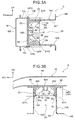
- the attachment plate 20 is configured in a substantially rectangular plate shape. As illustrated in Fig. 3A , the upper end of the attachment plate 20 is substantially aligned with the upper end of the rear face 16R of the bumper reinforcement 16, and the lower end of the attachment plate 20 is substantially aligned with the lower end of the rear face 16R of the bumper reinforcement 16. In a state in which each of the crash boxes 14 is joined to the bumper reinforcement 16, the two up-down direction ends of the energy absorption body 14A are positioned between the two up-down direction ends of the attachment plate 20.
- the upper end of the attachment plate 20 is positioned by an amount ⁇ Ht further toward the vehicle top than the top side wall 14T of the energy absorption body 14A, and the lower end of the attachment plate 20 is positioned by an amount ⁇ Hb further toward the vehicle bottom than the bottom side wall 14B of the energy absorption body 14A.
- a vehicle width direction outside end of the attachment plate 20 is positioned by an amount ⁇ Ho further toward the vehicle width direction outside than the outside wall 140 of the energy absorption body 14A
- the vehicle width direction inside end of the attachment plate 20 is positioned by an amount ⁇ Hi further toward the vehicle width direction inside than the inside wall 14I of the energy absorption body 14A.
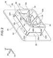
- the peripheral wall 22 is provided projecting out from the attachment plate 20 toward the vehicle rear side and, as illustrated in Fig. 2 , is formed with a peripheral shape so as to surround a central portion of the attachment plate 20 from the periphery.
- the peripheral wall 22 is also shaped so as to be housed in the interior 24 of the tube shaped energy absorption body 14A.
- the peripheral wall 22 is formed in a substantially rectangular shape as viewed from a direction perpendicular to the attachment plate 20, i.e. in a shape substantially corresponding to that of the energy absorption body 14A.
- the gaps referred to here are gaps measured in a direction perpendicular to each of the walls of the energy absorption body 14A.
- the gap from each of the walls forming the energy absorption body 14A (the top side wall 14T, the bottom side wall 14B, the outside wall 140, and the inside wall 14I) to the peripheral wall 22 facing each of the walls is respectively referred to as gap Gt, gap Gb, gap Go, and gap Gi.
- the gap Gt corresponds to the top side wall 14T
- the gap Gb corresponds to the bottom side wall 14B
- the gap Go corresponds to the outside wall 140
- the gap Gi corresponds to the inside wall 14I.
- the gap Gt, the gap Gb, the gap Go, and the gap Gi are sometimes referred to collectively as gaps G.
- the peripheral wall 22 is provided so as to be in proximity to each of the walls of the energy absorption body 14A, with a narrow gap G open thereto.
- the gap Gt is set so as to be smaller than the offset amount ⁇ Hb (Gt ⁇ ⁇ Hb).
- the gap Gb is set smaller than the offset amount ⁇ Ht (Gb ⁇ ⁇ Ht).
- the gap Go is set so as to be smaller than the offset amount ⁇ Hi (Go ⁇ ⁇ Hi).
- the gap Gi is set smaller than the offset amount ⁇ Ho (Gi ⁇ ⁇ Ho).
- the gaps Gt, Gb, Go, Gi are set to be about 2 mm.
- the peripheral wall 22 corresponds to the "abutting section" of the present invention.
- the portion of the peripheral wall 22 that is in proximity to the top side wall 14T of the energy absorption body 14A is referred to as a top side abutting wall 50t
- the portion thereof that is in proximity to the bottom side wall 14B is referred to as a bottom side abutting wall 50b
- the portion thereof that is in proximity to the inside wall 14I is referred to as an inside abutting wall 50i
- the portion thereof that is in proximity to the outside wall 140 is referred to as an outside abutting wall 50o.
- Escape holes 60 are formed in the peripheral wall 22.
- the positions of the escape holes 60 are at the base of the peripheral wall 22, namely portions further to the attachment plate 20 side than the abutting wall 50.
- the escape holes 60 are formed so as to leave remaining the boundary portion between the top side abutting wall 50t and the inside abutting wall 50i, the boundary portion between the inside abutting wall 50i and the bottom side abutting wall 50b, the boundary portion between the bottom side abutting wall 50b and the outside abutting wall 50o, and the boundary portion between the outside abutting wall 50o and the top abutting wall 50t. That is, a dimension of the escape hole 60 along a direction perpendicular to the axial direction is less than a dimension, along said perpendicular direction, of the abutting wall 50 on which said escape hole 60 is formed.
- the remaining portions thereof configure pillars 22H that support the peripheral wall 22.
- the inside and the outside of the peripheral wall 22 are configured so as to be in communication with each other at each of the portions on the attachment plate 20 side of the top side abutting wall 50t, the bottom side abutting wall 50b, the inside abutting wall 50i, and the outside abutting wall 50o.
- the escape holes 60 are formed as openings putting the space on the side of the abutting wall 50 that is the side of the walls forming the energy absorption body 14A, in communication with the space on the side of the abutting wall 50 that is the opposite side to the side of the walls forming the energy absorption body 14A.
- a dimension H of the escape holes 60 in the axial direction of the energy absorption body 14A is at least a thickness a of a wall forming the energy absorption body 14A or greater (see Fig. 3A ), and is preferably three times the thickness a of the wall forming the energy absorption body 14A or greater.
- ribs 26 are provided as "coupling portions" at the opposite side of the abutting wall 50 to the wall forming the energy absorption body 14A (namely, at the inside of the peripheral wall 22), so as to project out from the attachment plate 20 toward the vehicle rear direction side.
- the several ribs 26 are formed in a shape radiating out from a central portion of the attachment plate 20 (from a central portion at the inside of the peripheral wall 22).
- the leading end portion of each of the ribs 26 is coupled to the peripheral wall 22.
- the attachment plate 20 and the peripheral wall 22 are thereby coupled together by the several ribs 26.
- the abutting wall 50 can accordingly be said to be supported by the several ribs 26 and the pillars 22H.
- a tow hook fixing 80 formed with a female thread for screwing a tow hook, not illustrated in the drawings, into is formed at a base end side of the several ribs 26 (a central portion at the inside of the peripheral wall 22) (note that the hole for inserting the tow hook into is omitted from illustration in each of the drawings).
- a large load is input to the attachment plate 20 from the tow hook.
- the several ribs 26 have a function of raising the surface rigidity of the attachment plate 20.
- Each of the ribs 26 is formed in a shape as if cut out from a plate shaped member having its plate thickness direction along the circumferential direction of the peripheral wall 22.
- the plate shaped ribs 26 are coupled to the attachment plate 20, and are also coupled to the peripheral wall 22.
- Cutouts 26K are formed in the radiating shaped ribs 26 at the peripheral wall 22 side (leading end side), and at end portions thereof on the attachment plate 20 side (portions corresponding to the escape holes 60), as viewed from a vehicle side face.
- the ribs 26 include the cutouts 26K as "escape portions” such that crushed portions 90 of the energy absorption body 14A are not impeded from entering inside the peripheral wall 22.
- the cutouts 26K are formed in a substantially circular arc shape, such that the force to support the peripheral wall 22 by the ribs 26 is not impaired.
- the front ends of each of the tube shaped energy absorption bodies 14A made from fiber reinforced resin abut the attachment plates 20 of the guide members 18 that are joined to the rear face 16R of the bumper reinforcement 16.
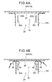
- the vehicle front section structure S includes the tube shaped energy absorption bodies 14A made from fiber reinforced resin, and the attachment plates 20 provided as "opposing faces" facing an axial direction end portion of the energy absorption body 14A. Then, during a vehicle collision, the attachment plate 20 crushes the energy absorption body 14A from the axial direction end portion (the vehicle front direction end portion) (see Fig. 4B ). Collision energy is thereby absorbed.
- vehicle front section structure S includes the peripheral wall 22 and the ribs 26 that project out from the attachment plate 20 and are disposed as a "guide section" at the interior 24 of the energy absorption body 14A.
- the peripheral wall 22 includes the abutting wall 50 as an "abutting section".
- the abutting wall 50 is provided so as to be capable of contacting walls (the top side wall 14T, the bottom side wall 14B, the outside wall 140, and the inside wall 14I) of the energy absorption body 14A from the inner side during a vehicle collision. Positional misalignment of the energy absorption body 14A with respect to the attachment plate 20 (and with respect to the bumper reinforcement 16 to which the attachment plate 20 is joined) is accordingly avoided during a vehicle collision.
- the escape holes 60 are formed at the end portions of the peripheral wall 22 on the attachment plate 20 side, and the part of the peripheral wall 22 further to the vehicle rear side than the escape holes 60 (on the opposite side to the attachment plate 20) forms the abutting wall 50.
- the abutting wall 50 is provided spaced away from the attachment plate 20 by an opening in the axial direction of the energy absorption body 14A (see Fig. 4A ).
- the opening is embodied by respective openings (the escape holes 60) putting the space on the side of the abutting wall 50 that is the side of the walls forming the energy absorption body 14A in communication with the space on the side of the abutting wall 50 that is the opposite side to the side of the walls forming the energy absorption body 14A.
- the crushed portions 90 that have entered into the interior 24 of the energy absorption body 14A are able to escape through these openings (the escape holes 60), to the space on the opposite side of the abutting wall 50 to the side of the walls forming the energy absorption body 14A (to the center side of the energy absorption body 14A, the inside of the peripheral wall 22).
- the crushed portions 90 are thereby prevented from getting jammed between the abutting wall 50 and the portions of the walls of the energy absorption body 14A that have not yet been crushed.
- the crushed portions 90 are generated in the vicinity of the attachment plate 20, this being at the axial direction end portion of the energy absorption body 14A, when the energy absorption body 14A is being crushed from the axial direction end section during a vehicle collision. Part of the crushed portions 90 then enters the interior 24 of the energy absorption body 14A (inside a closed cross-section).
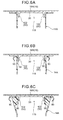
- the guide member 118 is not formed with an escape hole in a peripheral wall 122. Namely, as illustrated in Fig. 6A , an opening in the axial direction of the energy absorption body 14A is not formed between the abutting walls 50 and the attachment plate 20. Thus, as illustrated in Fig. 6B , the crushed portions 90 entering the interior of the energy absorption body 14A get jammed between the peripheral wall 122 and each of the walls of the energy absorption body 14A.
- the energy absorption body 14A receives load from the jammed crushed portions 90 in a direction orthogonal to the axial direction of the energy absorption body 14A (the front-rear direction), and, as illustrated in Fig. 6C , this leads to a concern that folding might occur at a part of the energy absorption body 14A partway along the axial direction. If the energy absorption body 14A folds at a portion partway along the axial direction, progressive deformation is impeded, with a reduction in the amount of energy absorption.
- the abutting wall 50 is provided spaced away from the attachment plate 20 by an opening (the escape hole 60) in the axial direction of the energy absorption body 14A.
- the crushed portions 90 are prevented from becoming jammed between the abutting wall 50 and the portions of the walls of the energy absorption body 14A that have not yet been crushed.
- the energy absorption body 14A is prevented from receiving load from the crushed portions 90 in a direction orthogonal to the axial direction of the energy absorption body 14A, enabling stable energy absorption properties to be obtained.
- the "abutting section" that contacts each of the walls of the energy absorption body 14A during a vehicle collision is formed by the abutting wall 50 provided substantially parallel to each of these walls (i.e. each abutting wall is respectively substantially parallel to a corresponding one of these walls).
- a large load is thereby prevented from being locally input to the walls of the energy absorption body 14A.
- the energy absorption body 14A is thereby prevented from breaking due to contact with the abutting wall 50.
- the guide members 18 includes the several ribs 26.
- the "guide section” includes the ribs 26 serving as “coupling portions” coupling the abutting wall 50 and the attachment plate 20 together.
- the abutting wall 50 can thereby be supported by the ribs 26, and this thereby facilitates forming a larger opening (the escape holes 60) between the abutting wall 50 and the attachment plate 20.
- the ribs 26 are disposed on the opposite side of the abutting wall 50 to the walls of the energy absorption body 14A. This thereby prevents the crushed portions 90 from getting jammed between the ribs 26 and the walls of the energy absorption body 14A.
- the cutouts 26K are formed in the ribs 26, and the ribs 26 include the cutouts 26K serving as "escape portions" such that the crushed portions 90 of the energy absorption body 14A are not impeded from entering the interior of the peripheral wall 22. The crushed portions 90 are thereby prevented even further from getting jammed between the abutting wall 50 and the ribs 26, and the walls of the energy absorption body 14A.
- the abutting wall 50 (the top side abutting wall 50t, the bottom side abutting wall 50b, the inside abutting wall 50i, and the outside abutting wall 50o) formed with the escape holes 60 is formed for each of the walls (the top side wall 14T, the bottom side wall 14B, the inside wall 14I, and the outside wall 140) forming the tube shaped energy absorption body 14A having a substantially rectangular shaped cross-section.
- the abutting wall 50 forms the peripheral wall 22 that is provided so as to correspond with the entire periphery of the walls forming the energy absorption body 14A.
- Positional misalignment between the energy absorption body 14A and the attachment plate 20 (the bumper reinforcement 16) is thereby appropriately prevented in all directions from the vehicle up-down directions and the vehicle width directions. Moreover, load from the crushed portions 90 is prevented from being input to each of the walls forming the energy absorption body 14A.
- FIG. 7 this diagram is a perspective view of a guide member, as viewed from diagonally to the rear and above a vehicle, and is a diagram corresponding to Fig. 2 of the above exemplary embodiment.
- a guide member 38 according to the modified example illustrated in Fig. 7 differs from the guide members 18 of the above exemplary embodiment in that the pillars 22H are not provided. Namely, the peripheral wall 22 is provided with an opening to the attachment plate 20 around the entire periphery. Thus the peripheral wall 22 is supported by several ribs 26 alone. Other parts of the configuration are substantially the same as those of the guide members 18 of the above exemplary embodiment.
- the peripheral wall 22 is supported by the ribs 26 alone, and there are no pillars 22H provided in the guide section.
- the peripheral wall 22 serving as the abutting section is supported by the ribs 26 alone, and the abutting wall 50 (the peripheral wall 22) and the attachment plate 20 are provided spaced away from each other by an opening (escape hole 60) around the entire periphery of the peripheral wall 22. Any concern that the crushed portions 90 might get jammed between pillars 22H and the walls forming the energy absorption body 14A is thereby eliminated, enabling even more stable energy absorption characteristics to be obtained.
- the energy absorption bodies 14A are configured with a substantially rectangular shaped cross-section tubular shape (closed cross-section structure); however, the present invention is not limited thereto. Any shape may be employed for the energy absorption bodies as long as it is a tubular shape (closed cross-section structure).
- the energy absorption bodies 14A are joined to the bumper reinforcement 16 through the front flange 14F, there are no particular limitations to the manner by which the energy absorption body 14A is joined to the bumper reinforcement 16.
- the vehicular energy absorption structure is applied to a vehicle front section structure equipped with the (front) bumper reinforcement 16 serving as bumper reinforcement
- the present invention is not limited thereto, and application may be made to a vehicle rear section structure equipped with rear bumper reinforcement provided extending along the vehicle width direction of a vehicle rear end portion.
- the present invention is not limited thereto.
- a configuration may be adopted in which the attachment plate 20 of the guide members 18 is formed smaller, and the front end of the energy absorption body 14A abuts the rear face 16R of the bumper reinforcement 16.
- a configuration may be adopted in which the attachment plate 20 of the guide members 18 is not interposed between the energy absorption body 14A and the bumper reinforcement 16.
- the rear face 16R of the bumper reinforcement 16 corresponds to the "opposing face" of the present invention.
- the offset amounts ⁇ Ht, ⁇ Hb, ⁇ Ho, ⁇ Hi explained in the above exemplary embodiment may be considered not as offset amounts to the attachment plate 20, but rather as offset amounts to the rear face 16R of the bumper reinforcement 16.
- the gaps Gt, Gb, Go, Gi are set at about 2 mm; however, the present invention is not limited thereto.
- the abutting section is configured to internally contact the walls forming the energy absorption body and prevent positional misalignment of the energy absorption body 14A with respect to the bumper reinforcement 16.
- the guide members 18 include the ribs 26 serving as "coupling portions"; however, the present invention is not limited thereto.
- the guide member may be configured omitting the ribs 26, with the abutting wall 50 supported by the pillars 22H alone.
- the peripheral wall 22 serving as the "abutting section" or the "abutting wall” is formed with a peripheral shape so as to surround a central portion of the attachment plate 20 from the periphery; however, the present invention is not limited thereto.
- the guide member may be formed with the inside abutting wall 50i and the outside abutting wall 50o corresponding to the inside wall 14I and the outside wall 140 of the energy absorption body 14A, without forming the top side abutting wall 50t and the bottom side abutting wall 50b.
- the guide member may be formed with the inside abutting wall 50i alone, without forming the other parts of the abutting wall 50.
- respective escape holes 60 are formed in the top side abutting wall 50t, the bottom side abutting wall 50b, the inside abutting wall 50i, and the outside abutting wall 50o of the peripheral wall 22; however, the present invention is not limited thereto.
- the present invention also encompasses embodiments in which the escape hole 60 is only formed in the inside abutting wall 50i. In such cases, the inside abutting wall 50i alone corresponds to the "abutting section" or the "abutting wall” of the present invention.
- the position of the escape holes 60 is at the foot of the peripheral wall 22, namely, in end portions of the abutting wall 50 on the attachment plate 20 side; however, the present invention is not limited thereto. It is sufficient that an opening is formed between the opposing face and the abutting section, and, for example, escape holes 60 (openings) may be formed such that a small portion at the foot of the peripheral wall 22 (indicated by dashed lines at 22N in Fig. 4A ) remains.
- the bumper reinforcement 16 and the guide members 18 are configured by separate members, and the two members are joined together; however, the present invention is not limited thereto.
- bumper reinforcement and guide members may be integrally molded.
Landscapes
- Engineering & Computer Science (AREA)
- General Engineering & Computer Science (AREA)
- Mechanical Engineering (AREA)
- Vibration Dampers (AREA)
- Body Structure For Vehicles (AREA)
Abstract
Description
- The embodiments discussed herein are related to an energy absorption structure for a vehicle.
-
JP-A No. 2005-233263 - A structure that is, such as in the above conventional technology, provided with a projection (guide section) that abuts the inside of the crash box, prevents positional misalignment of a crash box with respect to bumper reinforcement during a collision of a vehicle.
- However, the portion of the crash box that is crushed (crushed portion) enters between the crash box and the guide section as the crash box is being crushed during a vehicle collision. When load from ingress of the crushed portion is born by the crash box in a direction orthogonal to the axis of the crash box, this impedes the progressive deformation of the crash box, leading to concerns regarding a reduction in the amount of energy absorption.
- In consideration of the above circumstances, an object of the present invention is to obtain stable energy absorption characteristics in a vehicular energy absorption structure with a guide section provided internally to an tube shaped energy absorption body formed from fiber reinforced resin.
- A vehicular energy absorption structure according to a first aspect of the present disclosure is a vehicular energy absorption structure including a tube shaped energy absorption body made from a fiber reinforced resin, an opposing face that is provided facing an axial direction end portion of the energy absorption body, and that, during a vehicle collision, crushes the energy absorption body from the axial direction end portion, and a guide section that projects out from the opposing face and that is disposed at an interior of the energy absorption body, wherein the guide section comprises an abutting section, that is provided so as to be capable of contacting a wall configuring the energy absorption body from an inner side during a vehicle collision, and is separated from the opposing face by an opening in an axial direction of the energy absorption body.
- The vehicular energy absorption structure according to the first aspect of the present disclosure includes the tube shaped energy absorption body made from a fiber reinforced resin, and the opposing face that is provided facing an axial direction end portion of the energy absorption body. During a vehicle collision, the opposing face crushes the energy absorption body from the axial direction end portion. Collision energy is absorbed thereby.
- Moreover, the vehicular energy absorption structure also includes the guide section that projects out from the opposing face and that is disposed at the interior of the energy absorption body. The guide section includes the abutting section.
- The abutting section is provided so as to be capable of contacting the wall configuring (forming) the energy absorption body from the inner side during a vehicle collision. Positional misalignment of the energy absorption body with respect to the opposing face does thereby not occur during a vehicle collision.
- The abutting section is also separated from the opposing face by the opening in the axial direction of the energy absorption body. In other words, the guide section is provided with the opening located between the opposing face and the abutting section, in the axial direction. This opening is an opening (escape path) enabling communication of the space on the side of the abutting section at the side of the wall forming the energy absorption body, with the space on the side of the abutting section at the opposite side to the wall forming the energy absorption body. Thus, during a vehicle collision, crushed portions entering into the interior of the energy absorption body are able to escape through these openings, to the space on the side of the abutting section at the opposite side to the wall forming the energy absorption body (to the center side of the energy absorption body). This thereby prevents the crushed portions from becoming jammed between the abutting section and the portions of the wall forming the energy absorption body that have not yet been crushed.
- More precisely, when the energy absorption body is crushed from its axial direction end portion during a vehicle collision, crushed portions are generated in the vicinity of the opposing face, i.e. at the axial direction end portion of the energy absorption body. Thus, in the vehicular energy absorption structure according to the first aspect of the present disclosure, the abutting section is separated from the opposing face by an opening in the axial direction of the energy absorption body. The opening is accordingly formed in the vicinity of the opposing face. Thus due to the crushed portions being able to pass through the opening, the crushed portions are accordingly prevented from becoming jammed between the abutting section and the portions of the wall forming the energy absorption body that have not yet been crushed. As a result, the energy absorption body does not receive load from the crushed portions in a direction orthogonal to the axis of the energy absorption body, enabling stable energy absorption characteristics to be achieved.
- A vehicular energy absorption structure according to a second aspect of the present disclosure is the vehicular energy absorption structure according to the first aspect of the present disclosure, wherein the abutting section is an abutting wall that is substantially parallel to the wall configuring the energy absorption body.
- In the vehicular energy absorption structure according to the second aspect of the present disclosure, the abutting section, which is capable of contacting the wall forming the energy absorption body from the inner side during a vehicle collision, is the wall provided substantially parallel to the wall forming the energy absorption body. Portions of the abutting wall are respectively parallel to corresponding portions of the wall forming the energy absorption body. The abutting wall may be coaxial with the wall forming the energy absorption body. A large load is thereby prevented from being locally input to the wall forming the energy absorption body. This thereby prevents the energy absorption body from being broken by contact with the abutting section.
- A vehicular energy absorption structure according to a third aspect of the present disclosure is the vehicular energy absorption structure according to the second aspect of the present disclosure, wherein the guide section includes a coupling portion that is disposed on an opposite side of the abutting wall from the wall configuring the energy absorption body, and that couples the abutting wall and the opposing face together.
- In the vehicular energy absorption structure according to the third aspect of the present disclosure, the guide section includes the coupling portion that couples the abutting wall and the opposing face together. More generally, the coupling portion couples the guide section and the opposing face. This thereby enables the abutting wall to be supported by the coupling portion, and, as a result, facilitates forming of a larger opening between the abutting wall and the opposing face. The coupling portion is disposed on the opposite side of the abutting wall from the side of the wall forming the energy absorption body. Thus the crushed portions are accordingly prevented from becoming jammed between the coupling portion and the wall forming the energy absorption body.
- A vehicular energy absorption structure according to a fourth aspect of the present disclosure is the vehicular energy absorption structure according to the second aspect of the present disclosure, wherein the abutting wall is a peripheral wall corresponding to an entire periphery of the wall configuring the energy absorption body, the guide section is disposed at an interior of the peripheral wall and includes a coupling portion that couples the peripheral wall and the opposing face together, and the peripheral wall and the opposing face are separated from each other by an opening around an entire periphery of the peripheral wall.
- In the vehicular energy absorption structure according to the fourth aspect of the present disclosure, the abutting wall is a peripheral wall provided corresponding to the entire periphery of the wall forming the energy absorption body. Thus positional misalignment between the energy absorption body and the opposing face is thereby appropriately avoided in all directions from the vehicle up-down directions and the vehicle width directions.
- Moreover, the guide section is disposed at the interior of the peripheral wall and includes the coupling portion that couples the peripheral wall and the opposing face together. The peripheral wall is accordingly supported by the coupling portion. Moreover, due to the peripheral wall being supported by the coupling portion, the peripheral wall and the opposing face are separated from each other by an opening around the entire periphery of the peripheral wall. This thereby enables the crushed portions of the energy absorption body to escape into the interior of the peripheral wall around the entire periphery of the energy absorption body. This thereby enables even more stable energy absorption characteristics to be obtained.
- As explained above, the vehicular energy absorption structure according to the first aspect of the present disclosure enables even more stable energy absorption characteristics to be obtained in a vehicular energy absorption structure provided with a guide section at the interior of a tube shaped energy absorption body made from a fiber reinforced resin.
-
-
Fig. 1 is an exploded perspective view illustrating an overall configuration of a vehicle front section structure applied with a vehicular energy absorption structure of an exemplary embodiment of the present invention, in a dismantled state of bumper reinforcement and crash boxes. -
Fig. 2 is a perspective view of the guide member on the left side inFig. 1 , as viewed from diagonally behind and above a vehicle. -
Figs. 3A and 3B are cross-sections of a vehicle front section structure of an exemplary embodiment;Fig. 3A is a cross-section illustrating a state sectioned along a plane orthogonal to a vehicle width direction, andFig. 3B is a cross-section illustrating a state sectioned along a plane orthogonal to a vehicle up-down direction. -
Figs. 4A and 4B are diagrams illustrating a manner in which an energy absorption body crushes during a vehicle collision in a vehicle front section structure according to an exemplary embodiment. -
Fig. 5 is a perspective view illustrating a guide member according to a comparative example. -
Figs. 6A, 6B, and 6C are diagrams illustrating a manner in which an energy absorption body crushes in a vehicle front section structure provided with a guide member according to a comparative example. -
Fig. 7 is a perspective view illustrating a guide member according to a modified example of the present invention. - Explanation follows regarding a vehicle front section structure S applied with a vehicular energy absorption structure according to an exemplary embodiment of the present invention, with reference to the drawings. Note that the arrows FR, the arrows UP, the arrows OUT, and the arrows W applied in each of the drawings respectively indicate a front direction (direction of progression), an up direction, outside in a vehicle width direction, and a vehicle width direction, of a vehicle. Unless stated otherwise, reference in the following simply to front or rear, left or right, or up or down directions indicates front or rear in a vehicle front-rear direction, left or right in a vehicle left-right direction (vehicle width direction), or up or down in a vehicle up-down direction.
-
Fig. 1 is an exploded perspective view illustrating an overall configuration of a vehicle front section structure S. As illustrated therein, the vehicle front section structure S includes abumper reinforcement 16 that is present extending in the vehicle front end section along a vehicle width direction. A pair of left andright guide members 18 are respectively joined torear faces 16R at a vehicle rear side of thebumper reinforcement 16. A pair of left andright crash boxes 14 are respectively joined to portions at the vehicle rear side of thebumper reinforcement 16 corresponding to theguide members 18. Moreover, at the rear of the left and right pair ofcrash boxes 14, front side members (not illustrated in the drawings), which are framework members having their length direction along the vehicle front-rear direction, are coaxially jointed to thecrash boxes 14. - The
bumper reinforcement 16 has a closed cross-section structure formed with a substantially rectangular shape in cross-section orthogonal to the length direction, and includes anupper face 16U facing upward, alower face 16L facing downward, arear face 16R facing rearward, and afront face 16F facing forward. - The
crash boxes 14 are joined to thebumper reinforcement 16 at the vehicle rear side (seeFig. 3 ). Thecrash boxes 14 are provided parallel to each other as a left and right pair. - The
crash boxes 14 are formed from fiber reinforced resin. Thecrash boxes 14 each includes a tube shapedenergy absorption body 14A, afront flange 14F provided as a joint portion to a front end of theenergy absorption body 14A, and arear flange 14R provided to a rear end of theenergy absorption body 14A. - The
energy absorption body 14A has a tube shape (closed cross-section structure), e.g. of substantially rectangular cross-section, including atop side wall 14T facing upward, abottom side wall 14B facing downward, an inside wall 14I facing toward a vehicle width direction inside, and anoutside wall 140 facing toward a vehicle width direction outside. - The
front flange 14F is formed extending from a front end of theenergy absorption body 14A along an up-down direction, and is joined to thebumper reinforcement 16, in a state in which theupper face 16U and thelower face 16L of thebumper reinforcement 16 are held therein. Adhesive bonding, welding, riveting or the like may, for example, be employed for such joining. More specifically, thefront flange 14F includes a front wall 14FF that juts out from the front end of theenergy absorption body 14A toward the top and bottom and left and right, an upper wall 14FU that extends out forward from an upper end of the front wall 14FF, and a lower wall 14FL that extends out forward from a lower end of the front wall 14FF. - As illustrated in
Figs. 3A and 3B , the front wall 14FF of thefront flange 14F, and the front end of theenergy absorption body 14A, together abut anattachment plate 20 of each of theguide members 18, described later. In this state, the upper wall 14FU and the lower wall 14FL are respectively joined to theupper face 16U and thelower face 16L of thebumper reinforcement 16. Due to the above, thefront flange 14F serving as a joint portion is respectively joined to both upper and lower direction ends of thebumper reinforcement 16. Adhesive bonding, welding, riveting or the like may, for example, be employed in such a joining state. At the front wall 14FF, the front wall 14FF is fastened together with theattachment plate 20 of each of theguide members 18, and therear face 16R of thebumper reinforcement 16. - The vehicle front section structure S includes the
guide members 18, each serving as a "guide section" and including aperipheral wall 22 andribs 26. Theguide members 18 each includes theattachment plate 20 joined to therear face 16R of thebumper reinforcement 16, and theperipheral wall 22 and theribs 26 formed projecting out from theattachment plate 20. Namely, theperipheral wall 22 and theribs 26 of each of theguide members 18 project out from theattachment plate 20 toward the rear. As illustrated inFigs. 3A and 3B , theperipheral wall 22 and theribs 26 of each of theguide members 18 fit into an interior 24 of theenergy absorption body 14A having a closed cross-section structure. - Each of the
guide members 18 is configured to prevent positional misalignment of theenergy absorption body 14A with respect to theattachment plate 20 and thebumper reinforcement 16, when joining of theenergy absorption body 14A to thebumper reinforcement 16 and theattachment plate 20, through thefront flange 14F, has been released (separated). In other words, each of theguide members 18 is a guide member that guides each front-rear direction portion of theenergy absorption body 14A toward an appropriate location on theattachment plate 20 and thebumper reinforcement 16 as theenergy absorption body 14A is being broken under compression from the front. - More specifically, as illustrated in
Fig. 2 , theguide members 18 each includes, as main parts thereof, theattachment plate 20 that is joined in a superimposed state to therear face 16R of thebumper reinforcement 16, theperipheral wall 22 that projects out from theattachment plate 20 toward the vehicle rear side, and at least onerib 26, hereseveral ribs 26 that are formed in a shape radiating out from a center of theattachment plate 20 and that reinforce theattachment plate 20 and theperipheral wall 22. - The
attachment plate 20 is configured in a substantially rectangular plate shape. As illustrated inFig. 3A , the upper end of theattachment plate 20 is substantially aligned with the upper end of therear face 16R of thebumper reinforcement 16, and the lower end of theattachment plate 20 is substantially aligned with the lower end of therear face 16R of thebumper reinforcement 16. In a state in which each of thecrash boxes 14 is joined to thebumper reinforcement 16, the two up-down direction ends of theenergy absorption body 14A are positioned between the two up-down direction ends of theattachment plate 20. More specifically, the upper end of theattachment plate 20 is positioned by an amount ΔHt further toward the vehicle top than thetop side wall 14T of theenergy absorption body 14A, and the lower end of theattachment plate 20 is positioned by an amount ΔHb further toward the vehicle bottom than thebottom side wall 14B of theenergy absorption body 14A. - As illustrated in
Fig. 3B , in a state in which each of thecrash boxes 14 is joined to thebumper reinforcement 16, the two left-right direction ends of theenergy absorption body 14A are positioned between the two left-right direction ends of theattachment plate 20. More specifically, a vehicle width direction outside end of theattachment plate 20 is positioned by an amount ΔHo further toward the vehicle width direction outside than theoutside wall 140 of theenergy absorption body 14A, and the vehicle width direction inside end of theattachment plate 20 is positioned by an amount ΔHi further toward the vehicle width direction inside than the inside wall 14I of theenergy absorption body 14A. - The
peripheral wall 22 is provided projecting out from theattachment plate 20 toward the vehicle rear side and, as illustrated inFig. 2 , is formed with a peripheral shape so as to surround a central portion of theattachment plate 20 from the periphery. Theperipheral wall 22 is also shaped so as to be housed in theinterior 24 of the tube shapedenergy absorption body 14A. In this embodiment, theperipheral wall 22 is formed in a substantially rectangular shape as viewed from a direction perpendicular to theattachment plate 20, i.e. in a shape substantially corresponding to that of theenergy absorption body 14A. - Next, explanation follows regarding a gap from each of the walls forming the
energy absorption body 14A (thetop side wall 14T, thebottom side wall 14B, the inside wall 14I, and the outside wall 140), to theperipheral wall 22. The gaps referred to here are gaps measured in a direction perpendicular to each of the walls of theenergy absorption body 14A. - In the following explanation, as illustrated in
Fig. 3A and Fig. 3B , the gap from each of the walls forming theenergy absorption body 14A (thetop side wall 14T, thebottom side wall 14B, theoutside wall 140, and the inside wall 14I) to theperipheral wall 22 facing each of the walls is respectively referred to as gap Gt, gap Gb, gap Go, and gap Gi. The gap Gt corresponds to thetop side wall 14T, the gap Gb corresponds to thebottom side wall 14B, the gap Go corresponds to theoutside wall 140, and the gap Gi corresponds to the inside wall 14I. The gap Gt, the gap Gb, the gap Go, and the gap Gi are sometimes referred to collectively as gaps G. - The
peripheral wall 22 is provided so as to be in proximity to each of the walls of theenergy absorption body 14A, with a narrow gap G open thereto. - More specifically, as illustrated in
Fig. 3A , the gap Gt is set so as to be smaller than the offset amount ΔHb (Gt < ΔHb). Thus even if thetop side wall 14T was to move downward by an amount of gap Gt, a state is maintained in which thebottom side wall 14B and theattachment plate 20 face each other along the front-rear direction. Moreover, the gap Gb is set smaller than the offset amount ΔHt (Gb < ΔHt). Thus even if thebottom side wall 14B was to move upward by an amount of gap Gb, a state is maintained in which thetop side wall 14T and theattachment plate 20 face each other along the front-rear direction. - Moreover, as illustrated in
Fig. 3B , the gap Go is set so as to be smaller than the offset amount ΔHi (Go < ΔHi). Thus even if theoutside wall 140 was to move toward the vehicle inside by an amount of gap Go, a state is maintained in which the inside wall 14I and theattachment plate 20 face each other along the vehicle front-rear direction. Moreover, the gap Gi is set smaller than the offset amount ΔHo (Gi < ΔHo). Thus even if the inside wall 14I was to move toward the vehicle outside by an amount of gap Gi, a state is maintained in which theoutside wall 140 and theattachment plate 20 face each other along the vehicle front-rear direction. - In the present exemplary embodiment, the gaps Gt, Gb, Go, Gi are set to be about 2 mm. The
peripheral wall 22 corresponds to the "abutting section" of the present invention. In the following, the portion of theperipheral wall 22 that is in proximity to thetop side wall 14T of theenergy absorption body 14A is referred to as a topside abutting wall 50t, the portion thereof that is in proximity to thebottom side wall 14B is referred to as a bottomside abutting wall 50b, the portion thereof that is in proximity to the inside wall 14I is referred to as aninside abutting wall 50i, and the portion thereof that is in proximity to theoutside wall 140 is referred to as an outside abutting wall 50o. These are all sometimes simply referred to collectively as an abuttingwall 50. - Escape holes 60 are formed in the
peripheral wall 22. In this embodiment, there are a total of four of the escape holes 60 formed, each respectively formed in the topside abutting wall 50t, the bottomside abutting wall 50b, theinside abutting wall 50i, and the outside abutting wall 50o. The positions of the escape holes 60 are at the base of theperipheral wall 22, namely portions further to theattachment plate 20 side than the abuttingwall 50. The escape holes 60 are formed so as to leave remaining the boundary portion between the topside abutting wall 50t and theinside abutting wall 50i, the boundary portion between theinside abutting wall 50i and the bottomside abutting wall 50b, the boundary portion between the bottomside abutting wall 50b and the outside abutting wall 50o, and the boundary portion between the outside abutting wall 50o and thetop abutting wall 50t. That is, a dimension of theescape hole 60 along a direction perpendicular to the axial direction is less than a dimension, along said perpendicular direction, of the abuttingwall 50 on which saidescape hole 60 is formed. The remaining portions thereof (corner portions) configurepillars 22H that support theperipheral wall 22. - In the configuration described above, the inside and the outside of the
peripheral wall 22 are configured so as to be in communication with each other at each of the portions on theattachment plate 20 side of the topside abutting wall 50t, the bottomside abutting wall 50b, theinside abutting wall 50i, and the outside abutting wall 50o. In other words, the escape holes 60 are formed as openings putting the space on the side of the abuttingwall 50 that is the side of the walls forming theenergy absorption body 14A, in communication with the space on the side of the abuttingwall 50 that is the opposite side to the side of the walls forming theenergy absorption body 14A. - A dimension H of the escape holes 60 in the axial direction of the
energy absorption body 14A (a dimension in the vehicle front-rear direction in the present exemplary embodiment) is at least a thickness a of a wall forming theenergy absorption body 14A or greater (seeFig. 3A ), and is preferably three times the thickness a of the wall forming theenergy absorption body 14A or greater. - Several of the
ribs 26 are provided as "coupling portions" at the opposite side of the abuttingwall 50 to the wall forming theenergy absorption body 14A (namely, at the inside of the peripheral wall 22), so as to project out from theattachment plate 20 toward the vehicle rear direction side. Theseveral ribs 26 are formed in a shape radiating out from a central portion of the attachment plate 20 (from a central portion at the inside of the peripheral wall 22). The leading end portion of each of theribs 26 is coupled to theperipheral wall 22. Theattachment plate 20 and theperipheral wall 22 are thereby coupled together by theseveral ribs 26. The abuttingwall 50 can accordingly be said to be supported by theseveral ribs 26 and thepillars 22H. - A tow hook fixing 80 formed with a female thread for screwing a tow hook, not illustrated in the drawings, into is formed at a base end side of the several ribs 26 (a central portion at the inside of the peripheral wall 22) (note that the hole for inserting the tow hook into is omitted from illustration in each of the drawings). A large load is input to the
attachment plate 20 from the tow hook. Theseveral ribs 26 have a function of raising the surface rigidity of theattachment plate 20. - Each of the
ribs 26 is formed in a shape as if cut out from a plate shaped member having its plate thickness direction along the circumferential direction of theperipheral wall 22. Namely, the plate shapedribs 26 are coupled to theattachment plate 20, and are also coupled to theperipheral wall 22.Cutouts 26K are formed in the radiating shapedribs 26 at theperipheral wall 22 side (leading end side), and at end portions thereof on theattachment plate 20 side (portions corresponding to the escape holes 60), as viewed from a vehicle side face. Thus theribs 26 include thecutouts 26K as "escape portions" such that crushedportions 90 of theenergy absorption body 14A are not impeded from entering inside theperipheral wall 22. Moreover, in the present exemplary embodiment, thecutouts 26K are formed in a substantially circular arc shape, such that the force to support theperipheral wall 22 by theribs 26 is not impaired. - Next, explanation follows regarding operation and advantageous effects of the vehicle front section structure S of the present exemplary embodiment.
- In the vehicle front section structure S of the exemplary embodiment, the front ends of each of the tube shaped
energy absorption bodies 14A made from fiber reinforced resin abut theattachment plates 20 of theguide members 18 that are joined to therear face 16R of thebumper reinforcement 16. Namely, the vehicle front section structure S includes the tube shapedenergy absorption bodies 14A made from fiber reinforced resin, and theattachment plates 20 provided as "opposing faces" facing an axial direction end portion of theenergy absorption body 14A. Then, during a vehicle collision, theattachment plate 20 crushes theenergy absorption body 14A from the axial direction end portion (the vehicle front direction end portion) (seeFig. 4B ). Collision energy is thereby absorbed. - Moreover, the vehicle front section structure S includes the
peripheral wall 22 and theribs 26 that project out from theattachment plate 20 and are disposed as a "guide section" at the interior 24 of theenergy absorption body 14A. - The
peripheral wall 22 includes the abuttingwall 50 as an "abutting section". The abuttingwall 50 is provided so as to be capable of contacting walls (thetop side wall 14T, thebottom side wall 14B, theoutside wall 140, and the inside wall 14I) of theenergy absorption body 14A from the inner side during a vehicle collision. Positional misalignment of theenergy absorption body 14A with respect to the attachment plate 20 (and with respect to thebumper reinforcement 16 to which theattachment plate 20 is joined) is accordingly avoided during a vehicle collision. - Moreover, the escape holes 60 are formed at the end portions of the
peripheral wall 22 on theattachment plate 20 side, and the part of theperipheral wall 22 further to the vehicle rear side than the escape holes 60 (on the opposite side to the attachment plate 20) forms the abuttingwall 50. Namely, the abuttingwall 50 is provided spaced away from theattachment plate 20 by an opening in the axial direction of theenergy absorption body 14A (seeFig. 4A ). The opening is embodied by respective openings (the escape holes 60) putting the space on the side of the abuttingwall 50 that is the side of the walls forming theenergy absorption body 14A in communication with the space on the side of the abuttingwall 50 that is the opposite side to the side of the walls forming theenergy absorption body 14A. Thus, during a vehicle collision, as illustrated inFig. 4B , the crushedportions 90 that have entered into the interior 24 of theenergy absorption body 14A are able to escape through these openings (the escape holes 60), to the space on the opposite side of the abuttingwall 50 to the side of the walls forming theenergy absorption body 14A (to the center side of theenergy absorption body 14A, the inside of the peripheral wall 22). The crushedportions 90 are thereby prevented from getting jammed between the abuttingwall 50 and the portions of the walls of theenergy absorption body 14A that have not yet been crushed. - A more detailed explanation is that, as illustrated in
Fig. 4B andFig. 6B , the crushedportions 90 are generated in the vicinity of theattachment plate 20, this being at the axial direction end portion of theenergy absorption body 14A, when theenergy absorption body 14A is being crushed from the axial direction end section during a vehicle collision. Part of the crushedportions 90 then enters the interior 24 of theenergy absorption body 14A (inside a closed cross-section). - Explanation first follows regarding a
guide member 118 in the comparative example illustrated inFig. 5 . Theguide member 118 is not formed with an escape hole in aperipheral wall 122. Namely, as illustrated inFig. 6A , an opening in the axial direction of theenergy absorption body 14A is not formed between the abuttingwalls 50 and theattachment plate 20. Thus, as illustrated inFig. 6B , the crushedportions 90 entering the interior of theenergy absorption body 14A get jammed between theperipheral wall 122 and each of the walls of theenergy absorption body 14A. Theenergy absorption body 14A receives load from the jammed crushedportions 90 in a direction orthogonal to the axial direction of theenergy absorption body 14A (the front-rear direction), and, as illustrated inFig. 6C , this leads to a concern that folding might occur at a part of theenergy absorption body 14A partway along the axial direction. If theenergy absorption body 14A folds at a portion partway along the axial direction, progressive deformation is impeded, with a reduction in the amount of energy absorption. - In contrast thereto, in the vehicle front section structure S of the present exemplary embodiment, the abutting
wall 50 is provided spaced away from theattachment plate 20 by an opening (the escape hole 60) in the axial direction of theenergy absorption body 14A. As illustrated inFig. 4B , due to the crushedportions 90 passing through this opening, the crushedportions 90 are prevented from becoming jammed between the abuttingwall 50 and the portions of the walls of theenergy absorption body 14A that have not yet been crushed. As a result, theenergy absorption body 14A is prevented from receiving load from the crushedportions 90 in a direction orthogonal to the axial direction of theenergy absorption body 14A, enabling stable energy absorption properties to be obtained. - In the vehicle front section structure S of the present exemplary embodiment, the "abutting section" that contacts each of the walls of the
energy absorption body 14A during a vehicle collision is formed by the abuttingwall 50 provided substantially parallel to each of these walls (i.e. each abutting wall is respectively substantially parallel to a corresponding one of these walls). A large load is thereby prevented from being locally input to the walls of theenergy absorption body 14A. Theenergy absorption body 14A is thereby prevented from breaking due to contact with the abuttingwall 50. - Moreover, in the vehicle front section structure S of the present exemplary embodiment, the
guide members 18 includes theseveral ribs 26. Namely, the "guide section" includes theribs 26 serving as "coupling portions" coupling the abuttingwall 50 and theattachment plate 20 together. The abuttingwall 50 can thereby be supported by theribs 26, and this thereby facilitates forming a larger opening (the escape holes 60) between the abuttingwall 50 and theattachment plate 20. Moreover, theribs 26 are disposed on the opposite side of the abuttingwall 50 to the walls of theenergy absorption body 14A. This thereby prevents the crushedportions 90 from getting jammed between theribs 26 and the walls of theenergy absorption body 14A. - Moreover, in the vehicle front section structure S of the present exemplary embodiment, the
cutouts 26K are formed in theribs 26, and theribs 26 include thecutouts 26K serving as "escape portions" such that the crushedportions 90 of theenergy absorption body 14A are not impeded from entering the interior of theperipheral wall 22. The crushedportions 90 are thereby prevented even further from getting jammed between the abuttingwall 50 and theribs 26, and the walls of theenergy absorption body 14A. - In the vehicle front section structure S of the present exemplary embodiment, the abutting wall 50 (the top
side abutting wall 50t, the bottomside abutting wall 50b, theinside abutting wall 50i, and the outside abutting wall 50o) formed with the escape holes 60 is formed for each of the walls (thetop side wall 14T, thebottom side wall 14B, the inside wall 14I, and the outside wall 140) forming the tube shapedenergy absorption body 14A having a substantially rectangular shaped cross-section. Namely, the abuttingwall 50 forms theperipheral wall 22 that is provided so as to correspond with the entire periphery of the walls forming theenergy absorption body 14A. Positional misalignment between theenergy absorption body 14A and the attachment plate 20 (the bumper reinforcement 16) is thereby appropriately prevented in all directions from the vehicle up-down directions and the vehicle width directions. Moreover, load from the crushedportions 90 is prevented from being input to each of the walls forming theenergy absorption body 14A. - In the present exemplary embodiment, explanation has been given regarding the
guide members 18 including thepillars 22H; however, the present invention is not limited thereto. For example, the configuration of a modified example may be adopted, such as that illustrated inFig. 7 . Note that this diagram is a perspective view of a guide member, as viewed from diagonally to the rear and above a vehicle, and is a diagram corresponding toFig. 2 of the above exemplary embodiment. - A
guide member 38 according to the modified example illustrated inFig. 7 differs from theguide members 18 of the above exemplary embodiment in that thepillars 22H are not provided. Namely, theperipheral wall 22 is provided with an opening to theattachment plate 20 around the entire periphery. Thus theperipheral wall 22 is supported byseveral ribs 26 alone. Other parts of the configuration are substantially the same as those of theguide members 18 of the above exemplary embodiment. - Next, explanation follows of the operation and advantageous effects of the above modified example, regarding parts that differ from the above exemplary embodiment.
- In the above modified example, the
peripheral wall 22 is supported by theribs 26 alone, and there are nopillars 22H provided in the guide section. Namely, theperipheral wall 22 serving as the abutting section is supported by theribs 26 alone, and the abutting wall 50 (the peripheral wall 22) and theattachment plate 20 are provided spaced away from each other by an opening (escape hole 60) around the entire periphery of theperipheral wall 22. Any concern that the crushedportions 90 might get jammed betweenpillars 22H and the walls forming theenergy absorption body 14A is thereby eliminated, enabling even more stable energy absorption characteristics to be obtained. - In the above exemplary embodiments, the
energy absorption bodies 14A are configured with a substantially rectangular shaped cross-section tubular shape (closed cross-section structure); however, the present invention is not limited thereto. Any shape may be employed for the energy absorption bodies as long as it is a tubular shape (closed cross-section structure). Moreover, although in the above exemplary embodiments theenergy absorption bodies 14A are joined to thebumper reinforcement 16 through thefront flange 14F, there are no particular limitations to the manner by which theenergy absorption body 14A is joined to thebumper reinforcement 16. Moreover, although in the above exemplary embodiments the vehicular energy absorption structure is applied to a vehicle front section structure equipped with the (front)bumper reinforcement 16 serving as bumper reinforcement, the present invention is not limited thereto, and application may be made to a vehicle rear section structure equipped with rear bumper reinforcement provided extending along the vehicle width direction of a vehicle rear end portion. - Moreover, although in the above exemplary embodiments the front end of the
energy absorption body 14A abuts theattachment plate 20 of theguide members 18, the present invention is not limited thereto. For example, a configuration may be adopted in which theattachment plate 20 of theguide members 18 is formed smaller, and the front end of theenergy absorption body 14A abuts therear face 16R of thebumper reinforcement 16. Namely, a configuration may be adopted in which theattachment plate 20 of theguide members 18 is not interposed between theenergy absorption body 14A and thebumper reinforcement 16. In such cases therear face 16R of thebumper reinforcement 16 corresponds to the "opposing face" of the present invention. Moreover, the offset amounts ΔHt, ΔHb, ΔHo, ΔHi explained in the above exemplary embodiment may be considered not as offset amounts to theattachment plate 20, but rather as offset amounts to therear face 16R of thebumper reinforcement 16. - Moreover, in the above exemplary embodiment, the gaps Gt, Gb, Go, Gi are set at about 2 mm; however, the present invention is not limited thereto. In cases in which joining of the energy absorption body to the bumper reinforcement is released (separated) during a vehicle collision, it is sufficient that the abutting section is configured to internally contact the walls forming the energy absorption body and prevent positional misalignment of the
energy absorption body 14A with respect to thebumper reinforcement 16. - In the above exemplary embodiment, the
guide members 18 include theribs 26 serving as "coupling portions"; however, the present invention is not limited thereto. For example, the guide member may be configured omitting theribs 26, with the abuttingwall 50 supported by thepillars 22H alone. - In the present exemplary embodiment, the
peripheral wall 22 serving as the "abutting section" or the "abutting wall" is formed with a peripheral shape so as to surround a central portion of theattachment plate 20 from the periphery; however, the present invention is not limited thereto. For example, the guide member may be formed with theinside abutting wall 50i and the outside abutting wall 50o corresponding to the inside wall 14I and theoutside wall 140 of theenergy absorption body 14A, without forming the topside abutting wall 50t and the bottomside abutting wall 50b. Moreover, the guide member may be formed with theinside abutting wall 50i alone, without forming the other parts of the abuttingwall 50. - In the above exemplary embodiment, respective escape holes 60 are formed in the top
side abutting wall 50t, the bottomside abutting wall 50b, theinside abutting wall 50i, and the outside abutting wall 50o of theperipheral wall 22; however, the present invention is not limited thereto. For example, the present invention also encompasses embodiments in which theescape hole 60 is only formed in theinside abutting wall 50i. In such cases, theinside abutting wall 50i alone corresponds to the "abutting section" or the "abutting wall" of the present invention. - In the above exemplary embodiments, the position of the escape holes 60 is at the foot of the
peripheral wall 22, namely, in end portions of the abuttingwall 50 on theattachment plate 20 side; however, the present invention is not limited thereto. It is sufficient that an opening is formed between the opposing face and the abutting section, and, for example, escape holes 60 (openings) may be formed such that a small portion at the foot of the peripheral wall 22 (indicated by dashed lines at 22N inFig. 4A ) remains. - In the present exemplary embodiment, the
bumper reinforcement 16 and theguide members 18 are configured by separate members, and the two members are joined together; however, the present invention is not limited thereto. For example, bumper reinforcement and guide members may be integrally molded. - The entire contents of
Japanese Patent Application No. 2015-188563, filed on September 25, 2015 - All cited documents, patent applications and technical standards mentioned in the present specification are incorporated by reference in the present specification to the same extent as if the individual cited document, patent application, or technical standard was specifically and individually indicated to be incorporated by reference.
Claims (4)
- A vehicular energy absorption structure (S), comprising:a tube shaped energy absorption body (14A) made from a fiber reinforced resin;an opposing face (20) that is provided facing an axial direction end portion of the energy absorption body (14A), and that is configured, during a vehicle collision, to crush the energy absorption body (14A) from the axial direction end portion; anda guide section (22, 26) that projects out from the opposing face (20) and that is disposed at an interior (24) of the energy absorption body (14A),wherein the guide section (22, 26) comprises an abutting section (50), that is provided so as to be capable of contacting a wall (14B, 14I, 140, 14T) forming the energy absorption body (14A) from an inner side during a vehicle collision, and is separated from the opposing face (20) by an opening (60) in an axial direction of the energy absorption body (14A).
- The vehicular energy absorption structure (S) of claim 1, wherein the abutting section (50) is an abutting wall (50b, 50i, 50o, 50t) that is substantially parallel to the wall (14B, 14I, 140, 14T) forming the energy absorption body (14A).
- The vehicular energy absorption structure (S) of claim 2, wherein the guide section (22, 26) comprises a coupling portion (26) that is disposed on an opposite side of the abutting wall (50b, 50i, 50o, 50t) from the wall (14B, 14I, 140, 14T) forming the energy absorption body (14A), and that couples the abutting wall (50b, 50i, 50o, 50t) and the opposing face (20) together.
- The energy absorption structure (S) of claim 2, wherein:the abutting wall (50b, 50i, 50o, 50t) is a peripheral wall (22) corresponding to an entire periphery of the wall (14B, 14I, 140, 14T) forming the energy absorption body (14A);the guide section (22, 26) is disposed at an interior of the peripheral wall (22) and comprises a coupling portion (26) that couples the peripheral wall (22) and the opposing face (20) together; andthe peripheral wall (22) and the opposing face (20) are separated from each other by an opening (60) around an entire periphery of the peripheral wall (22).
Applications Claiming Priority (1)
| Application Number | Priority Date | Filing Date | Title |
|---|---|---|---|
| JP2015188563A JP6308194B2 (en) | 2015-09-25 | 2015-09-25 | Vehicle energy absorption structure |
Publications (2)
| Publication Number | Publication Date |
|---|---|
| EP3147163A1 true EP3147163A1 (en) | 2017-03-29 |
| EP3147163B1 EP3147163B1 (en) | 2018-09-26 |
Family
ID=56615893
Family Applications (1)
| Application Number | Title | Priority Date | Filing Date |
|---|---|---|---|
| EP16183292.8A Not-in-force EP3147163B1 (en) | 2015-09-25 | 2016-08-09 | Vehicular energy absorption structure |
Country Status (4)
| Country | Link |
|---|---|
| US (1) | US9932006B2 (en) |
| EP (1) | EP3147163B1 (en) |
| JP (1) | JP6308194B2 (en) |
| CN (1) | CN106553604B (en) |
Cited By (3)
| Publication number | Priority date | Publication date | Assignee | Title |
|---|---|---|---|---|
| US20170057440A1 (en) * | 2015-08-31 | 2017-03-02 | Toyota Jidosha Kabushiki Kaisha | Energy absorbing structure of vehicle |
| CN110065459A (en) * | 2019-04-12 | 2019-07-30 | 湖南文理学院 | A kind of automobile mechanical impact attenuation device |
| CN112032233A (en) * | 2020-08-17 | 2020-12-04 | 西安交通大学 | A kind of biomimetic composite material structure and manufacturing method with high specific energy absorption |
Families Citing this family (6)
| Publication number | Priority date | Publication date | Assignee | Title |
|---|---|---|---|---|
| KR101629100B1 (en) * | 2014-11-26 | 2016-06-09 | 롯데케미칼 주식회사 | Bumper system for vehicles |
| US10464511B2 (en) * | 2015-07-08 | 2019-11-05 | Nippon Steel Corporation | Bumper reinforcement and vehicle including the same |
| JP7053421B2 (en) * | 2018-09-17 | 2022-04-12 | 本田技研工業株式会社 | Body structure |
| EP3666597B1 (en) * | 2018-12-12 | 2020-11-18 | C.R.F. Società Consortile per Azioni | Bumper beam with crash-box modules |
| DE102019108907B4 (en) * | 2019-04-04 | 2021-06-02 | Benteler Automobiltechnik Gmbh | Bumper arrangement with clinched mount |
| US20250091646A1 (en) * | 2022-10-28 | 2025-03-20 | Atieva, Inc. | Stamped energy absorption side structure for vehicle |
Citations (8)
| Publication number | Priority date | Publication date | Assignee | Title |
|---|---|---|---|---|
| US5074391A (en) * | 1989-04-11 | 1991-12-24 | Sintram Ltd. | Crushable device for absorbing impact energy |
| WO1994007051A1 (en) * | 1992-09-21 | 1994-03-31 | Sintram Ltd. | Energy absorbing device |
| JPH07145841A (en) * | 1993-11-24 | 1995-06-06 | Isuzu Motors Ltd | Energy absorber mounting structure |
| JPH08121519A (en) * | 1994-10-20 | 1996-05-14 | Isuzu Motors Ltd | Energy absorber mounting structure |
| DE19627061A1 (en) * | 1996-07-05 | 1996-11-28 | Audi Ag | Deformation member for energy absorption in motor vehicle |
| DE19623449A1 (en) * | 1996-06-12 | 1998-01-02 | Daimler Benz Ag | Tube for motor vehicles used in absorption of impact energy in event of collision |
| JP2005233263A (en) | 2004-02-18 | 2005-09-02 | Honda Motor Co Ltd | FRP energy absorbing member structure |
| JP2012137129A (en) * | 2010-12-24 | 2012-07-19 | Toyota Motor Corp | Structure for absorbing energy |
Family Cites Families (17)
| Publication number | Priority date | Publication date | Assignee | Title |
|---|---|---|---|---|
| US4413856A (en) * | 1981-08-07 | 1983-11-08 | General Motors Corporation | Hardbar energy absorbing bumper system for vehicles |
| JP2577487B2 (en) * | 1990-05-08 | 1997-01-29 | 日産自動車株式会社 | Automotive bumper mounting structure |
| AT501690A1 (en) * | 2004-09-03 | 2006-10-15 | Siemens Transportation Systems | OPEN PROTECTION FOR RAIL VEHICLES |
| JP2008024084A (en) | 2006-07-19 | 2008-02-07 | Toyota Motor Corp | Connection structure between bumper reinforcement and shock absorbing member |
| EP2186687B1 (en) * | 2007-08-30 | 2011-08-10 | Autotech Engineering, A.I.E. | Energy absorber for a vehicle bumper assembly |
| US8287013B2 (en) * | 2007-11-05 | 2012-10-16 | Toyoda Iron Works Co., Ltd. | Impact absorbing member for vehicle |
| CA2735093C (en) | 2008-09-15 | 2014-07-08 | Voith Patent Gmbh | Vehicle front-end for mounting to the front face of a track-bound vehicle, in particular a rail vehicle |
| WO2010038598A1 (en) * | 2008-10-02 | 2010-04-08 | 本田技研工業株式会社 | Structure for vehicle body front portion |
| US8893866B2 (en) | 2008-11-27 | 2014-11-25 | Posco | Shock absorbing device for vehicle with multiple shock absorbing stages |
| PL2295305T5 (en) | 2009-09-15 | 2018-02-28 | Voith Patent Gmbh | Energy consumption device, in particular in the form of impact protection for a rail-led vehicle |
| DE102011089992A1 (en) | 2011-12-27 | 2013-06-27 | Robert Bosch Gmbh | A personal protective device for a vehicle with a pedestrian protection device and method for inserting a pedestrian protection device that can be coupled to a passenger protection device for a vehicle |
| JP5761093B2 (en) * | 2012-03-16 | 2015-08-12 | トヨタ自動車株式会社 | Energy absorber for vehicle collision |
| JP5659185B2 (en) * | 2012-04-05 | 2015-01-28 | 豊田鉄工株式会社 | Shock absorbing member for vehicle |
| JP2015104972A (en) * | 2013-11-29 | 2015-06-08 | アイシン精機株式会社 | Shock absorbing member |
| JP6225800B2 (en) | 2014-04-01 | 2017-11-08 | トヨタ自動車株式会社 | Vehicle energy absorption structure |
| JP2017047719A (en) * | 2015-08-31 | 2017-03-09 | トヨタ自動車株式会社 | Vehicular energy absorption structure |
| US9598033B1 (en) * | 2015-11-09 | 2017-03-21 | United States Council For Automotive Research, Llc | Joining and reinforcing a composite bumper beam and a composite crush can for a vehicle |
-
2015
- 2015-09-25 JP JP2015188563A patent/JP6308194B2/en not_active Expired - Fee Related
-
2016
- 2016-07-28 US US15/221,954 patent/US9932006B2/en active Active
- 2016-08-09 EP EP16183292.8A patent/EP3147163B1/en not_active Not-in-force
- 2016-08-18 CN CN201610685900.3A patent/CN106553604B/en not_active Expired - Fee Related
Patent Citations (8)
| Publication number | Priority date | Publication date | Assignee | Title |
|---|---|---|---|---|
| US5074391A (en) * | 1989-04-11 | 1991-12-24 | Sintram Ltd. | Crushable device for absorbing impact energy |
| WO1994007051A1 (en) * | 1992-09-21 | 1994-03-31 | Sintram Ltd. | Energy absorbing device |
| JPH07145841A (en) * | 1993-11-24 | 1995-06-06 | Isuzu Motors Ltd | Energy absorber mounting structure |
| JPH08121519A (en) * | 1994-10-20 | 1996-05-14 | Isuzu Motors Ltd | Energy absorber mounting structure |
| DE19623449A1 (en) * | 1996-06-12 | 1998-01-02 | Daimler Benz Ag | Tube for motor vehicles used in absorption of impact energy in event of collision |
| DE19627061A1 (en) * | 1996-07-05 | 1996-11-28 | Audi Ag | Deformation member for energy absorption in motor vehicle |
| JP2005233263A (en) | 2004-02-18 | 2005-09-02 | Honda Motor Co Ltd | FRP energy absorbing member structure |
| JP2012137129A (en) * | 2010-12-24 | 2012-07-19 | Toyota Motor Corp | Structure for absorbing energy |
Cited By (3)
| Publication number | Priority date | Publication date | Assignee | Title |
|---|---|---|---|---|
| US20170057440A1 (en) * | 2015-08-31 | 2017-03-02 | Toyota Jidosha Kabushiki Kaisha | Energy absorbing structure of vehicle |
| CN110065459A (en) * | 2019-04-12 | 2019-07-30 | 湖南文理学院 | A kind of automobile mechanical impact attenuation device |
| CN112032233A (en) * | 2020-08-17 | 2020-12-04 | 西安交通大学 | A kind of biomimetic composite material structure and manufacturing method with high specific energy absorption |
Also Published As
| Publication number | Publication date |
|---|---|
| US20170088075A1 (en) | 2017-03-30 |
| EP3147163B1 (en) | 2018-09-26 |
| JP2017061273A (en) | 2017-03-30 |
| CN106553604A (en) | 2017-04-05 |
| CN106553604B (en) | 2019-02-05 |
| JP6308194B2 (en) | 2018-04-11 |
| US9932006B2 (en) | 2018-04-03 |
Similar Documents
| Publication | Publication Date | Title |
|---|---|---|
| EP3147163B1 (en) | Vehicular energy absorption structure | |
| CN105849423B (en) | The connected structure of dissimilar material | |
| US9233717B2 (en) | Vehicle side section structure | |
| CN105813926B (en) | Vehicle front body structure | |
| CN106476733A (en) | The energy-absorbing construction of vehicle | |
| EP3009307A1 (en) | Vehicle body front part structure | |
| US9493188B2 (en) | Vehicle lower portion structure | |
| JP5883720B2 (en) | Car body rear structure | |
| JP5501892B2 (en) | Vehicle tow hook mounting structure | |
| EP4349627B1 (en) | Battery case | |
| US10363964B2 (en) | Stay drop-off structure in case of impact load input | |
| CN113015671A (en) | Vehicle body structure | |
| CN110155182A (en) | Body structure | |
| JP6565714B2 (en) | Battery mounting structure | |
| JP2017013556A (en) | Battery retention structure | |
| JP2014012428A (en) | Vehicle body front structure | |
| JP6256310B2 (en) | Vehicle side structure | |
| US20250128765A1 (en) | Vehicle body front structure | |
| CN108944775B (en) | Front body structure | |
| JP2008056138A (en) | Front body structure | |
| JP5954109B2 (en) | Vehicle side structure | |
| CN109941354B (en) | Vehicle front structure | |
| JP6398906B2 (en) | Vehicle side structure | |
| JP7835171B2 (en) | Knee guard structure | |
| JP6292088B2 (en) | Vehicle front structure |
Legal Events
| Date | Code | Title | Description |
|---|---|---|---|
| PUAI | Public reference made under article 153(3) epc to a published international application that has entered the european phase |
Free format text: ORIGINAL CODE: 0009012 |
|
| STAA | Information on the status of an ep patent application or granted ep patent |
Free format text: STATUS: REQUEST FOR EXAMINATION WAS MADE |
|
| 17P | Request for examination filed |
Effective date: 20160809 |
|
| AK | Designated contracting states |
Kind code of ref document: A1 Designated state(s): AL AT BE BG CH CY CZ DE DK EE ES FI FR GB GR HR HU IE IS IT LI LT LU LV MC MK MT NL NO PL PT RO RS SE SI SK SM TR |
|
| AX | Request for extension of the european patent |
Extension state: BA ME |
|
| GRAP | Despatch of communication of intention to grant a patent |
Free format text: ORIGINAL CODE: EPIDOSNIGR1 |
|
| STAA | Information on the status of an ep patent application or granted ep patent |
Free format text: STATUS: GRANT OF PATENT IS INTENDED |
|
| INTG | Intention to grant announced |
Effective date: 20180406 |
|
| GRAS | Grant fee paid |
Free format text: ORIGINAL CODE: EPIDOSNIGR3 |
|
| GRAA | (expected) grant |
Free format text: ORIGINAL CODE: 0009210 |
|
| STAA | Information on the status of an ep patent application or granted ep patent |
Free format text: STATUS: THE PATENT HAS BEEN GRANTED |
|
| AK | Designated contracting states |
Kind code of ref document: B1 Designated state(s): AL AT BE BG CH CY CZ DE DK EE ES FI FR GB GR HR HU IE IS IT LI LT LU LV MC MK MT NL NO PL PT RO RS SE SI SK SM TR |
|
| REG | Reference to a national code |
Ref country code: GB Ref legal event code: FG4D |
|
| REG | Reference to a national code |
Ref country code: CH Ref legal event code: EP |
|
| REG | Reference to a national code |
Ref country code: AT Ref legal event code: REF Ref document number: 1045609 Country of ref document: AT Kind code of ref document: T Effective date: 20181015 |
|
| REG | Reference to a national code |
Ref country code: IE Ref legal event code: FG4D |
|
| REG | Reference to a national code |
Ref country code: DE Ref legal event code: R096 Ref document number: 602016005954 Country of ref document: DE |
|
| REG | Reference to a national code |
Ref country code: DE Ref legal event code: R084 Ref document number: 602016005954 Country of ref document: DE |
|
| REG | Reference to a national code |
Ref country code: GB Ref legal event code: 746 Effective date: 20181126 |
|
| REG | Reference to a national code |
Ref country code: NL Ref legal event code: MP Effective date: 20180926 |
|
| PG25 | Lapsed in a contracting state [announced via postgrant information from national office to epo] |
Ref country code: GR Free format text: LAPSE BECAUSE OF FAILURE TO SUBMIT A TRANSLATION OF THE DESCRIPTION OR TO PAY THE FEE WITHIN THE PRESCRIBED TIME-LIMIT Effective date: 20181227 Ref country code: NO Free format text: LAPSE BECAUSE OF FAILURE TO SUBMIT A TRANSLATION OF THE DESCRIPTION OR TO PAY THE FEE WITHIN THE PRESCRIBED TIME-LIMIT Effective date: 20181226 Ref country code: FI Free format text: LAPSE BECAUSE OF FAILURE TO SUBMIT A TRANSLATION OF THE DESCRIPTION OR TO PAY THE FEE WITHIN THE PRESCRIBED TIME-LIMIT Effective date: 20180926 Ref country code: LT Free format text: LAPSE BECAUSE OF FAILURE TO SUBMIT A TRANSLATION OF THE DESCRIPTION OR TO PAY THE FEE WITHIN THE PRESCRIBED TIME-LIMIT Effective date: 20180926 Ref country code: RS Free format text: LAPSE BECAUSE OF FAILURE TO SUBMIT A TRANSLATION OF THE DESCRIPTION OR TO PAY THE FEE WITHIN THE PRESCRIBED TIME-LIMIT Effective date: 20180926 Ref country code: BG Free format text: LAPSE BECAUSE OF FAILURE TO SUBMIT A TRANSLATION OF THE DESCRIPTION OR TO PAY THE FEE WITHIN THE PRESCRIBED TIME-LIMIT Effective date: 20181226 |
|
| REG | Reference to a national code |
Ref country code: LT Ref legal event code: MG4D |
|
| PG25 | Lapsed in a contracting state [announced via postgrant information from national office to epo] |
Ref country code: AL Free format text: LAPSE BECAUSE OF FAILURE TO SUBMIT A TRANSLATION OF THE DESCRIPTION OR TO PAY THE FEE WITHIN THE PRESCRIBED TIME-LIMIT Effective date: 20180926 Ref country code: HR Free format text: LAPSE BECAUSE OF FAILURE TO SUBMIT A TRANSLATION OF THE DESCRIPTION OR TO PAY THE FEE WITHIN THE PRESCRIBED TIME-LIMIT Effective date: 20180926 Ref country code: LV Free format text: LAPSE BECAUSE OF FAILURE TO SUBMIT A TRANSLATION OF THE DESCRIPTION OR TO PAY THE FEE WITHIN THE PRESCRIBED TIME-LIMIT Effective date: 20180926 |
|
| REG | Reference to a national code |
Ref country code: AT Ref legal event code: MK05 Ref document number: 1045609 Country of ref document: AT Kind code of ref document: T Effective date: 20180926 |
|
| PG25 | Lapsed in a contracting state [announced via postgrant information from national office to epo] |
Ref country code: AT Free format text: LAPSE BECAUSE OF FAILURE TO SUBMIT A TRANSLATION OF THE DESCRIPTION OR TO PAY THE FEE WITHIN THE PRESCRIBED TIME-LIMIT Effective date: 20180926 Ref country code: NL Free format text: LAPSE BECAUSE OF FAILURE TO SUBMIT A TRANSLATION OF THE DESCRIPTION OR TO PAY THE FEE WITHIN THE PRESCRIBED TIME-LIMIT Effective date: 20180926 Ref country code: ES Free format text: LAPSE BECAUSE OF FAILURE TO SUBMIT A TRANSLATION OF THE DESCRIPTION OR TO PAY THE FEE WITHIN THE PRESCRIBED TIME-LIMIT Effective date: 20180926 Ref country code: PL Free format text: LAPSE BECAUSE OF FAILURE TO SUBMIT A TRANSLATION OF THE DESCRIPTION OR TO PAY THE FEE WITHIN THE PRESCRIBED TIME-LIMIT Effective date: 20180926 Ref country code: IS Free format text: LAPSE BECAUSE OF FAILURE TO SUBMIT A TRANSLATION OF THE DESCRIPTION OR TO PAY THE FEE WITHIN THE PRESCRIBED TIME-LIMIT Effective date: 20190126 Ref country code: IT Free format text: LAPSE BECAUSE OF FAILURE TO SUBMIT A TRANSLATION OF THE DESCRIPTION OR TO PAY THE FEE WITHIN THE PRESCRIBED TIME-LIMIT Effective date: 20180926 Ref country code: RO Free format text: LAPSE BECAUSE OF FAILURE TO SUBMIT A TRANSLATION OF THE DESCRIPTION OR TO PAY THE FEE WITHIN THE PRESCRIBED TIME-LIMIT Effective date: 20180926 Ref country code: CZ Free format text: LAPSE BECAUSE OF FAILURE TO SUBMIT A TRANSLATION OF THE DESCRIPTION OR TO PAY THE FEE WITHIN THE PRESCRIBED TIME-LIMIT Effective date: 20180926 Ref country code: EE Free format text: LAPSE BECAUSE OF FAILURE TO SUBMIT A TRANSLATION OF THE DESCRIPTION OR TO PAY THE FEE WITHIN THE PRESCRIBED TIME-LIMIT Effective date: 20180926 |
|
| PG25 | Lapsed in a contracting state [announced via postgrant information from national office to epo] |
Ref country code: PT Free format text: LAPSE BECAUSE OF FAILURE TO SUBMIT A TRANSLATION OF THE DESCRIPTION OR TO PAY THE FEE WITHIN THE PRESCRIBED TIME-LIMIT Effective date: 20190126 Ref country code: SM Free format text: LAPSE BECAUSE OF FAILURE TO SUBMIT A TRANSLATION OF THE DESCRIPTION OR TO PAY THE FEE WITHIN THE PRESCRIBED TIME-LIMIT Effective date: 20180926 Ref country code: SK Free format text: LAPSE BECAUSE OF FAILURE TO SUBMIT A TRANSLATION OF THE DESCRIPTION OR TO PAY THE FEE WITHIN THE PRESCRIBED TIME-LIMIT Effective date: 20180926 |
|
| REG | Reference to a national code |
Ref country code: DE Ref legal event code: R097 Ref document number: 602016005954 Country of ref document: DE |
|
| PG25 | Lapsed in a contracting state [announced via postgrant information from national office to epo] |
Ref country code: DK Free format text: LAPSE BECAUSE OF FAILURE TO SUBMIT A TRANSLATION OF THE DESCRIPTION OR TO PAY THE FEE WITHIN THE PRESCRIBED TIME-LIMIT Effective date: 20180926 |
|
| PLBE | No opposition filed within time limit |
Free format text: ORIGINAL CODE: 0009261 |
|
| STAA | Information on the status of an ep patent application or granted ep patent |
Free format text: STATUS: NO OPPOSITION FILED WITHIN TIME LIMIT |
|
| 26N | No opposition filed |
Effective date: 20190627 |
|
| PG25 | Lapsed in a contracting state [announced via postgrant information from national office to epo] |
Ref country code: SI Free format text: LAPSE BECAUSE OF FAILURE TO SUBMIT A TRANSLATION OF THE DESCRIPTION OR TO PAY THE FEE WITHIN THE PRESCRIBED TIME-LIMIT Effective date: 20180926 |
|
| PG25 | Lapsed in a contracting state [announced via postgrant information from national office to epo] |
Ref country code: TR Free format text: LAPSE BECAUSE OF FAILURE TO SUBMIT A TRANSLATION OF THE DESCRIPTION OR TO PAY THE FEE WITHIN THE PRESCRIBED TIME-LIMIT Effective date: 20180926 |
|
| PG25 | Lapsed in a contracting state [announced via postgrant information from national office to epo] |
Ref country code: MC Free format text: LAPSE BECAUSE OF FAILURE TO SUBMIT A TRANSLATION OF THE DESCRIPTION OR TO PAY THE FEE WITHIN THE PRESCRIBED TIME-LIMIT Effective date: 20180926 Ref country code: CH Free format text: LAPSE BECAUSE OF NON-PAYMENT OF DUE FEES Effective date: 20190831 Ref country code: LU Free format text: LAPSE BECAUSE OF NON-PAYMENT OF DUE FEES Effective date: 20190809 Ref country code: LI Free format text: LAPSE BECAUSE OF NON-PAYMENT OF DUE FEES Effective date: 20190831 |
|
| REG | Reference to a national code |
Ref country code: BE Ref legal event code: MM Effective date: 20190831 |
|
| PG25 | Lapsed in a contracting state [announced via postgrant information from national office to epo] |
Ref country code: IE Free format text: LAPSE BECAUSE OF NON-PAYMENT OF DUE FEES Effective date: 20190809 |
|
| PG25 | Lapsed in a contracting state [announced via postgrant information from national office to epo] |
Ref country code: BE Free format text: LAPSE BECAUSE OF NON-PAYMENT OF DUE FEES Effective date: 20190831 |
|
| PG25 | Lapsed in a contracting state [announced via postgrant information from national office to epo] |
Ref country code: CY Free format text: LAPSE BECAUSE OF FAILURE TO SUBMIT A TRANSLATION OF THE DESCRIPTION OR TO PAY THE FEE WITHIN THE PRESCRIBED TIME-LIMIT Effective date: 20180926 |
|
| PG25 | Lapsed in a contracting state [announced via postgrant information from national office to epo] |
Ref country code: SE Free format text: LAPSE BECAUSE OF NON-PAYMENT OF DUE FEES Effective date: 20180926 |
|
| PG25 | Lapsed in a contracting state [announced via postgrant information from national office to epo] |
Ref country code: MT Free format text: LAPSE BECAUSE OF FAILURE TO SUBMIT A TRANSLATION OF THE DESCRIPTION OR TO PAY THE FEE WITHIN THE PRESCRIBED TIME-LIMIT Effective date: 20180926 Ref country code: HU Free format text: LAPSE BECAUSE OF FAILURE TO SUBMIT A TRANSLATION OF THE DESCRIPTION OR TO PAY THE FEE WITHIN THE PRESCRIBED TIME-LIMIT; INVALID AB INITIO Effective date: 20160809 |
|
| PGFP | Annual fee paid to national office [announced via postgrant information from national office to epo] |
Ref country code: FR Payment date: 20210715 Year of fee payment: 6 |
|
| PGFP | Annual fee paid to national office [announced via postgrant information from national office to epo] |
Ref country code: GB Payment date: 20210701 Year of fee payment: 6 Ref country code: DE Payment date: 20210630 Year of fee payment: 6 |
|
| PG25 | Lapsed in a contracting state [announced via postgrant information from national office to epo] |
Ref country code: MK Free format text: LAPSE BECAUSE OF FAILURE TO SUBMIT A TRANSLATION OF THE DESCRIPTION OR TO PAY THE FEE WITHIN THE PRESCRIBED TIME-LIMIT Effective date: 20180926 |
|
| REG | Reference to a national code |
Ref country code: DE Ref legal event code: R119 Ref document number: 602016005954 Country of ref document: DE |
|
| GBPC | Gb: european patent ceased through non-payment of renewal fee |
Effective date: 20220809 |
|
| PG25 | Lapsed in a contracting state [announced via postgrant information from national office to epo] |
Ref country code: FR Free format text: LAPSE BECAUSE OF NON-PAYMENT OF DUE FEES Effective date: 20220831 Ref country code: DE Free format text: LAPSE BECAUSE OF NON-PAYMENT OF DUE FEES Effective date: 20230301 |
|
| PG25 | Lapsed in a contracting state [announced via postgrant information from national office to epo] |
Ref country code: GB Free format text: LAPSE BECAUSE OF NON-PAYMENT OF DUE FEES Effective date: 20220809 |