EP3147034A1 - Applicator for ejecting doses of a flowable component - Google Patents
Applicator for ejecting doses of a flowable component Download PDFInfo
- Publication number
- EP3147034A1 EP3147034A1 EP15186916.1A EP15186916A EP3147034A1 EP 3147034 A1 EP3147034 A1 EP 3147034A1 EP 15186916 A EP15186916 A EP 15186916A EP 3147034 A1 EP3147034 A1 EP 3147034A1
- Authority
- EP
- European Patent Office
- Prior art keywords
- insert
- housing
- applicator
- actuation mechanism
- displacement axis
- Prior art date
- Legal status (The legal status is an assumption and is not a legal conclusion. Google has not performed a legal analysis and makes no representation as to the accuracy of the status listed.)
- Withdrawn
Links
Images


Classifications
-
- B—PERFORMING OPERATIONS; TRANSPORTING
- B05—SPRAYING OR ATOMISING IN GENERAL; APPLYING FLUENT MATERIALS TO SURFACES, IN GENERAL
- B05C—APPARATUS FOR APPLYING FLUENT MATERIALS TO SURFACES, IN GENERAL
- B05C17/00—Hand tools or apparatus using hand held tools, for applying liquids or other fluent materials to, for spreading applied liquids or other fluent materials on, or for partially removing applied liquids or other fluent materials from, surfaces
- B05C17/005—Hand tools or apparatus using hand held tools, for applying liquids or other fluent materials to, for spreading applied liquids or other fluent materials on, or for partially removing applied liquids or other fluent materials from, surfaces for discharging material from a reservoir or container located in or on the hand tool through an outlet orifice by pressure without using surface contacting members like pads or brushes
- B05C17/00586—Means, generally located near the nozzle, for piercing or perforating the front part of a cartridge
-
- A—HUMAN NECESSITIES
- A61—MEDICAL OR VETERINARY SCIENCE; HYGIENE
- A61B—DIAGNOSIS; SURGERY; IDENTIFICATION
- A61B17/00—Surgical instruments, devices or methods
- A61B17/00491—Surgical glue applicators
-
- A—HUMAN NECESSITIES
- A61—MEDICAL OR VETERINARY SCIENCE; HYGIENE
- A61M—DEVICES FOR INTRODUCING MEDIA INTO, OR ONTO, THE BODY; DEVICES FOR TRANSDUCING BODY MEDIA OR FOR TAKING MEDIA FROM THE BODY; DEVICES FOR PRODUCING OR ENDING SLEEP OR STUPOR
- A61M35/00—Devices for applying media, e.g. remedies, on the human body
- A61M35/003—Portable hand-held applicators having means for dispensing or spreading integral media
-
- B—PERFORMING OPERATIONS; TRANSPORTING
- B05—SPRAYING OR ATOMISING IN GENERAL; APPLYING FLUENT MATERIALS TO SURFACES, IN GENERAL
- B05C—APPARATUS FOR APPLYING FLUENT MATERIALS TO SURFACES, IN GENERAL
- B05C17/00—Hand tools or apparatus using hand held tools, for applying liquids or other fluent materials to, for spreading applied liquids or other fluent materials on, or for partially removing applied liquids or other fluent materials from, surfaces
- B05C17/005—Hand tools or apparatus using hand held tools, for applying liquids or other fluent materials to, for spreading applied liquids or other fluent materials on, or for partially removing applied liquids or other fluent materials from, surfaces for discharging material from a reservoir or container located in or on the hand tool through an outlet orifice by pressure without using surface contacting members like pads or brushes
- B05C17/00596—The liquid or other fluent material being supplied from a rigid removable cartridge having no active dispensing means, i.e. the cartridge requiring cooperation with means of the handtool to expel the material
-
- B—PERFORMING OPERATIONS; TRANSPORTING
- B05—SPRAYING OR ATOMISING IN GENERAL; APPLYING FLUENT MATERIALS TO SURFACES, IN GENERAL
- B05C—APPARATUS FOR APPLYING FLUENT MATERIALS TO SURFACES, IN GENERAL
- B05C17/00—Hand tools or apparatus using hand held tools, for applying liquids or other fluent materials to, for spreading applied liquids or other fluent materials on, or for partially removing applied liquids or other fluent materials from, surfaces
- B05C17/005—Hand tools or apparatus using hand held tools, for applying liquids or other fluent materials to, for spreading applied liquids or other fluent materials on, or for partially removing applied liquids or other fluent materials from, surfaces for discharging material from a reservoir or container located in or on the hand tool through an outlet orifice by pressure without using surface contacting members like pads or brushes
- B05C17/01—Hand tools or apparatus using hand held tools, for applying liquids or other fluent materials to, for spreading applied liquids or other fluent materials on, or for partially removing applied liquids or other fluent materials from, surfaces for discharging material from a reservoir or container located in or on the hand tool through an outlet orifice by pressure without using surface contacting members like pads or brushes with manually mechanically or electrically actuated piston or the like
- B05C17/0116—Hand tools or apparatus using hand held tools, for applying liquids or other fluent materials to, for spreading applied liquids or other fluent materials on, or for partially removing applied liquids or other fluent materials from, surfaces for discharging material from a reservoir or container located in or on the hand tool through an outlet orifice by pressure without using surface contacting members like pads or brushes with manually mechanically or electrically actuated piston or the like characterised by the piston driving means
-
- B—PERFORMING OPERATIONS; TRANSPORTING
- B05—SPRAYING OR ATOMISING IN GENERAL; APPLYING FLUENT MATERIALS TO SURFACES, IN GENERAL
- B05C—APPARATUS FOR APPLYING FLUENT MATERIALS TO SURFACES, IN GENERAL
- B05C17/00—Hand tools or apparatus using hand held tools, for applying liquids or other fluent materials to, for spreading applied liquids or other fluent materials on, or for partially removing applied liquids or other fluent materials from, surfaces
- B05C17/005—Hand tools or apparatus using hand held tools, for applying liquids or other fluent materials to, for spreading applied liquids or other fluent materials on, or for partially removing applied liquids or other fluent materials from, surfaces for discharging material from a reservoir or container located in or on the hand tool through an outlet orifice by pressure without using surface contacting members like pads or brushes
- B05C17/01—Hand tools or apparatus using hand held tools, for applying liquids or other fluent materials to, for spreading applied liquids or other fluent materials on, or for partially removing applied liquids or other fluent materials from, surfaces for discharging material from a reservoir or container located in or on the hand tool through an outlet orifice by pressure without using surface contacting members like pads or brushes with manually mechanically or electrically actuated piston or the like
- B05C17/0116—Hand tools or apparatus using hand held tools, for applying liquids or other fluent materials to, for spreading applied liquids or other fluent materials on, or for partially removing applied liquids or other fluent materials from, surfaces for discharging material from a reservoir or container located in or on the hand tool through an outlet orifice by pressure without using surface contacting members like pads or brushes with manually mechanically or electrically actuated piston or the like characterised by the piston driving means
- B05C17/012—Stepwise advancing mechanism, e.g. pawl and ratchets
- B05C17/0123—Lever actuated
- B05C17/0126—Lever actuated comprising an element, e.g. an arc compensating element, articulated at one end on the lever and at the other end on the piston rod driving means, e.g. a pawl
-
- G—PHYSICS
- G01—MEASURING; TESTING
- G01F—MEASURING VOLUME, VOLUME FLOW, MASS FLOW OR LIQUID LEVEL; METERING BY VOLUME
- G01F11/00—Apparatus requiring external operation adapted at each repeated and identical operation to measure and separate a predetermined volume of fluid or fluent solid material from a supply or container, without regard to weight, and to deliver it
- G01F11/02—Apparatus requiring external operation adapted at each repeated and identical operation to measure and separate a predetermined volume of fluid or fluent solid material from a supply or container, without regard to weight, and to deliver it with measuring chambers which expand or contract during measurement
- G01F11/021—Apparatus requiring external operation adapted at each repeated and identical operation to measure and separate a predetermined volume of fluid or fluent solid material from a supply or container, without regard to weight, and to deliver it with measuring chambers which expand or contract during measurement of the piston type
- G01F11/025—Apparatus requiring external operation adapted at each repeated and identical operation to measure and separate a predetermined volume of fluid or fluent solid material from a supply or container, without regard to weight, and to deliver it with measuring chambers which expand or contract during measurement of the piston type with manually operated pistons
- G01F11/027—Apparatus requiring external operation adapted at each repeated and identical operation to measure and separate a predetermined volume of fluid or fluent solid material from a supply or container, without regard to weight, and to deliver it with measuring chambers which expand or contract during measurement of the piston type with manually operated pistons of the syringe type
-
- A—HUMAN NECESSITIES
- A61—MEDICAL OR VETERINARY SCIENCE; HYGIENE
- A61B—DIAGNOSIS; SURGERY; IDENTIFICATION
- A61B17/00—Surgical instruments, devices or methods
- A61B2017/00367—Details of actuation of instruments, e.g. relations between pushing buttons, or the like, and activation of the tool, working tip, or the like
- A61B2017/00407—Ratchet means
-
- A—HUMAN NECESSITIES
- A61—MEDICAL OR VETERINARY SCIENCE; HYGIENE
- A61B—DIAGNOSIS; SURGERY; IDENTIFICATION
- A61B50/00—Containers, covers, furniture or holders specially adapted for surgical or diagnostic appliances or instruments, e.g. sterile covers
- A61B2050/005—Containers, covers, furniture or holders specially adapted for surgical or diagnostic appliances or instruments, e.g. sterile covers with a lid or cover
-
- A—HUMAN NECESSITIES
- A61—MEDICAL OR VETERINARY SCIENCE; HYGIENE
- A61B—DIAGNOSIS; SURGERY; IDENTIFICATION
- A61B50/00—Containers, covers, furniture or holders specially adapted for surgical or diagnostic appliances or instruments, e.g. sterile covers
- A61B50/30—Containers specially adapted for packaging, protecting, dispensing, collecting or disposing of surgical or diagnostic appliances or instruments
-
- A—HUMAN NECESSITIES
- A61—MEDICAL OR VETERINARY SCIENCE; HYGIENE
- A61M—DEVICES FOR INTRODUCING MEDIA INTO, OR ONTO, THE BODY; DEVICES FOR TRANSDUCING BODY MEDIA OR FOR TAKING MEDIA FROM THE BODY; DEVICES FOR PRODUCING OR ENDING SLEEP OR STUPOR
- A61M2210/00—Anatomical parts of the body
- A61M2210/04—Skin
-
- A—HUMAN NECESSITIES
- A61—MEDICAL OR VETERINARY SCIENCE; HYGIENE
- A61M—DEVICES FOR INTRODUCING MEDIA INTO, OR ONTO, THE BODY; DEVICES FOR TRANSDUCING BODY MEDIA OR FOR TAKING MEDIA FROM THE BODY; DEVICES FOR PRODUCING OR ENDING SLEEP OR STUPOR
- A61M5/00—Devices for bringing media into the body in a subcutaneous, intra-vascular or intramuscular way; Accessories therefor, e.g. filling or cleaning devices, arm-rests
- A61M5/178—Syringes
- A61M5/24—Ampoule syringes, i.e. syringes with needle for use in combination with replaceable ampoules or carpules, e.g. automatic
- A61M5/2422—Ampoule syringes, i.e. syringes with needle for use in combination with replaceable ampoules or carpules, e.g. automatic using emptying means to expel or eject media, e.g. pistons, deformation of the ampoule, or telescoping of the ampoule
- A61M5/2429—Ampoule syringes, i.e. syringes with needle for use in combination with replaceable ampoules or carpules, e.g. automatic using emptying means to expel or eject media, e.g. pistons, deformation of the ampoule, or telescoping of the ampoule by telescoping of ampoules or carpules with the syringe body
-
- A—HUMAN NECESSITIES
- A61—MEDICAL OR VETERINARY SCIENCE; HYGIENE
- A61M—DEVICES FOR INTRODUCING MEDIA INTO, OR ONTO, THE BODY; DEVICES FOR TRANSDUCING BODY MEDIA OR FOR TAKING MEDIA FROM THE BODY; DEVICES FOR PRODUCING OR ENDING SLEEP OR STUPOR
- A61M5/00—Devices for bringing media into the body in a subcutaneous, intra-vascular or intramuscular way; Accessories therefor, e.g. filling or cleaning devices, arm-rests
- A61M5/178—Syringes
- A61M5/31—Details
- A61M5/315—Pistons; Piston-rods; Guiding, blocking or restricting the movement of the rod or piston; Appliances on the rod for facilitating dosing ; Dosing mechanisms
- A61M5/31511—Piston or piston-rod constructions, e.g. connection of piston with piston-rod
-
- A—HUMAN NECESSITIES
- A61—MEDICAL OR VETERINARY SCIENCE; HYGIENE
- A61M—DEVICES FOR INTRODUCING MEDIA INTO, OR ONTO, THE BODY; DEVICES FOR TRANSDUCING BODY MEDIA OR FOR TAKING MEDIA FROM THE BODY; DEVICES FOR PRODUCING OR ENDING SLEEP OR STUPOR
- A61M5/00—Devices for bringing media into the body in a subcutaneous, intra-vascular or intramuscular way; Accessories therefor, e.g. filling or cleaning devices, arm-rests
- A61M5/178—Syringes
- A61M5/31—Details
- A61M5/315—Pistons; Piston-rods; Guiding, blocking or restricting the movement of the rod or piston; Appliances on the rod for facilitating dosing ; Dosing mechanisms
- A61M5/31565—Administration mechanisms, i.e. constructional features, modes of administering a dose
- A61M5/31576—Constructional features or modes of drive mechanisms for piston rods
- A61M5/31578—Constructional features or modes of drive mechanisms for piston rods based on axial translation, i.e. components directly operatively associated and axially moved with plunger rod
- A61M5/31581—Constructional features or modes of drive mechanisms for piston rods based on axial translation, i.e. components directly operatively associated and axially moved with plunger rod performed by rotationally moving or pivoting actuator operated by user, e.g. an injection lever or handle
Definitions
- the present invention relates to an applicator for ejecting doses of a flowable component, the applicator comprising a housing, an application tip connected to the housing, an actuation mechanism and an insert which is detachable from the housing, the insert being adapted to be inserted into the housing, the insert having a storage volume for the flowable component.
- the housing comprises a receiving portion adapted to the insert.
- CA cyanoacrylate
- Glass ampules provide an air-tight seal. However, in use a part of the glass ampule is broken off, such that the possibility exists that miniscule glass splinters remain in the CA, which would also be dispensed at the position of application of the CA. This should in particular be avoided having regard to medical applications.
- a targeted dispensing from a glass ampule is not generally possible via the broken off end.
- Other applications use plastic applicators in which the CA is sealed in a compartment.
- the CA can be stored in an insert for the applicator.
- the applicator then provides an ejection mechanism, e.g. a plunger that is adapted to move a piston of the insert. When moved, the piston of the insert reduces the storage volume and thereby ejects the CA.
- an object of the present invention to provide an applicator which allows an easy handling and at the same time can be manufactured in an economic manner. It is a further object of the invention to provide an applicator which allows ejecting doses of a constant volume.
- an applicator having an insert which comprises a drive portion which is adapted to cooperate with the actuation mechanism so that the operation of the actuation mechanism results in a displacement of the insert relative to the housing along a displacement axis.
- the invention is based on the finding that the handling of an applicator can be improved if the insert itself is moved relative to the housing in order to eject or dispense the flowable component. Particularly, the insert can be moved in its entirety.
- the applicator therefore does not require a plunger or a drive mechanism which is substantially completely arranged at the housing of the applicator. Rather, the insert comprises parts of such a drive mechanism, namely the drive portion. Thereby the need to operate or to move the drive mechanism before inserting the insert into the housing is eliminated. Since the insert comprises parts of the drive mechanism, i.e. the drive portion, by inserting the insert into the receiving portion of the housing the drive portion is automatically set up for operation.
- the actuation mechanism can be advantageously provided at the housing, whereas the drive portion is arranged at the insert.
- This separated drive mechanism can be manufactured in a simple and economic process, thereby reducing the costs for the production of the applicator.
- the term “arranged at” includes “adjacent to”, “comprises” and “directly connected to”.
- the actuation mechanism can either be directly connected to the housing (and preferably be integral with the housing) or be arranged adjacent to the housing.
- the housing may also comprise the actuation mechanism.
- the actuation mechanism can be operated, whereby the actuation mechanism cooperates with the drive portion. This cooperation leads to a displacement of the insert relative to the housing along the displacement axis.
- the displacement of the insert can eject a dose of the flowable component through the application tip.
- Subsequent operations of the actuation mechanism displace or move the insert incrementally along the displacement axis.
- the incremental movements can have the same step width.
- the displacement axis can form the center of the applicator, i.e. the applicator can be substantially symmetrical with respect to the displacement axis.
- the applicator is configured such that at least two subsequent operations of the actuation mechanism result in displacement of the insert relative to the housing along the displacement axis.
- a stepwise application or ejection of the flowable component is therefore possible.
- a plurality of subsequent operations of the actuation mechanism can be performed, wherein each operation substantially ejects the same volume of flowable component. It is thus possible to eject the flowable component in small doses.
- the applicator can be used in applications that require very small doses or a repeatable ejection of a component.
- the actuation mechanism and the drive portion are configured to allow and/or effect only a displacement of the insert in one direction along the displacement axis.
- the displacement can only be effected in the direction toward the application tip. A backwards movement can be blocked. Thereby it is prohibited that e.g. air or humidity is sucked into the storage volume. Air or humidity could deteriorate the flowable component stored in the storage volume.
- the actuation mechanism and/or the drive portion comprise a ratchet mechanism.
- the ratchet mechanism may only allow and/or effect a displacement of the insert in one direction along the displacement axis.
- the actuation mechanism comprises at least one pawl and/or the drive portion comprises at least one rack of teeth.
- the pawl and the teeth form the ratchet mechanism.
- the pawl can also be termed a click.
- the pawl is advantageously arranged at the housing or connected to the housing, whereas the teeth are arranged at the insert.
- the teeth can be arranged at an outer surface of the insert and can be arranged along the direction of the displacement axis.
- the actuation mechanism comprises a lever that is elastically bendable with respect to the housing, wherein the pawl is arranged at the lever.
- a force can be generated, whereby the pawl presses against the teeth and displaces the insert.
- the lever can move back to its initial position after being released.
- the lever can also move the pawl "backwards", i.e. opposite the direction of displacement of the insert, wherein the pawl can then engage with the rack of teeth, again. The pawl can then displace the insert, again.
- the lever can be forked, wherein one branch of the fork can comprise the pawl.
- the other branch can be configured as a gripping portion that allows the lever to be operated manually.
- the gripping portion may be formed at the end of the lever.
- the lever can be hingedly attached at the housing, wherein the lever can pivot around the hinge.
- the pawl can be arranged closer to the hinge than an end of the lever without the hinge.
- the branch with the gripping portion may have a longer lever than the branch comprising the pawl.
- the lever may stick out from the housing.
- the housing may have a cutout for the rack of teeth of the insert.
- the pawl can then be arranged such that it reaches the teeth through the cutout.
- the housing is made from a single material and is particularly formed as a single piece.
- the levers and the housing can be formed integrally.
- the housing and/or the levers can be manufactured in an injection molding process.
- the housing comprises a further pawl that is adapted to engage with the at least one rack of teeth.
- the further pawl may not be operated manually but be fixedly arranged at the housing. The further pawl can impede a backwards movement of the insert.
- the further pawl may be arranged at a different rotational position with respect to the longitudinal axis compared to the pawl of the actuation mechanism.
- the rack of teeth can preferably be arranged at the whole circumference or surface of the insert.
- the rack of teeth may therefore be at least partly circumferential to the insert.
- the insert may comprise several racks of teeth, preferably four racks of teeth. An angle of 90° (if seen in the direction of the displacement axis) may be defined between two adjacent racks.
- the applicator advantageously comprises a further actuation mechanism and a further drive portion, the further actuation mechanism and the further drive portion being preferably arranged opposite the actuation mechanism and the drive portion with respect to the displacement axis.
- the applicator may comprise at least two ratchet mechanisms. These ratchet mechanisms can be provided symmetrically with respect to the displacement axis. Both ratchet mechanisms can be substantially identical or corresponding to each other.
- the actuation mechanism and the further actuation mechanism as well as the drive portion and the further drive portion may correspond to each other.
- the applicator may therefore have two levers which allow an easy operation with one hand, by pinching the two levers together.
- the two levers may stand off from the housing and therefore can appear to be wings that can be pinched together to eject one dose or drop of the flowable component.
- the housing and/or the insert comprise a substantially cylindrical shape.
- a cylindrical shape can easily be held in one hand, thereby further improving the handling of the applicator.
- the housing may be a hollow cylinder or a tube.
- the receiving portion may be the space inside the tube.
- the insert can also have a cylindrical form, wherein the outer diameter of the insert corresponds substantially to the inner diameter of the housing.
- a cylindrical housing and insert bear the advantage that the insert can be inserted in the housing independent of its rotational position with respect to the displacement axis. This additionally facilitates an easy handling of the applicator.
- the storage volume is sealed with a pierceable material, particularly a pierceable film or foil.
- the storage volume can have a substantially cylindrical shape, wherein one base of the cylinder can be sealed with the pierceable material (the seal or sealing film).
- the cylinder surface can be the outer wall of the insert.
- the further base of the cylinder is made from a non-pierceable material.
- a pierceable material is e.g. a material that can be penetrated with a sharp tip or edge.
- a sharp tip or edge may have a maxiumum dimension at its respective end of less than 1 mm.
- the pierceable material preferably will only get punctured at the site of piercing. This means, the pierceable material will advantageously not shatter or break at positions other than the position of the piercing.
- the pierceable material further advantageously has water and/or oxygen barrier properties.
- the pierceable material can be formed by a flexible plastic, polymer and/or aluminum film. Further, the pierceable material can comprise polyolefin, cyclo-olefin-copolymer (COC), ethylene vinyl alcohol (EVOH), polyamide and/or polyester. Preferably the pierceable material is a multilayer film, e.g. comprising one layer of aluminum and one layer of polyolefin or cyclo-olefin-copolymer (COC).
- the thickness of the pierceable material can be in the range of 10 ⁇ m to 100 ⁇ m. Preferably the thickness is in the range of 30 ⁇ m to 70 ⁇ m. Advantageously the thickness is 50 ⁇ m.
- the housing comprises a piercing tip adapted to pierce the pierceable material, when the insert is displaced along the displacement axis.
- the piercing tip Upon a first displacement of the insert, the piercing tip "opens" the storage volume (by puncturing the pierceable material) thus allowing the ejection of the flowable component.
- the piercing tip and the application tip can be fluidly connected.
- the piercing tip may comprise a fluid passage for the flowable component that can be formed as a central channel in the piercing tip.
- the flowable component may then flow through the piercing tip to the application tip and can then be ejected from the application tip.
- the piercing tip can be designed to seal the storage volume. Thereby a dripping of the flowable component can be prevented.
- the application tip can be made of or comprise a soft, flexible and/or porous material.
- an end region of the storage volume is adapted to the shape of the piercing tip.
- the storage volume can have a bullet-shape in a cross-sectional view. Due to the adapted shape of the piercing tip and the storage volume, the storage volume can be emptied almost completely, since the piercing tip can displace the flowable component nearly in its entirety.
- the applicator can be transitioned from a locked state to an unlocked state.
- the transition can be achieved by rotating the insert relative to the housing. In the locked state displacement of the insert relative to the housing along the displacement axis is substantially prevented and in the unlocked state displacement of the insert relative to the housing along the displacement axis is permitted.
- the applicator can thus comprise a safety function which prevents an unintentional ejection of the flowable component.
- a turning movement has to be applied to the insert of the applicator in order to unlock the applicator.
- the turning movement can be a rotation around the displacement axis.
- the insert can comprise a grip portion.
- the grip portion is preferably arranged at an end of the insert.
- the grip portion may stick out from the housing after the insert is initially received in the receiving portion of the housing.
- the applicator may be held at the housing and at the grip portion of the insert thus allowing a twisting or a rotation of the insert relative to the housing. After the rotation of the insert the applicator is in the unlocked state and can be used to eject doses of the flowable component.
- the rotation of the insert into the unlocked state leads to a displacement of the insert relative to the housing along the displacement axis, wherein the piercing tip pierces the pierceable material.
- the rotation of the insert thus not only unlocks the applicator but also leads to a defined movement of the insert along the displacement axis.
- the movement along the displacement axis causes the piercing tip to pierce e.g. the sealing film or foil of the storage volume.
- the handling of the applicator is further simplified since one movement, namely the rotation to unlock the applicator, also leads to the "opening" of the storage volume. This means that after the unlocking of the applicator, the first operation of the actuation mechanism will directly lead to the ejection of a first dose of the flowable component.
- the insert comprises at least one retaining portion engaging with the housing, whereby a removal of the insert from the housing is prevented
- the housing preferably comprises a guide slot for engaging with the retaining portion, the guide slot having a section being substantially circumferential to the displacement axis, and a longitudinal section being substantially parallel to the displacement axis.
- the retaining portion may have a wedged shape in order to allow a smooth inserting of the insert into the housing.
- the housing may additionally comprise at least one notch at an end opposite of the application tip. When the insert is inserted into the housing, the retaining portion can be guided by the notch. The notch can extend in the direction of the displacement axis.
- a withdrawal of the insert can be prevented as the retaining portion may be abutting against the guide slot.
- the guide slot and the retaining portion may further prevent that the insert is unintentionally inserted too deep into the housing, which would lead to the piercing of the sealing film and the uncontrollable ejection of the flowable component. This can be prevented by catching the retaining portion in the circumferential section of the guide slot.
- the applicator can therefore be a single-use applicator.
- the circumferential section may span approximately 90° of the circumference of the housing.
- the circumferential section can have an angle of less than 90° with the displacement axis (when viewed in a projection to a plane comprising the displacement axis).
- the angle of less than 90° with the displacement axis can lead to a displacement of the insert along the displacement axis if the retaining portion is moved along the circumferential section.
- the retaining portion can be moved along the circumferential section if the insert is rotated relative to the housing, i.e. when the applicator is brought from the locked state into the unlocked state.
- the angle of smaller than 90° can thereby assure that the storage volume is opened by the piercing tip, when the applicator is brought into the unlocked state.
- the retaining portion In the initial unlocked state the retaining portion can be positioned at a first end of the longitudinal section of the guide slot. Every operation of the actuation mechanism which leads to a displacement of the insert along the displacement axis also displaces the retaining portion along the displacement axis. This displacement leads to a movement of the retaining portion in the longitudinal section of the guide slot.
- the longitudinal section of the guide slot can be configured such that the retaining portion abuts against a second end of the longitudinal section when the flowable component is completely ejected.
- a marker area (e.g. a colored area) is provided at the insert.
- the housing can comprise a cutout for the marker area, wherein more and more of the marker area can become visible as the insert advances into the housing.
- the rack of teeth can be the marker area and is preferably provided with a color different from the remaining surface of the insert. The rack of teeth can become visible in the marker area upon ejection of doses of the flowable component.
- the cutout for the marker area may comprise or may be bordered by a click that engages with the rack of teeth and thereby prevents a backwards movement of the insert.
- the hinges of the levers can be arranged between the marker area and the guide slot.
- the storage volume is filled with the flowable component, the flowable component preferably being cyanoacrylate.
- the insert can thus be a cartridge comprising the flowable component.
- the applicator described in the foregoing is used in the treatment of a patient, for example by applying or dispensing CA to the skin of a human.
- CA e.g. bed sores can be treated.
- the invention further relates to a method of ejecting or dispensing doses of a flowable component, using an applicator of the kind described in the foregoing, the method comprising:
- the insert and the housing are rotated relative to another in order to transition the applicator from a locked state into an unlocked state.
- Advantageously operating the actuation mechanism is repeated a plurality of times to eject or dispense a plurality of doses of flowable component.
- the invention also relates to an insert for an applicator of the kind described above.
- the insert comprises a drive portion for engaging with an actuation mechanism and a storage volume, the storage volume comprising a flowable component.
- the invention also relates to a housing for an applicator of the kind described above.
- the housing comprises an actuation mechanism and a receiving portion for an insert.
- the actuation mechanism is configured to cooperate with a drive portion of the insert.
- the housing and the insert can both be made by injection molding.
- the invention relates to a kit of parts for ejecting doses of a flowable component, comprising a housing with an actuation mechanism and an insert with a drive portion.
- the insert is formed such that it can be inserted into a receiving portion of the housing.
- the insert can comprise a storage volume for or with the flowable component.
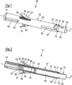
- Fig. 1 shows a cylindrical applicator 10.
- the applicator 10 comprises a housing 12 that has a substantially tubular shape.
- One end of the housing 12 is terminated by an application tip 14.
- the end bordering the application tip 14 will in the following be termed "distal", since in normal operation it is distal from the person using the applicator 10.
- the housing 12 comprises a proximal end having an opening 16 in which an insert 18 is introduced. Via the opening 16 the insert 18 is inserted into the tube-like inside of the housing 12, which can be considered a receiving portion 19 of the housing.
- the insert 18 comprises a cylindrical shape and can be inserted into the housing 12 along a displacement axis D.
- the insert 18 comprises two retaining portions 20 arranged at opposite sides of the outer surface of the insert (only one is visible in Fig. 1 ).
- the retaining portions 20 are shaped wedge-like, i.e. they comprise a ramp that diminishes towards the distal end.
- the retaining portions 20 When the insert 18 is inserted into the housing 12 the retaining portions 20 first pass through two notches 21 and then snap into circumferential sections 22 of guide slots 24 (only one of the circumferntial sections 22 and the guide slots 24 are visible in Fig. 1 ), wherein a further displacement of the insert along the displacement axis is prevented by the retaining portions 20 abutting against the borders of the circumferential sections 22.
- the housing 12 comprises two levers 26 which are hingedly attached to an outer wall 28 of the housing.
- the levers 26 are made from a flexible material and further comprise two pawls 30.
- each lever 26 sticks out from the housing 12, i.e. forms an angle of about 20° to 40° with the displacement axis D.
- the pawl 30 is inclined toward the displacement axis D and is abutting against a rack of teeth 32 which is arranged at the outer surface of the insert 18.
- the lever 26, the pawl 30 and the rack of teeth 32 form a ratchet mechanism.
- the rack of teeth 32 is arranged circumferential at the outer surface of the insert 18. Alternatively, a plurality of racks can be provided at the insert 18.
- a lever-cut-out 27 is provided in the outer surface of the housing.
- the lever-cut-out 27 allows the pawl 30 to engage with the rack of teeth 32.
- Fig. 1 shows the applicator 10 in a locked position.
- a grip portion 23 of the insert 18 is outside the housing 12, if the applicator is in the locked state.
- the insert 18 In order to transition the applicator 10 into an unlocked state, the insert 18 has to be rotated relative to the housing 12 such that the retaining portions 20 travel along the circumferential sections 22 until they reach two longitudinal sections 34 (only one is shown) of the guide slots 24.
- the circumferential sections 22 each comprise an angle ⁇ of about 70° with the respective longitudinal section 34. Due to the angle ⁇ , the insert 18 is moved further inside the housing 12, when the insert 18 is rotated from the locked into the unlocked position.
- Fig. 2 shows the applicator 10 in the locked position in a cross-sectional view such that the inside of the housing 12 and the insert 18 is visible.
- a container 36 for flowable component e.g. a fluid, a gel or the like or a mixture such as a medical, dental, pharmaceutical, cosmetic, adhesive or veterinary preparation
- a sealing film 38 which is made from a pierceable material.
- a piercing tip 40 of the housing 12 extends into the inside of the insert 18.
- the piercing tip 40 has a bullet-like shape, as can be seen in greater detail in Fig. 5 .
- an inlet to a central fluid channel 42 is provided. If flowable component flows from the container 36 through the fluid channel 42 it reaches a transmission volume 44 inside the piercing tip 40.
- the material of the application tip 14 extends into the transmission volume 44 such that the fluid component can enter the material of the application tip 14 in the transmission volume 44.
- the application tip 14 can be made from a soft or porous material.
- the container 36 comprises the same bullet-like shape as the piercing tip 40 and is thereby adapted to receive the piercing tip 40.
- Figs. 3 and 4 show the applicator 10 in an initial unlocked state, wherein the retaining portion 20 is situated in the longitudinal section 34 of the guide slot 24.
- the insert 18 has slightly advanced along the displacement axis D in the direction of the distal end of the applicator 10.
- the piercing tip 40 pierced the sealing film 38 such that a fluid connection between the flowable component in the container 36 and the fluid channel 42 inside the piercing tip 40 is established.
- the levers 26 are operated, i.e. pinched toward the insert 18.
- the pawls 30 engage with the rack of teeth 32 and advance the insert 18 further into the housing 12.
- the insert 18 is then displaced along the displacement axis D.
- the piercing tip 40 advances further inside the container 36 thereby reducing the volume of the container 36.
- the flowable component stored inside the container 36 is then pressed through the fluid channel 42 and led to the application tip 14. Since every operation of the levers 26 displaces the insert 18 by approximately the same length along the displacement axis D, every operation of the levers 26 yields the same amount of flowable component that is ejected.
- the rack of teeth 32 abuts against two clicks 46 that are shown in Fig. 5 .
- the clicks 46 prevent a backwards movement of the insert 18.
- the rack of teeth 32 becomes visible through an indicator cut out 48.
- the indicator cut out 48 provides a user with information about how much component is left in the container 36.
- the insert 18 When the applicator 10 is operated, first the insert 18 is inserted into the housing 12. The retaining portions 20 are thereby caught in the circumferential sections 20 of the guide slots 24, i.e. the applicator 10 is in the locked state. The insert 18 is then rotated by approximately 90° relative to the housing 12 thus transitioning the applicator 10 into the unlocked state.
- the levers 26 are repeatedly pinched towards the insert 18, whereby the insert 18 is displaced in the direction of the distal end of the housing 12.
- the displacement is effected by the pawls 30 engaging with the rack of teeth 32.
- the levers 26 are released, they return to their initial position, thereby moving the pawls 30 in the direction of the proximal end of the housing.
- the levers 26 can be operated in the same manner again until the container 36 is empty.
- Fig. 6 shows the applicator 10 in an emptied state, i.e. the container 36 does not contain flowable component anymore but is fully filled with the piercing tip 40.
- the insert 18 abuts against the distal end of the housing 12.
Landscapes
- Engineering & Computer Science (AREA)
- Health & Medical Sciences (AREA)
- Mechanical Engineering (AREA)
- Life Sciences & Earth Sciences (AREA)
- Surgery (AREA)
- Animal Behavior & Ethology (AREA)
- General Health & Medical Sciences (AREA)
- Heart & Thoracic Surgery (AREA)
- Biomedical Technology (AREA)
- Veterinary Medicine (AREA)
- Public Health (AREA)
- Physics & Mathematics (AREA)
- Nuclear Medicine, Radiotherapy & Molecular Imaging (AREA)
- Molecular Biology (AREA)
- Medical Informatics (AREA)
- Fluid Mechanics (AREA)
- General Physics & Mathematics (AREA)
- Anesthesiology (AREA)
- Hematology (AREA)
- Coating Apparatus (AREA)
- Containers And Packaging Bodies Having A Special Means To Remove Contents (AREA)
- Infusion, Injection, And Reservoir Apparatuses (AREA)
Abstract
The present invention relates to an applicator (10) for ejecting doses of a flowable component, comprising
- a housing (12),
- an application tip (14) connected to the housing (12),
- an actuation mechanism (26, 30), and
- an insert (18) which is detachable from the housing (12), the insert (18) being adapted to be inserted into the housing (12), the insert (18) having a storage volume (36) for the flowable component, wherein the housing (12) comprises a receiving portion (19) adapted to the insert (18).
- a housing (12),
- an application tip (14) connected to the housing (12),
- an actuation mechanism (26, 30), and
- an insert (18) which is detachable from the housing (12), the insert (18) being adapted to be inserted into the housing (12), the insert (18) having a storage volume (36) for the flowable component, wherein the housing (12) comprises a receiving portion (19) adapted to the insert (18).
The applicator is characterized in that the insert (18) comprises a drive portion (32) which is adapted to cooperate with the actuation mechanism (26, 30) so that the operation of the actuation mechanism (26, 30) results in a displacement of the insert (18) relative to the housing (12) and on a displacement axis (D).
Description
- The present invention relates to an applicator for ejecting doses of a flowable component, the applicator comprising a housing, an application tip connected to the housing, an actuation mechanism and an insert which is detachable from the housing, the insert being adapted to be inserted into the housing, the insert having a storage volume for the flowable component. The housing comprises a receiving portion adapted to the insert.
- Applicators are known in the prior art that permit the dispensing of flowable components, such as adhesives or other substances. The substances can, for example, be used in medical applications for wound care or in DIY applications for sealing and/or bonding purposes. Common to at least these two types of applications is the use of cyanoacrylate (CA). CA is a fast setting adhesive particularly when it is in contact with water. Humidity in air can also cause the CA to set. For this reason CA has to be stored in a sealed air-tight container.
- Some applications therefore use glass ampules as a storage container. Glass ampules provide an air-tight seal. However, in use a part of the glass ampule is broken off, such that the possibility exists that miniscule glass splinters remain in the CA, which would also be dispensed at the position of application of the CA. This should in particular be avoided having regard to medical applications.
- Moreover, a targeted dispensing from a glass ampule is not generally possible via the broken off end. Other applications use plastic applicators in which the CA is sealed in a compartment. Particularly, the CA can be stored in an insert for the applicator. The applicator then provides an ejection mechanism, e.g. a plunger that is adapted to move a piston of the insert. When moved, the piston of the insert reduces the storage volume and thereby ejects the CA.
- The handling of such applicators can be laborious since prior to inserting the insert, the plunger has to be brought into a retracted position. After the insertion of the insert, the plunger has to be adapted to the position of the insert, i.e. the plunger has to be brought in a starting position. In the retracted position and the starting position the plunger often stands out from the housing of the applicator, thus, further impairing an easy handling of the applicator.
- In view of the foregoing it is an object of the present invention to provide an applicator which allows an easy handling and at the same time can be manufactured in an economic manner. It is a further object of the invention to provide an applicator which allows ejecting doses of a constant volume.
- These objects are achieved by an applicator having the features of claim 1.
- Particularly, these objects are satisfied by an applicator having an insert which comprises a drive portion which is adapted to cooperate with the actuation mechanism so that the operation of the actuation mechanism results in a displacement of the insert relative to the housing along a displacement axis.
- The invention is based on the finding that the handling of an applicator can be improved if the insert itself is moved relative to the housing in order to eject or dispense the flowable component. Particularly, the insert can be moved in its entirety.
- The applicator therefore does not require a plunger or a drive mechanism which is substantially completely arranged at the housing of the applicator. Rather, the insert comprises parts of such a drive mechanism, namely the drive portion. Thereby the need to operate or to move the drive mechanism before inserting the insert into the housing is eliminated. Since the insert comprises parts of the drive mechanism, i.e. the drive portion, by inserting the insert into the receiving portion of the housing the drive portion is automatically set up for operation.
- In other words, the steps required by applicators of the prior art, namely (1) moving the drive mechanism into a retracted position, (2) inserting the insert into the housing and (3) moving the drive mechanism into a starting position are no longer necessary. Instead, the insert only has to be placed in the housing. After this single step of preparation of the applicator, the applicator can then be ready for use. The inventive applicator thus dramatically reduces the handling effort for its operation.
- Further, the actuation mechanism can be advantageously provided at the housing, whereas the drive portion is arranged at the insert. This separated drive mechanism can be manufactured in a simple and economic process, thereby reducing the costs for the production of the applicator.
- It is to be noted that the term "arranged at" includes "adjacent to", "comprises" and "directly connected to". As an example, the actuation mechanism can either be directly connected to the housing (and preferably be integral with the housing) or be arranged adjacent to the housing. The housing may also comprise the actuation mechanism.
- After the insert is received in the receiving portion of the housing, the actuation mechanism can be operated, whereby the actuation mechanism cooperates with the drive portion. This cooperation leads to a displacement of the insert relative to the housing along the displacement axis. The displacement of the insert can eject a dose of the flowable component through the application tip. Subsequent operations of the actuation mechanism displace or move the insert incrementally along the displacement axis. The incremental movements can have the same step width. The displacement axis can form the center of the applicator, i.e. the applicator can be substantially symmetrical with respect to the displacement axis.
- Preferably the applicator is configured such that at least two subsequent operations of the actuation mechanism result in displacement of the insert relative to the housing along the displacement axis. A stepwise application or ejection of the flowable component is therefore possible. Advantageously a plurality of subsequent operations of the actuation mechanism can be performed, wherein each operation substantially ejects the same volume of flowable component. It is thus possible to eject the flowable component in small doses. Hence, the applicator can be used in applications that require very small doses or a repeatable ejection of a component.
- Advantageously the actuation mechanism and the drive portion are configured to allow and/or effect only a displacement of the insert in one direction along the displacement axis. The displacement can only be effected in the direction toward the application tip. A backwards movement can be blocked. Thereby it is prohibited that e.g. air or humidity is sucked into the storage volume. Air or humidity could deteriorate the flowable component stored in the storage volume.
- It is preferred that the actuation mechanism and/or the drive portion comprise a ratchet mechanism. The ratchet mechanism may only allow and/or effect a displacement of the insert in one direction along the displacement axis.
- Preferably the actuation mechanism comprises at least one pawl and/or the drive portion comprises at least one rack of teeth. The pawl and the teeth form the ratchet mechanism. The pawl can also be termed a click. The pawl is advantageously arranged at the housing or connected to the housing, whereas the teeth are arranged at the insert. Particularly, the teeth can be arranged at an outer surface of the insert and can be arranged along the direction of the displacement axis.
- Advantageously the actuation mechanism comprises a lever that is elastically bendable with respect to the housing, wherein the pawl is arranged at the lever. By operating the lever a force can be generated, whereby the pawl presses against the teeth and displaces the insert. Since the lever is elastically bendable, the lever can move back to its initial position after being released. When moving back to its initial position, the lever can also move the pawl "backwards", i.e. opposite the direction of displacement of the insert, wherein the pawl can then engage with the rack of teeth, again. The pawl can then displace the insert, again.
- The lever can be forked, wherein one branch of the fork can comprise the pawl. The other branch can be configured as a gripping portion that allows the lever to be operated manually. The gripping portion may be formed at the end of the lever.
- The lever can be hingedly attached at the housing, wherein the lever can pivot around the hinge. The pawl can be arranged closer to the hinge than an end of the lever without the hinge. In other words, the branch with the gripping portion may have a longer lever than the branch comprising the pawl. Thereby a force applied to the gripping portion can be amplified by the lever. A displacement of the insert and an ejection of a dose of component can then be facilitated without the need for excessive force.
- Advantageously the lever may stick out from the housing. The housing may have a cutout for the rack of teeth of the insert. The pawl can then be arranged such that it reaches the teeth through the cutout.
- Preferably the housing is made from a single material and is particularly formed as a single piece. Further, the levers and the housing can be formed integrally. In particular, the housing and/or the levers can be manufactured in an injection molding process.
- More preferably the housing comprises a further pawl that is adapted to engage with the at least one rack of teeth. The further pawl may not be operated manually but be fixedly arranged at the housing. The further pawl can impede a backwards movement of the insert.
- In this connection it should be noted that the further pawl may be arranged at a different rotational position with respect to the longitudinal axis compared to the pawl of the actuation mechanism. To allow the further pawl to engage with the at least one rack of teeth, the rack of teeth can preferably be arranged at the whole circumference or surface of the insert. The rack of teeth may therefore be at least partly circumferential to the insert. Alternatively the insert may comprise several racks of teeth, preferably four racks of teeth. An angle of 90° (if seen in the direction of the displacement axis) may be defined between two adjacent racks.
- The applicator advantageously comprises a further actuation mechanism and a further drive portion, the further actuation mechanism and the further drive portion being preferably arranged opposite the actuation mechanism and the drive portion with respect to the displacement axis. In other words, the applicator may comprise at least two ratchet mechanisms. These ratchet mechanisms can be provided symmetrically with respect to the displacement axis. Both ratchet mechanisms can be substantially identical or corresponding to each other. Generally, the actuation mechanism and the further actuation mechanism as well as the drive portion and the further drive portion may correspond to each other.
- The applicator may therefore have two levers which allow an easy operation with one hand, by pinching the two levers together. The two levers may stand off from the housing and therefore can appear to be wings that can be pinched together to eject one dose or drop of the flowable component.
- Preferably, the housing and/or the insert comprise a substantially cylindrical shape. Such a cylindrical shape can easily be held in one hand, thereby further improving the handling of the applicator. The housing may be a hollow cylinder or a tube. The receiving portion may be the space inside the tube. Advantageously, the insert can also have a cylindrical form, wherein the outer diameter of the insert corresponds substantially to the inner diameter of the housing. A cylindrical housing and insert bear the advantage that the insert can be inserted in the housing independent of its rotational position with respect to the displacement axis. This additionally facilitates an easy handling of the applicator.
- It is preferred that the storage volume is sealed with a pierceable material, particularly a pierceable film or foil. The storage volume can have a substantially cylindrical shape, wherein one base of the cylinder can be sealed with the pierceable material (the seal or sealing film). The cylinder surface can be the outer wall of the insert. The further base of the cylinder is made from a non-pierceable material.
- A pierceable material is e.g. a material that can be penetrated with a sharp tip or edge. A sharp tip or edge may have a maxiumum dimension at its respective end of less than 1 mm. Even if penetrated, the pierceable material preferably will only get punctured at the site of piercing. This means, the pierceable material will advantageously not shatter or break at positions other than the position of the piercing. The pierceable material further advantageously has water and/or oxygen barrier properties.
- The pierceable material can be formed by a flexible plastic, polymer and/or aluminum film. Further, the pierceable material can comprise polyolefin, cyclo-olefin-copolymer (COC), ethylene vinyl alcohol (EVOH), polyamide and/or polyester. Preferably the pierceable material is a multilayer film, e.g. comprising one layer of aluminum and one layer of polyolefin or cyclo-olefin-copolymer (COC). The thickness of the pierceable material can be in the range of 10 µm to 100 µm. Preferably the thickness is in the range of 30 µm to 70 µm. Advantageously the thickness is 50 µm.
- Advantageously the housing comprises a piercing tip adapted to pierce the pierceable material, when the insert is displaced along the displacement axis. Upon a first displacement of the insert, the piercing tip "opens" the storage volume (by puncturing the pierceable material) thus allowing the ejection of the flowable component. The piercing tip and the application tip can be fluidly connected. Particularly, the piercing tip may comprise a fluid passage for the flowable component that can be formed as a central channel in the piercing tip.
- After piercing of the seal of the storage volume the flowable component may then flow through the piercing tip to the application tip and can then be ejected from the application tip. Apart from the piercing necessary to allow a fluid connection, the piercing tip can be designed to seal the storage volume. Thereby a dripping of the flowable component can be prevented.
- Preferably, the application tip can be made of or comprise a soft, flexible and/or porous material.
- It is advantageous, if an end region of the storage volume is adapted to the shape of the piercing tip. The storage volume can have a bullet-shape in a cross-sectional view. Due to the adapted shape of the piercing tip and the storage volume, the storage volume can be emptied almost completely, since the piercing tip can displace the flowable component nearly in its entirety.
- It is preferable, if the applicator can be transitioned from a locked state to an unlocked state. The transition can be achieved by rotating the insert relative to the housing. In the locked state displacement of the insert relative to the housing along the displacement axis is substantially prevented and in the unlocked state displacement of the insert relative to the housing along the displacement axis is permitted. The applicator can thus comprise a safety function which prevents an unintentional ejection of the flowable component. To allow the ejection of the flowable component, a turning movement has to be applied to the insert of the applicator in order to unlock the applicator. The turning movement can be a rotation around the displacement axis.
- In order to allow an easy gripping of the insert for the turning movement, the insert can comprise a grip portion. The grip portion is preferably arranged at an end of the insert. The grip portion may stick out from the housing after the insert is initially received in the receiving portion of the housing. To unlock the applicator, the applicator may be held at the housing and at the grip portion of the insert thus allowing a twisting or a rotation of the insert relative to the housing. After the rotation of the insert the applicator is in the unlocked state and can be used to eject doses of the flowable component.
- Preferably the rotation of the insert into the unlocked state leads to a displacement of the insert relative to the housing along the displacement axis, wherein the piercing tip pierces the pierceable material. The rotation of the insert thus not only unlocks the applicator but also leads to a defined movement of the insert along the displacement axis. The movement along the displacement axis causes the piercing tip to pierce e.g. the sealing film or foil of the storage volume. Thereby the handling of the applicator is further simplified since one movement, namely the rotation to unlock the applicator, also leads to the "opening" of the storage volume. This means that after the unlocking of the applicator, the first operation of the actuation mechanism will directly lead to the ejection of a first dose of the flowable component.
- Advantageously, the insert comprises at least one retaining portion engaging with the housing, whereby a removal of the insert from the housing is prevented, wherein the housing preferably comprises a guide slot for engaging with the retaining portion, the guide slot having a section being substantially circumferential to the displacement axis, and a longitudinal section being substantially parallel to the displacement axis. The retaining portion may have a wedged shape in order to allow a smooth inserting of the insert into the housing. To facilitate an easy insertion, the housing may additionally comprise at least one notch at an end opposite of the application tip. When the insert is inserted into the housing, the retaining portion can be guided by the notch. The notch can extend in the direction of the displacement axis.
- After the insert has reached its initial position in the receiving portion, a withdrawal of the insert can be prevented as the retaining portion may be abutting against the guide slot. The guide slot and the retaining portion may further prevent that the insert is unintentionally inserted too deep into the housing, which would lead to the piercing of the sealing film and the uncontrollable ejection of the flowable component. This can be prevented by catching the retaining portion in the circumferential section of the guide slot.
- Once the insert is inserted into the housing, due to the retaining portion the insert cannot be removed without the application of undue force. The applicator can therefore be a single-use applicator.
- The circumferential section may span approximately 90° of the circumference of the housing. The circumferential section can have an angle of less than 90° with the displacement axis (when viewed in a projection to a plane comprising the displacement axis). The angle of less than 90° with the displacement axis can lead to a displacement of the insert along the displacement axis if the retaining portion is moved along the circumferential section. The retaining portion can be moved along the circumferential section if the insert is rotated relative to the housing, i.e. when the applicator is brought from the locked state into the unlocked state. The angle of smaller than 90° can thereby assure that the storage volume is opened by the piercing tip, when the applicator is brought into the unlocked state.
- In the initial unlocked state the retaining portion can be positioned at a first end of the longitudinal section of the guide slot. Every operation of the actuation mechanism which leads to a displacement of the insert along the displacement axis also displaces the retaining portion along the displacement axis. This displacement leads to a movement of the retaining portion in the longitudinal section of the guide slot. The longitudinal section of the guide slot can be configured such that the retaining portion abuts against a second end of the longitudinal section when the flowable component is completely ejected.
- Further advantageously a marker area (e.g. a colored area) is provided at the insert. Additionally the housing can comprise a cutout for the marker area, wherein more and more of the marker area can become visible as the insert advances into the housing. Particularly, the rack of teeth can be the marker area and is preferably provided with a color different from the remaining surface of the insert. The rack of teeth can become visible in the marker area upon ejection of doses of the flowable component. The cutout for the marker area may comprise or may be bordered by a click that engages with the rack of teeth and thereby prevents a backwards movement of the insert.
- With respect to the displacement axis, the hinges of the levers can be arranged between the marker area and the guide slot.
- Advantageously the storage volume is filled with the flowable component, the flowable component preferably being cyanoacrylate. The insert can thus be a cartridge comprising the flowable component.
- Preferably the applicator described in the foregoing is used in the treatment of a patient, for example by applying or dispensing CA to the skin of a human. By applying CA to the skin, e.g. bed sores can be treated.
- The invention further relates to a method of ejecting or dispensing doses of a flowable component, using an applicator of the kind described in the foregoing, the method comprising:
- inserting an insert into a housing of an applicator,
- operating an actuation mechanism to displace the insert relative to the housing along a displacement axis, thereby ejecting a dose of flowable component from a storage volume of the insert through an application tip.
- Preferably, prior to operating the actuation mechanism, the insert and the housing are rotated relative to another in order to transition the applicator from a locked state into an unlocked state.
- Advantageously operating the actuation mechanism is repeated a plurality of times to eject or dispense a plurality of doses of flowable component.
- The invention also relates to an insert for an applicator of the kind described above. The insert comprises a drive portion for engaging with an actuation mechanism and a storage volume, the storage volume comprising a flowable component.
- Additionally the invention also relates to a housing for an applicator of the kind described above. The housing comprises an actuation mechanism and a receiving portion for an insert. The actuation mechanism is configured to cooperate with a drive portion of the insert.
- The housing and the insert can both be made by injection molding.
- Furthermore, the invention relates to a kit of parts for ejecting doses of a flowable component, comprising a housing with an actuation mechanism and an insert with a drive portion. The insert is formed such that it can be inserted into a receiving portion of the housing. The insert can comprise a storage volume for or with the flowable component.
- The advantages, preferable features and embodiments of the inventive applicator described in the foregoing also apply to the inventive method, the inventive insert, the inventive housing and the inventive kit of parts.
- Further embodiments of the invention are described in the following description of the Figures. The invention will be explained in the following in detail by means of exemplary embodiments and with reference to the drawings in which is shown:
- Fig. 1
- an applicator in a locked state;
- Fig. 2
- the applicator of
Fig. 1 in a cross-sectional view; - Fig. 3
- the applicator of
Fig. 1 in an unlocked state; - Fig. 4
- the applicator of
Fig. 3 in a cross-sectional view; - Fig. 5
- a detailed view of a piercing tip and an application tip; and
- Fig. 6
- a cross-sectional view of an emptied applicator.
- In the following the same reference numerals will be used for parts having the same or equivalent function. Any statement made having regard to the direction of a component are made relative to the position shown in the drawing and can naturally vary in the actual position of application.
-
Fig. 1 shows acylindrical applicator 10. Theapplicator 10 comprises ahousing 12 that has a substantially tubular shape. One end of thehousing 12 is terminated by anapplication tip 14. The end bordering theapplication tip 14 will in the following be termed "distal", since in normal operation it is distal from the person using theapplicator 10. Opposite the distal end, thehousing 12 comprises a proximal end having anopening 16 in which aninsert 18 is introduced. Via theopening 16 theinsert 18 is inserted into the tube-like inside of thehousing 12, which can be considered a receivingportion 19 of the housing. - The
insert 18 comprises a cylindrical shape and can be inserted into thehousing 12 along a displacement axis D. Theinsert 18 comprises two retainingportions 20 arranged at opposite sides of the outer surface of the insert (only one is visible inFig. 1 ). The retainingportions 20 are shaped wedge-like, i.e. they comprise a ramp that diminishes towards the distal end. - When the
insert 18 is inserted into thehousing 12 the retainingportions 20 first pass through twonotches 21 and then snap intocircumferential sections 22 of guide slots 24 (only one of thecircumferntial sections 22 and theguide slots 24 are visible inFig. 1 ), wherein a further displacement of the insert along the displacement axis is prevented by the retainingportions 20 abutting against the borders of thecircumferential sections 22. - The
housing 12 comprises twolevers 26 which are hingedly attached to anouter wall 28 of the housing. Thelevers 26 are made from a flexible material and further comprise twopawls 30. - In its normal position, each
lever 26 sticks out from thehousing 12, i.e. forms an angle of about 20° to 40° with the displacement axis D. Thepawl 30 is inclined toward the displacement axis D and is abutting against a rack ofteeth 32 which is arranged at the outer surface of theinsert 18. - The
lever 26, thepawl 30 and the rack ofteeth 32 form a ratchet mechanism. - The rack of
teeth 32 is arranged circumferential at the outer surface of theinsert 18. Alternatively, a plurality of racks can be provided at theinsert 18. - Beneath each
lever 26, a lever-cut-out 27 is provided in the outer surface of the housing. The lever-cut-out 27 allows thepawl 30 to engage with the rack ofteeth 32. -
Fig. 1 shows theapplicator 10 in a locked position. Agrip portion 23 of theinsert 18 is outside thehousing 12, if the applicator is in the locked state. As the retainingportions 20 are received in thecircumferential sections 22 of the guide slots 24 a movement along the displacement axis D is substantially prohibited. Thus, even operation of thelevers 26 would not move theinsert 18 along the displacement axis D. - In order to transition the
applicator 10 into an unlocked state, theinsert 18 has to be rotated relative to thehousing 12 such that the retainingportions 20 travel along thecircumferential sections 22 until they reach two longitudinal sections 34 (only one is shown) of theguide slots 24. - The
circumferential sections 22 each comprise an angle α of about 70° with the respectivelongitudinal section 34. Due to the angle α, theinsert 18 is moved further inside thehousing 12, when theinsert 18 is rotated from the locked into the unlocked position. -
Fig. 2 shows theapplicator 10 in the locked position in a cross-sectional view such that the inside of thehousing 12 and theinsert 18 is visible. - Inside the insert 18 a
container 36 for flowable component (e.g. a fluid, a gel or the like or a mixture such as a medical, dental, pharmaceutical, cosmetic, adhesive or veterinary preparation) is arranged at a distal end of theinsert 18. At its distal end thecontainer 36 is sealed by a sealingfilm 38 which is made from a pierceable material. - In the locked state, adjacent to the sealing film 38 a piercing
tip 40 of thehousing 12 extends into the inside of theinsert 18. The piercingtip 40 has a bullet-like shape, as can be seen in greater detail inFig. 5 . At the center of the piercing tip an inlet to acentral fluid channel 42 is provided. If flowable component flows from thecontainer 36 through thefluid channel 42 it reaches atransmission volume 44 inside the piercingtip 40. The material of theapplication tip 14 extends into thetransmission volume 44 such that the fluid component can enter the material of theapplication tip 14 in thetransmission volume 44. Theapplication tip 14 can be made from a soft or porous material. - Coming back to
Fig. 2 , it can be seen that thecontainer 36 comprises the same bullet-like shape as the piercingtip 40 and is thereby adapted to receive the piercingtip 40. - Turning now to
Figs. 3 and 4 which show theapplicator 10 in an initial unlocked state, wherein the retainingportion 20 is situated in thelongitudinal section 34 of theguide slot 24. Compared toFigs. 1 and 2 , inFigs. 3 and 4 , theinsert 18 has slightly advanced along the displacement axis D in the direction of the distal end of theapplicator 10. Thereby, the piercingtip 40 pierced the sealingfilm 38 such that a fluid connection between the flowable component in thecontainer 36 and thefluid channel 42 inside the piercingtip 40 is established. - In the unlocked state the
levers 26 are operated, i.e. pinched toward theinsert 18. Thereby, thepawls 30 engage with the rack ofteeth 32 and advance theinsert 18 further into thehousing 12. In other words, theinsert 18 is then displaced along the displacement axis D. Due to the displacement, the piercingtip 40 advances further inside thecontainer 36 thereby reducing the volume of thecontainer 36. In consequence, the flowable component stored inside thecontainer 36 is then pressed through thefluid channel 42 and led to theapplication tip 14. Since every operation of thelevers 26 displaces theinsert 18 by approximately the same length along the displacement axis D, every operation of thelevers 26 yields the same amount of flowable component that is ejected. - When the
insert 18 moves inside thehousing 12, the rack ofteeth 32 abuts against twoclicks 46 that are shown inFig. 5 . Theclicks 46 prevent a backwards movement of theinsert 18. At the same time, when theinsert 18 moves further inside thehousing 12, the rack ofteeth 32 becomes visible through an indicator cut out 48. The indicator cut out 48 provides a user with information about how much component is left in thecontainer 36. - When the
applicator 10 is operated, first theinsert 18 is inserted into thehousing 12. The retainingportions 20 are thereby caught in thecircumferential sections 20 of theguide slots 24, i.e. theapplicator 10 is in the locked state. Theinsert 18 is then rotated by approximately 90° relative to thehousing 12 thus transitioning theapplicator 10 into the unlocked state. - In the unlocked state the
levers 26 are repeatedly pinched towards theinsert 18, whereby theinsert 18 is displaced in the direction of the distal end of thehousing 12. The displacement is effected by thepawls 30 engaging with the rack ofteeth 32. When thelevers 26 are released, they return to their initial position, thereby moving thepawls 30 in the direction of the proximal end of the housing. After thelevers 26 have returned to their initial position, thelevers 26 can be operated in the same manner again until thecontainer 36 is empty. -
Fig. 6 shows theapplicator 10 in an emptied state, i.e. thecontainer 36 does not contain flowable component anymore but is fully filled with the piercingtip 40. In the emptied state theinsert 18 abuts against the distal end of thehousing 12. -
- 10
- applicator
- 12
- housing
- 14
- application tip
- 16
- opening
- 18
- insert
- 19
- receiving portion
- 20
- retaining portion
- 21
- notch
- 22
- circumferential section
- 23
- grip portion
- 24
- guide slot
- 26
- lever
- 27
- lever-cut-out
- 28
- outer wall
- 30
- pawl
- 32
- rack of teeth
- 34
- longitudinal section
- 36
- container
- 38
- sealing film
- 40
- piercing tip
- 42
- fluid channel
- 44
- transmission volume
- 46
- click
- 48
- indicator cut out
- D
- displacement axis
- α
- angle
Claims (15)
- An applicator (10) for ejecting doses of a flowable component, comprising- a housing (12),- an application tip (14) connected to the housing (12),- an actuation mechanism (26, 30), and- an insert (18) which is detachable from the housing (12), the insert (18) being adapted to be inserted into the housing (12), the insert (18) having a storage volume (36) for the flowable component, whereincharacterized in that
the housing (12) comprises a receiving portion (19) adapted to the insert (18),
the insert (18) comprises a drive portion (32) which is adapted to cooperate with the actuation mechanism (26, 30) so that the operation of the actuation mechanism (26, 30) results in a displacement of the insert (18) relative to the housing (12) along a displacement axis (D). - The applicator (10) of claim 1, wherein
the applicator (10) is configured such that at least two subsequent operations of the actuation mechanism (26, 30) result in displacements of the insert (18) relative to the housing (12) along the displacement axis (D). - The applicator (10) of at least one of claims 1 or 2, wherein
the actuation mechanism (26, 30) and/or the drive portion (32) comprises a ratchet mechanism. - The applicator (10) of at least one of the previous claims, wherein
the actuation mechanism (26, 30) comprises at least one pawl and/or the drive portion (32) comprises at least one rack of teeth. - The applicator (10) of claim 4, wherein
the actuation mechanism (26, 30) comprises a lever that is elastically bendable with respect to the housing (12), wherein the pawl is arranged at the lever. - The applicator (10) of at least one of the previous claims, further comprising a further actuation mechanism (26, 30) and a further drive portion (32), the further actuation mechanism (26, 30) and the further drive portion (32) being preferably arranged opposite the actuation mechanism (26, 30) and the drive portion (32) with respect to the displacement axis (D).
- The applicator (10) of at least one of the previous claims, wherein
the storage volume (36) is sealed with a pierceable material (38), particularly a pierceable film or foil. - The applicator (10) of claim 7, wherein
the housing (12) comprises a piercing tip (40) adapted to pierce the pierceable material (38), when the insert (18) is displaced along the displacement axis (D). - The applicator (10) of claim 8, wherein
an end region of the storage volume (36) is adapted to the form of the piercing tip (40). - The applicator (10) of at least one of the previous claims, wherein
the applicator (10) can be transitioned from a locked state to an unlocked state by rotation of the insert (18) relative to the housing (12), wherein in the locked state displacement of the insert (18) relative to the housing (12) along the displacement axis (D) is substantially prevented and in the unlocked state displacement of the insert (18) relative to the housing (12) along the displacement axis (D) is permitted. - The applicator (10) of claims 8 and 10, wherein
rotation of the insert (18) into the unlocked state leads to a displacement of the insert (18) relative to the housing along the displacement axis (D), wherein the piercing tip (40) pierces the pierceable material. - The applicator (10) of at least one of the previous claims, wherein
the insert (18) comprises a retaining portion (20) engaging with the housing (12), whereby a removal of the insert (18) from the housing (12) is prevented, wherein
the housing (12) preferably comprises a guide slot (24) for engaging with the retaining portion (20), the guide slot (24) having a circumferential section (22) being substantially circumferential to the displacement axis (D), and a longitudinal section (34) being substantially parallel to the displacement axis (D). - The applicator (10) of at least one of the previous claims, wherein
the storage volume (36) is filled with the flowable component, the flowable component preferably being cyanoacrylate. - An insert (18) for an applicator (10) in accordance with at least one of the previous claims, comprising- a drive portion (32) for engaging with an actuation mechanism (26, 30) and- a storage volume (36), the storage volume (36) comprising a flowable component.
- A method of ejecting a flowable component, using an applicator (10) in accordance with at least one of claims 1 to 13, comprising:- inserting an insert (18) into a housing (12) of the applicator (10),- operating an actuation mechanism (26, 30) to displace the insert relative to the housing (12) along a displacement axis (D), thereby ejecting a dose of flowable component from a storage volume (36) of the insert (18) through an application tip (14).
Priority Applications (7)
| Application Number | Priority Date | Filing Date | Title |
|---|---|---|---|
| EP15186916.1A EP3147034A1 (en) | 2015-09-25 | 2015-09-25 | Applicator for ejecting doses of a flowable component |
| US15/762,753 US10486189B2 (en) | 2015-09-25 | 2016-09-26 | Applicator for ejecting doses of a flowable component |
| PCT/EP2016/072879 WO2017051039A1 (en) | 2015-09-25 | 2016-09-26 | Applicator for ejecting doses of a flowable component |
| JP2018515464A JP2018532475A (en) | 2015-09-25 | 2016-09-26 | Applicator for releasing multiple doses of flowable components |
| CN201680055681.9A CN108348947A (en) | 2015-09-25 | 2016-09-26 | Applicator for the flowable component for spraying multiple dosage |
| BR112018005829A BR112018005829A2 (en) | 2015-09-25 | 2016-09-26 | applicator for ejecting doses of a dispersible component |
| EP16775156.9A EP3328556B1 (en) | 2015-09-25 | 2016-09-26 | Applicator for ejecting doses of a flowable component |
Applications Claiming Priority (1)
| Application Number | Priority Date | Filing Date | Title |
|---|---|---|---|
| EP15186916.1A EP3147034A1 (en) | 2015-09-25 | 2015-09-25 | Applicator for ejecting doses of a flowable component |
Publications (1)
| Publication Number | Publication Date |
|---|---|
| EP3147034A1 true EP3147034A1 (en) | 2017-03-29 |
Family
ID=54207357
Family Applications (2)
| Application Number | Title | Priority Date | Filing Date |
|---|---|---|---|
| EP15186916.1A Withdrawn EP3147034A1 (en) | 2015-09-25 | 2015-09-25 | Applicator for ejecting doses of a flowable component |
| EP16775156.9A Active EP3328556B1 (en) | 2015-09-25 | 2016-09-26 | Applicator for ejecting doses of a flowable component |
Family Applications After (1)
| Application Number | Title | Priority Date | Filing Date |
|---|---|---|---|
| EP16775156.9A Active EP3328556B1 (en) | 2015-09-25 | 2016-09-26 | Applicator for ejecting doses of a flowable component |
Country Status (6)
| Country | Link |
|---|---|
| US (1) | US10486189B2 (en) |
| EP (2) | EP3147034A1 (en) |
| JP (1) | JP2018532475A (en) |
| CN (1) | CN108348947A (en) |
| BR (1) | BR112018005829A2 (en) |
| WO (1) | WO2017051039A1 (en) |
Cited By (1)
| Publication number | Priority date | Publication date | Assignee | Title |
|---|---|---|---|---|
| EP3599031A1 (en) * | 2018-07-26 | 2020-01-29 | Sulzer Mixpac AG | Discharger, container, dispensing part, activation part and method of assembling and using a discharger |
Families Citing this family (8)
| Publication number | Priority date | Publication date | Assignee | Title |
|---|---|---|---|---|
| EP3518821A1 (en) * | 2016-09-27 | 2019-08-07 | Milo Medical IP, LLC | Mouth gag |
| US10722688B2 (en) * | 2017-11-14 | 2020-07-28 | Adhezion Biomedical, Llc | Device and liquid compositions for securing catheters having a rigid tapered tip |
| DE102018115344A1 (en) * | 2017-12-05 | 2019-06-06 | Andreas Hiemer | Device for discharging a flowable substance |
| US12539405B2 (en) * | 2018-08-28 | 2026-02-03 | Institute For Cancer Research | Hematostick/HematoDart |
| WO2021257687A1 (en) * | 2020-06-19 | 2021-12-23 | Okapi Medical, Llc | Adhesive applicator including novel applicator tip |
| KR102401687B1 (en) * | 2020-07-08 | 2022-05-25 | 랩앤피플주식회사 | Dispenser with controlling quantitative |
| JP2024530719A (en) * | 2021-08-23 | 2024-08-23 | ベラデルミクス インコーポレイテッド | Compositions and methods for the treatment of alopecia areata |
| TWI823675B (en) | 2022-11-14 | 2023-11-21 | 財團法人工業技術研究院 | Pressure difference generating apparatus |
Citations (6)
| Publication number | Priority date | Publication date | Assignee | Title |
|---|---|---|---|---|
| US5310091A (en) * | 1993-05-12 | 1994-05-10 | Tremco, Inc. | Dual product dispenser |
| US5427280A (en) * | 1990-03-14 | 1995-06-27 | Ing. Erich Pfeiffer Gmbh & Co. Kg | Media dispenser with dosing stroke limiter |
| WO1999017833A1 (en) * | 1997-10-06 | 1999-04-15 | United States Surgical Corporation | Fibrin sealant applicator |
| EP1188455A1 (en) * | 1993-10-20 | 2002-03-20 | TRANSCOJECT GESELLSCHAFT FÜR MEDIZINISCHE GERÄTE mbH & CO. KG | Device for delivering the content of a sealed container filled with liquid, paste or gas |
| WO2005084819A2 (en) * | 2004-02-27 | 2005-09-15 | 3M Espe Ag | Dose delivery system |
| WO2015003762A1 (en) * | 2013-07-09 | 2015-01-15 | Gerhard Brugger | Metering dispenser for discharging an in particular pasty or viscous material, such as cosmetic cream, adhesive, and the like |
Family Cites Families (42)
| Publication number | Priority date | Publication date | Assignee | Title |
|---|---|---|---|---|
| US2022706A (en) * | 1932-10-15 | 1935-12-03 | Lubrication Corp | Lubricating device |
| US2102591A (en) * | 1935-06-05 | 1937-12-21 | Hagemeier Heinrich | Dental syringe |
| US2373774A (en) * | 1943-08-31 | 1945-04-17 | Chase Brass & Copper Co | Device for injecting viscous materials |
| US3161325A (en) * | 1963-06-19 | 1964-12-15 | Lester H Hinkel | Expulsion device |
| US3378008A (en) * | 1965-07-23 | 1968-04-16 | Min I Jet Corp | Hypodermic syringe with vial |
| JPS494077Y1 (en) * | 1967-12-16 | 1974-01-31 | ||
| US3924623A (en) * | 1974-11-04 | 1975-12-09 | Marion Health And Safety Inc | Tip for applicator swab |
| US4065036A (en) * | 1976-12-06 | 1977-12-27 | Vca Corporation | Actuator cap having a button rotatably between dispensing and non-dispensing positions |
| AU536267B2 (en) * | 1978-03-01 | 1984-05-03 | Henri-Hean-Joseph Schumacker | Aerosol dispenser |
| US4941873A (en) * | 1979-07-25 | 1990-07-17 | Ultradent Products, Inc. | Controlled diffusion medicament applicator |
| US4507111A (en) * | 1981-03-09 | 1985-03-26 | Whitman Medical Corporation | Surgical scrub |
| US4747719A (en) * | 1986-07-28 | 1988-05-31 | Cole Parkin | Swab applicator |
| US4744494A (en) * | 1986-12-01 | 1988-05-17 | Calumet Manufacturing Co. | Ram gun |
| US5042690A (en) * | 1990-02-08 | 1991-08-27 | Cp Packaging, Inc. | Unit dose assembly |
| US5324305A (en) * | 1992-12-15 | 1994-06-28 | Ryder International Corporation | Bioadhesive applicator |
| SE9303453D0 (en) * | 1993-10-20 | 1993-10-20 | Kabi Pharmacia Ab | Injection cartridge |
| US5490736A (en) * | 1994-09-08 | 1996-02-13 | Habley Medical Technology Corporation | Stylus applicator for a rehydrated multi-constituent medication |
| US5735437A (en) | 1996-01-22 | 1998-04-07 | Minnesota Mining And Manufacturing | Lockable, hand-held dispenser and mixing tray for dispensing small quantities of material |
| FR2837735B1 (en) | 2002-04-02 | 2004-07-23 | Prodonta | TOOL HOLDER FOR BENDING DEFORMABLE TOOL |
| US20040102741A1 (en) * | 2002-11-26 | 2004-05-27 | Pamela Paulhus | Container for dispensing unit doses of antibiotic ointment |
| FR2857654B1 (en) | 2003-07-16 | 2007-04-27 | Prodonta | DEVICE FOR EJECTING A LIQUID OR PASTY PRODUCT |
| WO2005079441A2 (en) * | 2004-02-17 | 2005-09-01 | Children's Hospital Medical Center | Injection device for administering a vaccine |
| CN1925923A (en) * | 2004-02-27 | 2007-03-07 | 3M埃斯佩股份公司 | Dose delivery system |
| MX2007003682A (en) * | 2004-10-04 | 2007-08-07 | Sanofi Aventis Deutschland | Drive mechanism for a drug delivery device. |
| DE102006018827A1 (en) * | 2006-04-22 | 2007-10-31 | Bayer Healthcare Ag | Applicator with replaceable container |
| US8702751B2 (en) | 2006-06-30 | 2014-04-22 | Advanced Medical Solutions (Plymouth) Limited | Surgical adhesive applicator |
| EP1923083A1 (en) * | 2006-11-17 | 2008-05-21 | Sanofi-Aventis Deutschland GmbH | Drive mechanisms for use in drug delivery devices |
| US20100167231A1 (en) | 2006-11-24 | 2010-07-01 | Dubbe John W | Piston and handheld dispenser including a piston |
| US8118508B2 (en) * | 2006-11-30 | 2012-02-21 | Closure Medical Corporation | Dispenser with a frangible container and a rotating breaking member, for dispensing a polymerizable monomer adhesive |
| FR2913341B1 (en) | 2007-03-07 | 2009-11-20 | Primequal Sa | DEVICE FOR DISPOSABLE EJECTION OF A LIQUID OR PASTY PRODUCT |
| FR2929854B1 (en) | 2008-04-10 | 2010-05-28 | Primequal Sa | METHOD FOR MANUFACTURING DISPOSABLE EJECTION DEVICE |
| US8342765B2 (en) | 2008-06-12 | 2013-01-01 | Advanced Medical Solutions (Plymouth) Limited | Liquid applicator |
| FR2941153B1 (en) | 2009-01-16 | 2012-12-14 | Primequal Sa | EJECTION DEVICE |
| DK2269517T3 (en) | 2009-07-01 | 2014-01-06 | Advanced Medical Solutions Plymouth Ltd | liquid applicator |
| US8348913B2 (en) * | 2009-09-15 | 2013-01-08 | Becton, Dickinson And Company | Systems and methods for providing an antiseptic applicator |
| CA2773011A1 (en) * | 2009-09-30 | 2011-04-07 | Sanofi-Aventis Deutschland Gmbh | Drug delivery device and drive member for a drug delivery device |
| FR2953415B1 (en) | 2009-12-09 | 2012-12-28 | Primequal Sa | EJECTION DEVICE FOR EJECTING LOW DOSES |
| EP2588162B1 (en) | 2010-07-02 | 2020-01-01 | Sanofi-Aventis Deutschland GmbH | Safety device for a pre-filled syringe and injection device |
| EP2900391B1 (en) | 2012-12-03 | 2018-03-21 | Sulzer Mixpac AG | Discharge device |
| KR20150091076A (en) | 2012-12-04 | 2015-08-07 | 술저 믹스팩 아게 | Discharging device |
| EP2905040A1 (en) * | 2014-02-11 | 2015-08-12 | Sulzer Mixpac AG | Discharger |
| EP3237054B1 (en) * | 2014-12-23 | 2019-08-28 | Nex Medical Antiseptics S.r.l. | Device for the preparation and application of a medical substance |
-
2015
- 2015-09-25 EP EP15186916.1A patent/EP3147034A1/en not_active Withdrawn
-
2016
- 2016-09-26 EP EP16775156.9A patent/EP3328556B1/en active Active
- 2016-09-26 CN CN201680055681.9A patent/CN108348947A/en active Pending
- 2016-09-26 WO PCT/EP2016/072879 patent/WO2017051039A1/en not_active Ceased
- 2016-09-26 BR BR112018005829A patent/BR112018005829A2/en not_active Application Discontinuation
- 2016-09-26 JP JP2018515464A patent/JP2018532475A/en active Pending
- 2016-09-26 US US15/762,753 patent/US10486189B2/en active Active
Patent Citations (6)
| Publication number | Priority date | Publication date | Assignee | Title |
|---|---|---|---|---|
| US5427280A (en) * | 1990-03-14 | 1995-06-27 | Ing. Erich Pfeiffer Gmbh & Co. Kg | Media dispenser with dosing stroke limiter |
| US5310091A (en) * | 1993-05-12 | 1994-05-10 | Tremco, Inc. | Dual product dispenser |
| EP1188455A1 (en) * | 1993-10-20 | 2002-03-20 | TRANSCOJECT GESELLSCHAFT FÜR MEDIZINISCHE GERÄTE mbH & CO. KG | Device for delivering the content of a sealed container filled with liquid, paste or gas |
| WO1999017833A1 (en) * | 1997-10-06 | 1999-04-15 | United States Surgical Corporation | Fibrin sealant applicator |
| WO2005084819A2 (en) * | 2004-02-27 | 2005-09-15 | 3M Espe Ag | Dose delivery system |
| WO2015003762A1 (en) * | 2013-07-09 | 2015-01-15 | Gerhard Brugger | Metering dispenser for discharging an in particular pasty or viscous material, such as cosmetic cream, adhesive, and the like |
Cited By (2)
| Publication number | Priority date | Publication date | Assignee | Title |
|---|---|---|---|---|
| EP3599031A1 (en) * | 2018-07-26 | 2020-01-29 | Sulzer Mixpac AG | Discharger, container, dispensing part, activation part and method of assembling and using a discharger |
| WO2020020721A1 (en) | 2018-07-26 | 2020-01-30 | Sulzer Mixpac Ag | Discharger, container, dispensing part, activation part and method of assembling and using a discharger |
Also Published As
| Publication number | Publication date |
|---|---|
| EP3328556A1 (en) | 2018-06-06 |
| US10486189B2 (en) | 2019-11-26 |
| EP3328556B1 (en) | 2020-04-01 |
| US20180264507A1 (en) | 2018-09-20 |
| BR112018005829A2 (en) | 2018-10-09 |
| WO2017051039A1 (en) | 2017-03-30 |
| JP2018532475A (en) | 2018-11-08 |
| CN108348947A (en) | 2018-07-31 |
Similar Documents
| Publication | Publication Date | Title |
|---|---|---|
| EP3328556B1 (en) | Applicator for ejecting doses of a flowable component | |
| US12569626B2 (en) | Pen needle removal device for a drug delivery device | |
| US8801675B2 (en) | Syringe with adjustable two piece plunger rod | |
| US6132400A (en) | Dual-chamber syringe and methods | |
| US7779609B2 (en) | Method of filling a device | |
| US9233206B2 (en) | Continuous feed hypodermic syringe with self contained cartridge dispenser | |
| EP2822525B1 (en) | Transfer set with floating needle for drug reconstitution | |
| US9750892B2 (en) | Medical injection device | |
| EP2542282B1 (en) | Injection device | |
| JP2024038144A (en) | Safety syringe system and method | |
| JP7182539B2 (en) | Dual chamber delivery device | |
| HK1155108A1 (en) | Veterinary syringe for multiple injections | |
| WO1998003211A1 (en) | Medical syringe |
Legal Events
| Date | Code | Title | Description |
|---|---|---|---|
| PUAI | Public reference made under article 153(3) epc to a published international application that has entered the european phase |
Free format text: ORIGINAL CODE: 0009012 |
|
| STAA | Information on the status of an ep patent application or granted ep patent |
Free format text: STATUS: THE APPLICATION HAS BEEN PUBLISHED |
|
| AK | Designated contracting states |
Kind code of ref document: A1 Designated state(s): AL AT BE BG CH CY CZ DE DK EE ES FI FR GB GR HR HU IE IS IT LI LT LU LV MC MK MT NL NO PL PT RO RS SE SI SK SM TR |
|
| AX | Request for extension of the european patent |
Extension state: BA ME |
|
| STAA | Information on the status of an ep patent application or granted ep patent |
Free format text: STATUS: THE APPLICATION IS DEEMED TO BE WITHDRAWN |
|
| 18D | Application deemed to be withdrawn |
Effective date: 20170930 |