EP2542282B1 - Injection device - Google Patents
Injection device Download PDFInfo
- Publication number
- EP2542282B1 EP2542282B1 EP11750109.8A EP11750109A EP2542282B1 EP 2542282 B1 EP2542282 B1 EP 2542282B1 EP 11750109 A EP11750109 A EP 11750109A EP 2542282 B1 EP2542282 B1 EP 2542282B1
- Authority
- EP
- European Patent Office
- Prior art keywords
- receiving member
- cartridge
- housing
- cartridge receiving
- needle hub
- Prior art date
- Legal status (The legal status is an assumption and is not a legal conclusion. Google has not performed a legal analysis and makes no representation as to the accuracy of the status listed.)
- Active
Links
- 238000002347 injection Methods 0.000 title claims description 33
- 239000007924 injection Substances 0.000 title claims description 33
- 230000033001 locomotion Effects 0.000 claims description 13
- 239000003814 drug Substances 0.000 description 12
- 239000007788 liquid Substances 0.000 description 5
- 239000003708 ampul Substances 0.000 description 4
- 229940079593 drug Drugs 0.000 description 3
- 238000003780 insertion Methods 0.000 description 2
- 230000037431 insertion Effects 0.000 description 2
- 230000014759 maintenance of location Effects 0.000 description 2
- 239000000463 material Substances 0.000 description 2
- 239000012528 membrane Substances 0.000 description 2
- 230000035515 penetration Effects 0.000 description 2
- 239000000470 constituent Substances 0.000 description 1
- 239000011521 glass Substances 0.000 description 1
- 238000004519 manufacturing process Methods 0.000 description 1
- 239000007769 metal material Substances 0.000 description 1
- 239000002991 molded plastic Substances 0.000 description 1
- 230000000149 penetrating effect Effects 0.000 description 1
- 239000000825 pharmaceutical preparation Substances 0.000 description 1
- 229940127557 pharmaceutical product Drugs 0.000 description 1
- 239000004033 plastic Substances 0.000 description 1
- 229920003023 plastic Polymers 0.000 description 1
- 229940071643 prefilled syringe Drugs 0.000 description 1
- 238000005057 refrigeration Methods 0.000 description 1
- 229940124597 therapeutic agent Drugs 0.000 description 1
Images
Classifications
-
- A—HUMAN NECESSITIES
- A61—MEDICAL OR VETERINARY SCIENCE; HYGIENE
- A61M—DEVICES FOR INTRODUCING MEDIA INTO, OR ONTO, THE BODY; DEVICES FOR TRANSDUCING BODY MEDIA OR FOR TAKING MEDIA FROM THE BODY; DEVICES FOR PRODUCING OR ENDING SLEEP OR STUPOR
- A61M5/00—Devices for bringing media into the body in a subcutaneous, intra-vascular or intramuscular way; Accessories therefor, e.g. filling or cleaning devices, arm-rests
- A61M5/178—Syringes
- A61M5/31—Details
- A61M5/32—Needles; Details of needles pertaining to their connection with syringe or hub; Accessories for bringing the needle into, or holding the needle on, the body; Devices for protection of needles
- A61M5/3202—Devices for protection of the needle before use, e.g. caps
-
- A—HUMAN NECESSITIES
- A61—MEDICAL OR VETERINARY SCIENCE; HYGIENE
- A61M—DEVICES FOR INTRODUCING MEDIA INTO, OR ONTO, THE BODY; DEVICES FOR TRANSDUCING BODY MEDIA OR FOR TAKING MEDIA FROM THE BODY; DEVICES FOR PRODUCING OR ENDING SLEEP OR STUPOR
- A61M5/00—Devices for bringing media into the body in a subcutaneous, intra-vascular or intramuscular way; Accessories therefor, e.g. filling or cleaning devices, arm-rests
- A61M5/178—Syringes
- A61M5/24—Ampoule syringes, i.e. syringes with needle for use in combination with replaceable ampoules or carpules, e.g. automatic
- A61M5/2455—Ampoule syringes, i.e. syringes with needle for use in combination with replaceable ampoules or carpules, e.g. automatic with sealing means to be broken or opened
- A61M5/2466—Ampoule syringes, i.e. syringes with needle for use in combination with replaceable ampoules or carpules, e.g. automatic with sealing means to be broken or opened by piercing without internal pressure increase
-
- A—HUMAN NECESSITIES
- A61—MEDICAL OR VETERINARY SCIENCE; HYGIENE
- A61M—DEVICES FOR INTRODUCING MEDIA INTO, OR ONTO, THE BODY; DEVICES FOR TRANSDUCING BODY MEDIA OR FOR TAKING MEDIA FROM THE BODY; DEVICES FOR PRODUCING OR ENDING SLEEP OR STUPOR
- A61M5/00—Devices for bringing media into the body in a subcutaneous, intra-vascular or intramuscular way; Accessories therefor, e.g. filling or cleaning devices, arm-rests
- A61M5/178—Syringes
- A61M5/31—Details
- A61M5/32—Needles; Details of needles pertaining to their connection with syringe or hub; Accessories for bringing the needle into, or holding the needle on, the body; Devices for protection of needles
- A61M5/3205—Apparatus for removing or disposing of used needles or syringes, e.g. containers; Means for protection against accidental injuries from used needles
- A61M5/321—Means for protection against accidental injuries by used needles
- A61M5/3243—Means for protection against accidental injuries by used needles being axially-extensible, e.g. protective sleeves coaxially slidable on the syringe barrel
- A61M5/326—Fully automatic sleeve extension, i.e. in which triggering of the sleeve does not require a deliberate action by the user
-
- A—HUMAN NECESSITIES
- A61—MEDICAL OR VETERINARY SCIENCE; HYGIENE
- A61M—DEVICES FOR INTRODUCING MEDIA INTO, OR ONTO, THE BODY; DEVICES FOR TRANSDUCING BODY MEDIA OR FOR TAKING MEDIA FROM THE BODY; DEVICES FOR PRODUCING OR ENDING SLEEP OR STUPOR
- A61M5/00—Devices for bringing media into the body in a subcutaneous, intra-vascular or intramuscular way; Accessories therefor, e.g. filling or cleaning devices, arm-rests
- A61M5/178—Syringes
- A61M5/31—Details
- A61M5/32—Needles; Details of needles pertaining to their connection with syringe or hub; Accessories for bringing the needle into, or holding the needle on, the body; Devices for protection of needles
- A61M5/3205—Apparatus for removing or disposing of used needles or syringes, e.g. containers; Means for protection against accidental injuries from used needles
- A61M5/321—Means for protection against accidental injuries by used needles
- A61M5/3243—Means for protection against accidental injuries by used needles being axially-extensible, e.g. protective sleeves coaxially slidable on the syringe barrel
- A61M5/3271—Means for protection against accidental injuries by used needles being axially-extensible, e.g. protective sleeves coaxially slidable on the syringe barrel with guiding tracks for controlled sliding of needle protective sleeve from needle exposing to needle covering position
- A61M5/3272—Means for protection against accidental injuries by used needles being axially-extensible, e.g. protective sleeves coaxially slidable on the syringe barrel with guiding tracks for controlled sliding of needle protective sleeve from needle exposing to needle covering position having projections following labyrinth paths
-
- A—HUMAN NECESSITIES
- A61—MEDICAL OR VETERINARY SCIENCE; HYGIENE
- A61M—DEVICES FOR INTRODUCING MEDIA INTO, OR ONTO, THE BODY; DEVICES FOR TRANSDUCING BODY MEDIA OR FOR TAKING MEDIA FROM THE BODY; DEVICES FOR PRODUCING OR ENDING SLEEP OR STUPOR
- A61M5/00—Devices for bringing media into the body in a subcutaneous, intra-vascular or intramuscular way; Accessories therefor, e.g. filling or cleaning devices, arm-rests
- A61M5/178—Syringes
- A61M5/31—Details
- A61M5/32—Needles; Details of needles pertaining to their connection with syringe or hub; Accessories for bringing the needle into, or holding the needle on, the body; Devices for protection of needles
- A61M5/3293—Needles; Details of needles pertaining to their connection with syringe or hub; Accessories for bringing the needle into, or holding the needle on, the body; Devices for protection of needles characterised by features of the needle hub
-
- A—HUMAN NECESSITIES
- A61—MEDICAL OR VETERINARY SCIENCE; HYGIENE
- A61M—DEVICES FOR INTRODUCING MEDIA INTO, OR ONTO, THE BODY; DEVICES FOR TRANSDUCING BODY MEDIA OR FOR TAKING MEDIA FROM THE BODY; DEVICES FOR PRODUCING OR ENDING SLEEP OR STUPOR
- A61M5/00—Devices for bringing media into the body in a subcutaneous, intra-vascular or intramuscular way; Accessories therefor, e.g. filling or cleaning devices, arm-rests
- A61M5/178—Syringes
- A61M5/24—Ampoule syringes, i.e. syringes with needle for use in combination with replaceable ampoules or carpules, e.g. automatic
- A61M2005/2403—Ampoule inserted into the ampoule holder
- A61M2005/2414—Ampoule inserted into the ampoule holder from the side
-
- A—HUMAN NECESSITIES
- A61—MEDICAL OR VETERINARY SCIENCE; HYGIENE
- A61M—DEVICES FOR INTRODUCING MEDIA INTO, OR ONTO, THE BODY; DEVICES FOR TRANSDUCING BODY MEDIA OR FOR TAKING MEDIA FROM THE BODY; DEVICES FOR PRODUCING OR ENDING SLEEP OR STUPOR
- A61M5/00—Devices for bringing media into the body in a subcutaneous, intra-vascular or intramuscular way; Accessories therefor, e.g. filling or cleaning devices, arm-rests
- A61M5/178—Syringes
- A61M5/24—Ampoule syringes, i.e. syringes with needle for use in combination with replaceable ampoules or carpules, e.g. automatic
- A61M5/2455—Ampoule syringes, i.e. syringes with needle for use in combination with replaceable ampoules or carpules, e.g. automatic with sealing means to be broken or opened
- A61M5/2466—Ampoule syringes, i.e. syringes with needle for use in combination with replaceable ampoules or carpules, e.g. automatic with sealing means to be broken or opened by piercing without internal pressure increase
- A61M2005/247—Ampoule syringes, i.e. syringes with needle for use in combination with replaceable ampoules or carpules, e.g. automatic with sealing means to be broken or opened by piercing without internal pressure increase with fixed or steady piercing means, e.g. piercing under movement of ampoule
-
- A—HUMAN NECESSITIES
- A61—MEDICAL OR VETERINARY SCIENCE; HYGIENE
- A61M—DEVICES FOR INTRODUCING MEDIA INTO, OR ONTO, THE BODY; DEVICES FOR TRANSDUCING BODY MEDIA OR FOR TAKING MEDIA FROM THE BODY; DEVICES FOR PRODUCING OR ENDING SLEEP OR STUPOR
- A61M5/00—Devices for bringing media into the body in a subcutaneous, intra-vascular or intramuscular way; Accessories therefor, e.g. filling or cleaning devices, arm-rests
- A61M5/178—Syringes
- A61M5/31—Details
- A61M5/32—Needles; Details of needles pertaining to their connection with syringe or hub; Accessories for bringing the needle into, or holding the needle on, the body; Devices for protection of needles
- A61M5/3205—Apparatus for removing or disposing of used needles or syringes, e.g. containers; Means for protection against accidental injuries from used needles
- A61M5/321—Means for protection against accidental injuries by used needles
- A61M5/3243—Means for protection against accidental injuries by used needles being axially-extensible, e.g. protective sleeves coaxially slidable on the syringe barrel
- A61M5/326—Fully automatic sleeve extension, i.e. in which triggering of the sleeve does not require a deliberate action by the user
- A61M2005/3267—Biased sleeves where the needle is uncovered by insertion of the needle into a patient's body
-
- A—HUMAN NECESSITIES
- A61—MEDICAL OR VETERINARY SCIENCE; HYGIENE
- A61M—DEVICES FOR INTRODUCING MEDIA INTO, OR ONTO, THE BODY; DEVICES FOR TRANSDUCING BODY MEDIA OR FOR TAKING MEDIA FROM THE BODY; DEVICES FOR PRODUCING OR ENDING SLEEP OR STUPOR
- A61M5/00—Devices for bringing media into the body in a subcutaneous, intra-vascular or intramuscular way; Accessories therefor, e.g. filling or cleaning devices, arm-rests
- A61M5/178—Syringes
- A61M5/31—Details
- A61M5/32—Needles; Details of needles pertaining to their connection with syringe or hub; Accessories for bringing the needle into, or holding the needle on, the body; Devices for protection of needles
- A61M5/3287—Accessories for bringing the needle into the body; Automatic needle insertion
- A61M2005/3289—Accessories for bringing the needle into the body; Automatic needle insertion with rotation of the needle, e.g. to ease penetration
-
- A—HUMAN NECESSITIES
- A61—MEDICAL OR VETERINARY SCIENCE; HYGIENE
- A61M—DEVICES FOR INTRODUCING MEDIA INTO, OR ONTO, THE BODY; DEVICES FOR TRANSDUCING BODY MEDIA OR FOR TAKING MEDIA FROM THE BODY; DEVICES FOR PRODUCING OR ENDING SLEEP OR STUPOR
- A61M5/00—Devices for bringing media into the body in a subcutaneous, intra-vascular or intramuscular way; Accessories therefor, e.g. filling or cleaning devices, arm-rests
- A61M5/178—Syringes
- A61M5/31—Details
- A61M5/32—Needles; Details of needles pertaining to their connection with syringe or hub; Accessories for bringing the needle into, or holding the needle on, the body; Devices for protection of needles
- A61M5/3287—Accessories for bringing the needle into the body; Automatic needle insertion
Definitions
- the present invention relates to a medical device and more particularly, relates to an injection device.
- Injection devices are utilized for administering a drug.
- injection devices there are many known injection devices, the most common of which is a syringe.
- Known syringes basically comprise a cylindrical tube having a needle mounted at the injection end thereof and a plunger mounted at the other end. Intermediate the needle and the plunger is the constituent to be injected.
- Syringes frequently are pre-filled and while this is satisfactory for many medicaments, it is less desirable for other medicaments which must be maintained at a certain temperature. This temperature base usually requires refrigeration of the pre-filled syringe for storage purposes. As will be appreciated, a great deal of space is required for the storage of traditional syringes.
- a further problem with traditional syringes is the protection of the person doing the injection. Frequently the medicament being injected can pose a risk for the medical personnel using the syringe. This problem is well known and many different devices or arrangements have been proposed in order to provide protection for the person doing the injection.
- the injector device includes a body having a side wall having a proximal end portion and a distal end portion, the side wall having an inner surface and an outer surface, the inner surface of the side wall defining a space for receiving at least a portion of a body of a pharmaceutical cartridge therein.
- One or more retention members are disposed on the outer surface of the body.
- the injector device further includes a plunger rod having a proximal end portion and a distal end portion, the distal end portion of the plunger rod having a connection member constructed for connection to a connecting member mounted on a piston associated with a cartridge.
- the plunger rod has one or more receiving members formed about its length.
- the one or more retention members and the one or more receiving members are constructed to cooperatively retain the plunger rod on the body when the plunger rod is in a first position, and are constructed to cooperatively release the plunger rod from the body when the plunger rod is moved toward the distal end of the body to a second position.
- the plunger rod further includes a surface for engaging a proximal end of a body of a pharmaceutical cartridge positioned within the body of said injector and for moving a proximal end of a body of a pharmaceutical cartridge distally as the plunger rod is moved from its first position to its second position. Movement of the plunger rod from the first position to the second position releases the plunger rod from the body of the injector and simultaneously activates a pharmaceutical cartridge disposed within the body of said injector.
- the US 2005/171486 A1 discloses a safety syringe, which is formed of an inner sleeve receiving a cartridge with liquid, an outer sleeve through which said inner sleeve is telescopically reciprocated, and a plunger assembly that is attached to the inner sleeve and used to eject the liquid.
- the needle is mounted on a front end of the inner sleeve and in a retracted position is wholly contained within the outer sleeve while in a protracted position the needle is exposed so that it can be used for an injection.
- the WO 00/67822 A1 discloses an injection device, which is arranged and constructed to simultaneously rotate a needle during its forward translation as a therapeutic agent such as a liquid is ejected therefrom.
- the injection device is an automatic device including a pump forcing the liquid through a tube to a hand-piece, a second position in which the needle extends outwardly of the hand-piece so that it can be used to eject the liquid, with the needle being automatically uni-directionally or bi-directionally rotated as it is advanced between the first, and second positions.
- a cylinder ampoule syringe known from the DE 20 2008 016246 U1 that having a receiving cylinder, having an opening for placing the cylinder ampoule comprising an ampoule cylinder filled with a medication, said cylinder being closed at one end by a penetration membrane and at the other end by a stopper, having a ram displaceably guided at the rear end of the receiving cylinder and pressing the stopper into the ampoule cylinder after penetrating the penetration membrane for injection, and having a connection for an injection cannula at the front end of the syringe.
- an injection device comprising a housing, an aperture in a side wall of the housing, a needle hub, a needle mounted in the needle hub, the needle having a distal end piercing tip and a proximal end piercing tip, the needle hub being slidably mounted within the housing, the needle hub being movable from a first position wherein the distal end piercing tip is within the housing to a second position wherein the distal end piercing tip extends outwardly of the housing, a spring biasing the needle hub towards the first position, a cartridge receiving member mounted within the housing, the cartridge receiving member being accessible through the aperture in the side wall of the housing, and a plunger rod assembly for exerting pressure on the cartridge receiving member to move the cartridge and the needle hub from the first position to the second position, the plunger rod assembly and the cartridge receiving member having cooperating means such that when the plunger rod assembly is pushed to cause the cartridge plunger to be pierced by the proximal end
- the injection device of the present invention will typically be utilized for administering a drug to a patient by qualified medical personnel. However, it will be understood that the scope of the invention is not limited to such an arrangement. In some instances, the patient may self-inject utilizing the device of the present invention. Furthermore, the device can be utilized with any animal requiring injection of the medicament.
- the distal end refers to the end through which the injection is made while the proximal end is the end closer to the hand of the person administering the injection.
- the injection device may be formed of any suitable material, including glass, plastics, metallic material, combinations thereof, et cetera. It suffices to say that those knowledgeable in the art will select the materials most suitable for the manufacture of the device.
- the housing functions to contain the various components of the invention and conveniently may be formed of a molded plastic or the like.
- the housing will also interact with the other components to assist in the motions as will be described in greater detail hereinbelow.
- the needle hub is arranged to receive a needle having a distal end piercing tip and a proximal end piercing tip.
- the distal end piercing tip will be a typical injection piercing tip and is of a relatively small diameter as is known in the art.
- the cartridge receiving member in a preferred embodiment, is formed integrally with the needle hub and naturally is movable therewith.
- the cartridge receiving member is further characterized by having a partial wall which will extend partially around the cartridge. The remainder is open to receive the cartridge through an aperture in the housing. However, upon movement of the plunger rod upwardly, the cartridge receiving member is caused to rotate such that the aperture in the housing is covered by the cartridge receiving member partial wall. Furthermore, when in the position wherein access may not be provided to the cartridge, the cartridge receiving member cannot be rotated back to its original position.
- Figures 1 to 10 the device of the present invention (generally designated by reference numeral 10) along with a cartridge generally designated by reference numeral 26.
- Device 10 has an outer generally cylindrically shaped housing 12.
- a flange 14 is provided at the proximal end of housing 12 while at the distal end of housing 12 there is provided a cap 16.
- Cap 16 is screwthreadedly engaged with the distal end of housing 12. It will be noted that there is an aperture or opening 17 in cap 16 to provide for a needle passing therethrough.
- a slot 15 formed in an area adjacent flange 14 for reasons discussed hereinbelow.
- Rib 18 is provided with a recess generally designated by reference numeral 20. Rib 18 also has an angled top wall 22. An opening 19 is provided in housing 12 to permit the insertion of a cartridge as seen in Figures 1 to 10 .
- Cartridge 26 may be a standard cartridge or vial and will contain the medicament to be injected into the patient.
- Cartridge 26, as is conventional in the art, has a septum 28 and a cap 30 covering septum 28.
- a plunger 32 is mounted interiorly of the cartridge at the proximal end thereof to prevent loss of medicament 34.
- a moveable needle hub 38 is mounted within housing 12 and there is provided a needle 40.
- Needle 40 includes a distal end piercing tip 42 for injection into the patient and a proximal piercing tip 44 which is arranged to pierce septum 28 of cartridge 26 to provide access to medicament 34.
- Needle hub 38 has an upper cylindrical portion 46 and a cartridge receiving member defined by a lower semi-cylindrical wall 48 depending downwardly therefrom. On the exterior of semi-cylindrical wall 48, there is formed a recess 50 which extends partially into wall 48. A raised land portion 52 is located within recess 50 to define a first channel 54 and a second channel 56. A recess 61 is formed in second channel 56 by protrusion 63. At the lower end of raised land portion 52, there is provided a first angled bottom wall 58 which meets a side wall 60 so as to form a small notch. On the opposite side, there is provided a second angled bottom wall 62. A further angled wall section 59 is provided on needle hub 38 proximate an upper portion thereof.
- a plunger rod assembly generally designated by reference numeral 66 has a lower cylindrical portion 68 at the top of which there is formed a enlarged portion 70 having a slot 72 formed therein for reasons which will be discussed hereinbelow.
- a rib 65 is formed on the exterior of lower cylindrical portion 68 for engagement with slot 15.
- Plunger rod 66 also includes an upper partial wall 74 which extends about a central pushing rod 76 which is sized to fit within vial 26 to push plunger 32. At an upper corner of upper partial will 74, there is provided a recess 75 having a hook configuration.
- Vial 26 is inserted through opening 19 in housing 12 as may be seen in Figures 1 and 2 . If desired, it can be arranged such that vial 26 has septum 28 pierced by lower piercing end 44 upon insertion.
- a spring 23 extends about the upper portion of needle 40.
- recess portion 75 engages end wall 62 which is tapered.
- the hooked nature of recess 75 ensures that the two walls remain in contact for a period of time sufficient for piercing end 44 to pierce septum 28.
- Continued pressure on plunger rod 66 will cause corners 75 and 71 to disengage and impart a rotational movement to needle hub 38. In turn, this will allow rib 18 to enter first channel 54.
- Continued pressure on plunger rod 66 will cause corner 75 to contact slanted wall 59. This causes a further rotation of needle hub 38 with respect to housing 12. This further rotation will cause the upper end of rib 18 to enter into channel 56. In so doing, pressure will be exerted until the top of rib 18 enters recess 61.
- the rib is then in a locked position and needle hub 38 is pushed rearwardly by spring 23.
- the continued engagement of the top of rib 18 within recess 61 assures that the needle cannot be exposed as it is locked in place.
Description
- The present invention relates to a medical device and more particularly, relates to an injection device.
- Injection devices are utilized for administering a drug. There are many known injection devices, the most common of which is a syringe. Known syringes basically comprise a cylindrical tube having a needle mounted at the injection end thereof and a plunger mounted at the other end. Intermediate the needle and the plunger is the constituent to be injected.
- Syringes frequently are pre-filled and while this is satisfactory for many medicaments, it is less desirable for other medicaments which must be maintained at a certain temperature. This temperature base usually requires refrigeration of the pre-filled syringe for storage purposes. As will be appreciated, a great deal of space is required for the storage of traditional syringes.
- A further problem with traditional syringes is the protection of the person doing the injection. Frequently the medicament being injected can pose a risk for the medical personnel using the syringe. This problem is well known and many different devices or arrangements have been proposed in order to provide protection for the person doing the injection.
- It is an injector device known from the
US 2008/103455 A1 for injecting or transferring a pharmaceutical product from a pharmaceutical cartridge. The injector device includes a body having a side wall having a proximal end portion and a distal end portion, the side wall having an inner surface and an outer surface, the inner surface of the side wall defining a space for receiving at least a portion of a body of a pharmaceutical cartridge therein. One or more retention members are disposed on the outer surface of the body. The injector device further includes a plunger rod having a proximal end portion and a distal end portion, the distal end portion of the plunger rod having a connection member constructed for connection to a connecting member mounted on a piston associated with a cartridge. The plunger rod has one or more receiving members formed about its length. The one or more retention members and the one or more receiving members are constructed to cooperatively retain the plunger rod on the body when the plunger rod is in a first position, and are constructed to cooperatively release the plunger rod from the body when the plunger rod is moved toward the distal end of the body to a second position. The plunger rod further includes a surface for engaging a proximal end of a body of a pharmaceutical cartridge positioned within the body of said injector and for moving a proximal end of a body of a pharmaceutical cartridge distally as the plunger rod is moved from its first position to its second position. Movement of the plunger rod from the first position to the second position releases the plunger rod from the body of the injector and simultaneously activates a pharmaceutical cartridge disposed within the body of said injector. - The
US 2005/171486 A1 discloses a safety syringe, which is formed of an inner sleeve receiving a cartridge with liquid, an outer sleeve through which said inner sleeve is telescopically reciprocated, and a plunger assembly that is attached to the inner sleeve and used to eject the liquid. The needle is mounted on a front end of the inner sleeve and in a retracted position is wholly contained within the outer sleeve while in a protracted position the needle is exposed so that it can be used for an injection. - The
WO 00/67822 A1 - It is further a cylinder ampoule syringe known from the
DE 20 2008 016246 U1 - It is an object of the present invention to provide an injection device which provides protection from accidental pricking of the person doing the injection.
- It is a further object of the present injection to provide an injection device which does not need to be refrigerated and which can accept a vial of a medicament and safely inject the same into the patient.
- According to one aspect of the present invention, there is provided an injection device comprising a housing, an aperture in a side wall of the housing, a needle hub, a needle mounted in the needle hub, the needle having a distal end piercing tip and a proximal end piercing tip, the needle hub being slidably mounted within the housing, the needle hub being movable from a first position wherein the distal end piercing tip is within the housing to a second position wherein the distal end piercing tip extends outwardly of the housing, a spring biasing the needle hub towards the first position, a cartridge receiving member mounted within the housing, the cartridge receiving member being accessible through the aperture in the side wall of the housing, and a plunger rod assembly for exerting pressure on the cartridge receiving member to move the cartridge and the needle hub from the first position to the second position, the plunger rod assembly and the cartridge receiving member having cooperating means such that when the plunger rod assembly is pushed to cause the cartridge plunger to be pierced by the proximal end piercing tip, a rotational movement is imparted to the cartridge receiving member to thereby prevent access to the cartridge through the aperture in the side wall of the housing.
- The injection device of the present invention will typically be utilized for administering a drug to a patient by qualified medical personnel. However, it will be understood that the scope of the invention is not limited to such an arrangement. In some instances, the patient may self-inject utilizing the device of the present invention. Furthermore, the device can be utilized with any animal requiring injection of the medicament.
- As used herein, the distal end refers to the end through which the injection is made while the proximal end is the end closer to the hand of the person administering the injection.
- The injection device may be formed of any suitable material, including glass, plastics, metallic material, combinations thereof, et cetera. It suffices to say that those knowledgeable in the art will select the materials most suitable for the manufacture of the device.
- The housing functions to contain the various components of the invention and conveniently may be formed of a molded plastic or the like. The housing will also interact with the other components to assist in the motions as will be described in greater detail hereinbelow.
- The needle hub is arranged to receive a needle having a distal end piercing tip and a proximal end piercing tip. The distal end piercing tip will be a typical injection piercing tip and is of a relatively small diameter as is known in the art.
- The cartridge receiving member, in a preferred embodiment, is formed integrally with the needle hub and naturally is movable therewith.
- The cartridge receiving member is further characterized by having a partial wall which will extend partially around the cartridge. The remainder is open to receive the cartridge through an aperture in the housing. However, upon movement of the plunger rod upwardly, the cartridge receiving member is caused to rotate such that the aperture in the housing is covered by the cartridge receiving member partial wall. Furthermore, when in the position wherein access may not be provided to the cartridge, the cartridge receiving member cannot be rotated back to its original position.
- Having thus generally described the invention, reference will be made to the accompanying drawings illustrating an embodiment thereof, in which:
-
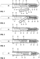
Figure 1 is a side sectional view illustrating the device and a cartridge; -
Figure 2 is a side sectional view illustrating placement of the cartridge in the device; -
Figure 3 is a side sectional view illustrating the cartridge in the device with piercing of the septum; -
Figure 4 is a side sectional view illustrating initial movement of the cartridge within the holder; -
Figure 5 is a side sectional view illustrating further movement of the cartridge and needle hub; -
Figure 6 is a side sectional view illustrating further movement of a plunger rod; -
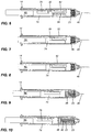
Figures 7 and 8 are side sectional views illustrating progression of the movement and injection of the cartridge contents; -
Figure 9 is a side sectional view illustrating rearward movement of the needle hub, cartridge and cartridge holder; -
Figure 10 is a side sectional view illustrating the device after injection and withdrawal of the needle; -
Figure 11 is a side sectional view of the housing; -
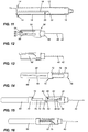
Figure 12 is a perspective view of the needle hub and cartridge holder; -
Figure 13 is a further perspective view of the needle hub and cartridge holder; -
Figure 14 is a perspective view of the plunger rod assembly; -
Figure 15 is a perspective view illustrating the initial engagement of the plunger rod and needle hub; and -
Figure 16 is a perspective view showing the position of the needle hub and plunger rod after injection. - Referring to the drawings and by reference characters thereto, there is illustrated in
Figures 1 to 10 the device of the present invention (generally designated by reference numeral 10) along with a cartridge generally designated byreference numeral 26. - Device 10 has an outer generally cylindrically shaped
housing 12. Aflange 14 is provided at the proximal end ofhousing 12 while at the distal end ofhousing 12 there is provided acap 16.Cap 16 is screwthreadedly engaged with the distal end ofhousing 12. It will be noted that there is an aperture oropening 17 incap 16 to provide for a needle passing therethrough. Aslot 15 formed in an areaadjacent flange 14 for reasons discussed hereinbelow. - As may be seen in
Figure 11 , there is alongitudinally extending rib 18 formed on the inner surface ofhousing 12. Whilerib 18 is shown extending a substantial length of thehousing 12, it is only the upper or distal portion which is required in many embodiments.Rib 18 is provided with a recess generally designated byreference numeral 20.Rib 18 also has an angledtop wall 22. Anopening 19 is provided inhousing 12 to permit the insertion of a cartridge as seen inFigures 1 to 10 . -
Cartridge 26 may be a standard cartridge or vial and will contain the medicament to be injected into the patient.Cartridge 26, as is conventional in the art, has aseptum 28 and acap 30 coveringseptum 28. Aplunger 32 is mounted interiorly of the cartridge at the proximal end thereof to prevent loss ofmedicament 34. - A
moveable needle hub 38 is mounted withinhousing 12 and there is provided aneedle 40.Needle 40 includes a distalend piercing tip 42 for injection into the patient and a proximal piercingtip 44 which is arranged to pierceseptum 28 ofcartridge 26 to provide access tomedicament 34. -
Needle hub 38 has an uppercylindrical portion 46 and a cartridge receiving member defined by a lowersemi-cylindrical wall 48 depending downwardly therefrom. On the exterior ofsemi-cylindrical wall 48, there is formed a recess 50 which extends partially intowall 48. A raisedland portion 52 is located within recess 50 to define afirst channel 54 and asecond channel 56. Arecess 61 is formed insecond channel 56 byprotrusion 63. At the lower end of raisedland portion 52, there is provided a firstangled bottom wall 58 which meets aside wall 60 so as to form a small notch. On the opposite side, there is provided a secondangled bottom wall 62. A further angledwall section 59 is provided onneedle hub 38 proximate an upper portion thereof. - A plunger rod assembly generally designated by
reference numeral 66 has a lowercylindrical portion 68 at the top of which there is formed aenlarged portion 70 having aslot 72 formed therein for reasons which will be discussed hereinbelow. Arib 65 is formed on the exterior of lowercylindrical portion 68 for engagement withslot 15. -
Plunger rod 66 also includes an upperpartial wall 74 which extends about a central pushingrod 76 which is sized to fit withinvial 26 to pushplunger 32. At an upper corner of upperpartial will 74, there is provided arecess 75 having a hook configuration. -
Vial 26 is inserted through opening 19 inhousing 12 as may be seen inFigures 1 and 2 . If desired, it can be arranged such thatvial 26 hasseptum 28 pierced by lower piercingend 44 upon insertion. Aspring 23 extends about the upper portion ofneedle 40. - Initially,
recess portion 75 engagesend wall 62 which is tapered. The hooked nature ofrecess 75 ensures that the two walls remain in contact for a period of time sufficient for piercingend 44 to pierceseptum 28. Continued pressure onplunger rod 66 will causecorners 75 and 71 to disengage and impart a rotational movement toneedle hub 38. In turn, this will allowrib 18 to enterfirst channel 54. Continued pressure onplunger rod 66 will causecorner 75 to contact slantedwall 59. This causes a further rotation ofneedle hub 38 with respect tohousing 12. This further rotation will cause the upper end ofrib 18 to enter intochannel 56. In so doing, pressure will be exerted until the top ofrib 18 entersrecess 61. The rib is then in a locked position andneedle hub 38 is pushed rearwardly byspring 23. The continued engagement of the top ofrib 18 withinrecess 61 assures that the needle cannot be exposed as it is locked in place.
Claims (6)
- An injection device comprising:a housing (12), an aperture (19) in a side wall of said housing;a needle hub (38), a needle (40) mounted in said needle hub (38), said needle (40) having a distal end piercing tip (42) and a proximal end piercing tip (44); said needle hub (38) being slidably mounted within said housing (12), said needle hub (38) being movable from a first position wherein said distal end piercing tip (42) is within said housing (12) to a second position wherein said distal end piercing tip (42) extends outwardly of said housing (12);a spring (23) biasing said needle hub (38) towards said first position;a cartridge receiving member (48) mounted within said housing, anda plunger rod assembly (66) for exerting pressure on said cartridge receiving member (48) to move said cartridge (26) and said needle hub (38) from said first position to said second position, said plunger rod assembly (66) and said cartridge receiving member (48) having cooperating means such that when said plunger rod assembly is pushed to cause the cartridge plunger to be pierced by said proximal end piercing tip, a rotational movement is imparted to said cartridge receiving member (48), characterized in thatthe cartridge receiving member (48) is accessible through said aperture (19) in said side wall of said housing;when said plunger rod assembly (66) is pushed to cause the cartridge plunger to be pierced by said proximal end piercing tip (44), a rotational movement is imparted to said cartridge receiving member (48) to thereby prevent access to said cartridge through said aperture in said side wall of said housing.
- The injection device of Claim 1 wherein said cartridge receiving member (48) and said needle hub (38) are integral.
- The injection device of Claim 2 wherein said plunger rod assembly (66) has a pusher rod (76) and an upper partial wall (74) partially surrounding said pusher wall, said upper partial wall (74) having a length greater than said pusher rod (76).
- The injection device of Claim 3 wherein said upper partial wall (74) has an angled corner (75), said cartridge receiving member (48) having a cartridge receiving member partial wall, said cartridge receiving member partial wall having a tapered corner (62) to engage with said angled corner (75) on said upper partial wall (74) to permit pushing of said cartridge receiving member (48) upwardly.
- The injection device of Claim 4 wherein contact of said upper partial wall (74) and said cartridge receiving member partial wall causes said cartridge receiving member (48) to rotate and thereby cause said cartridge receiving member partial wall to block said opening in said housing to thereby prevent removal of said cartridge therefrom.
- The injection device of Claim 5 wherein said housing has a protrusion on an inner surface thereof, said cartridge receiving member having first and second channels, said second channel having a recess formed therein to engage said protrusion on said inner surface of said housing to prevent further movement of said cartridge receiving member.
Applications Claiming Priority (2)
| Application Number | Priority Date | Filing Date | Title |
|---|---|---|---|
| CA2695265A CA2695265A1 (en) | 2010-03-02 | 2010-03-02 | Injection device |
| PCT/CA2011/000210 WO2011106870A1 (en) | 2010-03-02 | 2011-02-28 | Injection device |
Publications (3)
| Publication Number | Publication Date |
|---|---|
| EP2542282A1 EP2542282A1 (en) | 2013-01-09 |
| EP2542282A4 EP2542282A4 (en) | 2014-07-23 |
| EP2542282B1 true EP2542282B1 (en) | 2017-11-15 |
Family
ID=44515260
Family Applications (1)
| Application Number | Title | Priority Date | Filing Date |
|---|---|---|---|
| EP11750109.8A Active EP2542282B1 (en) | 2010-03-02 | 2011-02-28 | Injection device |
Country Status (8)
| Country | Link |
|---|---|
| US (1) | US9452267B2 (en) |
| EP (1) | EP2542282B1 (en) |
| JP (1) | JP5815568B2 (en) |
| CN (1) | CN102858394B (en) |
| AU (1) | AU2011223441B2 (en) |
| CA (2) | CA2695265A1 (en) |
| ES (1) | ES2650386T3 (en) |
| WO (1) | WO2011106870A1 (en) |
Families Citing this family (14)
| Publication number | Priority date | Publication date | Assignee | Title |
|---|---|---|---|---|
| DE102012024371A1 (en) | 2012-12-13 | 2014-06-18 | Schott Ag | Storage device Storage of liquid media, in particular medicines and methods for dispensing liquid media |
| SG10201509159TA (en) * | 2015-11-05 | 2017-06-29 | Arrow-Med Design Pte Ltd | Injection device |
| FR3044218B1 (en) * | 2015-11-30 | 2017-12-29 | Biocorp Prod | DEVICE FOR CONNECTION BETWEEN A CONTAINER AND A CONTAINER, CONNECTION ASSEMBLY COMPRISING SUCH A DEVICE |
| JP7155145B2 (en) | 2017-03-15 | 2022-10-18 | ノバルティス アーゲー | System for administering pharmaceuticals |
| EP3596636A1 (en) | 2017-03-15 | 2020-01-22 | Novartis AG | System for use of a pharmaceutical product |
| CN110546713B (en) | 2017-03-15 | 2023-10-27 | 诺瓦提斯公司 | Medical device, programming device, wireless terminal, and medical system |
| US20200069872A1 (en) * | 2017-03-16 | 2020-03-05 | Novartis Ag | Piercing mechanism and cartridge piercing system |
| WO2018167136A1 (en) * | 2017-03-16 | 2018-09-20 | Novartis Ag | Piercing mechanism and cartridge piercing system |
| EP3595739B1 (en) | 2017-03-16 | 2021-04-07 | Novartis AG | Injector device |
| CA2971263A1 (en) * | 2017-06-19 | 2018-12-19 | Duoject Medical Systems Inc. | Injector for drugs |
| CN111511419B (en) | 2017-12-21 | 2022-10-21 | 英杰特药业瑞典有限公司 | Automatic injector for reducing oxygen in package |
| CN109224203A (en) * | 2018-10-30 | 2019-01-18 | 天津思盛科技有限公司 | A kind of cone joint oral cavity card occupies bottle anesthetic driving means |
| JP7178282B2 (en) | 2019-02-01 | 2022-11-25 | 三協立山株式会社 | Fittings |
| CA3050501A1 (en) * | 2019-07-24 | 2021-01-24 | Duoject Medical Systems Inc. | Injection device |
Family Cites Families (30)
| Publication number | Priority date | Publication date | Assignee | Title |
|---|---|---|---|---|
| US1852658A (en) * | 1930-05-28 | 1932-04-05 | Clifford S Kile | Liquid ejecting device |
| US2994323A (en) * | 1958-12-11 | 1961-08-01 | American Home Prod | Cartridge-syringe assembly |
| US3848593A (en) * | 1970-10-09 | 1974-11-19 | Affiliated Hospital Prod | Side loading disposable carpule syringe |
| US4898590A (en) * | 1988-06-24 | 1990-02-06 | Research Foundation Of The State University Of N.Y. | Syringe having protective sleeve |
| US5263942A (en) * | 1991-04-08 | 1993-11-23 | Habley Medical Technology Corporation | Packaged pharmaceutical-type safety syringe with off-axis needle cannula |
| US5593391A (en) * | 1992-02-13 | 1997-01-14 | Stanners; Sydney D. | Ampule safety syringe |
| US5403288A (en) * | 1992-02-13 | 1995-04-04 | Stanners; Sydney D. | Safety sleeve for dental syringe |
| DE69302852T2 (en) * | 1992-03-27 | 1996-09-26 | Duphar Int Res | Automatic syringe |
| US5531683A (en) * | 1992-08-13 | 1996-07-02 | Science Incorporated | Mixing and delivery syringe assembly |
| US5451214A (en) * | 1993-03-22 | 1995-09-19 | Hajishoreh; Kaveh-Karimi | Syringe apparatus |
| SE9301494D0 (en) * | 1993-04-30 | 1993-04-30 | Kabi Pharmacia Ab | A DEVICE FOR DOSING LIQUID PREPARATION |
| US6090082A (en) * | 1998-02-23 | 2000-07-18 | Becton, Dickinson And Company | Vial retainer interface to a medication delivery pen |
| US6221055B1 (en) * | 1998-03-04 | 2001-04-24 | Retractable Technologies, Inc. | Retractable dental syringe |
| US6319233B1 (en) * | 1998-04-17 | 2001-11-20 | Becton, Dickinson And Company | Safety shield system for prefilled syringes |
| US6036675A (en) * | 1999-02-03 | 2000-03-14 | Specialized Health Products, Inc. | Safety sterile cartride unit apparatus and methods |
| US6428517B1 (en) | 1999-05-10 | 2002-08-06 | Milestone Scientific, Inc. | Hand-piece for injection device with a retractable and rotating needle |
| US20050171486A1 (en) | 1999-05-10 | 2005-08-04 | Hochman Mark N. | Safety syringe |
| WO2001060436A1 (en) * | 2000-02-15 | 2001-08-23 | Comar, Inc. | Needleless access apparatus and system |
| US6190361B1 (en) * | 2000-04-18 | 2001-02-20 | Gettig Technologies, Inc. | Selectively lockable needle guard |
| IL161682A0 (en) * | 2001-11-02 | 2004-09-27 | Meridian Medical Technologies | A medicament container, a medicament dispensing kit for administering medication and a method for packaging the same |
| US20030105430A1 (en) * | 2001-11-30 | 2003-06-05 | Elan Pharma International Limited Wil House | Automatic injector |
| WO2004020026A1 (en) * | 2002-08-29 | 2004-03-11 | Novo Nordisk A/S | Frontloaded injection device |
| NZ554828A (en) * | 2004-12-06 | 2010-07-30 | Washington Biotech Corp | Medicine injection devices and methods |
| CA2652592C (en) | 2006-05-16 | 2014-11-04 | Hospira, Inc. | Injection device and method of assembly and activation |
| CN101130120A (en) * | 2006-08-24 | 2008-02-27 | 郑万章 | Portion abandoning type tube needle bed of agent |
| US7384414B1 (en) * | 2007-01-23 | 2008-06-10 | Becton, Dickinson And Company | Safety pen needle with non-injection end passive safety features |
| CN101912648B (en) * | 2008-01-23 | 2013-04-24 | 诺沃-诺迪斯克有限公司 | Device for injecting apportioned doses of liquid drug |
| DE202008016246U1 (en) | 2008-12-08 | 2009-03-05 | Synovamed Ag | carpule syringe |
| DE102009048497A1 (en) * | 2009-09-26 | 2011-03-31 | Haselmeier Gmbh | injection device |
| US20130245604A1 (en) * | 2010-11-29 | 2013-09-19 | Sanofi-Aventis Deutschland Gmbh | Auto-Injector Device with a Medicated Module |
-
2010
- 2010-03-02 CA CA2695265A patent/CA2695265A1/en not_active Abandoned
-
2011
- 2011-02-28 ES ES11750109.8T patent/ES2650386T3/en active Active
- 2011-02-28 US US13/261,424 patent/US9452267B2/en active Active
- 2011-02-28 EP EP11750109.8A patent/EP2542282B1/en active Active
- 2011-02-28 CN CN201180020766.0A patent/CN102858394B/en active Active
- 2011-02-28 AU AU2011223441A patent/AU2011223441B2/en active Active
- 2011-02-28 JP JP2012555262A patent/JP5815568B2/en active Active
- 2011-02-28 CA CA2801889A patent/CA2801889C/en not_active Expired - Fee Related
- 2011-02-28 WO PCT/CA2011/000210 patent/WO2011106870A1/en active Application Filing
Non-Patent Citations (1)
| Title |
|---|
| None * |
Also Published As
| Publication number | Publication date |
|---|---|
| CN102858394B (en) | 2015-07-01 |
| EP2542282A1 (en) | 2013-01-09 |
| AU2011223441A1 (en) | 2012-10-18 |
| US20130018324A1 (en) | 2013-01-17 |
| WO2011106870A1 (en) | 2011-09-09 |
| AU2011223441B2 (en) | 2015-03-12 |
| JP5815568B2 (en) | 2015-11-17 |
| CA2801889A1 (en) | 2011-09-09 |
| EP2542282A4 (en) | 2014-07-23 |
| ES2650386T3 (en) | 2018-01-18 |
| CA2801889C (en) | 2017-10-17 |
| US9452267B2 (en) | 2016-09-27 |
| CA2695265A1 (en) | 2011-09-02 |
| JP2013521020A (en) | 2013-06-10 |
| CN102858394A (en) | 2013-01-02 |
Similar Documents
| Publication | Publication Date | Title |
|---|---|---|
| EP2542282B1 (en) | Injection device | |
| US9662457B2 (en) | Injection device | |
| EP1753492B1 (en) | Passive delivery system diluents mixing and delivery | |
| US9700682B2 (en) | Device for retaining and storing liquid media and method of expelling the liquid media | |
| US8500699B2 (en) | Pre-filled syringe apparatus having internal guard | |
| US6746420B1 (en) | Parenteral apparatus | |
| US20130018326A1 (en) | Medical fluid injection device and system | |
| US20230310756A1 (en) | Injection device | |
| EP1961437B1 (en) | Instrument for injections with retractable needle following use | |
| CN109310822A (en) | Injection device | |
| AU2012267161A1 (en) | Injection device | |
| AU755381B2 (en) | A parenteral apparatus | |
| EP2559449A1 (en) | Safety syringe |
Legal Events
| Date | Code | Title | Description |
|---|---|---|---|
| PUAI | Public reference made under article 153(3) epc to a published international application that has entered the european phase |
Free format text: ORIGINAL CODE: 0009012 |
|
| 17P | Request for examination filed |
Effective date: 20120912 |
|
| AK | Designated contracting states |
Kind code of ref document: A1 Designated state(s): AL AT BE BG CH CY CZ DE DK EE ES FI FR GB GR HR HU IE IS IT LI LT LU LV MC MK MT NL NO PL PT RO RS SE SI SK SM TR |
|
| DAX | Request for extension of the european patent (deleted) | ||
| A4 | Supplementary search report drawn up and despatched |
Effective date: 20140624 |
|
| RIC1 | Information provided on ipc code assigned before grant |
Ipc: A61M 5/24 20060101ALI20140617BHEP Ipc: A61M 5/31 20060101ALI20140617BHEP Ipc: A61M 5/32 20060101AFI20140617BHEP |
|
| GRAP | Despatch of communication of intention to grant a patent |
Free format text: ORIGINAL CODE: EPIDOSNIGR1 |
|
| STAA | Information on the status of an ep patent application or granted ep patent |
Free format text: STATUS: GRANT OF PATENT IS INTENDED |
|
| RIN1 | Information on inventor provided before grant (corrected) |
Inventor name: REYNOLDS, DAVID, L. Inventor name: MACDONALD, DANIEL Inventor name: TREPANIER, JULIE Inventor name: TREMBLAY, YAN |
|
| INTG | Intention to grant announced |
Effective date: 20170419 |
|
| RAP1 | Party data changed (applicant data changed or rights of an application transferred) |
Owner name: DUOJECT MEDICAL SYSTEMS INC. |
|
| GRAS | Grant fee paid |
Free format text: ORIGINAL CODE: EPIDOSNIGR3 |
|
| GRAA | (expected) grant |
Free format text: ORIGINAL CODE: 0009210 |
|
| STAA | Information on the status of an ep patent application or granted ep patent |
Free format text: STATUS: THE PATENT HAS BEEN GRANTED |
|
| APBM | Appeal reference recorded |
Free format text: ORIGINAL CODE: EPIDOSNREFNO |
|
| PUAC | Information related to the publication of a b1 document modified or deleted |
Free format text: ORIGINAL CODE: 0009299EPPU |
|
| STAA | Information on the status of an ep patent application or granted ep patent |
Free format text: STATUS: GRANT OF PATENT IS INTENDED |
|
| APBV | Interlocutory revision of appeal recorded |
Free format text: ORIGINAL CODE: EPIDOSNIRAPE |
|
| GRAJ | Information related to disapproval of communication of intention to grant by the applicant or resumption of examination proceedings by the epo deleted |
Free format text: ORIGINAL CODE: EPIDOSDIGR1 |
|
| GRAL | Information related to payment of fee for publishing/printing deleted |
Free format text: ORIGINAL CODE: EPIDOSDIGR3 |
|
| STAA | Information on the status of an ep patent application or granted ep patent |
Free format text: STATUS: REQUEST FOR EXAMINATION WAS MADE |
|
| AK | Designated contracting states |
Kind code of ref document: B1 Designated state(s): AL AT BE BG CH CY CZ DE DK EE ES FI FR GB GR HR HU IE IS IT LI LT LU LV MC MK MT NL NO PL PT RO RS SE SI SK SM TR |
|
| REG | Reference to a national code |
Ref country code: GB Ref legal event code: FG4D |
|
| REG | Reference to a national code |
Ref country code: CH Ref legal event code: EP Ref country code: CH Ref legal event code: PK Free format text: DIE ERTEILUNG WURDE VOM EPA WIDERRUFEN. |
|
| DB1 | Publication of patent cancelled |
Effective date: 20170811 |
|
| REG | Reference to a national code |
Ref country code: AT Ref legal event code: REF Ref document number: 920661 Country of ref document: AT Kind code of ref document: T Effective date: 20170915 |
|
| INTC | Intention to grant announced (deleted) | ||
| REG | Reference to a national code |
Ref country code: IE Ref legal event code: FG4D |
|
| REG | Reference to a national code |
Ref country code: DE Ref legal event code: R096 Ref document number: 602011040882 Country of ref document: DE |
|
| GRAR | Information related to intention to grant a patent recorded |
Free format text: ORIGINAL CODE: EPIDOSNIGR71 |
|
| REG | Reference to a national code |
Ref country code: LU Ref legal event code: HK Effective date: 20170906 |
|
| STAA | Information on the status of an ep patent application or granted ep patent |
Free format text: STATUS: GRANT OF PATENT IS INTENDED |
|
| GRAA | (expected) grant |
Free format text: ORIGINAL CODE: 0009210 |
|
| STAA | Information on the status of an ep patent application or granted ep patent |
Free format text: STATUS: THE PATENT HAS BEEN GRANTED |
|
| REG | Reference to a national code |
Ref country code: AT Ref legal event code: REZ Ref document number: 920661 Country of ref document: AT Kind code of ref document: T Effective date: 20170823 |
|
| REG | Reference to a national code |
Ref country code: DE Ref legal event code: R107 Ref document number: 602011040882 Country of ref document: DE |
|
| AK | Designated contracting states |
Kind code of ref document: B1 Designated state(s): AL AT BE BG CH CY CZ DE DK EE ES FI FR GB GR HR HU IE IS IT LI LT LU LV MC MK MT NL NO PL PT RO RS SE SI SK SM TR |
|
| INTG | Intention to grant announced |
Effective date: 20171010 |
|
| REG | Reference to a national code |
Ref country code: CH Ref legal event code: EP Ref country code: CH Ref legal event code: PK Free format text: DIE ERTEILUNG VOM 23.08.2017 WURDE VOM EPA WIDERRUFEN |
|
| REG | Reference to a national code |
Ref country code: DE Ref legal event code: R096 Ref document number: 602011040882 Country of ref document: DE |
|
| REG | Reference to a national code |
Ref country code: ES Ref legal event code: FG2A Ref document number: 2650386 Country of ref document: ES Kind code of ref document: T3 Effective date: 20180118 |
|
| PG25 | Lapsed in a contracting state [announced via postgrant information from national office to epo] |
Ref country code: NO Free format text: LAPSE BECAUSE OF FAILURE TO SUBMIT A TRANSLATION OF THE DESCRIPTION OR TO PAY THE FEE WITHIN THE PRESCRIBED TIME-LIMIT Effective date: 20171123 |
|
| REG | Reference to a national code |
Ref country code: FR Ref legal event code: PLFP Year of fee payment: 8 |
|
| PG25 | Lapsed in a contracting state [announced via postgrant information from national office to epo] |
Ref country code: GR Free format text: LAPSE BECAUSE OF FAILURE TO SUBMIT A TRANSLATION OF THE DESCRIPTION OR TO PAY THE FEE WITHIN THE PRESCRIBED TIME-LIMIT Effective date: 20171124 Ref country code: IS Free format text: LAPSE BECAUSE OF FAILURE TO SUBMIT A TRANSLATION OF THE DESCRIPTION OR TO PAY THE FEE WITHIN THE PRESCRIBED TIME-LIMIT Effective date: 20171223 |
|
| REG | Reference to a national code |
Ref country code: NL Ref legal event code: MP Effective date: 20171115 |
|
| REG | Reference to a national code |
Ref country code: LT Ref legal event code: MG4D |
|
| PG25 | Lapsed in a contracting state [announced via postgrant information from national office to epo] |
Ref country code: NL Free format text: LAPSE BECAUSE OF FAILURE TO SUBMIT A TRANSLATION OF THE DESCRIPTION OR TO PAY THE FEE WITHIN THE PRESCRIBED TIME-LIMIT Effective date: 20171115 Ref country code: FI Free format text: LAPSE BECAUSE OF FAILURE TO SUBMIT A TRANSLATION OF THE DESCRIPTION OR TO PAY THE FEE WITHIN THE PRESCRIBED TIME-LIMIT Effective date: 20171115 Ref country code: NO Free format text: LAPSE BECAUSE OF FAILURE TO SUBMIT A TRANSLATION OF THE DESCRIPTION OR TO PAY THE FEE WITHIN THE PRESCRIBED TIME-LIMIT Effective date: 20180215 Ref country code: LT Free format text: LAPSE BECAUSE OF FAILURE TO SUBMIT A TRANSLATION OF THE DESCRIPTION OR TO PAY THE FEE WITHIN THE PRESCRIBED TIME-LIMIT Effective date: 20171115 |
|
| PG25 | Lapsed in a contracting state [announced via postgrant information from national office to epo] |
Ref country code: HR Free format text: LAPSE BECAUSE OF FAILURE TO SUBMIT A TRANSLATION OF THE DESCRIPTION OR TO PAY THE FEE WITHIN THE PRESCRIBED TIME-LIMIT Effective date: 20171115 Ref country code: BG Free format text: LAPSE BECAUSE OF FAILURE TO SUBMIT A TRANSLATION OF THE DESCRIPTION OR TO PAY THE FEE WITHIN THE PRESCRIBED TIME-LIMIT Effective date: 20180215 Ref country code: RS Free format text: LAPSE BECAUSE OF FAILURE TO SUBMIT A TRANSLATION OF THE DESCRIPTION OR TO PAY THE FEE WITHIN THE PRESCRIBED TIME-LIMIT Effective date: 20171115 |
|
| PG25 | Lapsed in a contracting state [announced via postgrant information from national office to epo] |
Ref country code: SK Free format text: LAPSE BECAUSE OF FAILURE TO SUBMIT A TRANSLATION OF THE DESCRIPTION OR TO PAY THE FEE WITHIN THE PRESCRIBED TIME-LIMIT Effective date: 20171115 Ref country code: CZ Free format text: LAPSE BECAUSE OF FAILURE TO SUBMIT A TRANSLATION OF THE DESCRIPTION OR TO PAY THE FEE WITHIN THE PRESCRIBED TIME-LIMIT Effective date: 20171115 Ref country code: DK Free format text: LAPSE BECAUSE OF FAILURE TO SUBMIT A TRANSLATION OF THE DESCRIPTION OR TO PAY THE FEE WITHIN THE PRESCRIBED TIME-LIMIT Effective date: 20171115 Ref country code: EE Free format text: LAPSE BECAUSE OF FAILURE TO SUBMIT A TRANSLATION OF THE DESCRIPTION OR TO PAY THE FEE WITHIN THE PRESCRIBED TIME-LIMIT Effective date: 20171115 Ref country code: CY Free format text: LAPSE BECAUSE OF FAILURE TO SUBMIT A TRANSLATION OF THE DESCRIPTION OR TO PAY THE FEE WITHIN THE PRESCRIBED TIME-LIMIT Effective date: 20171115 |
|
| REG | Reference to a national code |
Ref country code: DE Ref legal event code: R097 Ref document number: 602011040882 Country of ref document: DE |
|
| PG25 | Lapsed in a contracting state [announced via postgrant information from national office to epo] |
Ref country code: SM Free format text: LAPSE BECAUSE OF FAILURE TO SUBMIT A TRANSLATION OF THE DESCRIPTION OR TO PAY THE FEE WITHIN THE PRESCRIBED TIME-LIMIT Effective date: 20171115 Ref country code: RO Free format text: LAPSE BECAUSE OF FAILURE TO SUBMIT A TRANSLATION OF THE DESCRIPTION OR TO PAY THE FEE WITHIN THE PRESCRIBED TIME-LIMIT Effective date: 20171115 |
|
| REG | Reference to a national code |
Ref country code: CH Ref legal event code: PL |
|
| PLBE | No opposition filed within time limit |
Free format text: ORIGINAL CODE: 0009261 |
|
| STAA | Information on the status of an ep patent application or granted ep patent |
Free format text: STATUS: NO OPPOSITION FILED WITHIN TIME LIMIT |
|
| PG25 | Lapsed in a contracting state [announced via postgrant information from national office to epo] |
Ref country code: MC Free format text: LAPSE BECAUSE OF FAILURE TO SUBMIT A TRANSLATION OF THE DESCRIPTION OR TO PAY THE FEE WITHIN THE PRESCRIBED TIME-LIMIT Effective date: 20171115 |
|
| 26N | No opposition filed |
Effective date: 20180817 |
|
| REG | Reference to a national code |
Ref country code: IE Ref legal event code: MM4A |
|
| REG | Reference to a national code |
Ref country code: BE Ref legal event code: MM Effective date: 20180228 |
|
| PG25 | Lapsed in a contracting state [announced via postgrant information from national office to epo] |
Ref country code: SI Free format text: LAPSE BECAUSE OF FAILURE TO SUBMIT A TRANSLATION OF THE DESCRIPTION OR TO PAY THE FEE WITHIN THE PRESCRIBED TIME-LIMIT Effective date: 20171115 Ref country code: LI Free format text: LAPSE BECAUSE OF NON-PAYMENT OF DUE FEES Effective date: 20180228 Ref country code: CH Free format text: LAPSE BECAUSE OF NON-PAYMENT OF DUE FEES Effective date: 20180228 Ref country code: LU Free format text: LAPSE BECAUSE OF NON-PAYMENT OF DUE FEES Effective date: 20180228 |
|
| PG25 | Lapsed in a contracting state [announced via postgrant information from national office to epo] |
Ref country code: IE Free format text: LAPSE BECAUSE OF NON-PAYMENT OF DUE FEES Effective date: 20180228 |
|
| PG25 | Lapsed in a contracting state [announced via postgrant information from national office to epo] |
Ref country code: BE Free format text: LAPSE BECAUSE OF NON-PAYMENT OF DUE FEES Effective date: 20180228 |
|
| PG25 | Lapsed in a contracting state [announced via postgrant information from national office to epo] |
Ref country code: MT Free format text: LAPSE BECAUSE OF NON-PAYMENT OF DUE FEES Effective date: 20180228 |
|
| PG25 | Lapsed in a contracting state [announced via postgrant information from national office to epo] |
Ref country code: TR Free format text: LAPSE BECAUSE OF FAILURE TO SUBMIT A TRANSLATION OF THE DESCRIPTION OR TO PAY THE FEE WITHIN THE PRESCRIBED TIME-LIMIT Effective date: 20171115 |
|
| PG25 | Lapsed in a contracting state [announced via postgrant information from national office to epo] |
Ref country code: HU Free format text: LAPSE BECAUSE OF FAILURE TO SUBMIT A TRANSLATION OF THE DESCRIPTION OR TO PAY THE FEE WITHIN THE PRESCRIBED TIME-LIMIT; INVALID AB INITIO Effective date: 20110228 Ref country code: PT Free format text: LAPSE BECAUSE OF FAILURE TO SUBMIT A TRANSLATION OF THE DESCRIPTION OR TO PAY THE FEE WITHIN THE PRESCRIBED TIME-LIMIT Effective date: 20171115 |
|
| PG25 | Lapsed in a contracting state [announced via postgrant information from national office to epo] |
Ref country code: LV Free format text: LAPSE BECAUSE OF NON-PAYMENT OF DUE FEES Effective date: 20171115 Ref country code: MK Free format text: LAPSE BECAUSE OF NON-PAYMENT OF DUE FEES Effective date: 20171115 Ref country code: SE Free format text: LAPSE BECAUSE OF FAILURE TO SUBMIT A TRANSLATION OF THE DESCRIPTION OR TO PAY THE FEE WITHIN THE PRESCRIBED TIME-LIMIT Effective date: 20171115 |
|
| PG25 | Lapsed in a contracting state [announced via postgrant information from national office to epo] |
Ref country code: AL Free format text: LAPSE BECAUSE OF FAILURE TO SUBMIT A TRANSLATION OF THE DESCRIPTION OR TO PAY THE FEE WITHIN THE PRESCRIBED TIME-LIMIT Effective date: 20171115 |
|
| PG25 | Lapsed in a contracting state [announced via postgrant information from national office to epo] |
Ref country code: PL Free format text: LAPSE BECAUSE OF NON-PAYMENT OF DUE FEES Effective date: 20171115 |
|
| PG25 | Lapsed in a contracting state [announced via postgrant information from national office to epo] |
Ref country code: AT Free format text: LAPSE BECAUSE OF NON-PAYMENT OF DUE FEES Effective date: 20171115 |
|
| REG | Reference to a national code |
Ref country code: DE Ref legal event code: R081 Ref document number: 602011040882 Country of ref document: DE Owner name: SIMON WILLIAMS PHARMA CONSULTING LLC, GIBBSBOR, US Free format text: FORMER OWNER: DUOJECT MEDICAL SYSTEMS INC., BROMONT, QUEBEC, CA |
|
| REG | Reference to a national code |
Ref country code: GB Ref legal event code: 732E Free format text: REGISTERED BETWEEN 20230525 AND 20230601 |
|
| PGFP | Annual fee paid to national office [announced via postgrant information from national office to epo] |
Ref country code: FR Payment date: 20230621 Year of fee payment: 13 Ref country code: ES Payment date: 20230627 Year of fee payment: 13 Ref country code: DE Payment date: 20230530 Year of fee payment: 13 |
|
| PGFP | Annual fee paid to national office [announced via postgrant information from national office to epo] |
Ref country code: IT Payment date: 20230623 Year of fee payment: 13 Ref country code: GB Payment date: 20230620 Year of fee payment: 13 |
|
| PGFP | Annual fee paid to national office [announced via postgrant information from national office to epo] |
Ref country code: ES Payment date: 20240325 Year of fee payment: 14 |