EP3147003A1 - Cage de foot portable - Google Patents
Cage de foot portable Download PDFInfo
- Publication number
- EP3147003A1 EP3147003A1 EP16189389.6A EP16189389A EP3147003A1 EP 3147003 A1 EP3147003 A1 EP 3147003A1 EP 16189389 A EP16189389 A EP 16189389A EP 3147003 A1 EP3147003 A1 EP 3147003A1
- Authority
- EP
- European Patent Office
- Prior art keywords
- horizontal bar
- knob
- proximal end
- net
- distal end
- Prior art date
- Legal status (The legal status is an assumption and is not a legal conclusion. Google has not performed a legal analysis and makes no representation as to the accuracy of the status listed.)
- Withdrawn
Links
Images


Classifications
-
- A—HUMAN NECESSITIES
- A63—SPORTS; GAMES; AMUSEMENTS
- A63B—APPARATUS FOR PHYSICAL TRAINING, GYMNASTICS, SWIMMING, CLIMBING, OR FENCING; BALL GAMES; TRAINING EQUIPMENT
- A63B63/00—Targets or goals for ball games
- A63B63/004—Goals of the type used for football, handball, hockey or the like
-
- A—HUMAN NECESSITIES
- A63—SPORTS; GAMES; AMUSEMENTS
- A63B—APPARATUS FOR PHYSICAL TRAINING, GYMNASTICS, SWIMMING, CLIMBING, OR FENCING; BALL GAMES; TRAINING EQUIPMENT
- A63B63/00—Targets or goals for ball games
- A63B2063/002—Targets or goals for ball games variable in size
-
- A—HUMAN NECESSITIES
- A63—SPORTS; GAMES; AMUSEMENTS
- A63B—APPARATUS FOR PHYSICAL TRAINING, GYMNASTICS, SWIMMING, CLIMBING, OR FENCING; BALL GAMES; TRAINING EQUIPMENT
- A63B2209/00—Characteristics of used materials
- A63B2209/02—Characteristics of used materials with reinforcing fibres, e.g. carbon, polyamide fibres
-
- A—HUMAN NECESSITIES
- A63—SPORTS; GAMES; AMUSEMENTS
- A63B—APPARATUS FOR PHYSICAL TRAINING, GYMNASTICS, SWIMMING, CLIMBING, OR FENCING; BALL GAMES; TRAINING EQUIPMENT
- A63B2209/00—Characteristics of used materials
- A63B2209/10—Characteristics of used materials with adhesive type surfaces, i.e. hook and loop-type fastener
-
- A—HUMAN NECESSITIES
- A63—SPORTS; GAMES; AMUSEMENTS
- A63B—APPARATUS FOR PHYSICAL TRAINING, GYMNASTICS, SWIMMING, CLIMBING, OR FENCING; BALL GAMES; TRAINING EQUIPMENT
- A63B2210/00—Space saving
- A63B2210/50—Size reducing arrangements for stowing or transport
-
- A—HUMAN NECESSITIES
- A63—SPORTS; GAMES; AMUSEMENTS
- A63B—APPARATUS FOR PHYSICAL TRAINING, GYMNASTICS, SWIMMING, CLIMBING, OR FENCING; BALL GAMES; TRAINING EQUIPMENT
- A63B2243/00—Specific ball sports not provided for in A63B2102/00 - A63B2102/38
- A63B2243/0025—Football
Definitions
- the field of the present invention relates to a portable soccer goal frame for a soccer goal net with top side bar supports for a more realistic shape and less sag along the top mouth of the goal.
- the first problem is the sagging of the top cross bar which is made of fabric suspended between vertical posts over the top center of the goal.
- the second problem is the difficulty of set up.
- the third problem is that the portable goals do not replicate a real soccer goal as they do not form a proper "pocket" with a depth from the goal opening without adding extra vertical posts, which increase set up time and materials used to manufacture the goal.
- the fourth problem is lack of stability of prior portable goal nets, which tend to have more weight to the rear of the goal frame structure and thus are susceptible to movement and overturning when balls are kicked with greater force into the goal. Accordingly, improvements to portable soccer goals continue to be sought.
- a portable sports goal has a base having a center section, a left side section disposed at an angle to the center section, and a right side section disposed at an angle to the center section.
- a first socket extends upwardly from the left side section, and a second socket extends upwardly from the right side section.
- a first flexible pole that has a distal end and a proximal end is adapted to be removably inserted at its distal end into the first socket.
- a second flexible pole that has a distal end and a proximal end is adapted to be removably inserted at its distal end into the second socket.
- a first horizontal bar or top side bar is adapted for removable attachment to the proximal end of the first flexible pole.
- the first horizontal bar has a distal end and a proximal end and defines a length, and has a top surface and a bottom surface.
- a first knob projects upwardly from the top surface of the first horizontal bar.
- a first knob projects outwardly, preferably from a front surface, of the first horizontal bar.
- a second horizontal bar or top side bar is adapted for removable attachment to the proximal end of the second flexible pole.
- the second horizontal bar has a distal end and a proximal end and defines a length between its distal end and proximal end, and has a top surface and a bottom surface.
- a second knob projects upwardly from the top surface of the second horizontal bar.
- a first knob projects outwardly, preferably from a front surface, of the first horizontal bar.
- a net is removably attached to the frame formed by the base, poles and horizontal bars.
- the net has a top front edge and side front edges.
- the net is engagable to the first horizontal bar and the second horizontal bar so as to be held in tension along its top front edge and draped from the first horizontal bar and the second horizontal bar to the base.
- the net has a reinforcement tape along at least its top front edge, and preferably also along its two side front edges.
- the reinforcement tape at the top front edge defines a pocket adapted to receive either the first knob and the second knob of the horizontal bars, or a cord or wire that extends between the first knob and the second knob of the horizontal bars.
- the term "goal” is broadly construed to include any frame or other structure to which is attached or from which is suspended a net or fabric to create a target space or pocket into which a ball or puck is directed.
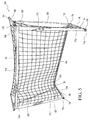
- FIGs. 1- 4 show a portable soccer goal 100 having a net 70 connected to a frame structure to support the net.
- the frame has a base 12 with a center bar or channel 14 and a left side bar or channel 16 and a right side bar or channel 18.
- the left side bar 16 is disposed at an angle from the center bar or channel 14 in the range of about 90 to 120 degrees.
- the right side bar 18 is disposed at an angle from the center bar or channel 14 in the range of about 90 to 120 degrees.
- the left side bar 16 and right side bar 18 are slidably removably joined to the center bar 14 such as with spring button release fasteners 20.
- the center bar 14 is separable into two or more pieces that are slidably removably joined together.
- the center bar 14 and left side bar 16 and right side bar 18 are of one integral piece.
- the base 12 can also be made using a folding metal base with locking buttons.
- the base 12 may be formed of an extruded metal tube or channel that is powder coated for improved weather resistance.
- a first socket 22 is welded to the top surface of the left side bar 16.
- a second socket 24 is welded to the top surface of the right side bar 18.
- the first socket 22 and second socket 24 define circular openings or hollows to receive distal ends of vertical poles 26, 28.
- the sockets 22, 24 may be adhesively joined, or the sockets 22, 24 may be integrally formed into the left side bar 16 and right side bar 18.
- the first socket 22 and second socket 24 are disposed at an angle from vertical and directed with their openings away from the center bar 14. In the embodiment shown in FIGs. 1 and 2 , the first socket 22 and second socket 24 are disposed at an angle in the range of 60 to 85 degrees from horizontal (e.g. from 0), or 5 to 30 degrees from vertical. The angle may be adjusted depending upon the size of the soccer goal (height and pocket).
- a first pole 26 has a distal end (or bottom end) and a proximal end (or top end) and is removably joined to the base 12 by inserting its distal end into the socket 22.
- a second pole 28 has a distal end (or bottom end) and a proximal end (or top end) and is removably joined to the base 12 by inserting its distal end into the socket 24.
- the first pole 26 and second pole 28 are flexible, and preferably are formed of fiberglass.
- Handgrips 30 may be installed around the circumference of each of the first pole 26 and second pole 28 for ease in handling when assembling the frame. Handgrips 30 may be formed of polyurethane foam or of molded rubber or like resilient materials.
- first pole 26 and second pole 28 have generally circular cross-sections. Alternatives to this include poles with oval or semi-oval cross-sections.
- the first horizontal bar 40 has a proximal end (or front end) and a distal end (or rear end), and has a top surface 56 and a bottom surface 57.
- the first horizontal bar 40 has reinforcing material or a step 50 extending downwardly from its bottom surface at or near the proximal end of the first horizontal bar 40.
- the step 50 defines a receiving hole or recess adapted to receive the proximal end (or top end) of the first pole 26.
- the receiving hole or recess is not centrally located along the length of the first horizontal bar 40, but is eccentrically located closer to the proximal end than to the distal end of the first horizontal bar 40.
- the first horizontal bar 40 has an upraised knob 58 extending up from the top surface 56 at or near the proximal end of the first horizontal bar.
- the knob 58 has a convexly curved upper knob surface.
- the first horizontal bar 40 additionally defines a net attachment point 64 at or near its distal end.
- the first horizontal bar 40 optionally is wider 54 at its proximal or front end that at its distal or rear end.
- a second horizontal bar 40b has a structure comparable to the first horizontal bar 40.
- the second horizontal bar 40b is adapted to receive the proximal end (or top end) of the second pole 28.
- a wire or cord 66 connects the first horizontal bar 40 to the second horizontal bar 40b.
- the wire or cord 66 extends from the distal end of the first horizontal bar 40 to the distal end of the second horizontal bar 40b.
- the wire or cord has a length equal to or shorter than the length of the center bar 14.
- the length of the wire or cord preferably is proportionate to the size of the soccer goal. For a six-foot (1.8 m) wide soccer goal, the length of the wire or cord would be approximately 6 feet (1.8 m), plus some added length for the attachment loops on the ends. For a twenty-four-foot (7.3 m) wide soccer goal, the length of the wire or cord would be approximately 24 feet (7.3 m) plus some added length for the attachment loops on the ends.
- the net 70 comprises a woven material having vertical strands 86 crossing horizontal strands 88.
- the net 70 further includes a reinforcement tape 74 at the front top horizontal center edge and reinforcement tapes 72 at the front side vertical edges.
- the reinforcement tapes 72, 74 together define the mouth of the goal.
- Loops 78 at the bottom edges of the front side reinforcement tapes 72 are secured around the front ends of the right side 16 and left side 18 of the base 12 (see FIGs. 1 and 4 ).
- the front ends of the right side 16 and left side 18 of the base 12 may have extensions or other fastening means to receive the loops 78.
- a pocket 80 is formed by or in the reinforcement tape 74 at the front top horizontal center edge.
- the knobs 58 extending from the top surfaces of the horizontal bars 40, 40b fit within the pocket 80 to hold the top portion of the net above a ground or floor surface.
- the flexible poles 26, 28 at their distal ends form pivot points. The flexible poles 26, 28 urge the horizontal bars 40, 40b apart to impart tension into the top horizontal center edge of the net 70, thus reducing sag at the top edge of the goal opening.
- Hook and loop fasteners e.g., Velcro
- Hook and loop fasteners are looped through bottom edges of the net 70 and around the base 12 to join the bottom of the net to the base.
- a portable soccer goal 100 of another embodiment of the invention has a net 170 connected to a frame structure to support the net.
- the frame has a base 112 with a center bar or channel 114 and a left side bar or channel 116 and a right side bar or channel 118.
- the left side bar 116 is disposed at an angle from the center bar or channel 114 in the range of about 90 to 120 degrees.
- the right side bar 118 is disposed at an angle from the center bar or channel 114 in the range of about 90 to 120 degrees.
- the left side bar 116 and right side bar 118 are slidably removably joined to the center bar 114 such as with spring button release fasteners 120.
- the center bar 114 is separable into two or more pieces that are slidably removably joined together.
- the center bar 114 and left side bar 116 and right side bar 118 are of one integral piece.
- the base 112 may be formed of an extruded metal tube or channel that is powder coated for improved weather resistance.
- a buckle footing 134 extends outwardly from the proximal ends of each of the left side bar 116 and right side bar 118 of the frame.
- the buckle footings 134 define openings through which stakes (not shown) may be inserted for joining the frame to a ground surface.
- a first socket 122 is welded to the top surface of the left side bar 116.
- a second socket 124 is welded to the top surface of the right side bar 118.
- the first socket 122 and second socket 124 define openings or hollows to receive distal ends of vertical poles 126, 128.
- the sockets 122, 124 may be adhesively joined, or the sockets 122, 124 may be integrally formed into the left side bar 116 and right side bar 118.
- the first socket 122 and second socket 124 are disposed at an angle from vertical and directed with their openings away from the center bar 114. In the embodiment shown in FIG. 5 , the first socket 122 and second socket 124 are disposed at an angle in the range of about 5 to 30 degrees from vertical.
- a first pole 126 has a distal end (or bottom end) and a proximal end (or top end) and is removably joined to the base 112 by inserting its distal end into the socket 122.
- a second pole 128 has a distal end (or bottom end) and a proximal end (or top end) and is removably joined to the base 112 by inserting its distal end into the socket 124.
- the first pole 126 and second pole 128 are flexible, and preferably are formed of fiberglass.
- Handgrips 130 may be installed around the circumference of each of the first pole 126 and second pole 28 for ease in handling when assembling the frame. Handgrips 130 may be formed of polyurethane foam or of molded rubber or like resilient materials. For a larger soccer goal, more fiberglass poles may be required to support the net. For example, for a goal that is eight-feet (2.4 m) tall, three poles generally will be required.
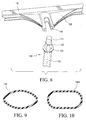
- first pole 126 and second pole 128 have generally oval 126A or semi-oval 126 cross-sections (see FIGs. 9 and 10 ). Alternatives to this include poles with round or other geometric cross-sections.
- the first pole and second pole 126, 128 are generally hollow poles causing the poles to flex or bend along their length.
- the first horizontal bar 140 has a proximal end (or front end) 142 and a distal end (or rear end) 144, and has a top surface 156 and a bottom surface 157.
- the first horizontal bar 140 has a downwardly depending neck 148 reinforced by shoulder flanges 150.
- the neck 148 defines a slot or hole 146 adapted to receive a top end portion 131 of either the first pole 126 or the second pole 128. See FIG. 8 .
- the slot or hole 146 is located centrally or approximately centrally between the proximal end and distal end of the first horizontal bar 140.
- the slot or hole 146 of the horizontal bar 140 receives the top end portion 131 of the pole 126, as well as the raised sleeve 132 and raised key section 133 of the pole 126 to secure the horizontal bar 140 against rotation on the pole 126.
- the first horizontal bar 140 has an upraised knob 164 extending up from the top surface 156 at or near the distal end of the first horizontal bar 126.
- the knob 164 has a convexly curved upper knob surface.
- the first horizontal bar 140 further has an outwardly projecting knob 160 extending from its proximal end 142. See FIG. 6 .
- a second horizontal bar 140 has a structure comparable to the first horizontal bar 140.
- the second horizontal bar 140 is adapted to receive the proximal end (or top end) of the second pole 128.
- a wire or cord 168 connects the proximal end of the first horizontal bar 140 to the proximal end of the second horizontal bar 140.
- the wire or cord 168 is looped 166 around the knob 160 projecting from the first horizontal bar, and is looped around the knob 160 extending from the second horizontal bar.
- the wire or cord has a length equal to or shorter than the length of the center bar 114.
- the length of the wire or cord 168 generally matches the length of the mouth of the soccer goal.
- a six-foot (1.8 m) wide goal will have a wire or cord with a length of 6 feet (1.8 m), plus some added length for the loops at the ends.
- the wire or cord 168 optionally may be elastic and have a stretch tension along its length.
- the net 170 includes a reinforcement tape 174 at the front top horizontal center edge and reinforcement tapes 172 at the front side vertical edges.
- the reinforcement tapes 172, 174 together define the mouth of the goal.
- Loops 176, 178 at the bottom edges of the front side reinforcement tapes 172 are secured around the front ends of the right side 116 and left side 118 of the base 112 (see FIG. 7 ).
- the loops 176,178 are extended around the bottom edges at locations spaced apart from the buckle footings 134, and the buckle footings serve a secondary function to maintain the loops 176, 178 on the base 112.
- the front ends of the right side 116 and left side 118 of the base 112 may have extensions or other fastening means to receive the loops 176, 178.
- Loops 180 182 extending from horizontal strands located at what will be the back corners of the net 170 are connected around the knobs 164 on the horizontal bars 140 to hold the top portion of the net 170 above a ground or floor surface by the poles 126, 128.
- a pocket 175 is formed by or in the reinforcement tape 174 at the front top horizontal center edge.
- the wire or cord 168 is threaded through the pocket 175 to hold the top portion of the net 170 above a ground or floor surface.
- the combination of horizontal bars 140 and poles 126, 128 create the goal opening or pocket.
- the flexible poles 126, 128 at their distal ends form pivot points.
- the flexible poles 126, 128 urge the horizontal bars 140 apart to impart tension into the top horizontal center edge of the net 170, thus reducing sag at the top edge of the goal opening.
- Hook and loop fasteners e.g., Velcro
- Hook and loop fasteners are looped through bottom edges of the net 170 and around the base 112 to join the bottom of the net to the base.
- Metal or plastic fasteners also may be used to attach the edges of the net to the metal frame.
- the first problem is the sagging of the top cross bar which is made of fabric suspended by vertical posts over the top center of the goal.
- the second problem is the difficulty of set up.
- the portable soccer goal and net design according to the invention allows for easy roll up of the net and unpackaging when setting up.
- the third benefit is that prior art portable nets do not replicate a real soccer goal as they do not form a proper "pocket" for the goal opening without adding extra vertical posts.
- the fourth benefit is the stability of the net according to the invention. More weight is placed forward and will thus allow harder kicks from the soccer goal without the frame or net toppling over.
- the net according to the invention utilizes a horizontal bar that attaches to the top of the fiberglass support pole.
- the net is attached to the horizontal bar so when it is placed on the frame the net is suspended over the top of the net instead of hanging directly from the front top fabric. Because the horizontal bars create a lever action the net hanging between the bars is pulled tighter than is possible using similar diameter fiberglass poles without the horizontal bars.
- the horizontal cross bars incorporate an elevated "bump" across the front of the net supporting the fabric stretched between them, eliminating the weight of the netting hanging directly from the top cross bar of the mouth of the net.
- the claimed invention differs from what currently exists.
- This net incorporates two horizontal bars, one placed on top of each of the fiberglass posts on either side of the net.
- the horizontal bar holds the net in a unique configuration that supports the net into a larger pocket and with more tension across the front top of the net than is possible with a similar net supported only by fiberglass poles.
- the horizontal supports extend the net back, up, and away from the front of the net.
- the claimed invention is an improvement on what currently exists.
- This net incorporates two horizontal bars, one placed on top of the fiberglass post on either side of the net.
- the horizontal bar holds the net in a unique configuration that supports the net into a larger pocket and with more tension across the front top of the net than is possible with a prior art net supported only by fiberglass poles.
- the horizontal supports extend the net back away from the front of the net. Across a large span fabric will sag even when under tension between two posts.
- all prior art nets require an extra vertical post or extra vertical posts supports to hold the rear of the net up.
- top horizontal supports reduces weight placed on the fabric hung between the supporting posts.
- the top support also creates the pocket without the use of extra vertical support posts.
- the single fiberglass post creates a pivot point that then creates leverage between the opposite top support bars so that the weight of the hanging net tightens the top fabric at the mouth of the net.
- the inventive portable soccer goal includes:
- the metal base creates the weight and support for the fiberglass poles.
- the fiberglass poles once placed into the attachment points of the metal base, create the tension and support that hold the horizontal bars both up and push them outwards to create tension that supports the net.
- the horizontal cross bars pivot on the top of the fiberglass poles. When the net is hung between the horizontal bars, it pulls on both the front and rear of the horizontal bars. As tension is placed on the rope that joins the rear of the horizontal bar it puts more tension on the front of the net reducing sag at the top of the mouth of the net.
- the raised front on the top horizontal bar supports the center fabric stretched between the fabric that forms the top of the mouth of the net reducing sag.
- the product is manufactured using metal tubing, formed using dies and welded pieces to hold the fiberglass poles.
- the metal is power-coated for outdoor use.
- the fiberglass poles are extruded, cut, and painted.
- the top cross bars are formed using injection molded plastic.
- the netting is woven, cut and sewn together.
- the bag is made from sewn fabric.
- top horizontal cross bars are essential to the purpose of the invention.
- the frame materials could be changed and the fiberglass poles could be changed.
- the netting is critical in order to stop the ball and to function as a traditional soccer goal.
- a soccer player would use this net on fields, in gyms or in backyards where large soccer goals are impractical due to their size and weight, or where more goals are needed for a short period of time to increase the ability for more players to practice.
- the goal allows for practicing anywhere a soccer goal is not present or where more goals are needed.
- this product could be used to create support for shade or protection from the sun or rain if the net material was replaced by a fabric or water proof fabric stretched between the two top horizontal bars.
- the net could also be used for other sports where the ball needs to be stopped. Such other sports could be, but are not limited to, golf, lacrosse, baseball, hockey and football.
Applications Claiming Priority (1)
| Application Number | Priority Date | Filing Date | Title |
|---|---|---|---|
| US201562222412P | 2015-09-23 | 2015-09-23 |
Publications (1)
| Publication Number | Publication Date |
|---|---|
| EP3147003A1 true EP3147003A1 (fr) | 2017-03-29 |
Family
ID=56958791
Family Applications (1)
| Application Number | Title | Priority Date | Filing Date |
|---|---|---|---|
| EP16189389.6A Withdrawn EP3147003A1 (fr) | 2015-09-23 | 2016-09-19 | Cage de foot portable |
Country Status (2)
| Country | Link |
|---|---|
| US (1) | US10307651B2 (fr) |
| EP (1) | EP3147003A1 (fr) |
Families Citing this family (5)
| Publication number | Priority date | Publication date | Assignee | Title |
|---|---|---|---|---|
| USD805142S1 (en) * | 2016-02-01 | 2017-12-12 | B.G. Sports International Limited | Goalposts |
| US11517829B2 (en) * | 2019-01-09 | 2022-12-06 | Roberto Parker Rey | Gaming assembly and methods of use thereof |
| USD995669S1 (en) * | 2019-12-03 | 2023-08-15 | Soccer Park, LLC | Goal having a chain curtain |
| USD995670S1 (en) * | 2022-01-27 | 2023-08-15 | Soccer Park, LLC | Soccer goal |
| EP4302842A1 (fr) * | 2022-07-06 | 2024-01-10 | Lynxsport GmbH | But réglable |
Citations (9)
| Publication number | Priority date | Publication date | Assignee | Title |
|---|---|---|---|---|
| US2449708A (en) * | 1947-02-14 | 1948-09-21 | Lindsay Leslie Bertrand | Hockey goal |
| DE2847701A1 (de) * | 1978-11-03 | 1980-05-14 | Heinrich Bauermeister | Tor fuer ballspiele |
| WO1995024948A1 (fr) * | 1994-03-15 | 1995-09-21 | Darren Hugh Paterson | Support de filet demontable |
| WO2007096435A1 (fr) * | 2006-02-27 | 2007-08-30 | Felipe Mora Vera | Buts sportifs faits d'un matériau flexible |
| WO2010003159A1 (fr) * | 2008-07-02 | 2010-01-07 | Leon Peretz | Ensemble de montant de but de football |
| WO2011082701A2 (fr) * | 2010-01-06 | 2011-07-14 | Josef Komarek | But de sport mobile |
| US20120252606A1 (en) * | 2011-03-31 | 2012-10-04 | Nelson Ennis | Sporting Goal Transport System |
| US20150148152A1 (en) * | 2007-05-15 | 2015-05-28 | Pro Performance Sports, L.L.C. | Goal apparatus |
| US20150151179A1 (en) * | 2007-05-15 | 2015-06-04 | Allen Keith Holland | Goal apparatus |
Family Cites Families (38)
| Publication number | Priority date | Publication date | Assignee | Title |
|---|---|---|---|---|
| US3184235A (en) * | 1963-04-08 | 1965-05-18 | Lawrence W Hilbrich | Portable collapsible backstop for baseball practice |
| US3979120A (en) * | 1974-12-02 | 1976-09-07 | John Stuart Dietrich | Restorably deformable hockey goal |
| US4083561A (en) * | 1976-08-11 | 1978-04-11 | Fred R. Daffer, Jr. | Soccer practice net |
| US4750508A (en) * | 1986-08-06 | 1988-06-14 | Tatoian James Z | Collapsible beach sunshade |
| EP0595815B1 (fr) * | 1991-07-19 | 1996-12-11 | Xsport Development Pty. Ltd. | Structure de support de filet |
| US5244213A (en) * | 1992-08-10 | 1993-09-14 | Armell Robert S | Portable sports goal |
| US5246229A (en) * | 1992-12-21 | 1993-09-21 | Carey Thomas C | Street hockey apparatus |
| US5333880A (en) * | 1993-12-28 | 1994-08-02 | Allbright Edwin T | System for supporting and tensioning a volleyball net |
| US5431411A (en) * | 1994-10-03 | 1995-07-11 | Padilla; Ronald G. | Combination portable sports goal and pitch back assembly |
| US5562288A (en) | 1995-06-20 | 1996-10-08 | Erkebaev; Eskendr B. | Portable elastic sports goal |
| US5655774A (en) * | 1996-04-05 | 1997-08-12 | Cox; Timothy T. | Folding, sliding, integrated sports goal |
| US5690339A (en) | 1996-05-07 | 1997-11-25 | Chen; David E. | Collapsible sports goal apparatus |
| US5803841A (en) | 1996-06-12 | 1998-09-08 | Daskoski; Raymond S. | Pitcher's training aid |
| US5730666A (en) | 1996-06-26 | 1998-03-24 | Retail Systems, Ltd. | Portable screen |
| US5820497A (en) * | 1996-09-04 | 1998-10-13 | Pena; Roberto | Releasable anchor for a post |
| US5810363A (en) * | 1996-10-30 | 1998-09-22 | Saunders Archery Co. | Target assembly |
| US5842939A (en) | 1997-05-27 | 1998-12-01 | Act Labs Ltd. | Portable sporting goal framework and net |
| US5830089A (en) * | 1997-12-03 | 1998-11-03 | Hasbro, Inc. | Collapsible sports goal |
| US5989130A (en) | 1998-01-26 | 1999-11-23 | Macaluso; Anthony G. | Multi-use net |
| KR200251306Y1 (ko) | 1998-12-03 | 2001-12-28 | 김배균 | 골프연습용망 |
| US6558279B1 (en) | 1999-07-08 | 2003-05-06 | Tracy Goldwitz | Collapsible sports goal assembly |
| US6383096B1 (en) * | 2000-08-11 | 2002-05-07 | Robert Rex Green | System and method for soccer net installation |
| US6409410B1 (en) * | 2000-10-04 | 2002-06-25 | Kuang Hui Huang | Coupler for sport practice net rack |
| US8056572B2 (en) * | 2001-06-04 | 2011-11-15 | Evrio, Inc. | System for rapid concealment and shelter including angular frames and warfighter covers |
| US6511390B2 (en) | 2001-06-19 | 2003-01-28 | Bae-Kyun Kim | Sports ball net assembly |
| US6629900B2 (en) * | 2002-03-01 | 2003-10-07 | Jen-Chieh Wu | Collapsible goal frame for ball games |
| US6846253B1 (en) * | 2003-03-12 | 2005-01-25 | Dick's Sporting Goods, Inc. | Soccer training system |
| US8292300B2 (en) * | 2003-09-30 | 2012-10-23 | Moore Iii J Brantley | Portable folding sports goal |
| US7037221B2 (en) | 2004-04-13 | 2006-05-02 | Bouffard Rafael P | Frameless portable suspension system |
| WO2006044389A1 (fr) * | 2004-10-14 | 2006-04-27 | John Szaro | Ensembles d'entrainement sportif, a deploiement automatique, a face rectangulaire, dispositifs et procedes associes |
| US20060226607A1 (en) * | 2005-04-07 | 2006-10-12 | Michael Chen | Goal for ball games |
| US20090258735A1 (en) * | 2005-06-03 | 2009-10-15 | Kevin Nash | Collapsible Sports Goal |
| GB0709292D0 (en) | 2007-05-15 | 2007-06-20 | Wares Ltd | Goal apparatus |
| CN201283202Y (zh) | 2008-10-09 | 2009-08-05 | 黄虎生 | 球练习装置 |
| US8323128B2 (en) * | 2010-02-12 | 2012-12-04 | Michael Rigoli | Net frame assembly and anti-rebound system |
| US20130175414A1 (en) | 2011-06-01 | 2013-07-11 | TRIAD SPORTS, INC. dba BOWNET | Collapsible and portable compositing apparatus |
| US9433842B2 (en) * | 2013-08-21 | 2016-09-06 | Brian Phillips | Practigoal expandable goal net |
| US20150165289A1 (en) | 2013-12-16 | 2015-06-18 | Benjamin Chen | Ball Game Net Rod Structure |
-
2016
- 2016-09-19 EP EP16189389.6A patent/EP3147003A1/fr not_active Withdrawn
- 2016-09-20 US US15/270,090 patent/US10307651B2/en active Active
Patent Citations (9)
| Publication number | Priority date | Publication date | Assignee | Title |
|---|---|---|---|---|
| US2449708A (en) * | 1947-02-14 | 1948-09-21 | Lindsay Leslie Bertrand | Hockey goal |
| DE2847701A1 (de) * | 1978-11-03 | 1980-05-14 | Heinrich Bauermeister | Tor fuer ballspiele |
| WO1995024948A1 (fr) * | 1994-03-15 | 1995-09-21 | Darren Hugh Paterson | Support de filet demontable |
| WO2007096435A1 (fr) * | 2006-02-27 | 2007-08-30 | Felipe Mora Vera | Buts sportifs faits d'un matériau flexible |
| US20150148152A1 (en) * | 2007-05-15 | 2015-05-28 | Pro Performance Sports, L.L.C. | Goal apparatus |
| US20150151179A1 (en) * | 2007-05-15 | 2015-06-04 | Allen Keith Holland | Goal apparatus |
| WO2010003159A1 (fr) * | 2008-07-02 | 2010-01-07 | Leon Peretz | Ensemble de montant de but de football |
| WO2011082701A2 (fr) * | 2010-01-06 | 2011-07-14 | Josef Komarek | But de sport mobile |
| US20120252606A1 (en) * | 2011-03-31 | 2012-10-04 | Nelson Ennis | Sporting Goal Transport System |
Also Published As
| Publication number | Publication date |
|---|---|
| US20170080312A1 (en) | 2017-03-23 |
| US10307651B2 (en) | 2019-06-04 |
Similar Documents
| Publication | Publication Date | Title |
|---|---|---|
| US10307651B2 (en) | Portable soccer goal | |
| US9999816B2 (en) | Goal apparatus | |
| US9480894B2 (en) | Goal apparatus | |
| US9463367B2 (en) | Goal apparatus | |
| US7115051B2 (en) | Practice equipment | |
| US7198274B2 (en) | Portable net device | |
| US8328695B2 (en) | Trampoline and cage ball game device | |
| US6209878B1 (en) | Portable soccer goal | |
| WO2006086173A1 (fr) | Ramasseur de balle portable | |
| US11235216B1 (en) | Portable sports practice net or sports goal | |
| EP3085421B1 (fr) | Tente de pratique de golf | |
| US20110059815A1 (en) | Attachable Soccer Rebound Net | |
| US20180296897A1 (en) | Athletic sports training striking pad | |
| US10737159B1 (en) | Portable sports practice net or sports goal | |
| US20160303446A1 (en) | A games apparatus | |
| US5816946A (en) | Portable safety system for isolating on-deck batter | |
| US8393981B2 (en) | Ball travel-modifying device | |
| WO2010035243A1 (fr) | But de sport pliant | |
| GB2463302A (en) | Assembly kit for sports equipment | |
| KR101534072B1 (ko) | 스윙 연습대 | |
| KR101126309B1 (ko) | 비거리 억제수단을 갖는 감각 훈련용 골프공 | |
| US20140274480A1 (en) | Ball Travel-Modifying Device | |
| AU2021368988A1 (en) | Improvements in and relating to moveable goal assemblies and parts and fittings therefor | |
| WO2007094793A1 (fr) | Dispositif de filet portable |
Legal Events
| Date | Code | Title | Description |
|---|---|---|---|
| PUAI | Public reference made under article 153(3) epc to a published international application that has entered the european phase |
Free format text: ORIGINAL CODE: 0009012 |
|
| AK | Designated contracting states |
Kind code of ref document: A1 Designated state(s): AL AT BE BG CH CY CZ DE DK EE ES FI FR GB GR HR HU IE IS IT LI LT LU LV MC MK MT NL NO PL PT RO RS SE SI SK SM TR |
|
| AX | Request for extension of the european patent |
Extension state: BA ME |
|
| 17P | Request for examination filed |
Effective date: 20170913 |
|
| RBV | Designated contracting states (corrected) |
Designated state(s): AL AT BE BG CH CY CZ DE DK EE ES FI FR GB GR HR HU IE IS IT LI LT LU LV MC MK MT NL NO PL PT RO RS SE SI SK SM TR |
|
| GRAP | Despatch of communication of intention to grant a patent |
Free format text: ORIGINAL CODE: EPIDOSNIGR1 |
|
| INTG | Intention to grant announced |
Effective date: 20190328 |
|
| STAA | Information on the status of an ep patent application or granted ep patent |
Free format text: STATUS: THE APPLICATION IS DEEMED TO BE WITHDRAWN |
|
| 18D | Application deemed to be withdrawn |
Effective date: 20190808 |