EP3146827A1 - Pneumatic distribution system and vehicle with such - Google Patents
Pneumatic distribution system and vehicle with such Download PDFInfo
- Publication number
- EP3146827A1 EP3146827A1 EP16189578.4A EP16189578A EP3146827A1 EP 3146827 A1 EP3146827 A1 EP 3146827A1 EP 16189578 A EP16189578 A EP 16189578A EP 3146827 A1 EP3146827 A1 EP 3146827A1
- Authority
- EP
- European Patent Office
- Prior art keywords
- distribution
- air
- outlet
- pressure
- pneumatic
- Prior art date
- Legal status (The legal status is an assumption and is not a legal conclusion. Google has not performed a legal analysis and makes no representation as to the accuracy of the status listed.)
- Granted
Links
Images




Classifications
-
- B—PERFORMING OPERATIONS; TRANSPORTING
- B65—CONVEYING; PACKING; STORING; HANDLING THIN OR FILAMENTARY MATERIAL
- B65G—TRANSPORT OR STORAGE DEVICES, e.g. CONVEYORS FOR LOADING OR TIPPING, SHOP CONVEYOR SYSTEMS OR PNEUMATIC TUBE CONVEYORS
- B65G53/00—Conveying materials in bulk through troughs, pipes or tubes by floating the materials or by flow of gas, liquid or foam
- B65G53/04—Conveying materials in bulk pneumatically through pipes or tubes; Air slides
-
- A—HUMAN NECESSITIES
- A01—AGRICULTURE; FORESTRY; ANIMAL HUSBANDRY; HUNTING; TRAPPING; FISHING
- A01C—PLANTING; SOWING; FERTILISING
- A01C15/00—Fertiliser distributors
- A01C15/04—Fertiliser distributors using blowers
-
- A—HUMAN NECESSITIES
- A01—AGRICULTURE; FORESTRY; ANIMAL HUSBANDRY; HUNTING; TRAPPING; FISHING
- A01C—PLANTING; SOWING; FERTILISING
- A01C7/00—Sowing
- A01C7/08—Broadcast seeders; Seeders depositing seeds in rows
- A01C7/081—Seeders depositing seeds in rows using pneumatic means
- A01C7/082—Ducts, distribution pipes or details thereof for pneumatic seeders
-
- A—HUMAN NECESSITIES
- A01—AGRICULTURE; FORESTRY; ANIMAL HUSBANDRY; HUNTING; TRAPPING; FISHING
- A01C—PLANTING; SOWING; FERTILISING
- A01C7/00—Sowing
- A01C7/08—Broadcast seeders; Seeders depositing seeds in rows
- A01C7/081—Seeders depositing seeds in rows using pneumatic means
Definitions
- the present description relates to agricultural equipment. More specifically, but not by limitation, the present description relates to a pneumatic distribution system for agricultural vehicles.
- an air distribution system comprises an air source that provides air flow to a plurality of distribution lines or runs.
- a metering system such as a volumetric meter, can be used to meter product (e.g., seed, fertilizer, etc.) into the air flow.
- the air distribution system employs a plenum that couples the plurality of distribution lines to the output of the air source in a manner that provides equal air pressure to each distribution line.
- the pneumatic distribution system comprises an air source having an outlet with different air pressures defining a pressure gradient across the outlet, and a plurality of inlet ports configured to receive air from the outlet for a plurality of distribution streams, comprising at least a first distribution stream with a first pressure loss value and a second distribution stream with a second pressure loss value that is greater than the first pressure loss value.
- the inlet ports for the first and second distribution streams are located relative to the pressure gradient such that the second distribution stream receives a higher air pressure than the first distribution stream.
- FIG. 1 illustrates a side view of one example of an agricultural vehicle with a pneumatic distribution system for pneumatically (e.g., air or other gas) distributing agricultural product in the form of particulate material (e.g. seed, fertilizer, etc.).
- the vehicle comprises an air seeder 10 that pneumatically delivers seed and/or fertilizer to ground engaging openers.
- a pneumatic distribution system can be utilized with other types of vehicles as well.
- Seeder 10 comprises a seed cart 11 towed between, for example, a tractor (not shown) and a tilling implement 12.
- the seed cart 11 also includes a frame 14 to which product tanks 16 and wheels 18 are mounted.
- Each product tank 16 includes an associated metering system 20 at its lower end for controlled feeding of a product into a pneumatic distribution system 22.
- the metering system 20 is adjacent to a discharge end of a product tank 16.
- the tilling implement 12, towed behind the seed cart 11, comprises a frame 30 to which ground openers 32 are mounted. Incorporation of seed row finishing equipment, such as closing wheels 34, can also be utilized, in one example.
- Pneumatic distribution system 22 includes an air source 36, such as, but not limited to, a fan, blower, compressor, and/or pump.
- air source 36 comprises a centrifugal fan (also referred to as centrifugal fan 36) connected to a plenum 38, which in turn is connected through one or more conduits to one or more primary distribution manifolds 24.
- centrifugal fan also referred to as centrifugal fan 36
- plenum 38 which in turn is connected through one or more conduits to one or more primary distribution manifolds 24.
- Each manifold 24 is configured to receive product from one of product tanks 16 that is metered through metering system 20.
- metering system 20 comprises one or more volumetric meters that volumetrically meters product into distribution system 22.
- Each individual passage in the primary distribution manifold 24 is connected by a distribution line 40 to a riser tube 42.
- a riser tube 42 is, in turn, coupled to a secondary distribution header 44.
- One or more distribution lines 46 connect the secondary distribution header 44 to seed boots (not shown) mounted on the ground openers 32 to deliver product (e.g. seed or fertilizer) to a furrow formed by the openers 32.
- FIG. 1 While seeder 10 of FIG. 1 is shown as a separate seed cart 11 connected to tilling implement 12, in one example, the product tank 16, metering system 20 and pneumatic distribution system 22 can be mounted on the same frame as the ground openers 32. Further, while air source 36 is described herein as providing a source of air, source 36 can be configured to provide a flow of other types of distribution gasses as well.
- FIG. 2 illustrate one example of centrifugal fan 36.
- an inlet port 50 receives air (generally represented by arrow 51), which is moved through a housing 52 to an outlet 54 by impellers or rotating blades that rotate about a fan axis 56.
- the air exits outlet 54 (generally represented by arrow 55) with different air pressures that define a pressure gradient across outlet 54. That is, depending on the configuration of the fan, some areas or pressure zones have higher pressures than other areas in outlet 54.
- a pressure gradient is defined along a pressure axis 58, where high pressure areas 60 are located near an outer periphery 62 (i.e., further away from axis 56) and low pressure areas 64 are located more closely to axis 56.
- the air source is illustrated as a centrifugal fan in FIGS. 1 and 2 , other types of air sources can be utilized that have pressure gradients.
- a large plenum box is affixed to the outlet of the air source to mitigate the different pressures along the pressure gradient, thereby providing substantially equal pressures to the distribution paths.
- the plenum box can be configured such that static pressure at each primary outlet of the plenum is substantially equal.
- distribution lines 40 have different lengths from the air source 36 depending on the particular endpoints (e.g., row unit).
- distribution lines 40 can vary up to 30 feet, or more.
- a distribution line to an inner row unit can be 30 feet long, whereas a distribution line to an outer row unit can be 50 feet long. This, of course, is an example only.
- some distribution lines 40 have different pressure drops due to the length differences, or other factors. This results in an uneven pressure loss, and different volumetric flow rates at the end points, which can affect seed spacing, yields, etc.
- undesired pressure loss variation between distribution lines is reduced by restricting flow in the shorter lines in order to equalize the pressure loss across all distribution lines.
- a restricting damper, plate, orifice, or other device is placed in the shorter distribution lines so that the shorter distribution lines have a similar pressure drop compared to the longer distribution lines.
- a restricting damper, plate, orifice, or other device is placed in the shorter distribution lines so that the shorter distribution lines have a similar pressure drop compared to the longer distribution lines.
- the present disclosure provides a pneumatic distribution system for pneumatically distributing material in an agricultural vehicle.
- the pneumatic distribution system comprises an air source having an outlet with different air pressures defining a pressure gradient across the outlet, and a plurality of inlet ports configured to receive air from the outlet for a plurality of distribution streams, comprising at least a first distribution stream with a first pressure loss value and a second distribution stream with a second pressure loss value that is greater than the first pressure loss value.
- the inlet ports for the first and second distribution streams are located relative to the pressure gradient such that the second distribution stream receives a higher air pressure than the first distribution stream.
- the air pressure at the inlet for the second distribution stream is at least two times greater than the air pressure at the inlet for the first distribution stream.
- the air pressure at the inlet for the second distribution stream is at least three times greater than the air pressure at the inlet for the first distribution stream.
- the air pressure at the inlet for the second distribution stream is at least four times greater than the air pressure at the inlet for the first distribution stream.
- the air pressure at the inlet for the second distribution stream is at least five times greater than the air pressure at the inlet for the first distribution stream.
- the plurality of distribution streams comprises a plurality of lines, or runs, to row units on an air seeder.
- a "line" refers to a channel or path to an end point.
- a line can provide an air flow path to one or more row units.
- a line can be formed by a plurality of separate elements connected together.
- a given line can comprise separate conduit(s), tube(s), manifold(s), meter(s), row unit(s), etc., coupled together to form a single distribution path from the air source to an end point.
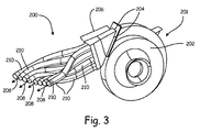
- FIG. 3 illustrates one example of an air flow assembly 200 for use with a pneumatic distribution system.
- Assembly 200 is removably coupled to an air source 201 (e.g. fan 36), having a housing 202, at a connection interface 204.
- housing 202 is substantially similar to housing 52 illustrated in FIG. 2 .
- connection interfaces e.g., interface 204
- connection interface 204 are herein illustrated as substantially flat or planar (also referred to as a connection plane- e.g., connection interface 204), in other examples a connection interface can be nonplanar.
- Assembly 200 includes a fixed, inflexible body portion 206, and a plurality of conduits 210 coupled to and extending from portion 206.
- Fixed portion 206 is coupled (removably or otherwise) on one end to housing 202 at connection interface 204 and, on a second end, to the plurality of conduits 212.
- Portion 206 and conduits 210 form a plurality of air flow paths for a respective air flow (generally represented by arrows 208) generated by source 201.
- Each air flow 208 forms a distribution stream.
- assembly 200 includes a plurality of inlet ports configured to receive the air, from the outlet of source 101 at connection plane 104, for the plurality of distribution streams.
- Each distribution stream is provide to an end point (e.g., a row unit, meter, etc.) using one or more conduits, or other element(s).
- conduits 210 convey the air to a volumetric metering system (e.g., manifold 24 of system 20 illustrated in FIG. 1 ).
- the inlet ports receive a section of the pressure gradient present at the outlet of source 201 such that the distribution streams having higher pressure drops receive higher air pressure from source 201 than distribution streams having lower pressure drops.
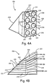
- FIGS. 4A and 4B illustrate one example of portion 206.
- portion 206 includes a plurality of inlet apertures 212.
- Portion 206 also includes a plurality of outlet apertures 214 at a conduit connection side or interface 222, and a plurality of passageways 224, 226, 228, and 230 formed between the inlet and outlet apertures.
- Outlet apertures 214 are configured to receive and fluidically couple to conduits 210 (not shown in FIG. 4 ). It is noted that while the example of FIG. 4 illustrates apertures arranged in a symmetrical four by two configuration for eight flow paths, portion 206 can be configured in another of a number of ways (including asymmetrically), for any number of flow paths.
- fixed portion 206 is configured such that the air from the air source outlet is segmented at the connection interface 204. That is, the inlet ports formed by apertures 212 are located at, or in close proximity to connection interface 204, and thus the air source outlet.
- This example configuration advantageously obtains air flow streams with a maximum, or near maximum, pressure differential between lines. That is, this configuration utilizes the pressure gradient at the air source outlet to distribution streams of differing air pressures.
- passageways 224 are formed by apertures 212 that are positioned to receive air from a relatively low pressure area (e.g., lower pressure area 64 shown in FIG. 2 ) and passageways 230 are formed by apertures 212 that are positioned to receive air from a relatively high pressure area (e.g., high pressure areas 60 shown in FIG. 2 ).
- Passageways 226 and 228 are positioned between passageways 224 and 230, and are configured to receive air from pressure areas that are between the low and high pressure areas.
- passageways 230 each have a substantially similar air pressure, which is greater than the air pressure in passageways 228.
- passageways 228 each have a substantially similar air pressure, which is greater than the air pressure in passageways 226.
- passageways 226 each have a substantially similar air pressure, which is greater than the air pressure in passageways 224.
- the passageways 224, 226, 228, and 230 that form the inlets to the distribution streams are arranged in continuum with passageways 224 receive the lowest pressure, passageways 230 receive the highest pressure, and passageways 226 and 228 are arranged in the continuum between the lowest and highest pressures.
- conduits 212 are connected to portion 206 based on the relative pressure drops in the distribution streams provided by those conducts.
- conduits 212 are connected to portion 206 such that longer distribution lines receive air from the outer diameter of source 201 (i.e., air with the highest dynamic pressure).
- the shortest distribution lines receive air from an area of the air source outlet that is closest to the fan axis (i.e., air with the lowest dynamic pressure).
- the coefficient of variation between the distribution line air pressures can be adjusted by the position of the inlet ports relative to the outlet pressure gradient and/or the size of the inlet ports. For example, an air seeder implementation with a smaller distribution line length variation (i.e., a shorter implement width) utilizes a smaller pressure variation between lines than an air seeder implementation with a larger distribution line length variation.
- configuring the distribution lines to receive air flows from the air source at different pressure values facilitates substantially balanced outlet pressures and flow rates among different distribution line lengths without increasing power consumption by the air source.
- the example air flow assembly can reduce space requirements compared to a large plenum box, as discussed above.
- air source connection interface 204 is oriented at an angle with respect to a conduit connection interface 222.
- interfaces 204 and 222 can be substantially parallel to one another.
- FIGS. 5A-5D illustrate another example of a fixed portion 240 for an air flow assembly.
- Fixed portion 240 comprises eight air flow paths for respective air flows (generally represented in FIG. 5 by arrows 208), arranged in a "T-shaped" orientation.
- the T-shaped orientation comprises of a four by one arrangement 241 coupled to a two by two arrangement 243.
- the fixed portion 240 comprises an air source connection interface or plane 204 configured to couple to an air source, and a conduit connection interface or plane 222 configured to couple to a plurality of conduits (not shown in FIG. 5 ).
- portion 240 comprises a plurality of passageways 242, 244, and 246 from between corresponding inlet and outlet apertures.
- the inlet apertures at air source connection interface 204 are substantially rectangular in shape, and have differing sizes. In another example, the inlet apertures can be substantially cylindrical and/or have similar sizes.
- FIGS. 5C and 5D which are side and top views of portion 240, respectively, passageways 242, 244, and 246 are shown in phantom.
- a plurality of different inlet pressure zones present along connection interface 204 are utilized to form air flows 208 of differing pressures.
- the highest pressure air flows 208 originate from connection ports 246, and the lowest pressure air flow 208 originate from passageways 242.
- conduits 210 are formed of flexible material(s) such that they can be maneuvered around structural or other components of the agricultural vehicle (i.e., seeder 10).
- conduits 210 comprise a substantially rigid portions movably coupled together by a plurality of joints.
- FIGS. 6A-6C illustrate another example of an air flow assembly 300 coupled to an air source 301 (e.g., fan 36), having a housing 302, at an air source connection interface 352.
- Assembly 300 includes a fixed portion 350 coupled to a plurality of conduits 362 at a conduit connection interface 352.
- Air source 301 in one example, is substantially similar to source 36.
- fixed portion 350 comprises a plurality of passageways 354, 356, 358, and 360 that separate air flows (generally represented by arrows 308) at or in close proximity to the air source outlet at interface 352, where the pressure gradient is greatest.
- Passageways 354 draw air from the air source outlet that has a relative highest pressure
- passageways 360 draw air from the air source outlet that has the relative lowest pressure.
- the inlet apertures to passageways 354, 356, 358, and 360 are located along or in close proximity to interface 352.
- the inlet apertures have different cross-sectional areas.
- the cross-sectional areas can be substantially similar.
- the sizes of each inlet aperture can be configured based on the require air flow and pressure drops in the distribution lines.
- FIGS. 7A-7D (collectively referred to as FIG. 7 ) illustrate another example of an air flow assembly 400 configured to be coupled to an air source (e.g., fan 36).
- FIGS. 7A and 7B are a side view and cross-sectional naval view, respectively.
- FIGS. 7C and 7D are end and exploded views, respectively.
- assembly 400 includes a mounting body 402 for mounting to the air source at an air source connection interface 404 and a conduit interface plate 406 configured to receive a plurality of conduits (not shown in FIG. 7 ) that form air flow paths for respective air flows (generally represented by arrows 408).
- Assembly 400 includes a premixing chamber or space 410 between the connection interface 404 and inlet ports 412, 414, and 416 for the distribution streams.
- premixing chamber 410 facilitates premixing of the air from the air source outlet before entering, and being segmented by, ports 412, 414, and 416.
- This premixing reduces the pressure gradient to some extent (i.e., the pressures in the distribution streams are somewhat equalized).
- the pressure gradient at interface 404 is different than the pressure gradient at ports 412, 414, and 416.
- the amount that the pressure gradient is reduced can depend on the size of the pressure chamber 410 and distance between connection interface 404 and ports 412, 414, and 416.
- Premixing can be advantageous in implementations with a smaller distribution line length variation. To illustrate, in one example, the difference in air pressure between ports 412 and 416 is less than the difference in air pressure between passageways 226 and 228 in FIG. 4 .
- inlet ports 412, 414, and 416 are arranged in a symmetrical three by three configuration. Some or all of the inlet ports are fluidically coupled to conduits that provide product distribution lines. One or more of the inlet ports can be fluidically coupled to conduit(s) that provide air for other purposes.
- inlet port 418 comprises a tank pressurization port that is coupled to a conduit that provides pressuring air for a tank (e.g,. a seed tank, etc.). It is noted that other symmetrical or nonsymmetrical configurations can be utilized.
- assembly 400 comprises one or more sealing interfaces, formed by gasket(s), o-ring(s), and/or another suitable sealing mechanism(s).
- sealing interfaces 420 and 422, such as rubber gaskets provided between body 402 and the air source, and between body 402 and plate 406, respectively.
- a cover 424 is removably coupled to body 402 using a latch 426. Cover 424 is positioned to retain plate 406 proximate premixing chamber 410.
- an orifice plate 428 is positioned proximate conduit connection plate 406.
- Orifice plate 428 includes a plurality orifices aligned with the ports formed in plate 406. Some or all of the orifices have a substantially similar size in relation to the cross-section of the ports in plate 406. However, one or more of the orifices in orifice plate 428 can have a reduced size to restrict the air flow through the corresponding port in plate 406.
- an orifice 430 in plate 428 has a substantially smaller size than the corresponding orifice 432 in plate 406 to form pressurizing port 418.
- orifice plate 428 is formed of metal (e.g., steel, etc.).
- the other components of assembly 400 can be formed of any suitable material(s) as well.
- body 402 conduit connection plate 406 and/or cover 424 can also be formed of plastic (e.g., polyethylene, etc.) and/or metal.
- each of the air flow assemblies illustrated in FIGS. 3-7 are configured for use with a same or similar air source.
- the air flow assemblies can be easily interchanged at the air source connection plane (e.g., interfaces 104, 204, 352, 404, etc.) based on the particular application and distribution requirements (e.g., different crops or seeding rates, different seeding implement widths, etc.).
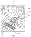
- FIG. 8 illustrates a bottom perspective view of a pneumatic distribution system 500 mounted on an agricultural vehicle 502, in one example.
- System 500 includes a plurality of air sources 504 and 506 (e.g., centrifugal fans).
- a first air flow assembly 508 is coupled to air source 504 and a second air flow assembly 510 is coupled to air source 506.
- a first set of conduits 512 couple each air flow assembly 508, 510 to a metering system 514.
- the conduits coupled to assembly 508 have been omitted for illustration purposes.
- a second set of conduits 516 provide distribution paths from the metering system 514.
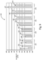
- FIG. 9 is a bar chart illustrating flow rates, in cubic feet per minute (CFM), for several example pneumatic distribution systems that utilize a substantially similar air source.
- a first group of bars 602 represent a first distribution line length (e.g., fifty eight foot distribution line from fan outlet to row unit)
- a second group of bars 604 represent a second distribution line length (e.g., forty nine foot distribution line from fan outlet to row unit)
- a third group of bars 606 represent a third distribution line length (e.g., thirty seven foot distribution line from fan outlet to row unit)
- a fourth group of bars 608 represent a fourth distribution line length (e.g., twenty three foot distribution line from fan outlet to row unit).
- Each group of bars includes a first bar 610 and a second bar 630.
- the first bar 610 represents a first distribution system that utilizes a large plenum box that equalizes air pressures at the distribution line inlets through substantial mixing of the air prior to segmentation into the individual distribution lines.
- the second bar 630 represents a second distribution system that utilizes an air flow assembly substantially similar to the example shown in FIG. 3 .
- first distribution system exhibits a greater difference in flow rate between the longest and shorts distribution lines. That is, the flow rate in the shortest distribution line is approximately sixty-three percent of the flow rate in the longest distribution line. However, the flow rates in the second distribution system is significantly more similar (i.e., flow rates in the shortest distribution lines are eighty-six percent compared to the longest distribution lines). Additionally, compared to the first distribution system, the example second distribution system can reduce pressure loss by approximately forty percent, and reduce housing cut-off flow circulation, which can improve fan efficiency.
Landscapes
- Life Sciences & Earth Sciences (AREA)
- Soil Sciences (AREA)
- Environmental Sciences (AREA)
- Engineering & Computer Science (AREA)
- Mechanical Engineering (AREA)
- Fertilizing (AREA)
- Sowing (AREA)
- Filling Or Discharging Of Gas Storage Vessels (AREA)
- Multiple-Way Valves (AREA)
Abstract
Description
- The present description relates to agricultural equipment. More specifically, but not by limitation, the present description relates to a pneumatic distribution system for agricultural vehicles.
- Agricultural vehicles or other equipment often include a pneumatic distribution system for distributing product to one or more end points. In an air seeder, for example, an air distribution system comprises an air source that provides air flow to a plurality of distribution lines or runs. A metering system, such as a volumetric meter, can be used to meter product (e.g., seed, fertilizer, etc.) into the air flow. In one example, the air distribution system employs a plenum that couples the plurality of distribution lines to the output of the air source in a manner that provides equal air pressure to each distribution line.
- The discussion above is merely provided for general background information and is not intended to be used as an aid in determining the scope of the claimed subject matter.
- A pneumatic distribution system for pneumatically distributing material in an agricultural vehicle is described. In one example, the pneumatic distribution system comprises an air source having an outlet with different air pressures defining a pressure gradient across the outlet, and a plurality of inlet ports configured to receive air from the outlet for a plurality of distribution streams, comprising at least a first distribution stream with a first pressure loss value and a second distribution stream with a second pressure loss value that is greater than the first pressure loss value. The inlet ports for the first and second distribution streams are located relative to the pressure gradient such that the second distribution stream receives a higher air pressure than the first distribution stream.
- This Summary is provided to introduce a selection of concepts in a simplified form that are further described below in the Detailed Description. This Summary is not intended to identify key features or essential features of the claimed subject matter, nor is it intended to be used as an aid in determining the scope of the claimed subject matter. The claimed subject matter is not limited to implementations that solve any or all disadvantages noted in the background.
-
-
FIG. 1 illustrates a side view of one example of an agricultural vehicle with a pneumatic distribution system for pneumatically distributing agricultural product. -
FIG. 2 illustrates one example of an air source. -
FIG. 3 illustrates an example air flow assembly for a pneumatic distribution system. -
FIGS. 4A and 4B illustrate an example air flow assembly for a pneumatic distribution system. -
FIGS. 5A-5D illustrate an example air flow assembly for a pneumatic distribution system. -
FIGS. 6A-6C illustrate an example air flow assembly for a pneumatic distribution system. -
FIGS. 7A-7D illustrate an example air flow assembly for a pneumatic distribution system. -
FIG. 8 illustrates a bottom perspective view of a pneumatic distribution system mounted on an agricultural vehicle, in one example. -
FIG. 9 is a bar chart illustrating flow rates for several example pneumatic distribution systems. -
FIG. 1 illustrates a side view of one example of an agricultural vehicle with a pneumatic distribution system for pneumatically (e.g., air or other gas) distributing agricultural product in the form of particulate material (e.g. seed, fertilizer, etc.). In the illustrated example, the vehicle comprises anair seeder 10 that pneumatically delivers seed and/or fertilizer to ground engaging openers. Of course, a pneumatic distribution system can be utilized with other types of vehicles as well. - Seeder 10 comprises a
seed cart 11 towed between, for example, a tractor (not shown) and a tilling implement 12. Theseed cart 11 also includes aframe 14 to whichproduct tanks 16 andwheels 18 are mounted. Eachproduct tank 16 includes an associatedmetering system 20 at its lower end for controlled feeding of a product into apneumatic distribution system 22. Themetering system 20, is adjacent to a discharge end of aproduct tank 16. The tilling implement 12, towed behind theseed cart 11, comprises aframe 30 to whichground openers 32 are mounted. Incorporation of seed row finishing equipment, such asclosing wheels 34, can also be utilized, in one example. -
Pneumatic distribution system 22 includes anair source 36, such as, but not limited to, a fan, blower, compressor, and/or pump. In the illustrated example,air source 36 comprises a centrifugal fan (also referred to as centrifugal fan 36) connected to aplenum 38, which in turn is connected through one or more conduits to one or moreprimary distribution manifolds 24. Eachmanifold 24 is configured to receive product from one ofproduct tanks 16 that is metered throughmetering system 20. In one example,metering system 20 comprises one or more volumetric meters that volumetrically meters product intodistribution system 22. - Each individual passage in the
primary distribution manifold 24 is connected by adistribution line 40 to ariser tube 42. However, while only oneriser tube 42 is shown inFIG. 1 , in another example,multiple riser tubes 42 can be utilized. Eachriser tube 42 is, in turn, coupled to asecondary distribution header 44. One ormore distribution lines 46 connect thesecondary distribution header 44 to seed boots (not shown) mounted on theground openers 32 to deliver product (e.g. seed or fertilizer) to a furrow formed by theopeners 32. - While
seeder 10 ofFIG. 1 is shown as aseparate seed cart 11 connected to tilling implement 12, in one example, theproduct tank 16,metering system 20 andpneumatic distribution system 22 can be mounted on the same frame as theground openers 32. Further, whileair source 36 is described herein as providing a source of air,source 36 can be configured to provide a flow of other types of distribution gasses as well. -
FIG. 2 illustrate one example ofcentrifugal fan 36. As shown inFIG. 2 , which is a perspective offan 36, aninlet port 50 receives air (generally represented by arrow 51), which is moved through ahousing 52 to anoutlet 54 by impellers or rotating blades that rotate about afan axis 56. - The air exits outlet 54 (generally represented by arrow 55) with different air pressures that define a pressure gradient across
outlet 54. That is, depending on the configuration of the fan, some areas or pressure zones have higher pressures than other areas inoutlet 54. In the examplecentrifugal fan 36, a pressure gradient is defined along apressure axis 58, wherehigh pressure areas 60 are located near an outer periphery 62 (i.e., further away from axis 56) andlow pressure areas 64 are located more closely toaxis 56. While the air source is illustrated as a centrifugal fan inFIGS. 1 and2 , other types of air sources can be utilized that have pressure gradients. - In one example air distribution system design, a large plenum box is affixed to the outlet of the air source to mitigate the different pressures along the pressure gradient, thereby providing substantially equal pressures to the distribution paths. For example, the plenum box can be configured such that static pressure at each primary outlet of the plenum is substantially equal.
- However, in some applications, the lengths of the distribution lines are significantly different. For example, referring again to
air seeder 10, somedistribution lines 40 have different lengths from theair source 36 depending on the particular endpoints (e.g., row unit). In one example,distribution lines 40 can vary up to 30 feet, or more. For instance, a distribution line to an inner row unit can be 30 feet long, whereas a distribution line to an outer row unit can be 50 feet long. This, of course, is an example only. - In any case, some
distribution lines 40 have different pressure drops due to the length differences, or other factors. This results in an uneven pressure loss, and different volumetric flow rates at the end points, which can affect seed spacing, yields, etc. In one attempt to provide equal flow rates to all row units (i.e., to limit row to row variation in seed application), undesired pressure loss variation between distribution lines is reduced by restricting flow in the shorter lines in order to equalize the pressure loss across all distribution lines. For example, in one implementation a restricting damper, plate, orifice, or other device is placed in the shorter distribution lines so that the shorter distribution lines have a similar pressure drop compared to the longer distribution lines. However, such a configuration restricts commodity conveyance, decreases the overall efficiency of the fan, and increases the overall energy consumption and requirements to achieve a desired volumetric flow rate. - The present disclosure provides a pneumatic distribution system for pneumatically distributing material in an agricultural vehicle. The pneumatic distribution system comprises an air source having an outlet with different air pressures defining a pressure gradient across the outlet, and a plurality of inlet ports configured to receive air from the outlet for a plurality of distribution streams, comprising at least a first distribution stream with a first pressure loss value and a second distribution stream with a second pressure loss value that is greater than the first pressure loss value.
- In one example, the inlet ports for the first and second distribution streams are located relative to the pressure gradient such that the second distribution stream receives a higher air pressure than the first distribution stream. In one example, the air pressure at the inlet for the second distribution stream is at least two times greater than the air pressure at the inlet for the first distribution stream. In one example, the air pressure at the inlet for the second distribution stream is at least three times greater than the air pressure at the inlet for the first distribution stream. In one example, the air pressure at the inlet for the second distribution stream is at least four times greater than the air pressure at the inlet for the first distribution stream. In one example, the air pressure at the inlet for the second distribution stream is at least five times greater than the air pressure at the inlet for the first distribution stream.
- In one example, the plurality of distribution streams comprises a plurality of lines, or runs, to row units on an air seeder. As used herein, a "line" refers to a channel or path to an end point. For instance, a line can provide an air flow path to one or more row units. Further, a line can be formed by a plurality of separate elements connected together. For instance, a given line can comprise separate conduit(s), tube(s), manifold(s), meter(s), row unit(s), etc., coupled together to form a single distribution path from the air source to an end point.
-
FIG. 3 illustrates one example of anair flow assembly 200 for use with a pneumatic distribution system.Assembly 200 is removably coupled to an air source 201 (e.g. fan 36), having ahousing 202, at aconnection interface 204. In one example,housing 202 is substantially similar tohousing 52 illustrated inFIG. 2 . While connection interfaces (e.g., interface 204) are herein illustrated as substantially flat or planar (also referred to as a connection plane- e.g., connection interface 204), in other examples a connection interface can be nonplanar. -
Assembly 200 includes a fixed,inflexible body portion 206, and a plurality ofconduits 210 coupled to and extending fromportion 206.Fixed portion 206 is coupled (removably or otherwise) on one end tohousing 202 atconnection interface 204 and, on a second end, to the plurality ofconduits 212.Portion 206 andconduits 210 form a plurality of air flow paths for a respective air flow (generally represented by arrows 208) generated bysource 201. Eachair flow 208 forms a distribution stream. - As discussed in further detail below,
assembly 200 includes a plurality of inlet ports configured to receive the air, from the outlet of source 101 at connection plane 104, for the plurality of distribution streams. Each distribution stream is provide to an end point (e.g., a row unit, meter, etc.) using one or more conduits, or other element(s). In one example,conduits 210 convey the air to a volumetric metering system (e.g.,manifold 24 ofsystem 20 illustrated inFIG. 1 ). - In the illustrated example, the inlet ports receive a section of the pressure gradient present at the outlet of
source 201 such that the distribution streams having higher pressure drops receive higher air pressure fromsource 201 than distribution streams having lower pressure drops. -
FIGS. 4A and 4B (collectively referred to asFIG. 4 ) illustrate one example ofportion 206. At theconnection interface 204,portion 206 includes a plurality ofinlet apertures 212.Portion 206 also includes a plurality ofoutlet apertures 214 at a conduit connection side orinterface 222, and a plurality ofpassageways Outlet apertures 214 are configured to receive and fluidically couple to conduits 210 (not shown inFIG. 4 ). It is noted that while the example ofFIG. 4 illustrates apertures arranged in a symmetrical four by two configuration for eight flow paths,portion 206 can be configured in another of a number of ways (including asymmetrically), for any number of flow paths. - In the illustrated example, fixed
portion 206 is configured such that the air from the air source outlet is segmented at theconnection interface 204. That is, the inlet ports formed byapertures 212 are located at, or in close proximity toconnection interface 204, and thus the air source outlet. This example configuration advantageously obtains air flow streams with a maximum, or near maximum, pressure differential between lines. That is, this configuration utilizes the pressure gradient at the air source outlet to distribution streams of differing air pressures. - As shown in
FIGS. 3 and4 ,passageways 224 are formed byapertures 212 that are positioned to receive air from a relatively low pressure area (e.g.,lower pressure area 64 shown inFIG. 2 ) andpassageways 230 are formed byapertures 212 that are positioned to receive air from a relatively high pressure area (e.g.,high pressure areas 60 shown inFIG. 2 ).Passageways passageways passageways 230 each have a substantially similar air pressure, which is greater than the air pressure inpassageways 228. Likewise,passageways 228 each have a substantially similar air pressure, which is greater than the air pressure inpassageways 226. Likewise,passageways 226 each have a substantially similar air pressure, which is greater than the air pressure inpassageways 224. As such, in the illustrated example, thepassageways passageways 224 receive the lowest pressure,passageways 230 receive the highest pressure, andpassageways - Accordingly,
conduits 212 are connected toportion 206 based on the relative pressure drops in the distribution streams provided by those conducts. For example,conduits 212 are connected toportion 206 such that longer distribution lines receive air from the outer diameter of source 201 (i.e., air with the highest dynamic pressure). The shortest distribution lines, on the other hand, receive air from an area of the air source outlet that is closest to the fan axis (i.e., air with the lowest dynamic pressure). The coefficient of variation between the distribution line air pressures can be adjusted by the position of the inlet ports relative to the outlet pressure gradient and/or the size of the inlet ports. For example, an air seeder implementation with a smaller distribution line length variation (i.e., a shorter implement width) utilizes a smaller pressure variation between lines than an air seeder implementation with a larger distribution line length variation. - Accordingly, in the illustrated example, configuring the distribution lines to receive air flows from the air source at different pressure values facilitates substantially balanced outlet pressures and flow rates among different distribution line lengths without increasing power consumption by the air source. Additionally, the example air flow assembly can reduce space requirements compared to a large plenum box, as discussed above.
- Further, it is noted that the length of
passageways portion 206 can be the same or different. In the example ofFIG. 4 , airsource connection interface 204 is oriented at an angle with respect to aconduit connection interface 222. In another example, interfaces 204 and 222 can be substantially parallel to one another. -
FIGS. 5A-5D (collectively referred to asFIG. 5 ) illustrate another example of a fixedportion 240 for an air flow assembly.Fixed portion 240 comprises eight air flow paths for respective air flows (generally represented inFIG. 5 by arrows 208), arranged in a "T-shaped" orientation. The T-shaped orientation comprises of a four by onearrangement 241 coupled to a two by twoarrangement 243. The fixedportion 240 comprises an air source connection interface orplane 204 configured to couple to an air source, and a conduit connection interface orplane 222 configured to couple to a plurality of conduits (not shown inFIG. 5 ). - As shown in
FIG. 5B ,portion 240 comprises a plurality ofpassageways source connection interface 204 are substantially rectangular in shape, and have differing sizes. In another example, the inlet apertures can be substantially cylindrical and/or have similar sizes. - In
FIGS. 5C and 5D , which are side and top views ofportion 240, respectively,passageways connection interface 204 are utilized to form air flows 208 of differing pressures. In one example, the highest pressure air flows 208 originate fromconnection ports 246, and the lowestpressure air flow 208 originate frompassageways 242. - Referring again to
FIG. 3 , in one example,conduits 210 are formed of flexible material(s) such that they can be maneuvered around structural or other components of the agricultural vehicle (i.e., seeder 10). In one example,conduits 210 comprise a substantially rigid portions movably coupled together by a plurality of joints. -
FIGS. 6A-6C (collectively referred to asFIG. 6 ) illustrate another example of anair flow assembly 300 coupled to an air source 301 (e.g., fan 36), having ahousing 302, at an airsource connection interface 352.Assembly 300 includes a fixedportion 350 coupled to a plurality ofconduits 362 at aconduit connection interface 352.Air source 301, in one example, is substantially similar tosource 36. - As shown in
FIGS. 6B and 6C , which illustrate front and rear perspective views, respectively, fixedportion 350 comprises a plurality ofpassageways interface 352, where the pressure gradient is greatest. -
Passageways 354 draw air from the air source outlet that has a relative highest pressure, andpassageways 360 draw air from the air source outlet that has the relative lowest pressure. The inlet apertures topassageways -
FIGS. 7A-7D (collectively referred to asFIG. 7 ) illustrate another example of anair flow assembly 400 configured to be coupled to an air source (e.g., fan 36).FIGS. 7A and 7B are a side view and cross-sectional perspectival view, respectively.FIGS. 7C and7D are end and exploded views, respectively. - As shown in
FIG. 7 ,assembly 400 includes a mountingbody 402 for mounting to the air source at an airsource connection interface 404 and aconduit interface plate 406 configured to receive a plurality of conduits (not shown inFIG. 7 ) that form air flow paths for respective air flows (generally represented by arrows 408).Assembly 400 includes a premixing chamber orspace 410 between theconnection interface 404 andinlet ports - In the illustrated example, premixing
chamber 410 facilitates premixing of the air from the air source outlet before entering, and being segmented by,ports interface 404 is different than the pressure gradient atports pressure chamber 410 and distance betweenconnection interface 404 andports ports passageways FIG. 4 . - In the illustrated example,
inlet ports inlet port 418 comprises a tank pressurization port that is coupled to a conduit that provides pressuring air for a tank (e.g,. a seed tank, etc.). It is noted that other symmetrical or nonsymmetrical configurations can be utilized. - As shown in
FIG. 7D ,assembly 400 comprises one or more sealing interfaces, formed by gasket(s), o-ring(s), and/or another suitable sealing mechanism(s). For example, sealinginterfaces body 402 and the air source, and betweenbody 402 andplate 406, respectively. Acover 424 is removably coupled tobody 402 using alatch 426. Cover 424 is positioned to retainplate 406proximate premixing chamber 410. - In one example, an
orifice plate 428 is positioned proximateconduit connection plate 406.Orifice plate 428 includes a plurality orifices aligned with the ports formed inplate 406. Some or all of the orifices have a substantially similar size in relation to the cross-section of the ports inplate 406. However, one or more of the orifices inorifice plate 428 can have a reduced size to restrict the air flow through the corresponding port inplate 406. In the example ofFIG. 7D , anorifice 430 inplate 428 has a substantially smaller size than thecorresponding orifice 432 inplate 406 to form pressurizingport 418. - In one example,
orifice plate 428 is formed of metal (e.g., steel, etc.). The other components ofassembly 400 can be formed of any suitable material(s) as well. In one example,body 402conduit connection plate 406 and/or cover 424 can also be formed of plastic (e.g., polyethylene, etc.) and/or metal. - It is noted that, in one example, each of the air flow assemblies illustrated in
FIGS. 3-7 are configured for use with a same or similar air source. As such, the air flow assemblies can be easily interchanged at the air source connection plane (e.g., interfaces 104, 204, 352, 404, etc.) based on the particular application and distribution requirements (e.g., different crops or seeding rates, different seeding implement widths, etc.). -
FIG. 8 illustrates a bottom perspective view of apneumatic distribution system 500 mounted on anagricultural vehicle 502, in one example.System 500 includes a plurality ofair sources 504 and 506 (e.g., centrifugal fans). A firstair flow assembly 508 is coupled toair source 504 and a secondair flow assembly 510 is coupled toair source 506. A first set ofconduits 512 couple eachair flow assembly metering system 514. InFIG. 8 , the conduits coupled toassembly 508 have been omitted for illustration purposes. A second set ofconduits 516 provide distribution paths from themetering system 514. - For sake of illustration, but not by limitation,
FIG. 9 is a bar chart illustrating flow rates, in cubic feet per minute (CFM), for several example pneumatic distribution systems that utilize a substantially similar air source. A first group ofbars 602 represent a first distribution line length (e.g., fifty eight foot distribution line from fan outlet to row unit), a second group ofbars 604 represent a second distribution line length (e.g., forty nine foot distribution line from fan outlet to row unit), a third group ofbars 606 represent a third distribution line length (e.g., thirty seven foot distribution line from fan outlet to row unit), and a fourth group ofbars 608 represent a fourth distribution line length (e.g., twenty three foot distribution line from fan outlet to row unit). - Each group of bars includes a
first bar 610 and asecond bar 630. Thefirst bar 610 represents a first distribution system that utilizes a large plenum box that equalizes air pressures at the distribution line inlets through substantial mixing of the air prior to segmentation into the individual distribution lines. Thesecond bar 630 represents a second distribution system that utilizes an air flow assembly substantially similar to the example shown inFIG. 3 . - As shown in
FIG. 9 , first distribution system exhibits a greater difference in flow rate between the longest and shorts distribution lines. That is, the flow rate in the shortest distribution line is approximately sixty-three percent of the flow rate in the longest distribution line. However, the flow rates in the second distribution system is significantly more similar (i.e., flow rates in the shortest distribution lines are eighty-six percent compared to the longest distribution lines). Additionally, compared to the first distribution system, the example second distribution system can reduce pressure loss by approximately forty percent, and reduce housing cut-off flow circulation, which can improve fan efficiency. - It should also be noted that the different examples described herein can be combined in different ways. That is, parts of one or more examples can be combined with parts of one or more other examples. All of this is contemplated herein.
- Example 1 is a pneumatic distribution system for pneumatically distributing material in an agricultural vehicle, the pneumatic distribution system comprising an air source having an outlet with different air pressures defining a pressure gradient across the outlet, and a plurality of inlet ports configured to receive air from the outlet for a plurality of distribution streams, comprising at least a first distribution stream with a first pressure loss value and a second distribution stream with a second pressure loss value that is greater than the first pressure loss value, wherein the inlet ports for the first and second distribution streams are located relative to the pressure gradient such that the second distribution stream receives a higher air pressure than the first distribution stream.
- Example 2 is the pneumatic distribution system of any or all previous examples, wherein the air source comprises a centrifugal fan.
- Example 3 is the pneumatic distribution system of any or all previous examples, wherein the air pressure at each inlet port is proportional to the pressure loss value of the corresponding distribution stream.
- Example 4 is the pneumatic distribution system of any or all previous examples, wherein the plurality of distribution streams comprise a plurality of lines that distribute air from the outlet to a plurality of end points.
- Example 5 is the pneumatic distribution system of any or all previous examples, wherein each of the plurality of inlet ports is configured to receive air along the pressure gradient such that, at the plurality of end points, the air flow rates in the plurality of distribution streams are substantially equal.
- Example 6 is the pneumatic distribution system of any or all previous examples, wherein each of the lines comprises a separate conduit fluidically coupled to one of the inlet ports.
- Example 7 is the pneumatic distribution system of any or all previous examples, wherein the agricultural vehicle comprises an air seeder, and the plurality of end points comprise row units on the air seeder.
- Example 8 is the pneumatic distribution system of any or all previous examples, wherein each conduit couples the respective inlet port to a metering system configured to meter material into the respective distribution stream.
- Example 9 is the pneumatic distribution system of any or all previous examples, wherein the metering system comprises a volumetric meter.
- Example 10 is the pneumatic distribution system of any or all previous examples, wherein the inlet ports for the first and second distribution streams have a substantially similar cross-sectional area.
- Example 11 is the pneumatic distribution system of any or all previous examples, wherein the inlet ports for the first and second distribution streams have different cross-sectional areas.
- Example 12 is the pneumatic distribution system of any or all previous examples, wherein the plurality of inlet ports are fluidically coupled directly to the outlet.
- Example 13 is the pneumatic distribution system of any or all previous examples, wherein the plurality of inlet ports are spaced apart from the outlet.
- Example 14 is the pneumatic distribution system of any or all previous examples further comprising a plenum chamber that is located between the outlet and the plurality of inlet ports and configured to receive the air from the outlet for the plurality of distribution streams.
- Example 15 is the pneumatic distribution system of any or all previous examples, wherein the inlet ports for the first and second distribution streams are fluidically coupled to the plenum chamber.
- Example 16 is an agricultural implement comprising a product source, a metering system configured to meter product from the product source, and a pneumatic distribution system configured to pneumatically distribute the metered product to a plurality of end points on the agricultural implement, the pneumatic distribution system comprising an air source having an outlet with different air pressure zones defining a pressure gradient across the outlet, and a plurality of distribution lines configured to provide air streams to the plurality of end points, the plurality of distribution lines comprising at least a first distribution line and a second distribution line that has longer length than the first distribution line, wherein the second distribution line is configured to receive higher air pressure compared to the first distribution line.
- Example 17 is the agricultural implement of any or all previous examples, wherein the agricultural vehicle comprises an air seeder, the air source comprises a centrifugal fan, and the plurality of end points comprise row units on the air seeder.
- Example 18 is the agricultural implement of any or all previous examples, wherein the outlet comprises a fan axis, and an inlet for the second distribution line is located further away from the fan axis than an inlet for the first distribution line.
- Example 19 is an agricultural pneumatic distribution system comprising a fan assembly having an outlet, and a plurality of conduits, each configured to receive an air stream for conveying an agricultural material to an end point, wherein a first one of conduits is positioned such that it receives a first air stream from a high pressure area of the outlet and a second one of the conduits is positioned such that it receives a second air stream from a low pressure area along the pressure gradient, wherein the first conduit is associated with a distribution line having a higher pressure drop than a distribution line associated with the second conduit.
- Example 20 is the pneumatic distribution system of any or all previous examples, wherein the fan assembly comprises a centrifugal fan having a fan axis, and wherein a first inlet for the first conduit is located further away from the fan axis than a second inlet for the second conduit.
- Although the subject matter has been described in language specific to structural features and/or methodological acts, it is to be understood that the subject matter defined in the appended claims is not necessarily limited to the specific features or acts described above. Rather, the specific features and acts described above are disclosed as example forms of implementing the claims.
Claims (12)
- A pneumatic distribution system (22) for pneumatically distributing material in an agricultural vehicle (10), the pneumatic distribution system comprising:an air source (36) having an outlet (54) with different air pressures defining a pressure gradient across the outlet (54); anda plurality of inlet ports configured to receive air from the outlet (54) for a plurality of distribution streams, comprising at least a first distribution stream with a first pressure loss value and a second distribution stream with a second pressure loss value that is greater than the first pressure loss value, wherein the inlet ports for the first and second distribution streams are located relative to the pressure gradient such that the second distribution stream receives a higher air pressure than the first distribution stream.
- The pneumatic distribution system (22) of claim 1, wherein the air source (36) comprises a centrifugal fan (36).
- The pneumatic distribution system (22) of claim 1 or 2, wherein the air pressure at each inlet port is proportional to the pressure loss value of the corresponding distribution stream, and wherein the plurality of distribution streams comprise a plurality of lines (40) that distribute air from the outlet (54) to a plurality of end points.
- The pneumatic distribution system (22) of one of the claims 1 to 3, wherein each of the plurality of inlet ports is configured to receive air along the pressure gradient such that, at the plurality of end points, the air flow rates in the plurality of distribution streams are substantially equal.
- The pneumatic distribution system (22) of one of the claims 3 or 4, wherein each of the lines (40) comprises a separate conduit fluidically coupled to one of the inlet ports and coupleable to a metering system configured to meter material into the respective distribution stream.
- The pneumatic distribution system (22) of one of the claims 1 to 5, wherein the plurality of inlet ports are fluidically coupled directly to the outlet (54).
- The pneumatic distribution system (22) of one of the claims 1 to 6, wherein the plurality of inlet ports are spaced apart from the outlet (54).
- The pneumatic distribution system (22) of one of the claims 1 to 7, and further comprising a plenum chamber that is located between the outlet (54) and the plurality of inlet ports and configured to receive the air from the outlet (54) for the plurality of distribution streams.
- The pneumatic distribution system (22) of claim 8, wherein the inlet ports for the first and second distribution streams are fluidically coupled to the plenum chamber.
- An agricultural vehicle (10) comprising:a product source; a metering system configured to meter product from the product source; and a pneumatic distribution system (22) according to one of the claims 1 to 9, wherein the plurality of distribution streams comprising at least a first distribution line and a second distribution line that has longer length than the first distribution line, wherein the second distribution line is configured to receive higher air pressure compared to the first distribution line.
- The agricultural vehicle (10) of claim 10, wherein the agricultural vehicle (10) comprises an air seeder, the air source comprises a centrifugal fan, and the plurality of end points comprise row units on the air seeder.
- The agricultural implement of claim 11, wherein the centrifugal fan (36) comprises a fan axis (56), and an inlet for the second distribution line is located further away from the fan axis (56) than an inlet for the first distribution line.
Applications Claiming Priority (1)
| Application Number | Priority Date | Filing Date | Title |
|---|---|---|---|
| US14/861,374 US9969569B2 (en) | 2015-09-22 | 2015-09-22 | Agricultural vehicle pneumatic distribution system |
Publications (2)
| Publication Number | Publication Date |
|---|---|
| EP3146827A1 true EP3146827A1 (en) | 2017-03-29 |
| EP3146827B1 EP3146827B1 (en) | 2018-06-27 |
Family
ID=56979408
Family Applications (1)
| Application Number | Title | Priority Date | Filing Date |
|---|---|---|---|
| EP16189578.4A Active EP3146827B1 (en) | 2015-09-22 | 2016-09-20 | Pneumatic distribution system and vehicle with such |
Country Status (5)
| Country | Link |
|---|---|
| US (5) | US9969569B2 (en) |
| EP (1) | EP3146827B1 (en) |
| AU (2) | AU2016219595A1 (en) |
| BR (1) | BR102016018888A2 (en) |
| CA (2) | CA3222605A1 (en) |
Cited By (1)
| Publication number | Priority date | Publication date | Assignee | Title |
|---|---|---|---|---|
| RU2684310C1 (en) * | 2018-07-11 | 2019-04-05 | Федеральное государственное бюджетное образовательное учреждение высшего образования "Кубанский государственный аграрный университет имени И.Т. Трубилина" | Machine for applying mineral fertilizers |
Families Citing this family (23)
| Publication number | Priority date | Publication date | Assignee | Title |
|---|---|---|---|---|
| US10306825B2 (en) | 2014-11-04 | 2019-06-04 | Cnh Industrial Canada, Ltd. | Air distribution system for a pneumatic conveying system |
| US9969569B2 (en) | 2015-09-22 | 2018-05-15 | Deere & Company | Agricultural vehicle pneumatic distribution system |
| US9902571B2 (en) * | 2016-02-29 | 2018-02-27 | Cnh Industrial Canada, Ltd. | Air distribution system for a pneumatic conveying system |
| US10244673B2 (en) * | 2016-08-30 | 2019-04-02 | Cnh Industrial Canada, Ltd. | Agricultural air cart blower fan arrangement |
| US10427113B2 (en) * | 2017-07-18 | 2019-10-01 | Cnh Industrial Canada, Ltd. | Horizontal product distribution system using static baffles in a distributor |
| US11343958B2 (en) * | 2018-08-27 | 2022-05-31 | Lynx Ag, LLC | High flow fertilizer/air meter with secondary nozzling |
| US11547038B2 (en) | 2019-10-31 | 2023-01-10 | Deere & Company | Plenum for air seeding machine and method of use |
| PL4068937T3 (en) | 2019-12-05 | 2025-09-01 | Salford Group Inc. | Variable tillage implement |
| US11596095B2 (en) | 2019-12-24 | 2023-03-07 | Cnh Industrial America Llc | Particle delivery system of an agricultural row unit |
| US11553639B2 (en) | 2019-12-24 | 2023-01-17 | Cnh Industrial America Llc | Particle delivery system of an agricultural row unit |
| US11553638B2 (en) | 2019-12-24 | 2023-01-17 | Cnh Industrial America Llc | Particle delivery system of an agricultural row unit |
| US11523555B2 (en) | 2019-12-24 | 2022-12-13 | Cnh Industrial America Llc | Particle delivery system of an agricultural row unit |
| US11589500B2 (en) | 2019-12-24 | 2023-02-28 | Cnh Industrial America Llc | Particle delivery system of an agricultural row unit |
| US11582899B2 (en) | 2019-12-24 | 2023-02-21 | Cnh Industrial America Llc | Particle delivery system of an agricultural row unit |
| US11523556B2 (en) | 2019-12-24 | 2022-12-13 | Cnh Industrial America Llc | Particle delivery system of an agricultural row unit |
| US11564344B2 (en) | 2019-12-24 | 2023-01-31 | Cnh Industrial America Llc | Particle delivery system of an agricultural row unit |
| US11516958B2 (en) | 2019-12-24 | 2022-12-06 | Cnh Industrial America Llc | Particle delivery system of an agricultural row unit |
| US11564346B2 (en) | 2019-12-24 | 2023-01-31 | Cnh Industrial America Llc | Particle delivery system of an agricultural row unit |
| US11490558B2 (en) | 2019-12-24 | 2022-11-08 | Cnh Industrial America Llc | Particle delivery system of an agricultural row unit |
| US11483963B2 (en) | 2019-12-24 | 2022-11-01 | Cnh Industrial America Llc | Particle delivery system of an agricultural row unit |
| US12208974B2 (en) * | 2020-11-11 | 2025-01-28 | Main Tech Srl | Distribution apparatus for solid particles |
| CA3233369A1 (en) * | 2023-04-03 | 2025-06-23 | Bourgault Industries Ltd. | Flow control apparatus for agricultural product distribution system |
| US12557728B2 (en) * | 2023-08-17 | 2026-02-24 | Agco Corporation | Solid distribution systems for an agricultural spreader |
Citations (4)
| Publication number | Priority date | Publication date | Assignee | Title |
|---|---|---|---|---|
| GB2013464A (en) * | 1978-01-30 | 1979-08-15 | Amazonen Werke Dreyer H | A Machine for Distributing Granular or Particulate Material |
| EP0368022A2 (en) * | 1988-11-10 | 1990-05-16 | Amazonen-Werke H. Dreyer GmbH & Co. KG | Ventilator with at least two air outlets |
| WO2013130005A1 (en) * | 2012-03-01 | 2013-09-06 | Väderstad-Verken Ab | Agricultural implement having a feed device for airflow-based feeding of a granular or powder material |
| US20160081262A1 (en) * | 2014-09-24 | 2016-03-24 | Cnh Industrial Canada, Ltd. | Airflow deflector for radial fan of air seeder |
Family Cites Families (66)
| Publication number | Priority date | Publication date | Assignee | Title |
|---|---|---|---|---|
| US2538756A (en) * | 1947-09-10 | 1951-01-23 | Lige A Braswell | Exhaust driven spreading device |
| US3331607A (en) * | 1965-06-28 | 1967-07-18 | Int Harvester Co | Agricultural apparatus |
| US3604126A (en) * | 1970-02-11 | 1971-09-14 | Adams & Whelan | Grain treatment apparatus |
| US3738410A (en) * | 1971-05-10 | 1973-06-12 | Boeing Co | Film evaporator panel |
| US4085776A (en) * | 1976-01-29 | 1978-04-25 | Derrick Manufacturing Corporation | Flow divider |
| US4528919A (en) * | 1982-12-30 | 1985-07-16 | Union Oil Company Of California | Multi-phase fluid flow divider |
| GB8303059D0 (en) * | 1983-02-04 | 1983-03-09 | Balmer P C | Fertilizer distributing device |
| US4562968A (en) * | 1984-03-19 | 1986-01-07 | Dry Sprayer, Inc. | Pneumatic spreader |
| DE3542316A1 (en) * | 1985-09-09 | 1987-03-12 | Kraftwerk Union Ag | DEVICE FOR LEAK OIL-FREE BEARING OIL EXTRACTION ON SLIDING BEARINGS FOR CIRCULAR SHAFTS OF HIGH-TOURED MACHINES |
| US5125583A (en) * | 1986-03-17 | 1992-06-30 | Tyler Limited Partnership | Truck mounted fertilizer applicator using fluid conveying |
| US4793744A (en) * | 1986-11-04 | 1988-12-27 | Newmatics, Inc. | Granular material conveyor |
| DE3639139A1 (en) * | 1986-11-15 | 1988-05-26 | Praezisions Werkzeuge Ag | METHOD FOR INCREASING THE DISPENSED AMOUNT OF POWDER AT A POWDER COATING PLANT AND POWDER COATING PLANT |
| US4856968A (en) * | 1988-02-02 | 1989-08-15 | Armbruster Joseph M | Air circulation device |
| JP2816577B2 (en) * | 1989-10-31 | 1998-10-27 | 芳則 織部 | Method and apparatus for equalizing wind speed at each outlet of duct |
| US5341841A (en) * | 1993-10-19 | 1994-08-30 | Acute Ideas, Inc. | Fluid distribution device |
| US5775585A (en) * | 1996-04-12 | 1998-07-07 | Duello; Dennis E. | Method and means for evenly distributing particulate fertilizer |
| US5908032A (en) * | 1996-08-09 | 1999-06-01 | R.J. Reynolds Tobacco Company | Method of and apparatus for expanding tobacco |
| US5765381A (en) * | 1997-03-04 | 1998-06-16 | Air Liquide America Corporation | Multitier crossflow cryogenic freezer and method of use |
| US5950933A (en) * | 1998-01-29 | 1999-09-14 | Balmer; Charles | Apparatus for spreading particulate materials having different components |
| US5979343A (en) | 1998-07-16 | 1999-11-09 | Deere & Company | Plenum damper and baffle plate arrangement for pneumatic distribution system |
| US6213690B1 (en) | 1999-03-30 | 2001-04-10 | Deere & Company | Distribution manifold for air seeder |
| US20020119044A1 (en) * | 2001-02-26 | 2002-08-29 | O'connor, John F. | Centrifugal blower with partitioned scroll diffuser |
| US6945266B2 (en) * | 2001-10-19 | 2005-09-20 | Metallic Power, Inc. | Manifold for fuel cell system |
| CN2628165Y (en) * | 2003-05-18 | 2004-07-28 | 唐山市神州机械有限公司 | Compound dry coal dressing apparatus |
| DE10330659B3 (en) * | 2003-07-08 | 2004-12-23 | Gea Energietechnik Gmbh | Steam drainage line for steam turbine power generation plant, with branch lines leading to air-cooled condensation elements tapped off from upwards inclined main steam drainage line |
| US7325967B2 (en) * | 2003-07-31 | 2008-02-05 | Lextron, Inc. | Method and apparatus for administering micro-ingredient feed additives to animal feed rations |
| JP2005123448A (en) * | 2003-10-17 | 2005-05-12 | Fanuc Ltd | Turbo blower for laser oscillator |
| US7360534B2 (en) * | 2004-03-25 | 2008-04-22 | Supplier Support International Inc. | Heated replacement air system for commercial applications |
| JP4735247B2 (en) * | 2005-12-27 | 2011-07-27 | ブラザー工業株式会社 | Image forming apparatus |
| US20070199175A1 (en) * | 2006-02-03 | 2007-08-30 | Syracuse Paul A | Blower attachment |
| US7997300B1 (en) * | 2006-04-11 | 2011-08-16 | The United States Of America As Represented By The Secretary Of The Army | Aerosol inlet flow modulator |
| US7789921B2 (en) * | 2006-05-30 | 2010-09-07 | S.C. Johnson & Son, Inc. | Portable devices for mitigating accumulation and localized settling of airborne particulates |
| US20090253360A1 (en) * | 2008-04-07 | 2009-10-08 | Craig Allen Tafoya | Portable Ventilation Unit |
| EP2335741B1 (en) * | 2008-08-20 | 2013-12-25 | Panasonic Healthcare Co., Ltd. | Isolator with sterilisation means and controller |
| SG177227A1 (en) * | 2008-08-26 | 2012-01-30 | Sharp Kk | Fine particle diffusion device |
| US9682165B2 (en) * | 2008-08-26 | 2017-06-20 | Sharp Kabushiki Kaisha | Fine particle diffusion device |
| US8357232B1 (en) * | 2009-03-09 | 2013-01-22 | Casella Waste Systems, Inc. | System and method for gas separation |
| US8707989B2 (en) * | 2009-09-03 | 2014-04-29 | Illinois Tool Works Inc. | Mounting system for fluid discharge devices |
| JP5585298B2 (en) * | 2010-08-23 | 2014-09-10 | 富士ゼロックス株式会社 | Blower and image forming apparatus |
| CN102466104B (en) * | 2010-11-08 | 2015-08-26 | 通用电气公司 | Pipeline and delivery method |
| US8635963B2 (en) * | 2011-01-06 | 2014-01-28 | Cnh Canada, Ltd. | Method and apparatus for sectional control of air seeder distribution system for a farm implement |
| US8678530B2 (en) * | 2011-04-25 | 2014-03-25 | General Electric Company | Foam manifold for injection molding consumer appliance case, foamed-in case, and related method |
| US9017893B2 (en) * | 2011-06-24 | 2015-04-28 | Watt Fuel Cell Corp. | Fuel cell system with centrifugal blower system for providing a flow of gaseous medium thereto |
| WO2013151037A1 (en) * | 2012-04-03 | 2013-10-10 | シャープ株式会社 | Air blower, ion transmitting device, electrical appliance, and remote control holding structure |
| SE538290C2 (en) * | 2012-05-31 | 2016-04-26 | Vaederstad Holding Ab | Agricultural implements and process for feeding granular material |
| FR2991550B1 (en) * | 2012-06-07 | 2014-07-18 | Ribouleau Monosem | PNEUMATIC HEATER COMPRISING MEANS FOR DAMPING AND / OR DEVIATION OF AIR FLOW EXTRACTED FROM TURBINE |
| EP2993968B1 (en) * | 2013-05-06 | 2017-07-12 | CNH Industrial Belgium nv | Chopper/blower arrangement for a header used on an agricultural harvester |
| DE102013215183B3 (en) * | 2013-08-01 | 2014-09-11 | Horsch Maschinen Gmbh | Process for dosing granular material and granular dosing device |
| DE102013215182B4 (en) * | 2013-08-01 | 2019-07-25 | Horsch Maschinen Gmbh | Method for dosing granular material |
| US9546051B2 (en) * | 2013-12-17 | 2017-01-17 | Cnh Industrial Canada, Ltd. | System for increasing throughput of an agricultural product metering system |
| US10441905B2 (en) * | 2014-05-20 | 2019-10-15 | Crown Iron Works Company | Extractor with screen washing system |
| US9758319B2 (en) * | 2014-05-29 | 2017-09-12 | Carl D. Celella | Vacuum operated wood pellet handling, filtering and dispensing apparatus, system and methods of use thereof |
| US9295197B1 (en) * | 2014-10-14 | 2016-03-29 | Cnh Industrial America Llc | Combine harvester with blower equipped elevator |
| US10306825B2 (en) * | 2014-11-04 | 2019-06-04 | Cnh Industrial Canada, Ltd. | Air distribution system for a pneumatic conveying system |
| CA2904783C (en) * | 2014-11-04 | 2020-07-14 | Cnh Industrial Canada, Ltd. | Tank pressurization control for air carts |
| CA2911130C (en) * | 2014-12-03 | 2020-02-11 | Cnh Industrial Canada, Ltd. | Selective fan shaped material distributor |
| WO2016160037A1 (en) * | 2015-04-03 | 2016-10-06 | Frenette Eugene R | Fuel combustion system |
| US9969569B2 (en) | 2015-09-22 | 2018-05-15 | Deere & Company | Agricultural vehicle pneumatic distribution system |
| US9902571B2 (en) * | 2016-02-29 | 2018-02-27 | Cnh Industrial Canada, Ltd. | Air distribution system for a pneumatic conveying system |
| US10244673B2 (en) * | 2016-08-30 | 2019-04-02 | Cnh Industrial Canada, Ltd. | Agricultural air cart blower fan arrangement |
| US10427113B2 (en) * | 2017-07-18 | 2019-10-01 | Cnh Industrial Canada, Ltd. | Horizontal product distribution system using static baffles in a distributor |
| US11343958B2 (en) * | 2018-08-27 | 2022-05-31 | Lynx Ag, LLC | High flow fertilizer/air meter with secondary nozzling |
| US11547038B2 (en) * | 2019-10-31 | 2023-01-10 | Deere & Company | Plenum for air seeding machine and method of use |
| US11350561B2 (en) * | 2019-11-22 | 2022-06-07 | Cnh Industrial Canada, Ltd. | Balanced fan plenum for distributing particulate material |
| US11483963B2 (en) * | 2019-12-24 | 2022-11-01 | Cnh Industrial America Llc | Particle delivery system of an agricultural row unit |
| US11490558B2 (en) * | 2019-12-24 | 2022-11-08 | Cnh Industrial America Llc | Particle delivery system of an agricultural row unit |
-
2015
- 2015-09-22 US US14/861,374 patent/US9969569B2/en active Active
-
2016
- 2016-08-16 BR BR102016018888A patent/BR102016018888A2/en not_active Application Discontinuation
- 2016-08-22 CA CA3222605A patent/CA3222605A1/en active Pending
- 2016-08-22 CA CA2939593A patent/CA2939593C/en active Active
- 2016-08-24 AU AU2016219595A patent/AU2016219595A1/en not_active Abandoned
- 2016-09-20 EP EP16189578.4A patent/EP3146827B1/en active Active
-
2018
- 2018-04-11 US US15/950,497 patent/US10457500B2/en active Active
-
2019
- 2019-08-29 US US16/554,761 patent/US10941008B2/en active Active
- 2019-08-29 US US16/554,754 patent/US10934106B2/en active Active
-
2021
- 2021-02-02 US US17/165,526 patent/US11745959B2/en active Active
- 2021-04-28 AU AU2021202611A patent/AU2021202611B2/en active Active
Patent Citations (4)
| Publication number | Priority date | Publication date | Assignee | Title |
|---|---|---|---|---|
| GB2013464A (en) * | 1978-01-30 | 1979-08-15 | Amazonen Werke Dreyer H | A Machine for Distributing Granular or Particulate Material |
| EP0368022A2 (en) * | 1988-11-10 | 1990-05-16 | Amazonen-Werke H. Dreyer GmbH & Co. KG | Ventilator with at least two air outlets |
| WO2013130005A1 (en) * | 2012-03-01 | 2013-09-06 | Väderstad-Verken Ab | Agricultural implement having a feed device for airflow-based feeding of a granular or powder material |
| US20160081262A1 (en) * | 2014-09-24 | 2016-03-24 | Cnh Industrial Canada, Ltd. | Airflow deflector for radial fan of air seeder |
Cited By (1)
| Publication number | Priority date | Publication date | Assignee | Title |
|---|---|---|---|---|
| RU2684310C1 (en) * | 2018-07-11 | 2019-04-05 | Федеральное государственное бюджетное образовательное учреждение высшего образования "Кубанский государственный аграрный университет имени И.Т. Трубилина" | Machine for applying mineral fertilizers |
Also Published As
| Publication number | Publication date |
|---|---|
| BR102016018888A2 (en) | 2017-03-28 |
| US20190382216A1 (en) | 2019-12-19 |
| US20180229946A1 (en) | 2018-08-16 |
| US10941008B2 (en) | 2021-03-09 |
| AU2021202611B2 (en) | 2023-07-20 |
| AU2021202611A1 (en) | 2021-05-27 |
| US9969569B2 (en) | 2018-05-15 |
| CA2939593A1 (en) | 2017-03-22 |
| US10457500B2 (en) | 2019-10-29 |
| CA2939593C (en) | 2025-01-07 |
| US20210229937A1 (en) | 2021-07-29 |
| US20170079198A1 (en) | 2017-03-23 |
| AU2016219595A1 (en) | 2017-04-06 |
| CA3222605A1 (en) | 2017-03-22 |
| US10934106B2 (en) | 2021-03-02 |
| US20190382217A1 (en) | 2019-12-19 |
| EP3146827B1 (en) | 2018-06-27 |
| US11745959B2 (en) | 2023-09-05 |
Similar Documents
| Publication | Publication Date | Title |
|---|---|---|
| US11745959B2 (en) | Agricultural vehicle pneumatic distribution system | |
| US10994952B2 (en) | Air distribution system for a pneumatic conveying system | |
| US9854731B2 (en) | Selective fan shaped material distributor | |
| US8635963B2 (en) | Method and apparatus for sectional control of air seeder distribution system for a farm implement | |
| US10306825B2 (en) | Air distribution system for a pneumatic conveying system | |
| US9648801B2 (en) | Air seeding cart and manifold for same | |
| CN202565717U (en) | Seeder and air conveying type seed metering and fertilizer ejecting device thereof | |
| BR102013025154A2 (en) | INDUCTIVE COUPLER COUPLES MIRRORED FOR AN INDUCTIVE CASH FOR AN AGRICULTURAL TOOL | |
| AU2020244407B2 (en) | Plenum for air seeding machine and method of use | |
| CA2938730C (en) | Air distribution system for a pneumatic conveying system |
Legal Events
| Date | Code | Title | Description |
|---|---|---|---|
| PUAI | Public reference made under article 153(3) epc to a published international application that has entered the european phase |
Free format text: ORIGINAL CODE: 0009012 |
|
| AK | Designated contracting states |
Kind code of ref document: A1 Designated state(s): AL AT BE BG CH CY CZ DE DK EE ES FI FR GB GR HR HU IE IS IT LI LT LU LV MC MK MT NL NO PL PT RO RS SE SI SK SM TR |
|
| AX | Request for extension of the european patent |
Extension state: BA ME |
|
| RIN1 | Information on inventor provided before grant (corrected) |
Inventor name: BORKGREN, STANLEY R. |
|
| 17P | Request for examination filed |
Effective date: 20170929 |
|
| RBV | Designated contracting states (corrected) |
Designated state(s): AL AT BE BG CH CY CZ DE DK EE ES FI FR GB GR HR HU IE IS IT LI LT LU LV MC MK MT NL NO PL PT RO RS SE SI SK SM TR |
|
| RIC1 | Information provided on ipc code assigned before grant |
Ipc: A01C 7/08 20060101AFI20180111BHEP Ipc: A01C 15/04 20060101ALN20180111BHEP |
|
| GRAP | Despatch of communication of intention to grant a patent |
Free format text: ORIGINAL CODE: EPIDOSNIGR1 |
|
| RIC1 | Information provided on ipc code assigned before grant |
Ipc: A01C 7/08 20060101AFI20180206BHEP Ipc: A01C 15/04 20060101ALN20180206BHEP |
|
| INTG | Intention to grant announced |
Effective date: 20180222 |
|
| GRAS | Grant fee paid |
Free format text: ORIGINAL CODE: EPIDOSNIGR3 |
|
| GRAA | (expected) grant |
Free format text: ORIGINAL CODE: 0009210 |
|
| AK | Designated contracting states |
Kind code of ref document: B1 Designated state(s): AL AT BE BG CH CY CZ DE DK EE ES FI FR GB GR HR HU IE IS IT LI LT LU LV MC MK MT NL NO PL PT RO RS SE SI SK SM TR |
|
| REG | Reference to a national code |
Ref country code: GB Ref legal event code: FG4D |
|
| REG | Reference to a national code |
Ref country code: AT Ref legal event code: REF Ref document number: 1011479 Country of ref document: AT Kind code of ref document: T Effective date: 20180715 |
|
| REG | Reference to a national code |
Ref country code: DE Ref legal event code: R096 Ref document number: 602016003809 Country of ref document: DE |
|
| REG | Reference to a national code |
Ref country code: IE Ref legal event code: FG4D |
|
| REG | Reference to a national code |
Ref country code: FR Ref legal event code: PLFP Year of fee payment: 3 |
|
| PG25 | Lapsed in a contracting state [announced via postgrant information from national office to epo] |
Ref country code: SE Free format text: LAPSE BECAUSE OF FAILURE TO SUBMIT A TRANSLATION OF THE DESCRIPTION OR TO PAY THE FEE WITHIN THE PRESCRIBED TIME-LIMIT Effective date: 20180627 Ref country code: LT Free format text: LAPSE BECAUSE OF FAILURE TO SUBMIT A TRANSLATION OF THE DESCRIPTION OR TO PAY THE FEE WITHIN THE PRESCRIBED TIME-LIMIT Effective date: 20180627 Ref country code: BG Free format text: LAPSE BECAUSE OF FAILURE TO SUBMIT A TRANSLATION OF THE DESCRIPTION OR TO PAY THE FEE WITHIN THE PRESCRIBED TIME-LIMIT Effective date: 20180927 Ref country code: FI Free format text: LAPSE BECAUSE OF FAILURE TO SUBMIT A TRANSLATION OF THE DESCRIPTION OR TO PAY THE FEE WITHIN THE PRESCRIBED TIME-LIMIT Effective date: 20180627 Ref country code: NO Free format text: LAPSE BECAUSE OF FAILURE TO SUBMIT A TRANSLATION OF THE DESCRIPTION OR TO PAY THE FEE WITHIN THE PRESCRIBED TIME-LIMIT Effective date: 20180927 |
|
| REG | Reference to a national code |
Ref country code: NL Ref legal event code: MP Effective date: 20180627 |
|
| REG | Reference to a national code |
Ref country code: LT Ref legal event code: MG4D |
|
| PG25 | Lapsed in a contracting state [announced via postgrant information from national office to epo] |
Ref country code: GR Free format text: LAPSE BECAUSE OF FAILURE TO SUBMIT A TRANSLATION OF THE DESCRIPTION OR TO PAY THE FEE WITHIN THE PRESCRIBED TIME-LIMIT Effective date: 20180928 Ref country code: LV Free format text: LAPSE BECAUSE OF FAILURE TO SUBMIT A TRANSLATION OF THE DESCRIPTION OR TO PAY THE FEE WITHIN THE PRESCRIBED TIME-LIMIT Effective date: 20180627 Ref country code: HR Free format text: LAPSE BECAUSE OF FAILURE TO SUBMIT A TRANSLATION OF THE DESCRIPTION OR TO PAY THE FEE WITHIN THE PRESCRIBED TIME-LIMIT Effective date: 20180627 Ref country code: RS Free format text: LAPSE BECAUSE OF FAILURE TO SUBMIT A TRANSLATION OF THE DESCRIPTION OR TO PAY THE FEE WITHIN THE PRESCRIBED TIME-LIMIT Effective date: 20180627 |
|
| REG | Reference to a national code |
Ref country code: AT Ref legal event code: MK05 Ref document number: 1011479 Country of ref document: AT Kind code of ref document: T Effective date: 20180627 |
|
| PG25 | Lapsed in a contracting state [announced via postgrant information from national office to epo] |
Ref country code: NL Free format text: LAPSE BECAUSE OF FAILURE TO SUBMIT A TRANSLATION OF THE DESCRIPTION OR TO PAY THE FEE WITHIN THE PRESCRIBED TIME-LIMIT Effective date: 20180627 |
|
| PG25 | Lapsed in a contracting state [announced via postgrant information from national office to epo] |
Ref country code: CZ Free format text: LAPSE BECAUSE OF FAILURE TO SUBMIT A TRANSLATION OF THE DESCRIPTION OR TO PAY THE FEE WITHIN THE PRESCRIBED TIME-LIMIT Effective date: 20180627 Ref country code: PL Free format text: LAPSE BECAUSE OF FAILURE TO SUBMIT A TRANSLATION OF THE DESCRIPTION OR TO PAY THE FEE WITHIN THE PRESCRIBED TIME-LIMIT Effective date: 20180627 Ref country code: EE Free format text: LAPSE BECAUSE OF FAILURE TO SUBMIT A TRANSLATION OF THE DESCRIPTION OR TO PAY THE FEE WITHIN THE PRESCRIBED TIME-LIMIT Effective date: 20180627 Ref country code: SK Free format text: LAPSE BECAUSE OF FAILURE TO SUBMIT A TRANSLATION OF THE DESCRIPTION OR TO PAY THE FEE WITHIN THE PRESCRIBED TIME-LIMIT Effective date: 20180627 Ref country code: RO Free format text: LAPSE BECAUSE OF FAILURE TO SUBMIT A TRANSLATION OF THE DESCRIPTION OR TO PAY THE FEE WITHIN THE PRESCRIBED TIME-LIMIT Effective date: 20180627 Ref country code: IS Free format text: LAPSE BECAUSE OF FAILURE TO SUBMIT A TRANSLATION OF THE DESCRIPTION OR TO PAY THE FEE WITHIN THE PRESCRIBED TIME-LIMIT Effective date: 20181027 Ref country code: AT Free format text: LAPSE BECAUSE OF FAILURE TO SUBMIT A TRANSLATION OF THE DESCRIPTION OR TO PAY THE FEE WITHIN THE PRESCRIBED TIME-LIMIT Effective date: 20180627 |
|
| PG25 | Lapsed in a contracting state [announced via postgrant information from national office to epo] |
Ref country code: ES Free format text: LAPSE BECAUSE OF FAILURE TO SUBMIT A TRANSLATION OF THE DESCRIPTION OR TO PAY THE FEE WITHIN THE PRESCRIBED TIME-LIMIT Effective date: 20180627 Ref country code: SM Free format text: LAPSE BECAUSE OF FAILURE TO SUBMIT A TRANSLATION OF THE DESCRIPTION OR TO PAY THE FEE WITHIN THE PRESCRIBED TIME-LIMIT Effective date: 20180627 Ref country code: IT Free format text: LAPSE BECAUSE OF FAILURE TO SUBMIT A TRANSLATION OF THE DESCRIPTION OR TO PAY THE FEE WITHIN THE PRESCRIBED TIME-LIMIT Effective date: 20180627 |
|
| REG | Reference to a national code |
Ref country code: DE Ref legal event code: R097 Ref document number: 602016003809 Country of ref document: DE |
|
| PG25 | Lapsed in a contracting state [announced via postgrant information from national office to epo] |
Ref country code: MC Free format text: LAPSE BECAUSE OF FAILURE TO SUBMIT A TRANSLATION OF THE DESCRIPTION OR TO PAY THE FEE WITHIN THE PRESCRIBED TIME-LIMIT Effective date: 20180627 |
|
| PLBE | No opposition filed within time limit |
Free format text: ORIGINAL CODE: 0009261 |
|
| STAA | Information on the status of an ep patent application or granted ep patent |
Free format text: STATUS: NO OPPOSITION FILED WITHIN TIME LIMIT |
|
| PG25 | Lapsed in a contracting state [announced via postgrant information from national office to epo] |
Ref country code: DK Free format text: LAPSE BECAUSE OF FAILURE TO SUBMIT A TRANSLATION OF THE DESCRIPTION OR TO PAY THE FEE WITHIN THE PRESCRIBED TIME-LIMIT Effective date: 20180627 |
|
| 26N | No opposition filed |
Effective date: 20190328 |
|
| REG | Reference to a national code |
Ref country code: BE Ref legal event code: MM Effective date: 20180930 |
|
| REG | Reference to a national code |
Ref country code: IE Ref legal event code: MM4A |
|
| PG25 | Lapsed in a contracting state [announced via postgrant information from national office to epo] |
Ref country code: LU Free format text: LAPSE BECAUSE OF NON-PAYMENT OF DUE FEES Effective date: 20180920 |
|
| PG25 | Lapsed in a contracting state [announced via postgrant information from national office to epo] |
Ref country code: IE Free format text: LAPSE BECAUSE OF NON-PAYMENT OF DUE FEES Effective date: 20180920 |
|
| PG25 | Lapsed in a contracting state [announced via postgrant information from national office to epo] |
Ref country code: SI Free format text: LAPSE BECAUSE OF FAILURE TO SUBMIT A TRANSLATION OF THE DESCRIPTION OR TO PAY THE FEE WITHIN THE PRESCRIBED TIME-LIMIT Effective date: 20180627 Ref country code: BE Free format text: LAPSE BECAUSE OF NON-PAYMENT OF DUE FEES Effective date: 20180930 |
|
| PG25 | Lapsed in a contracting state [announced via postgrant information from national office to epo] |
Ref country code: AL Free format text: LAPSE BECAUSE OF FAILURE TO SUBMIT A TRANSLATION OF THE DESCRIPTION OR TO PAY THE FEE WITHIN THE PRESCRIBED TIME-LIMIT Effective date: 20180627 |
|
| PG25 | Lapsed in a contracting state [announced via postgrant information from national office to epo] |
Ref country code: MT Free format text: LAPSE BECAUSE OF NON-PAYMENT OF DUE FEES Effective date: 20180920 |
|
| PG25 | Lapsed in a contracting state [announced via postgrant information from national office to epo] |
Ref country code: TR Free format text: LAPSE BECAUSE OF FAILURE TO SUBMIT A TRANSLATION OF THE DESCRIPTION OR TO PAY THE FEE WITHIN THE PRESCRIBED TIME-LIMIT Effective date: 20180627 |
|
| PG25 | Lapsed in a contracting state [announced via postgrant information from national office to epo] |
Ref country code: PT Free format text: LAPSE BECAUSE OF FAILURE TO SUBMIT A TRANSLATION OF THE DESCRIPTION OR TO PAY THE FEE WITHIN THE PRESCRIBED TIME-LIMIT Effective date: 20180627 |
|
| REG | Reference to a national code |
Ref country code: CH Ref legal event code: PL |
|
| PG25 | Lapsed in a contracting state [announced via postgrant information from national office to epo] |
Ref country code: CY Free format text: LAPSE BECAUSE OF FAILURE TO SUBMIT A TRANSLATION OF THE DESCRIPTION OR TO PAY THE FEE WITHIN THE PRESCRIBED TIME-LIMIT Effective date: 20180627 Ref country code: MK Free format text: LAPSE BECAUSE OF NON-PAYMENT OF DUE FEES Effective date: 20180627 Ref country code: HU Free format text: LAPSE BECAUSE OF FAILURE TO SUBMIT A TRANSLATION OF THE DESCRIPTION OR TO PAY THE FEE WITHIN THE PRESCRIBED TIME-LIMIT; INVALID AB INITIO Effective date: 20160920 |
|
| PG25 | Lapsed in a contracting state [announced via postgrant information from national office to epo] |
Ref country code: CH Free format text: LAPSE BECAUSE OF NON-PAYMENT OF DUE FEES Effective date: 20190930 Ref country code: LI Free format text: LAPSE BECAUSE OF NON-PAYMENT OF DUE FEES Effective date: 20190930 |
|
| GBPC | Gb: european patent ceased through non-payment of renewal fee |
Effective date: 20200920 |
|
| PG25 | Lapsed in a contracting state [announced via postgrant information from national office to epo] |
Ref country code: GB Free format text: LAPSE BECAUSE OF NON-PAYMENT OF DUE FEES Effective date: 20200920 |
|
| PGFP | Annual fee paid to national office [announced via postgrant information from national office to epo] |
Ref country code: DE Payment date: 20250820 Year of fee payment: 10 |
|
| PGFP | Annual fee paid to national office [announced via postgrant information from national office to epo] |
Ref country code: FR Payment date: 20250925 Year of fee payment: 10 |