US5341841A - Fluid distribution device - Google Patents
Fluid distribution device Download PDFInfo
- Publication number
- US5341841A US5341841A US08/139,244 US13924493A US5341841A US 5341841 A US5341841 A US 5341841A US 13924493 A US13924493 A US 13924493A US 5341841 A US5341841 A US 5341841A
- Authority
- US
- United States
- Prior art keywords
- passages
- members
- port
- extending
- passage
- Prior art date
- Legal status (The legal status is an assumption and is not a legal conclusion. Google has not performed a legal analysis and makes no representation as to the accuracy of the status listed.)
- Expired - Fee Related
Links
Images


Classifications
-
- F—MECHANICAL ENGINEERING; LIGHTING; HEATING; WEAPONS; BLASTING
- F15—FLUID-PRESSURE ACTUATORS; HYDRAULICS OR PNEUMATICS IN GENERAL
- F15B—SYSTEMS ACTING BY MEANS OF FLUIDS IN GENERAL; FLUID-PRESSURE ACTUATORS, e.g. SERVOMOTORS; DETAILS OF FLUID-PRESSURE SYSTEMS, NOT OTHERWISE PROVIDED FOR
- F15B13/00—Details of servomotor systems ; Valves for servomotor systems
- F15B13/02—Fluid distribution or supply devices characterised by their adaptation to the control of servomotors
- F15B13/06—Fluid distribution or supply devices characterised by their adaptation to the control of servomotors for use with two or more servomotors
- F15B13/08—Assemblies of units, each for the control of a single servomotor only
- F15B13/0803—Modular units
- F15B13/0807—Manifolds
- F15B13/081—Laminated constructions
-
- F—MECHANICAL ENGINEERING; LIGHTING; HEATING; WEAPONS; BLASTING
- F15—FLUID-PRESSURE ACTUATORS; HYDRAULICS OR PNEUMATICS IN GENERAL
- F15D—FLUID DYNAMICS, i.e. METHODS OR MEANS FOR INFLUENCING THE FLOW OF GASES OR LIQUIDS
- F15D1/00—Influencing flow of fluids
- F15D1/14—Diverting flow into alternative channels
-
- Y—GENERAL TAGGING OF NEW TECHNOLOGICAL DEVELOPMENTS; GENERAL TAGGING OF CROSS-SECTIONAL TECHNOLOGIES SPANNING OVER SEVERAL SECTIONS OF THE IPC; TECHNICAL SUBJECTS COVERED BY FORMER USPC CROSS-REFERENCE ART COLLECTIONS [XRACs] AND DIGESTS
- Y10—TECHNICAL SUBJECTS COVERED BY FORMER USPC
- Y10T—TECHNICAL SUBJECTS COVERED BY FORMER US CLASSIFICATION
- Y10T137/00—Fluid handling
- Y10T137/8593—Systems
- Y10T137/85938—Non-valved flow dividers
Definitions
- This invention relates to fluid distribution devices, and particularly, such devices which can reduce fluid flow and thus are particularly suited for use in conjunction with pneumatic control systems.
- Fluid distributors employing two body members with a distribution plate therebetween are well known. One is shown in U.S. Pat. No. 4,537,217. The use of membranes in fluid distributors are also known. One is described in U.S. Pat. No. 5,176,359. In U.S. Pat. No. 3,991,786, a fluid distribution plate is described for use in conjunction with logic control valve devices.
- the present device for distributing fluid from a single inlet to a multiplicity of outlets which includes a first member having a first side with at least one inlet port on the first side and a passage extending from the inlet port to a second side of the first member. There is a second member having a first side and a plurality of port passages extending between the first side and a second side of the second member. A third member is placed between the second sides of the first and second members with a passage in the third member communicating with the inlet port of the first member.
- a plurality of passages in the third member communicate with the passage in communication with the inlet port at one side with the plurality of passages extending through the third member from the one side to another side and connected to channel portions extending over the other side, the plurality of passages communicating with the port passages of the second member.
- the plurality of passages extending through the third member include a flow restrictor therein.
- the third member is composed of a sheet like material and the first and second members include tubular projections arranged in tiered rows and provide extensions of the port passages.
- the passage in the third member communicating with the inlet port has a circular portion with radiating portions extending therefrom.
- the fluid distribution device can be connected to an additional device in a modular manner.
- the port passages of the second member are adapted to be connected to a sensing device and some of the port passages of the first member are adapted to be connected to a control device.
- FIG. 1 is a top perspective view showing the fluid distribution device of this invention.
- FIG. 2 is an assembly view of the device shown in FIG. 1.
- FIG. 3 is a view in side elevation showing one of the body members composing the distribution device of FIG. 1.
- FIG. 4 is a view similar to FIG. 3 except showing a rear view of the body member.
- FIG. 5 is an enlarged view in side elevation showing a distribution member for sandwiching between the body members.
- FIG. 6 is a view similar to FIG. 5 except being a rear view of the distribution member.
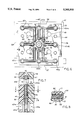
- FIG. 7 is a view in vertical section taken along line 7--7 of FIG. 6.
- FIG. 8 is a view in vertical section taken along line 8--8 of FIG. 7.
- FIG. 9 is a perspective view showing two of the distribution devices connected in a modular manner.
- FIG. 10 is a diagrammatic view showing an application of the distribution device.
- the distribution device generally 10 includes two identical body members 11 and 12 each having top walls 13, a tiered front wall 15, end walls 17 and 18 and back walls 19. Sandwiched between the body members 11 and 12 is a distribution member 16 in the form of a sheet like material.
- Body member 11 has nine tubular members as shown at 20a-i which are arranged in three tiered rows. Each of these tubular members have passages 22a-i which extend from the tiered front wall 15 to the back wall 19 as best seen in FIG. 4.
- Body member 12 is identical to body member 11 with the tubular members 24a-i having passages 26a-i which extend from the front wall 15 to the back wall 19 in a similar manner. This is best seen in FIG. 2. It will be appreciated that all of the tubular members 20a-i and tubular members 24a-i are in respective alignment when the body members are interconnected as are the respective passages 22a-i and 26a-i.
- Locating pegs 23 and 25 extend from the back walls 19 of body members 11 and 12 for reception in corresponding openings 28 in the opposing back walls 19. Additional and larger passageways 27 extend through body members 11 and 12 for the purpose of allowing fasteners to be placed therethrough to connect the body members 11 and 12 together in a permanent manner. It will also be seen that there is a U shaped recess 29 in body member 11 for purposes of securing it to a support surface. A similar recess is provided in body member 12. In addition bar members 30 extend laterally from one side of the body members 11 and 12 and a groove 31 extends from the opposing side. This is for the purpose of interconnecting several of the devices together as shown in FIG. 9 with the interconnection of body members 11' and 12' to body members 11 and 12.
- the distributor member 16 has a top edge 36, a bottom edge 37 and side edges 38 and 39. It also has opposing sides 35 and 41. Passages 40a-i correspond with passages 22a-i and 26a-i of respective body members 11 and 12 and are in alignment therewith when the distribution member 16 is sandwiched between them. They extend between the opposing sides 35 and 41. Openings 42 accommodate pegs 23 and passages 43 correspond to passageways 27.
- a plurality of smaller apertures 45-52 are spaced on side 35 of the distribution member 16 in a circular manner with respect to central passage 40e. In a manner similar to passages 40a-i, they also extend between sides 35 and 41.
- Linear channels 53 extend from apertures 45-52 and interconnect with circular channel 55.
- Grooves 57 and 58 extend between arcuate walls 61 and 62 and in turn connect circular channel 55 and central passage 40e.
- the passages 40a-i interconnect with the apertures 45-52 by means of the channels 70-77.
- Channels 70, 72, 74, and 76 are rectilinear whereas channels 71, 73, 75, and 77 are orthogonal.
- pressurized air which enters the central passage 22e of body member 11 will move through the linear channel 53 on side 35 of the distribution member 16 and then pass through a restriction 78 in aperture 45 and then along channel 70 on the opposing side to opposing passages 22b and 26b in respective body members 11 and 12.
- This flow pattern will be the same with respect to each linear channel 53 and the remaining respective apertures 46-52.
- air flow from each of the apertures 45-52 on side 41 of the distribution member 16 is to the respective passages 40a-i by means of the respective channels 70-77.
- the flow path of fluid through the body members 11 and 12 and distributor member 16 is for the pressurized air to be connected to the central tubular member 20e of body member 11 with flow through the passage 40e, the grooves 57 and 58, into the circular channel 55 and then into the linear channels 53.
- the air flows by means of the channels 70-77 to the opposing passages 22a-d, f-i and 26a-d, f-i.
- central passage 22e of body member 11 central passage 40e of distribution member 16 and 26e of body member 12
- these provide a through passage so that air can be interconnected through tubular member 24e at the opposing side and thus for interconnection with similar distribution devices or for other applications.
- air could be initially introduced into tubular member 24e rather than member 20e.
- the channels such as 70 have ribs 82 at opposing sides thereof on side 41 of distribution member 16.
- the bars 80 On the opposing side 35 there are the bars 80 which are a result of the molding of this member. However these bars 80 can be eliminated if desired.
- FIG. 9 there is illustrated a similar distribution device 10' interconnected with distribution device 10. This is effected by connecting the respect body sections 11 and 12 with similar body sections 10' and 11' by means of the bar members 30 and grooves 31.
- FIG. 10 represents a practical application of distribution device 10 for illustration purposes wherein it is used to control the heating or cooling of air.
- Pressurized air as from source 90 is interconnected to central member 20e by means of pressurized air line 91.
- the tubular member 20e is shown at the side of distribution device 10 rather than on the same side as the tubular members 20a-i shown in FIGS. 1 and 2.
- Air is distributed through distribution device 10 through tubular members such as 24a-c at one side to sensors 84, 85, 86 interconnected by means of lines 88.
- tubular members such as 20a-c to modular control units 93, 94, and 95 of the type described in U.S. Pat. No. 5,178,191.
- the modular control blocks 93-95 interconnected by the lines 96 operate in the manner fully described in the previously mentioned patent and provide the desired signal thereto.
- the preferred material for composing the body members 11 and 12 is a ridged molded thermoplastic available from General Electric Company as Prevex resin. However other suitable materials could be used such as die cast aluminum.
- Distribution member 16 is preferably composed of a Texin 355D plastic resin available from Miles Inc. Other materials such as rubber or flexible plastics could be substituted if desired.
- distribution device 10 An important feature of distribution device 10 is not only its ability to distribute fluid to a multiplicity of passages but that it also can reduce flow such as by means of restriction 78 in the apertures 45-52. Thus it is particularly suitable for use with a pneumatic sensor and a pneumatic control.
- a gasket could be placed on each side of the distribution member 16 and between it and the body members 11 and 12.
- the gaskets would, of course, have the same corresponding passages and channels to allow the passage of fluid.
- Apertures 45-52 are molded during the fabrication molding process. If desired, and to eliminate any problem with flash, these apertures could be laser drilled.
- fluid distribution device of this invention is useful in conjunction with controls for heating or cooling of air, it is adaptable to any control function where fluid input is required for various sensors and control units.
- tubular members 20a-i and 24a-i have been indicated with the respective passages, any number could be employed by increasing or decreasing the number of radially disposed apertures 45-52. These also could be positioned in different geometric configurations with respect to the central passage 40e. The same is true with respect to the respective passages 22a-i, 26a-i and tubular members 20a-i, 24a-i.
Abstract
A fluid distribution device which can direct the flow of a fluid from a common source to a plurality of outlet ports wherein a distribution plate is sandwiched between members which serve as inlet and outlet ports. In a preferred manner, there is a flow restrictor in the distribution plate which is provided by passages extending through the plate. The members are symmetrical in configuration with one of the members providing as inlet port and both members providing outlet ports. This results in cost reduction. The fluid distribution device is particularly suitable for use with pneumatic control systems.
Description
This invention relates to fluid distribution devices, and particularly, such devices which can reduce fluid flow and thus are particularly suited for use in conjunction with pneumatic control systems.
Fluid distributors employing two body members with a distribution plate therebetween are well known. One is shown in U.S. Pat. No. 4,537,217. The use of membranes in fluid distributors are also known. One is described in U.S. Pat. No. 5,176,359. In U.S. Pat. No. 3,991,786, a fluid distribution plate is described for use in conjunction with logic control valve devices.
While the prior art provides fluid distribution devices of various types and configurations, they do not afford a simplified device wherein opposing members of the devices are identical and an intermediate distribution plate can effect a predetermined flow restriction.
It is an advantage of the present invention to provide a fluid distribution device which has symmetrical components and thus reduces cost to manufacture.
It is another advantage of the present invention to provide a fluid distribution device of the foregoing type which can effect a determined flow rate.
It is yet another advantage of the present invention to provide a fluid distribution device of the foregoing type which is useful in conjunction with pneumatic control systems.
It is still another advantage of the present invention to provide a fluid distribution device of the foregoing type which can be connected in a modular manner.
The foregoing advantages are accomplished and the shortcomings of the prior art are overcome by the present device for distributing fluid from a single inlet to a multiplicity of outlets which includes a first member having a first side with at least one inlet port on the first side and a passage extending from the inlet port to a second side of the first member. There is a second member having a first side and a plurality of port passages extending between the first side and a second side of the second member. A third member is placed between the second sides of the first and second members with a passage in the third member communicating with the inlet port of the first member. A plurality of passages in the third member communicate with the passage in communication with the inlet port at one side with the plurality of passages extending through the third member from the one side to another side and connected to channel portions extending over the other side, the plurality of passages communicating with the port passages of the second member.
In one preferred embodiment, the plurality of passages extending through the third member include a flow restrictor therein.
In one aspect, the third member is composed of a sheet like material and the first and second members include tubular projections arranged in tiered rows and provide extensions of the port passages.
In another preferred embodiment, the passage in the third member communicating with the inlet port has a circular portion with radiating portions extending therefrom.
In still another preferred embodiment, the fluid distribution device can be connected to an additional device in a modular manner.
In yet another preferred embodiment, the port passages of the second member are adapted to be connected to a sensing device and some of the port passages of the first member are adapted to be connected to a control device.
FIG. 1 is a top perspective view showing the fluid distribution device of this invention.
FIG. 2 is an assembly view of the device shown in FIG. 1.
FIG. 3 is a view in side elevation showing one of the body members composing the distribution device of FIG. 1.
FIG. 4 is a view similar to FIG. 3 except showing a rear view of the body member.
FIG. 5 is an enlarged view in side elevation showing a distribution member for sandwiching between the body members.
FIG. 6 is a view similar to FIG. 5 except being a rear view of the distribution member.
FIG. 7 is a view in vertical section taken along line 7--7 of FIG. 6.
FIG. 8 is a view in vertical section taken along line 8--8 of FIG. 7.
FIG. 9 is a perspective view showing two of the distribution devices connected in a modular manner.
FIG. 10 is a diagrammatic view showing an application of the distribution device.
Referring to FIGS. 1-4, the distribution device generally 10 includes two identical body members 11 and 12 each having top walls 13, a tiered front wall 15, end walls 17 and 18 and back walls 19. Sandwiched between the body members 11 and 12 is a distribution member 16 in the form of a sheet like material.
Locating pegs 23 and 25 extend from the back walls 19 of body members 11 and 12 for reception in corresponding openings 28 in the opposing back walls 19. Additional and larger passageways 27 extend through body members 11 and 12 for the purpose of allowing fasteners to be placed therethrough to connect the body members 11 and 12 together in a permanent manner. It will also be seen that there is a U shaped recess 29 in body member 11 for purposes of securing it to a support surface. A similar recess is provided in body member 12. In addition bar members 30 extend laterally from one side of the body members 11 and 12 and a groove 31 extends from the opposing side. This is for the purpose of interconnecting several of the devices together as shown in FIG. 9 with the interconnection of body members 11' and 12' to body members 11 and 12.
Referring specifically to FIGS. 2, 5 and 6, the distributor member 16 has a top edge 36, a bottom edge 37 and side edges 38 and 39. It also has opposing sides 35 and 41. Passages 40a-i correspond with passages 22a-i and 26a-i of respective body members 11 and 12 and are in alignment therewith when the distribution member 16 is sandwiched between them. They extend between the opposing sides 35 and 41. Openings 42 accommodate pegs 23 and passages 43 correspond to passageways 27.
Referring specifically to FIG. 5, it is seen that a plurality of smaller apertures 45-52 are spaced on side 35 of the distribution member 16 in a circular manner with respect to central passage 40e. In a manner similar to passages 40a-i, they also extend between sides 35 and 41. Linear channels 53 extend from apertures 45-52 and interconnect with circular channel 55. Grooves 57 and 58 extend between arcuate walls 61 and 62 and in turn connect circular channel 55 and central passage 40e. Looking at the other side 41 of distribution member 16 in FIG. 6 it is seen that the passages 40a-i interconnect with the apertures 45-52 by means of the channels 70-77. Channels 70, 72, 74, and 76 are rectilinear whereas channels 71, 73, 75, and 77 are orthogonal.
Referring specifically to FIG. 7, pressurized air which enters the central passage 22e of body member 11 will move through the linear channel 53 on side 35 of the distribution member 16 and then pass through a restriction 78 in aperture 45 and then along channel 70 on the opposing side to opposing passages 22b and 26b in respective body members 11 and 12. This flow pattern will be the same with respect to each linear channel 53 and the remaining respective apertures 46-52. As seen in FIG. 6 and referred to earlier, air flow from each of the apertures 45-52 on side 41 of the distribution member 16 is to the respective passages 40a-i by means of the respective channels 70-77.
Accordingly, the flow path of fluid through the body members 11 and 12 and distributor member 16 is for the pressurized air to be connected to the central tubular member 20e of body member 11 with flow through the passage 40e, the grooves 57 and 58, into the circular channel 55 and then into the linear channels 53. After passing through the restriction 78 of each aperture 45-52 the air flows by means of the channels 70-77 to the opposing passages 22a-d, f-i and 26a-d, f-i. With respect to central passage 22e of body member 11, central passage 40e of distribution member 16 and 26e of body member 12, these provide a through passage so that air can be interconnected through tubular member 24e at the opposing side and thus for interconnection with similar distribution devices or for other applications. Alternatively, air could be initially introduced into tubular member 24e rather than member 20e.
Referring to FIG. 8, it is seen that the channels such as 70 have ribs 82 at opposing sides thereof on side 41 of distribution member 16. On the opposing side 35 there are the bars 80 which are a result of the molding of this member. However these bars 80 can be eliminated if desired.
Referring to FIG. 9, there is illustrated a similar distribution device 10' interconnected with distribution device 10. This is effected by connecting the respect body sections 11 and 12 with similar body sections 10' and 11' by means of the bar members 30 and grooves 31.
FIG. 10 represents a practical application of distribution device 10 for illustration purposes wherein it is used to control the heating or cooling of air. Pressurized air as from source 90 is interconnected to central member 20e by means of pressurized air line 91. In this instance and for illustration purposes the tubular member 20e is shown at the side of distribution device 10 rather than on the same side as the tubular members 20a-i shown in FIGS. 1 and 2. Air is distributed through distribution device 10 through tubular members such as 24a-c at one side to sensors 84, 85, 86 interconnected by means of lines 88. At the opposite side connection is made through tubular members such as 20a-c to modular control units 93, 94, and 95 of the type described in U.S. Pat. No. 5,178,191. The modular control blocks 93-95 interconnected by the lines 96 operate in the manner fully described in the previously mentioned patent and provide the desired signal thereto.
The preferred material for composing the body members 11 and 12 is a ridged molded thermoplastic available from General Electric Company as Prevex resin. However other suitable materials could be used such as die cast aluminum. Distribution member 16 is preferably composed of a Texin 355D plastic resin available from Miles Inc. Other materials such as rubber or flexible plastics could be substituted if desired.
An important feature of distribution device 10 is not only its ability to distribute fluid to a multiplicity of passages but that it also can reduce flow such as by means of restriction 78 in the apertures 45-52. Thus it is particularly suitable for use with a pneumatic sensor and a pneumatic control.
In order to assure proper sealing between the various passages and channels in the body members 11 and 12 and the distribution member 16, a gasket could be placed on each side of the distribution member 16 and between it and the body members 11 and 12. The gaskets would, of course, have the same corresponding passages and channels to allow the passage of fluid. Apertures 45-52 are molded during the fabrication molding process. If desired, and to eliminate any problem with flash, these apertures could be laser drilled.
It will thus be seen that from the previously described invention there is now provided a fluid distribution device which by means of two body sections and a distribution member can distribute air to various apertures as well as provide a reduced flow rate. Substantial cost savings is thereby effected over the prior art which utilizes separate supply lines for a control and sensor and connection through a manifold.
While the fluid distribution device of this invention is useful in conjunction with controls for heating or cooling of air, it is adaptable to any control function where fluid input is required for various sensors and control units.
It will be apparent to those skilled in the art that a number of variations can be made of the preferred embodiments without departing from the spirit of the invention. For example, while a designated number of tubular members 20a-i and 24a-i have been indicated with the respective passages, any number could be employed by increasing or decreasing the number of radially disposed apertures 45-52. These also could be positioned in different geometric configurations with respect to the central passage 40e. The same is true with respect to the respective passages 22a-i, 26a-i and tubular members 20a-i, 24a-i.
Claims (11)
1. A device for distributing fluid from a single inlet to a multiplicity of outlets comprising:
a first member having a first side with at least one inlet port on the first side;
a passage extending from the inlet port to a second side of the first member;
a second member having a first side;
a plurality of port passages extending between the first side and a second side of the second member;
a third member placed between the second sides of the first and second members;
a passage in the third member communicating with the inlet port of the first member;
a plurality of passages in the third member communicating with the passage in communication with the inlet port at one side, the plurality of passages extending through the third member from the one side to another side and connected to channel portions extending over the other side of the third member, the plurality of passages communicating with the port passages of the second member by means of the channel portions.
2. The device of claim 1 wherein the plurality of passages extending through the third member include a flow restrictor.
3. The device of claim 2 wherein the third member is composed of a sheet like material.
4. A device for distributing fluid from a single inlet to a multiplicity of outlets comprising:
a first member having a first side with at least one inlet port on the first side;
a passage extending from the inlet port to a second side of the first member.;
a second member having a first side;
a plurality of port passages extending between the first side and a second side of the second member;
a third member placed between the second sides of the first and second members;
a passage in the third member communicating with the inlet port of the first member;
a plurality of passages in the third member communicating with the passage in communication with the inlet port at one side, the plurality of passages extending through the third member from the one side to another side and connected to channel portions extending over the other side member, the plurality of passages communicating with the port passages of the second member, the third member having a plurality of additional passages extending through the third member from one side to the other side and the first member has a plurality of port members extending from the one side and in communication with the additional passages and the port passages of the second member.
5. The device of claim 4 wherein the port members of the first and second members include tubular projections arranged in tiered rows.
6. The device of claim 1 further including connecting members disposed on the first and second members for connection to additional body members.
7. The device of claim 1 further including slots disposed in the first and second members for attachment to a supporting surface.
8. The device of claim 4 wherein the port passages of the second member are adapted to be connected to a sensing device and the port passages of the first members are adapted to be connected to a control device.
9. The device of claim 1 wherein the passage in the third member communicating with the inlet port has a circular portion connected with radiating channel portions extending therefrom.
10. The device of claim 9 wherein some of the channel portions extending over the other side of the third member and communicating with the port passages of the second member are rectilinear and others are orthogonal.
11. The device of claim 1 wherein the first and second members are in certain instances essentially identical.
Priority Applications (1)
| Application Number | Priority Date | Filing Date | Title |
|---|---|---|---|
| US08/139,244 US5341841A (en) | 1993-10-19 | 1993-10-19 | Fluid distribution device |
Applications Claiming Priority (1)
| Application Number | Priority Date | Filing Date | Title |
|---|---|---|---|
| US08/139,244 US5341841A (en) | 1993-10-19 | 1993-10-19 | Fluid distribution device |
Publications (1)
| Publication Number | Publication Date |
|---|---|
| US5341841A true US5341841A (en) | 1994-08-30 |
Family
ID=22485742
Family Applications (1)
| Application Number | Title | Priority Date | Filing Date |
|---|---|---|---|
| US08/139,244 Expired - Fee Related US5341841A (en) | 1993-10-19 | 1993-10-19 | Fluid distribution device |
Country Status (1)
| Country | Link |
|---|---|
| US (1) | US5341841A (en) |
Cited By (21)
| Publication number | Priority date | Publication date | Assignee | Title |
|---|---|---|---|---|
| US5808179A (en) * | 1995-09-29 | 1998-09-15 | Rosemount Analytical Inc. | Modular gas chromatograph |
| US6241046B1 (en) * | 1997-09-17 | 2001-06-05 | Junichi Yokoi | Mechanical arrangement for feeding fluid at a minute flow rate |
| US6289928B1 (en) * | 1998-12-04 | 2001-09-18 | Basf Corporation | Apparatus and method for direct injection of additives into a polymer melt stream |
| WO2003067095A1 (en) * | 2002-02-02 | 2003-08-14 | Robert Bosch Gmbh | Multiple valve arrangement for flowing media |
| US20050121468A1 (en) * | 2001-10-29 | 2005-06-09 | Nordson Corporation | Hot melt adhesive system having centralized manifold and zone heating capability |
| US20070295401A1 (en) * | 2004-09-17 | 2007-12-27 | Ckd Coroporation | Flow Path Block |
| US8397586B2 (en) | 2010-03-22 | 2013-03-19 | Honeywell International Inc. | Flow sensor assembly with porous insert |
| US8485031B2 (en) | 2010-03-22 | 2013-07-16 | Honeywell International Inc. | Sensor assembly with hydrophobic filter |
| US20140000654A1 (en) * | 2012-06-27 | 2014-01-02 | Raytheon Company | Receptacle cleaning systems and methods for the same |
| US8656772B2 (en) | 2010-03-22 | 2014-02-25 | Honeywell International Inc. | Flow sensor with pressure output signal |
| US8695417B2 (en) | 2011-01-31 | 2014-04-15 | Honeywell International Inc. | Flow sensor with enhanced flow range capability |
| US8756990B2 (en) | 2010-04-09 | 2014-06-24 | Honeywell International Inc. | Molded flow restrictor |
| US9003877B2 (en) | 2010-06-15 | 2015-04-14 | Honeywell International Inc. | Flow sensor assembly |
| US9052217B2 (en) | 2012-11-09 | 2015-06-09 | Honeywell International Inc. | Variable scale sensor |
| US9091577B2 (en) | 2011-01-31 | 2015-07-28 | Honeywell International Inc. | Flow sensor assembly with integral bypass channel |
| US20170328383A1 (en) * | 2015-06-09 | 2017-11-16 | Festo Ag & Co. Kg | Valve Arrangement |
| US9952079B2 (en) | 2015-07-15 | 2018-04-24 | Honeywell International Inc. | Flow sensor |
| US10337534B2 (en) * | 2015-02-25 | 2019-07-02 | Knorr-Bremse Systeme Fuer Nutzfahrzeuge Gmbh | Pressure medium device comprising fluidic connections which are variable on the basis of molded seals |
| US20190382216A1 (en) * | 2015-09-22 | 2019-12-19 | Deere & Company | Agricultural vehicle pneumatic distribution system |
| US10794519B2 (en) | 2016-01-15 | 2020-10-06 | Lam Research Corporation | Additively manufactured gas distribution manifold |
| US10914003B2 (en) | 2014-10-17 | 2021-02-09 | Lam Research Corporation | Monolithic gas distribution manifold and various construction techniques and use cases therefor |
Citations (14)
| Publication number | Priority date | Publication date | Assignee | Title |
|---|---|---|---|---|
| US3001544A (en) * | 1960-07-05 | 1961-09-26 | Allis Chalmers Mfg Co | Moisture distributor |
| US3391703A (en) * | 1964-08-06 | 1968-07-09 | Applied Controls Ltd | Fluid connector units |
| US3658088A (en) * | 1970-06-17 | 1972-04-25 | Ibm | Packaging system for pneumatic logic |
| US3760844A (en) * | 1971-07-19 | 1973-09-25 | Westinghouse Air Brake Co | Circuit module for fluid distribution |
| US3795259A (en) * | 1971-07-07 | 1974-03-05 | Stal Refrigeration Ab | Device for evenly mixing and distributing a gas and liquid mixture |
| US3814126A (en) * | 1971-09-15 | 1974-06-04 | Samson Apparatebau Ag | Fluid conducting system |
| US3934605A (en) * | 1973-07-03 | 1976-01-27 | Societe Legris France S.A. | Modular distributor box for fluids |
| US3991786A (en) * | 1975-09-22 | 1976-11-16 | American Standard, Inc. | Fluid circuit plate for a circuit module for fluid distribution |
| US4299553A (en) * | 1979-12-14 | 1981-11-10 | The Continental Group, Inc. | Hot runner manifold flow distributor plug |
| US4333629A (en) * | 1980-03-11 | 1982-06-08 | Pepsico, Inc. | Floating manifold for multi-cavity injection mold |
| US4535821A (en) * | 1982-05-19 | 1985-08-20 | John Anderson | Three way valve |
| US4537217A (en) * | 1982-12-09 | 1985-08-27 | Research Triangle Institute | Fluid distributor |
| US5176359A (en) * | 1991-05-20 | 1993-01-05 | Photovac International, Inc. | Fluid control valve arrangement |
| US5178191A (en) * | 1990-09-05 | 1993-01-12 | Newmatic Controls Inc. | Modular pneumatic control systems |
-
1993
- 1993-10-19 US US08/139,244 patent/US5341841A/en not_active Expired - Fee Related
Patent Citations (14)
| Publication number | Priority date | Publication date | Assignee | Title |
|---|---|---|---|---|
| US3001544A (en) * | 1960-07-05 | 1961-09-26 | Allis Chalmers Mfg Co | Moisture distributor |
| US3391703A (en) * | 1964-08-06 | 1968-07-09 | Applied Controls Ltd | Fluid connector units |
| US3658088A (en) * | 1970-06-17 | 1972-04-25 | Ibm | Packaging system for pneumatic logic |
| US3795259A (en) * | 1971-07-07 | 1974-03-05 | Stal Refrigeration Ab | Device for evenly mixing and distributing a gas and liquid mixture |
| US3760844A (en) * | 1971-07-19 | 1973-09-25 | Westinghouse Air Brake Co | Circuit module for fluid distribution |
| US3814126A (en) * | 1971-09-15 | 1974-06-04 | Samson Apparatebau Ag | Fluid conducting system |
| US3934605A (en) * | 1973-07-03 | 1976-01-27 | Societe Legris France S.A. | Modular distributor box for fluids |
| US3991786A (en) * | 1975-09-22 | 1976-11-16 | American Standard, Inc. | Fluid circuit plate for a circuit module for fluid distribution |
| US4299553A (en) * | 1979-12-14 | 1981-11-10 | The Continental Group, Inc. | Hot runner manifold flow distributor plug |
| US4333629A (en) * | 1980-03-11 | 1982-06-08 | Pepsico, Inc. | Floating manifold for multi-cavity injection mold |
| US4535821A (en) * | 1982-05-19 | 1985-08-20 | John Anderson | Three way valve |
| US4537217A (en) * | 1982-12-09 | 1985-08-27 | Research Triangle Institute | Fluid distributor |
| US5178191A (en) * | 1990-09-05 | 1993-01-12 | Newmatic Controls Inc. | Modular pneumatic control systems |
| US5176359A (en) * | 1991-05-20 | 1993-01-05 | Photovac International, Inc. | Fluid control valve arrangement |
Cited By (30)
| Publication number | Priority date | Publication date | Assignee | Title |
|---|---|---|---|---|
| US6029499A (en) * | 1995-09-29 | 2000-02-29 | Rosemount Analytical Inc. | Modular gas chromatograph |
| US5808179A (en) * | 1995-09-29 | 1998-09-15 | Rosemount Analytical Inc. | Modular gas chromatograph |
| US6241046B1 (en) * | 1997-09-17 | 2001-06-05 | Junichi Yokoi | Mechanical arrangement for feeding fluid at a minute flow rate |
| US6289928B1 (en) * | 1998-12-04 | 2001-09-18 | Basf Corporation | Apparatus and method for direct injection of additives into a polymer melt stream |
| US20050121468A1 (en) * | 2001-10-29 | 2005-06-09 | Nordson Corporation | Hot melt adhesive system having centralized manifold and zone heating capability |
| US7694854B2 (en) * | 2001-10-29 | 2010-04-13 | Nordson Corporation | Hot melt adhesive system having centralized manifold and zone heating capability |
| WO2003067095A1 (en) * | 2002-02-02 | 2003-08-14 | Robert Bosch Gmbh | Multiple valve arrangement for flowing media |
| US20040089837A1 (en) * | 2002-02-02 | 2004-05-13 | Bertram Bauer | Multple valve arrangement for flowing media |
| US20070295401A1 (en) * | 2004-09-17 | 2007-12-27 | Ckd Coroporation | Flow Path Block |
| US8656772B2 (en) | 2010-03-22 | 2014-02-25 | Honeywell International Inc. | Flow sensor with pressure output signal |
| US8397586B2 (en) | 2010-03-22 | 2013-03-19 | Honeywell International Inc. | Flow sensor assembly with porous insert |
| US8485031B2 (en) | 2010-03-22 | 2013-07-16 | Honeywell International Inc. | Sensor assembly with hydrophobic filter |
| US8756990B2 (en) | 2010-04-09 | 2014-06-24 | Honeywell International Inc. | Molded flow restrictor |
| US9003877B2 (en) | 2010-06-15 | 2015-04-14 | Honeywell International Inc. | Flow sensor assembly |
| US8695417B2 (en) | 2011-01-31 | 2014-04-15 | Honeywell International Inc. | Flow sensor with enhanced flow range capability |
| US9091577B2 (en) | 2011-01-31 | 2015-07-28 | Honeywell International Inc. | Flow sensor assembly with integral bypass channel |
| US20140000654A1 (en) * | 2012-06-27 | 2014-01-02 | Raytheon Company | Receptacle cleaning systems and methods for the same |
| US9550218B2 (en) * | 2012-06-27 | 2017-01-24 | Raytheon Company | Receptacle cleaning systems and methods for the same |
| US9052217B2 (en) | 2012-11-09 | 2015-06-09 | Honeywell International Inc. | Variable scale sensor |
| US10914003B2 (en) | 2014-10-17 | 2021-02-09 | Lam Research Corporation | Monolithic gas distribution manifold and various construction techniques and use cases therefor |
| US10337534B2 (en) * | 2015-02-25 | 2019-07-02 | Knorr-Bremse Systeme Fuer Nutzfahrzeuge Gmbh | Pressure medium device comprising fluidic connections which are variable on the basis of molded seals |
| US10605274B2 (en) * | 2015-06-09 | 2020-03-31 | Festo Ag & Co. Kg | Valve arrangement |
| US20170328383A1 (en) * | 2015-06-09 | 2017-11-16 | Festo Ag & Co. Kg | Valve Arrangement |
| US9952079B2 (en) | 2015-07-15 | 2018-04-24 | Honeywell International Inc. | Flow sensor |
| US20190382216A1 (en) * | 2015-09-22 | 2019-12-19 | Deere & Company | Agricultural vehicle pneumatic distribution system |
| US20190382217A1 (en) * | 2015-09-22 | 2019-12-19 | Deere & Company | Agricultural vehicle pneumatic distribution system |
| US10934106B2 (en) * | 2015-09-22 | 2021-03-02 | Deere & Company | Agricultural vehicle pneumatic distribution system |
| US10941008B2 (en) * | 2015-09-22 | 2021-03-09 | Deere & Company | Agricultural vehicle pneumatic distribution system |
| US11745959B2 (en) | 2015-09-22 | 2023-09-05 | Deere & Company | Agricultural vehicle pneumatic distribution system |
| US10794519B2 (en) | 2016-01-15 | 2020-10-06 | Lam Research Corporation | Additively manufactured gas distribution manifold |
Similar Documents
| Publication | Publication Date | Title |
|---|---|---|
| US5341841A (en) | Fluid distribution device | |
| US5080166A (en) | Plate-shaped heating element, in particular for floor heating | |
| EP1022936B1 (en) | An improved irrigation emitter unit | |
| EP0195450B1 (en) | Stacked motionless mixer | |
| EP1316368B1 (en) | Hot melt adhesive flow control system | |
| US4696625A (en) | Ejector and method of fabrication | |
| US4911628A (en) | Triwall siding apparatus | |
| EP0672462A2 (en) | Fluid applicator | |
| JP4813694B2 (en) | Glue output distribution nozzle assembly | |
| ATE127909T1 (en) | HEAT EXCHANGER WITH MULTI-LAYER PLATE ELEMENTS. | |
| CA2183478A1 (en) | Digital gas metering system using tri-stable and bi-stable solenoids | |
| JPS6227977B2 (en) | ||
| CA2225035A1 (en) | Electrodialysis apparatus | |
| IL109269A (en) | Heat exchanger | |
| EP0853972A3 (en) | Electrodeionization apparatus and module | |
| US4733685A (en) | Cyclic flow distributor | |
| KR20060120564A (en) | Apparatus for depositing fluid material onto a substrate | |
| ES8506397A1 (en) | Heat exchanger of plastics material. | |
| US20040089837A1 (en) | Multple valve arrangement for flowing media | |
| JPH09257386A (en) | Distributor and heat exchanger equipped with it | |
| IL48258A (en) | Manifold for injection molding machine | |
| US4109680A (en) | Plate type fluid distributing device | |
| US4130137A (en) | Fluid distribution system | |
| US7021336B2 (en) | Even-flow septic tee arrangement | |
| US5480004A (en) | Crossport and singling manifold for a series progressive divider valve |
Legal Events
| Date | Code | Title | Description |
|---|---|---|---|
| AS | Assignment |
Owner name: ACUTE IDEAS, INC., WISCONSIN Free format text: ASSIGNMENT OF ASSIGNORS INTEREST;ASSIGNOR:SCHAEFER, JOSEPH H.;REEL/FRAME:006745/0812 Effective date: 19931014 |
|
| REMI | Maintenance fee reminder mailed | ||
| LAPS | Lapse for failure to pay maintenance fees | ||
| FP | Lapsed due to failure to pay maintenance fee |
Effective date: 19980830 |
|
| STCH | Information on status: patent discontinuation |
Free format text: PATENT EXPIRED DUE TO NONPAYMENT OF MAINTENANCE FEES UNDER 37 CFR 1.362 |