EP3146739B1 - Periodic and aperiodic channel state information (csi) reporting for mimo - Google Patents
Periodic and aperiodic channel state information (csi) reporting for mimo Download PDFInfo
- Publication number
- EP3146739B1 EP3146739B1 EP14892803.9A EP14892803A EP3146739B1 EP 3146739 B1 EP3146739 B1 EP 3146739B1 EP 14892803 A EP14892803 A EP 14892803A EP 3146739 B1 EP3146739 B1 EP 3146739B1
- Authority
- EP
- European Patent Office
- Prior art keywords
- antenna ports
- csi
- reporting
- periodic
- information
- Prior art date
- Legal status (The legal status is an assumption and is not a legal conclusion. Google has not performed a legal analysis and makes no representation as to the accuracy of the status listed.)
- Active
Links
- 230000000737 periodic effect Effects 0.000 title claims description 60
- 238000000034 method Methods 0.000 claims description 40
- 238000004891 communication Methods 0.000 claims description 36
- 238000005259 measurement Methods 0.000 claims description 16
- 239000011159 matrix material Substances 0.000 claims description 9
- 230000011664 signaling Effects 0.000 claims description 3
- 238000004590 computer program Methods 0.000 claims description 2
- 230000005540 biological transmission Effects 0.000 description 15
- 238000005516 engineering process Methods 0.000 description 10
- 230000008569 process Effects 0.000 description 9
- 239000013598 vector Substances 0.000 description 8
- 230000015654 memory Effects 0.000 description 7
- 230000006870 function Effects 0.000 description 5
- 239000002131 composite material Substances 0.000 description 4
- 238000010586 diagram Methods 0.000 description 4
- 125000004122 cyclic group Chemical group 0.000 description 3
- 230000001419 dependent effect Effects 0.000 description 3
- 238000013461 design Methods 0.000 description 3
- 230000007774 longterm Effects 0.000 description 3
- 230000003287 optical effect Effects 0.000 description 3
- 230000009467 reduction Effects 0.000 description 3
- 230000007480 spreading Effects 0.000 description 3
- 239000000835 fiber Substances 0.000 description 2
- 230000008520 organization Effects 0.000 description 2
- 239000002245 particle Substances 0.000 description 2
- 238000012545 processing Methods 0.000 description 2
- 230000002441 reversible effect Effects 0.000 description 2
- 238000003491 array Methods 0.000 description 1
- 230000015572 biosynthetic process Effects 0.000 description 1
- 230000015556 catabolic process Effects 0.000 description 1
- 230000001413 cellular effect Effects 0.000 description 1
- 230000008859 change Effects 0.000 description 1
- 230000000295 complement effect Effects 0.000 description 1
- 238000006731 degradation reaction Methods 0.000 description 1
- 238000001514 detection method Methods 0.000 description 1
- 238000012423 maintenance Methods 0.000 description 1
- 238000013507 mapping Methods 0.000 description 1
- 230000007246 mechanism Effects 0.000 description 1
- 238000010295 mobile communication Methods 0.000 description 1
- 238000012986 modification Methods 0.000 description 1
- 230000004048 modification Effects 0.000 description 1
- 230000004044 response Effects 0.000 description 1
- 230000001360 synchronised effect Effects 0.000 description 1
- 238000012549 training Methods 0.000 description 1
- 238000012546 transfer Methods 0.000 description 1
- 238000011144 upstream manufacturing Methods 0.000 description 1
Images


Classifications
-
- H—ELECTRICITY
- H04—ELECTRIC COMMUNICATION TECHNIQUE
- H04W—WIRELESS COMMUNICATION NETWORKS
- H04W24/00—Supervisory, monitoring or testing arrangements
- H04W24/10—Scheduling measurement reports ; Arrangements for measurement reports
-
- H—ELECTRICITY
- H04—ELECTRIC COMMUNICATION TECHNIQUE
- H04B—TRANSMISSION
- H04B7/00—Radio transmission systems, i.e. using radiation field
- H04B7/02—Diversity systems; Multi-antenna system, i.e. transmission or reception using multiple antennas
- H04B7/04—Diversity systems; Multi-antenna system, i.e. transmission or reception using multiple antennas using two or more spaced independent antennas
- H04B7/0413—MIMO systems
- H04B7/0456—Selection of precoding matrices or codebooks, e.g. using matrices antenna weighting
- H04B7/046—Selection of precoding matrices or codebooks, e.g. using matrices antenna weighting taking physical layer constraints into account
- H04B7/0469—Selection of precoding matrices or codebooks, e.g. using matrices antenna weighting taking physical layer constraints into account taking special antenna structures, e.g. cross polarized antennas into account
-
- H—ELECTRICITY
- H04—ELECTRIC COMMUNICATION TECHNIQUE
- H04B—TRANSMISSION
- H04B7/00—Radio transmission systems, i.e. using radiation field
- H04B7/02—Diversity systems; Multi-antenna system, i.e. transmission or reception using multiple antennas
- H04B7/04—Diversity systems; Multi-antenna system, i.e. transmission or reception using multiple antennas using two or more spaced independent antennas
- H04B7/0413—MIMO systems
- H04B7/0456—Selection of precoding matrices or codebooks, e.g. using matrices antenna weighting
- H04B7/0478—Special codebook structures directed to feedback optimisation
-
- H—ELECTRICITY
- H04—ELECTRIC COMMUNICATION TECHNIQUE
- H04B—TRANSMISSION
- H04B7/00—Radio transmission systems, i.e. using radiation field
- H04B7/02—Diversity systems; Multi-antenna system, i.e. transmission or reception using multiple antennas
- H04B7/04—Diversity systems; Multi-antenna system, i.e. transmission or reception using multiple antennas using two or more spaced independent antennas
- H04B7/06—Diversity systems; Multi-antenna system, i.e. transmission or reception using multiple antennas using two or more spaced independent antennas at the transmitting station
- H04B7/0613—Diversity systems; Multi-antenna system, i.e. transmission or reception using multiple antennas using two or more spaced independent antennas at the transmitting station using simultaneous transmission
- H04B7/0615—Diversity systems; Multi-antenna system, i.e. transmission or reception using multiple antennas using two or more spaced independent antennas at the transmitting station using simultaneous transmission of weighted versions of same signal
- H04B7/0619—Diversity systems; Multi-antenna system, i.e. transmission or reception using multiple antennas using two or more spaced independent antennas at the transmitting station using simultaneous transmission of weighted versions of same signal using feedback from receiving side
- H04B7/0621—Feedback content
- H04B7/0626—Channel coefficients, e.g. channel state information [CSI]
-
- H—ELECTRICITY
- H04—ELECTRIC COMMUNICATION TECHNIQUE
- H04B—TRANSMISSION
- H04B7/00—Radio transmission systems, i.e. using radiation field
- H04B7/02—Diversity systems; Multi-antenna system, i.e. transmission or reception using multiple antennas
- H04B7/04—Diversity systems; Multi-antenna system, i.e. transmission or reception using multiple antennas using two or more spaced independent antennas
- H04B7/06—Diversity systems; Multi-antenna system, i.e. transmission or reception using multiple antennas using two or more spaced independent antennas at the transmitting station
- H04B7/0613—Diversity systems; Multi-antenna system, i.e. transmission or reception using multiple antennas using two or more spaced independent antennas at the transmitting station using simultaneous transmission
- H04B7/0615—Diversity systems; Multi-antenna system, i.e. transmission or reception using multiple antennas using two or more spaced independent antennas at the transmitting station using simultaneous transmission of weighted versions of same signal
- H04B7/0619—Diversity systems; Multi-antenna system, i.e. transmission or reception using multiple antennas using two or more spaced independent antennas at the transmitting station using simultaneous transmission of weighted versions of same signal using feedback from receiving side
- H04B7/0621—Feedback content
- H04B7/063—Parameters other than those covered in groups H04B7/0623 - H04B7/0634, e.g. channel matrix rank or transmit mode selection
-
- H—ELECTRICITY
- H04—ELECTRIC COMMUNICATION TECHNIQUE
- H04B—TRANSMISSION
- H04B7/00—Radio transmission systems, i.e. using radiation field
- H04B7/02—Diversity systems; Multi-antenna system, i.e. transmission or reception using multiple antennas
- H04B7/04—Diversity systems; Multi-antenna system, i.e. transmission or reception using multiple antennas using two or more spaced independent antennas
- H04B7/06—Diversity systems; Multi-antenna system, i.e. transmission or reception using multiple antennas using two or more spaced independent antennas at the transmitting station
- H04B7/0613—Diversity systems; Multi-antenna system, i.e. transmission or reception using multiple antennas using two or more spaced independent antennas at the transmitting station using simultaneous transmission
- H04B7/0615—Diversity systems; Multi-antenna system, i.e. transmission or reception using multiple antennas using two or more spaced independent antennas at the transmitting station using simultaneous transmission of weighted versions of same signal
- H04B7/0619—Diversity systems; Multi-antenna system, i.e. transmission or reception using multiple antennas using two or more spaced independent antennas at the transmitting station using simultaneous transmission of weighted versions of same signal using feedback from receiving side
- H04B7/0636—Feedback format
- H04B7/0639—Using selective indices, e.g. of a codebook, e.g. pre-distortion matrix index [PMI] or for beam selection
-
- H—ELECTRICITY
- H04—ELECTRIC COMMUNICATION TECHNIQUE
- H04B—TRANSMISSION
- H04B7/00—Radio transmission systems, i.e. using radiation field
- H04B7/02—Diversity systems; Multi-antenna system, i.e. transmission or reception using multiple antennas
- H04B7/04—Diversity systems; Multi-antenna system, i.e. transmission or reception using multiple antennas using two or more spaced independent antennas
- H04B7/06—Diversity systems; Multi-antenna system, i.e. transmission or reception using multiple antennas using two or more spaced independent antennas at the transmitting station
- H04B7/0613—Diversity systems; Multi-antenna system, i.e. transmission or reception using multiple antennas using two or more spaced independent antennas at the transmitting station using simultaneous transmission
- H04B7/0615—Diversity systems; Multi-antenna system, i.e. transmission or reception using multiple antennas using two or more spaced independent antennas at the transmitting station using simultaneous transmission of weighted versions of same signal
- H04B7/0619—Diversity systems; Multi-antenna system, i.e. transmission or reception using multiple antennas using two or more spaced independent antennas at the transmitting station using simultaneous transmission of weighted versions of same signal using feedback from receiving side
- H04B7/0636—Feedback format
- H04B7/0645—Variable feedback
- H04B7/0647—Variable feedback rate
-
- H—ELECTRICITY
- H04—ELECTRIC COMMUNICATION TECHNIQUE
- H04B—TRANSMISSION
- H04B7/00—Radio transmission systems, i.e. using radiation field
- H04B7/02—Diversity systems; Multi-antenna system, i.e. transmission or reception using multiple antennas
- H04B7/04—Diversity systems; Multi-antenna system, i.e. transmission or reception using multiple antennas using two or more spaced independent antennas
- H04B7/06—Diversity systems; Multi-antenna system, i.e. transmission or reception using multiple antennas using two or more spaced independent antennas at the transmitting station
- H04B7/0686—Hybrid systems, i.e. switching and simultaneous transmission
- H04B7/0691—Hybrid systems, i.e. switching and simultaneous transmission using subgroups of transmit antennas
-
- H—ELECTRICITY
- H04—ELECTRIC COMMUNICATION TECHNIQUE
- H04L—TRANSMISSION OF DIGITAL INFORMATION, e.g. TELEGRAPHIC COMMUNICATION
- H04L1/00—Arrangements for detecting or preventing errors in the information received
- H04L1/0001—Systems modifying transmission characteristics according to link quality, e.g. power backoff
- H04L1/0023—Systems modifying transmission characteristics according to link quality, e.g. power backoff characterised by the signalling
- H04L1/0026—Transmission of channel quality indication
-
- H—ELECTRICITY
- H04—ELECTRIC COMMUNICATION TECHNIQUE
- H04L—TRANSMISSION OF DIGITAL INFORMATION, e.g. TELEGRAPHIC COMMUNICATION
- H04L5/00—Arrangements affording multiple use of the transmission path
- H04L5/0001—Arrangements for dividing the transmission path
- H04L5/0014—Three-dimensional division
- H04L5/0023—Time-frequency-space
-
- H—ELECTRICITY
- H04—ELECTRIC COMMUNICATION TECHNIQUE
- H04L—TRANSMISSION OF DIGITAL INFORMATION, e.g. TELEGRAPHIC COMMUNICATION
- H04L5/00—Arrangements affording multiple use of the transmission path
- H04L5/0001—Arrangements for dividing the transmission path
- H04L5/0028—Variable division
-
- H—ELECTRICITY
- H04—ELECTRIC COMMUNICATION TECHNIQUE
- H04L—TRANSMISSION OF DIGITAL INFORMATION, e.g. TELEGRAPHIC COMMUNICATION
- H04L5/00—Arrangements affording multiple use of the transmission path
- H04L5/003—Arrangements for allocating sub-channels of the transmission path
- H04L5/0053—Allocation of signaling, i.e. of overhead other than pilot signals
- H04L5/0057—Physical resource allocation for CQI
-
- H—ELECTRICITY
- H04—ELECTRIC COMMUNICATION TECHNIQUE
- H04L—TRANSMISSION OF DIGITAL INFORMATION, e.g. TELEGRAPHIC COMMUNICATION
- H04L5/00—Arrangements affording multiple use of the transmission path
- H04L5/003—Arrangements for allocating sub-channels of the transmission path
- H04L5/0078—Timing of allocation
- H04L5/0085—Timing of allocation when channel conditions change
-
- H—ELECTRICITY
- H04—ELECTRIC COMMUNICATION TECHNIQUE
- H04W—WIRELESS COMMUNICATION NETWORKS
- H04W72/00—Local resource management
- H04W72/20—Control channels or signalling for resource management
- H04W72/21—Control channels or signalling for resource management in the uplink direction of a wireless link, i.e. towards the network
-
- H—ELECTRICITY
- H04—ELECTRIC COMMUNICATION TECHNIQUE
- H04W—WIRELESS COMMUNICATION NETWORKS
- H04W72/00—Local resource management
- H04W72/50—Allocation or scheduling criteria for wireless resources
- H04W72/54—Allocation or scheduling criteria for wireless resources based on quality criteria
- H04W72/542—Allocation or scheduling criteria for wireless resources based on quality criteria using measured or perceived quality
-
- H—ELECTRICITY
- H04—ELECTRIC COMMUNICATION TECHNIQUE
- H04B—TRANSMISSION
- H04B7/00—Radio transmission systems, i.e. using radiation field
- H04B7/02—Diversity systems; Multi-antenna system, i.e. transmission or reception using multiple antennas
- H04B7/04—Diversity systems; Multi-antenna system, i.e. transmission or reception using multiple antennas using two or more spaced independent antennas
- H04B7/0413—MIMO systems
- H04B7/0452—Multi-user MIMO systems
-
- H—ELECTRICITY
- H04—ELECTRIC COMMUNICATION TECHNIQUE
- H04L—TRANSMISSION OF DIGITAL INFORMATION, e.g. TELEGRAPHIC COMMUNICATION
- H04L1/00—Arrangements for detecting or preventing errors in the information received
- H04L1/0001—Systems modifying transmission characteristics according to link quality, e.g. power backoff
- H04L1/0023—Systems modifying transmission characteristics according to link quality, e.g. power backoff characterised by the signalling
- H04L1/0027—Scheduling of signalling, e.g. occurrence thereof
-
- H—ELECTRICITY
- H04—ELECTRIC COMMUNICATION TECHNIQUE
- H04L—TRANSMISSION OF DIGITAL INFORMATION, e.g. TELEGRAPHIC COMMUNICATION
- H04L1/00—Arrangements for detecting or preventing errors in the information received
- H04L1/0001—Systems modifying transmission characteristics according to link quality, e.g. power backoff
- H04L1/0023—Systems modifying transmission characteristics according to link quality, e.g. power backoff characterised by the signalling
- H04L1/0028—Formatting
- H04L1/0029—Reduction of the amount of signalling, e.g. retention of useful signalling or differential signalling
-
- H—ELECTRICITY
- H04—ELECTRIC COMMUNICATION TECHNIQUE
- H04L—TRANSMISSION OF DIGITAL INFORMATION, e.g. TELEGRAPHIC COMMUNICATION
- H04L5/00—Arrangements affording multiple use of the transmission path
- H04L5/003—Arrangements for allocating sub-channels of the transmission path
- H04L5/0058—Allocation criteria
- H04L5/006—Quality of the received signal, e.g. BER, SNR, water filling
-
- H—ELECTRICITY
- H04—ELECTRIC COMMUNICATION TECHNIQUE
- H04L—TRANSMISSION OF DIGITAL INFORMATION, e.g. TELEGRAPHIC COMMUNICATION
- H04L5/00—Arrangements affording multiple use of the transmission path
- H04L5/003—Arrangements for allocating sub-channels of the transmission path
- H04L5/0078—Timing of allocation
- H04L5/0082—Timing of allocation at predetermined intervals
-
- H—ELECTRICITY
- H04—ELECTRIC COMMUNICATION TECHNIQUE
- H04W—WIRELESS COMMUNICATION NETWORKS
- H04W88/00—Devices specially adapted for wireless communication networks, e.g. terminals, base stations or access point devices
- H04W88/08—Access point devices
Definitions
- Certain aspects of the disclosure generally relate to wireless communications and, more particularly, to techniques for configuring multiple-input multiple-output (MIMO) channel state information (CSI) feedback for periodic and aperiodic reporting.
- MIMO multiple-input multiple-output
- CSI channel state information
- Wireless communication systems are widely deployed to provide various types of communication content such as voice, data, and so on. These systems may be multiple-access systems capable of supporting communication with multiple users by sharing the available system resources (e.g., bandwidth and transmit power). Examples of such multiple-access systems include code division multiple access (CDMA) systems, time division multiple access (TDMA) systems, frequency division multiple access (FDMA) systems, 3rd Generation Partnership Project (3GPP) Long Term Evolution (LTE)/LTE-Advanced systems and orthogonal frequency division multiple access (OFDMA) systems.
- CDMA code division multiple access
- TDMA time division multiple access
- FDMA frequency division multiple access
- 3GPP 3rd Generation Partnership Project
- LTE Long Term Evolution
- LTE-Advanced systems orthogonal frequency division multiple access
- a wireless multiple-access communication system can simultaneously support communication for multiple wireless terminals.
- Each terminal communicates with one or more base stations via transmissions on the forward and reverse links.
- the forward link (or downlink) refers to the communication link from the base stations to the terminals
- the reverse link (or uplink) refers to the communication link from the terminals to the base stations.
- This communication link may be established via a single-input single-output, multiple-input single-output or a multiple-input multiple-output (MIMO) system.
- MIMO multiple-input multiple-output
- a wireless transmit/receive unit may receive communications from a base station via one or more channels.
- the communications may be performed using multiple component codebooks.
- the WTRU may send channel state information (CSI) feedback for each component codebook to the base station for consideration when performing communications with the WTRU.
- the WTRU may determine the CSI feedback for each component codebook based on channel measurements.
- the component codebooks may include a horizontal component codebook and/or a vertical component codebook.
- the WTRU may send the CSI feedback for each component codebook to the base station independently or in the form of a composite codebook.
- the WTRU may determine a composite codebook a function of the component codebooks.
- Document US 2014/0003240 A1 discusses technology for supporting wireless communication paths from an antenna array with a vertical directional component. Examples reduce training feedback for increased numbers of communication paths by only reporting on a subset of Reference Signals (RSs) provided for various vertical beam configurations. Additional examples reduce feedback with virtual measurements based on a difference between RS measurements. One such measurement can come from a full set of RSs for a reference beam configuration and another from a partial set of RSs for an additional beam configuration. Such virtual measurements can also be based on cross correlation for beamforming weights associated with the two configurations. Several examples of preparing and sending measurement reports consistent with Third Generation Partnership Project (3GPP) Long Term Evolution (LTE) standards are discussed. The supporting technology also increases diversity and reduces a power differential between spatially multiplexed layers transmitting a common codeword.
- 3GPP Third Generation Partnership Project
- LTE Long Term Evolution
- Document WO 2013/144360 A1 discloses a method of operating an array of antennas in a wireless communication system to provide user-specific azimuth and elevation beamforming.
- the method includes providing a product codebook structure consisting of both an azimuth and elevation portion.
- a receiver receives reference signals from a transmitter corresponding to both the azimuth and elevation portions of the array of antennas.
- the method also includes determining the index of the azimuth codebook portion of the product codebook from the azimuth portion of the received reference signals and determining the index of the elevation codebook portion of the product codebook from the elevation portion of the received reference signals.
- Certain aspects of the present disclosure provide a method for wireless communications by a base station (BS).
- the method generally includes configuring a user equipment (UE) that is capable of MIMO with different parameters for periodic and aperiodic channel state information (CSI) reporting, wherein the different parameters indicate at least one of what resources to measure or what information to report; and receiving periodic and aperiodic CSI reporting from the UE according to the configuration.
- UE user equipment
- CSI channel state information
- Certain aspects of the present disclosure provide a method for wireless communications by a MIMO-capable user equipment (UE).
- the method generally includes receiving a configuration, from a base station, of different parameters for periodic and aperiodic channel state information (CSI) reporting, wherein the different parameters indicate at least one of what resources to measure or what information to report; and measuring and reporting periodic and aperiodic CSI according to the configuration.
- CSI channel state information
- aspects of the present disclosure also include various apparatus and program products for performing operations in accordance with the methods described above.
- Certain aspects of the disclosure provide techniques for configuring different parameters for periodic and aperiodic multiple-input multiple-output (MIMO) channel state information (CSI) feedback, which may reduce feedback overhead for CSI reporting.
- MIMO multiple-input multiple-output
- CSI channel state information
- a CDMA network may implement a radio technology such as universal terrestrial radio access (UTRA), cdma2000, etc.
- UTRA includes wideband CDMA (WCDMA), time division synchronous CDMA (TD-SCDMA), and other variants of CDMA.
- cdma2000 covers IS-2000, IS-95 and IS-856 standards.
- a TDMA network may implement a radio technology such as global system for mobile communications (GSM).
- GSM global system for mobile communications
- An OFDMA network may implement a radio technology such as evolved UTRA (E-UTRA), ultra mobile broadband (UMB), IEEE 802.11 (Wi-Fi), IEEE 802.16 (WiMAX), IEEE 802.20, Flash-OFDM®, etc.
- E-UTRA evolved UTRA
- UMB ultra mobile broadband
- IEEE 802.11 Wi-Fi
- WiMAX IEEE 802.16
- Flash-OFDM® Flash-OFDM®
- UTRA and E-UTRA are part of universal mobile telecommunication system (UMTS).
- 3GPP Long Term Evolution (LTE) and LTE-Advanced (LTE-A), in both frequency division duplex (FDD) and time division duplex (TDD), are new releases of UMTS that use E-UTRA, which employs OFDMA on the downlink and SC-FDMA on the uplink.
- LTE Long Term Evolution
- LTE-A LTE-Advanced
- FDD frequency division duplex
- TDD time division duplex
- UTRA, E-UTRA, UMTS, LTE, LTE-A and GSM are described in documents from an organization named "3rd Generation Partnership Project” (3GPP).
- cdma2000 and UMB are described in documents from an organization named “3rd Generation Partnership Project 2" (3GPP2).
- the techniques described herein may be used for the wireless networks and radio technologies mentioned above as well as other wireless networks and radio technologies. For clarity, certain aspects of the techniques are described below for LTE/LTE-Advanced, and LTE/LTE-Advanced terminology is used in much of the description below.
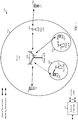
- FIG. 1 shows a wireless communication network 100, which may be an LTE network or some other wireless network.
- Wireless network 100 may include a number of evolved Node Bs (eNBs) 110 and other network entities.
- An eNB is an entity that communicates with user equipments (UEs) and may also be referred to as a base station, a Node B, an access point, etc.
- UEs user equipments
- Each eNB may provide communication coverage for a particular geographic area.
- the term "cell" can refer to a coverage area of an eNB and/or an eNB subsystem serving this coverage area, depending on the context in which the term is used.
- An eNB may provide communication coverage for a macro cell, a pico cell, a femto cell, and/or other types of cell.
- a macro cell may cover a relatively large geographic area (e.g., several kilometers in radius) and may allow unrestricted access by UEs with service subscription.
- a pico cell may cover a relatively small geographic area and may allow unrestricted access by UEs with service subscription.
- a femto cell may cover a relatively small geographic area (e.g., a home) and may allow restricted access by UEs having association with the femto cell (e.g., UEs in a closed subscriber group (CSG)).
- An eNB for a macro cell may be referred to as a macro eNB.
- An eNB for a pico cell may be referred to as a pico eNB.
- An eNB for a femto cell may be referred to as a femto eNB or a home eNB (HeNB).
- HeNB home eNB
- an eNB 110a may be a macro eNB for a macro cell 102a
- an eNB 110b may be a pico eNB for a pico cell 102b
- an eNB 110c may be a femto eNB for a femto cell 102c.
- An eNB may support one or multiple (e.g., three) cells.
- the terms "eNB", “base station” and “cell” may be used interchangeably herein.
- Wireless network 100 may also include relay stations.
- a relay station is an entity that can receive a transmission of data from an upstream station (e.g., an eNB or a UE) and send a transmission of the data to a downstream station (e.g., a UE or an eNB).
- a relay station may also be a UE that can relay transmissions for other UEs.
- a relay station 110d may communicate with macro eNB 110a and a UE 120d in order to facilitate communication between eNB 110a and UE 120d.
- a relay station may also be referred to as a relay eNB, a relay base station, a relay, etc.
- Wireless network 100 may be a heterogeneous network that includes eNBs of different types, e.g., macro eNBs, pico eNBs, femto eNBs, relay eNBs, etc. These different types of eNBs may have different transmit power levels, different coverage areas, and different impact on interference in wireless network 100.
- macro eNBs may have a high transmit power level (e.g., 5 to 40 Watts) whereas pico eNBs, femto eNBs, and relay eNBs may have lower transmit power levels (e.g., 0.1 to 2 Watts).
- a network controller 130 may couple to a set of eNBs and may provide coordination and control for these eNBs.
- Network controller 130 may communicate with the eNBs via a backhaul.
- the eNBs may also communicate with one another, e.g., directly or indirectly via a wireless or wireline backhaul.
- UEs 120 may be dispersed throughout wireless network 100, and each UE may be stationary or mobile.
- a UE may also be referred to as an access terminal, a terminal, a mobile station, a subscriber unit, a station, etc.
- a UE may be a cellular phone, a personal digital assistant (PDA), a wireless modem, a wireless communication device, a handheld device, a laptop computer, a cordless phone, a wireless local loop (WLL) station, a tablet, a smart phone, a netbook, a smartbook, etc.
- PDA personal digital assistant
- WLL wireless local loop
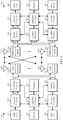
- FIG. 2 shows a block diagram of a design of base station/eNB 110 and UE 120, which may be one of the base stations/eNBs and one of the UEs in FIG. 1 .
- Base station 110 may be equipped with T antennas 234a through 234t
- UE 120 may be equipped with R antennas 252a through 252r, where in general T ⁇ 1 and R ⁇ 1.
- a transmit processor 220 may receive data from a data source 212 for one or more UEs, select one or more modulation and coding schemes (MCS) for each UE based on CQIs received from the UE, process (e.g., encode and modulate) the data for each UE based on the MCS(s) selected for the UE, and provide data symbols for all UEs. Transmit processor 220 may also process system information and control information (e.g., CQI requests, grants, upper layer signaling, etc.) and provide overhead symbols and control symbols. Processor 220 may also generate reference symbols for reference signals (e.g., the CRS) and synchronization signals (e.g., the PSS and SSS).
- MCS modulation and coding schemes
- a transmit (TX) multiple-input multiple-output (MIMO) processor 230 may perform spatial processing (e.g., precoding) on the data symbols using the PMI (Precoding Matrix Indicator) feedback from the UE, the control symbols, the overhead symbols, and/or the reference symbols, if applicable, and may provide T output symbol streams to T modulators (MODs) 232a through 232t.
- Each modulator 232 may process a respective output symbol stream (e.g., for OFDM, etc.) to obtain an output sample stream.
- Each modulator 232 may further process (e.g., convert to analog, amplify, filter, and upconvert) the output sample stream to obtain a downlink signal.
- T downlink signals from modulators 232a through 232t may be transmitted via T antennas 234a through 234t, respectively.
- antennas 252a through 252r may receive the downlink signals from base station 110 and/or other base stations and may provide received signals to demodulators (DEMODs) 254a through 254r, respectively.
- Each demodulator 254 may condition (e.g., filter, amplify, downconvert, and digitize) its received signal to obtain input samples.
- Each demodulator 254 may further process the input samples (e.g., for OFDM, etc.) to obtain received symbols.
- a MIMO detector 256 may obtain received symbols from all R demodulators 254a through 254r, perform MIMO detection on the received symbols if applicable, and provide detected symbols.
- a receive processor 258 may process (e.g., demodulate and decode) the detected symbols, provide decoded data for UE 120 to a data sink 260, and provide decoded control information and system information to a controller/processor 280.
- a channel processor may determine RSRP, RSSI, RSRQ, CQI, etc.
- a transmit processor 264 may receive and process data from a data source 262 and control information (e.g., for reports comprising RSRP, RSSI, RSRQ, CQI, etc.) from controller/processor 280. Processor 264 may also generate reference symbols for one or more reference signals. The symbols from transmit processor 264 may be precoded by a TX MIMO processor 266 if applicable, further processed by modulators 254a through 254r (e.g., for SC-FDM, OFDM, etc.), and transmitted to base station 110.
- control information e.g., for reports comprising RSRP, RSSI, RSRQ, CQI, etc.
- Processor 264 may also generate reference symbols for one or more reference signals.
- the symbols from transmit processor 264 may be precoded by a TX MIMO processor 266 if applicable, further processed by modulators 254a through 254r (e.g., for SC-FDM, OFDM, etc.), and transmitted to base station 110.
- the uplink signals from UE 120 and other UEs may be received by antennas 234, processed by demodulators 232, detected by a MIMO detector 236 if applicable, and further processed by a receive processor 238 to obtain decoded data and control information sent by UE 120.
- Processor 238 may provide the decoded data to a data sink 239 and the decoded control information to controller/processor 240.
- Base station 110 may include communication unit 244 and communicate to network controller 130 via communication unit 244.
- Network controller 130 may include communication unit 294, controller/processor 290, and memory 292.
- Controllers/processors 240 and 280 may direct the operation at base station 110 and UE 120, respectively.
- Processor 240 and/or other processors and modules at base station 110, and/or processor 280 and/or other processors and modules at UE 120, may perform or direct processes for the techniques described herein.
- Memories 242 and 282 may store data and program codes for base station 110 and UE 120, respectively.
- a scheduler 246 may schedule UEs for data transmission on the downlink and/or uplink.
- the base station 110 when transmitting data to the UE 120 the base station 110 may be configured to determining a bundling size based at least in part on a data allocation size and precode data in bundled contiguous resource blocks of the determined bundling size, wherein resource blocks in each bundle are precoded with a common precoding matrix. That is, reference signals such as UE-RS and/or data in the resource blocks are precoded using the same precoder.
- the power level used for the UE-RS in each RB of the bundled RBs may also be the same.
- the UE 120 may be configured to perform complementary processing to decode data transmitted from the base station 110. For example, the UE 120 may be configured to determine a bundling size based on a data allocation size of received data transmitted from a base station in bundles of contiguous resource blocks (RBs), wherein at least one reference signal in resource blocks in each bundle are precoded with a common precoding matrix, estimate at least one precoded channel based on the determined bundling size and one or more reference signals (RSs) transmitted from the base station, and decode the received bundles using the estimated precoded channel.
- RBs resource blocks
- RSs reference signals
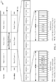
- FIG. 3 shows an exemplary frame structure 300 for FDD in LTE.
- the transmission timeline for each of the downlink and uplink may be partitioned into units of radio frames.
- Each radio frame may have a predetermined duration (e.g., 10 milliseconds (ms)) and may be partitioned into 10 subframes with indices of 0 through 9.
- Each subframe may include two slots.
- Each radio frame may thus include 20 slots with indices of 0 through 19.
- Each slot may include L symbol periods, e.g., seven symbol periods for a normal cyclic prefix (as shown in FIG. 2 ) or six symbol periods for an extended cyclic prefix.
- the 2L symbol periods in each subframe may be assigned indices of 0 through 2L-1.
- an eNB may transmit a primary synchronization signal (PSS) and a secondary synchronization signal (SSS) on the downlink in the center 1.08 MHz of the system bandwidth for each cell supported by the eNB.
- PSS and SSS may be transmitted in symbol periods 6 and 5, respectively, in subframes 0 and 5 of each radio frame with the normal cyclic prefix, as shown in FIG. 3 .
- the PSS and SSS may be used by UEs for cell search and acquisition.
- the eNB may transmit a cell-specific reference signal (CRS) across the system bandwidth for each cell supported by the eNB.
- the CRS may be transmitted in certain symbol periods of each subframe and may be used by the UEs to perform channel estimation, channel quality measurement, and/or other functions.
- the eNB may also transmit a physical broadcast channel (PBCH) in symbol periods 0 to 3 in slot 1 of certain radio frames.
- PBCH physical broadcast channel
- the PBCH may carry some system information.
- the eNB may transmit other system information such as system information blocks (SIBs) on a physical downlink shared channel (PDSCH) in certain subframes.
- SIBs system information blocks
- PDSCH physical downlink shared channel
- the eNB may transmit control information/data on a physical downlink control channel (PDCCH) in the first B symbol periods of a subframe, where B may be configurable for each subframe.
- the eNB may transmit traffic data and/or other data on the PDSCH in the remaining symbol periods of each subframe.
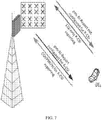
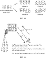
- higher dimension 3D MIMO (as well as "lower dimension” 2D MIMO) systems have been discussed to enhance the peak data rate.
- a grid of 8x8 antennas on a 2D plane as shown in FIG. 4 .
- horizontal beamforming as well as vertical beamforming may be used to exploit beamforming/SDMA gain both in azimuth and elevation.
- 8 antennas at the eNB deployed in azimuth dimension only, allows SDMA or SU-MIMO in horizontal direction.
- Further inclusion of antennas in elevation allows beamforming also in the vertical plane (e.g. to support different floors in a high rise building.
- Certain aspects of the present disclosure provide mechanisms for using different parameters for configuring periodic and aperiodic channel state information (CSI) reporting. This may allow for reductions in feedback overhead for some CSI reporting.
- CSI channel state information
- the number of antenna ports that may be considered may be constrained by the form factor of a base station.
- developing antenna arrays that can perform three dimensional beamforming, which may allow for beamforming horizontally and vertically ( i.e., in the azimuth and elevation dimensions), may be desirable.
- a 2D antenna array with a larger number of antenna ports can be designed to allow for multi-user (MU) 3D MIMO.
- FIG. 5 illustrates an example 2D antenna port structure that may be used for 3D MIMO beamforming.
- the 2D antenna port structure can have eight antenna ports horizontally and four antenna ports vertically, resulting in a total of 32 antenna ports.
- Each antenna port may be formed from a two-element vertical sub-array. Such a sub-array may provide for directional antenna gain in the elevation domain.
- FIGs. 6A and 6B illustrates examples of steering antenna ports to support elevation beamforming and 3D MIMO.
- the antenna ports may be steered to the same direction in elevation. This steering may allow for flexible elevation beamforming and 3D MIMO operations.
- the elevation domain antennas may be steered to different directions. Steering the elevation domain antennas to different directions may allow for the formation of multiple elevation domain subsectors, which may be adapted depending on the location of users and the traffic load.
- the number of channel responses that a terminal may need to estimate may be proportional to the number of transmission antenna ports.
- CQI channel quality indicator
- PMI precoding matrix indicator
- RI rank indicator
- the uplink resources needed for CSI feedback may also scale with the number of antenna ports.
- CSI may be dropped if the amount of data exceeds the total number of multiplexing bits.
- 22 bits may be used to multiplex HARQ-ACKs, scheduling request (SR) bits, and the channel state information, and if the total number of bits for HARQ-ACKs, SR, and CSI exceeds 22 bits, some information may be dropped.
- not all antenna ports may be visible to a UE, and not all antenna ports may be received by a UE with the same signal strength depending on, for example, how the elevation antenna ports are mapped.
- reporting CSI for weak antenna ports may be meaningless.
- beamforming with less antenna ports may achieve a sufficient beamforming gain and capacity. These UEs may not need provide CSI feedback for beamforming from all transmission antenna ports.
- Antenna selection may be applied for CSI measurement and feedback, for example, when a large antenna array is used at a base station for 3D MIMO transmissions.
- a BS may configure the CSI reporting mode to reduce CSI feedback overhead. For example, if a precoding matrix indicator (PMI) or rank indicator (RI) report (pmi-RI-Report) parameter is not configured for CSI reporting, a UE may report only transmission diversity channel quality indicator (TX Div CQI), assuming no precoding, and the UE need not report PMI and RI. Alternatively, the UE may feedback precoded CQI and antenna port number dependent PMI and/or RI to the eNB. These reporting modes imply that transmission beamforming may not be based on feedback from a UE if a pmi-RI-Report parameter is not configured for CSI reporting. Alternatively, a fewer number of antenna ports may be configured for CSI feedback, which may restrict the use of a large number of antenna ports for 3D MIMO.
- PMI precoding matrix indicator
- RI rank indicator
- a UE may report only transmission diversity channel quality indicator (TX Div CQI), assuming no precoding, and the
- periodic and aperiodic CSI reporting may be configured with different CSI parameters.
- Periodic CSI reporting may provide limited CSI for large numbers of antenna ports for 3D MIMO operations, with some performance degradation, and aperiodic CSI reporting using PUSCH may provide full CSI for all configured antenna ports.
- Configuring periodic and aperiodic CSI reporting with different parameters may, for example, reduce periodic CSI feedback overhead on PUCCH.
- the pmi-RI-Report parameter for 3D MIMO-capable UEs may be configured separately for periodic and aperiodic CSI reporting.
- the pmi-RI-Report parameter may be configured for aperiodic CSI reporting using PUSCH but not configured for periodic CSI reporting using PUCCH.
- 3D MIMO-capable UEs may be configured for periodic and aperiodic CSI reporting with different numbers of CSI-RS antenna ports.
- the antenna ports configured for periodic CSI reporting may be a subset of the antenna ports configured for aperiodic CSI reporting. The subset may be configured by an eNB (e.g., using higher layer signaling) or autonomously by a UE.
- Periodic CQI reporting using PUSCH may be configured with the same CSI reporting parameters used for configuring aperiodic CSI reporting.
- FIG. 7 illustrates an example of separately configuring a pmi-RI-Report parameter for periodic and aperiodic CSI reporting.
- a UE can be configured with two pmi-RI-Report parameters.
- An example configuration may entail reporting CQI alone in periodic CSI reporting and reporting CQI, PMI, and RI in aperiodic reporting. Such a configuration may reduce the periodic CSI payload and may cause periodic CSI reporting to not be dependent on the number of CSI-RS antenna ports.
- Configuring periodic and aperiodic CSI reporting with different parameters may, in some embodiments, entail the use of different antenna selections for periodic and aperiodic CSI reporting.
- Antenna selection for CSI feedback may be performed by either a base station or a UE. Regardless of whether antenna selection is performed by a base station or UE, the UE may be configured with a full set of CSI-RS antenna ports which may be used for aperiodic CSI reporting.
- antenna selection performed by a base station may entail the following procedure.
- a BS may transmit a CSI measurement configuration message to a UE.
- the CSI measurement message may comprise a time-frequency resource configuration and a total number of CSI-RS antenna ports that may be used for aperiodic CSI measurement and reporting.
- SRS uplink received sounding reference signals
- the BS can determine a subset of antenna ports for periodic CSI feedback for the UE.
- the UE may receive a message from the BS indicating the subset of antenna ports; for example, the message may comprise a bitmap of the antenna ports, where a value of "1" represents an antenna port that may be used for periodic CSI feedback and a value of "0" represents an antenna port that may not be used for periodic CSI feedback.
- the UE may perform channel measurement for the subset of antenna ports. Channel measurement may be performed by assuming that downlink data may be transmitted only from the subset of antenna ports, and CSI reporting may be generated by treating transmissions from antennas outside the subset ( i.e., ports not used for periodic CSI feedback) as interference to the subset of antenna ports. Based on uplink measurements, the BS may update the subset of antenna ports selected for periodic CSI feedback.
- FIG. 8 illustrates an example of antenna selection performed by a BS for configuring and performing periodic and aperiodic CSI reporting by a UE.
- a first UE may be configured to use a first set of antenna ports (e.g ., antenna ports 0-15), and a second UE may be configured to use a second set of antenna ports ( e.g ., antenna ports 16-31) for periodic CSI reporting.
- the first and second UEs may feedback periodic CSI for the selected antenna ports.
- the BS may perform user pairing and scheduling and may construct beamforming vectors for the base stations.
- W 11 and W 22 may each comprise 16x1 precoding vectors.
- a UE may perform antenna selection for periodic and aperiodic CSI reporting.
- the UE receives a CSI measurement configuration from the BS, which may indicate the total number of CSI-RS antenna ports and a time-frequency resource configuration.
- the UE may measure received signal power for each antenna port and select a set of antenna ports based on these measurements. For example, for periodic CSI reporting, the UE may select a set of antenna ports with relatively strong received power measurements.
- the UE may report the measured CSI for the selected antenna ports and may also report to the BS an indication of the antenna port selection (e.g., a bitmap such as that described above).
- FIG. 9 illustrates an example of antenna selection performed by a UE for configuring and performing periodic and aperiodic CSI reporting.
- a number of UEs may be configured with a total number of antenna ports.
- a BS may have a total of 32 antenna ports and may use, for example, multiple elevation subvectors.
- a first UE may determine that a first set of ports have a strongest received signal power (e.g. , ports 0-7) and select the first set of ports for periodic CSI reporting.
- a second UE may determine that a second set of ports have a strongest received signal power ( e.g ., ports 16-19 and 28-31) and select the second set of ports for periodic CSI reporting.
- the UEs may measure and report CSI, including CQI, PMI, and/or RI, of the selected antenna ports to the BS, as well as an indication of the antenna port selection.
- bitmap pattern for feedback of antenna port selection may be costly, as a bitmap pattern may entail the use of a large number of bits (for example, one bit for each antenna). It may be desirable to reduce the amount of resources used to signal antenna selection.
- codebooks associated with PMI may be determined byarray structure.
- DFT discrete Fourier transform
- UAA uniform linear array
- multiple codebook sets may need to be defined for different array structures. Defining multiple codebook sets may increase complexity. To minimize increases in complexity, it may be desirable to restrict antenna port selection for periodic CSI reporting.
- FIG. 10 illustrates an example of antenna selection options that may be used in a 16-port 2D uniform planar array (UPA).
- the antenna selection options may result in the 16-port UPA falling back to an 8-port ULA where a common codebook structure for the selected eight ports can be defined.
- the UE need only provide feedback of the periodic CSI port selection, which may comprise a smaller number of bits than a bitmap representing the antenna selection. For example, for a 16-port antenna array and four port selection options, feedback of the port selection may comprise two bits rather than 16 bits.
- periodic CSI reportin configuration may entail single frequency network (SFN)-like precoding.
- SFN-like precoding may entail dividing the configured CSI-RS antenna ports into a number of antenna groups. For example, the antenna ports may be divided into groups by column or row of a 2D UPA.
- Each of the antenna groups may employ the same precoding, and a UE may select an antenna group by assuming that each antenna group uses the same precoding and selecting an antenna group based on the precoding. For example, UE k may report a common precoding matrix W k for the B antenna groups.
- FIG. 11 illustrates an example of SFN-like precoding for periodic CSI reporting.
- Two groups of antenna ports are shown; however, it may be recognized that a BS can configure any number of groups of antenna ports.
- the BS may construct a transmission precoding vector W (K) for the antenna ports.
- W k W k 0 0 W k
- FIG. 12 illustrates an example structure for configuring CSI-RS resources.
- up to 8 non-zero power (NZP) CSI-RS antenna ports can be configured for each CSI-RS resource.
- the resourceConfig element may define the resource elements in the frequency domain that can be used for CSI-RS transmission, and the subframeConfig element may define the subframes in the time domain that can be used for CSI-RS.
- the antennaPortsCount element can be extended to support larger CSI-RS antenna port configurations. Extending the antennaPortsCount element may entail a change to the resourceConfig element, which may be restricted to a maximum of 8 port mappings to resource elements.
- a composite CSI-RS resource with a large number of CSI-RS antenna ports can be constructed from multiple CSI-RS resources having a smaller number of CSI-RS antenna ports.
- FIG. 13 illustrates an example structure for configuring a larger number of CSI-RS ports. Multiple NZP-CSI-RS resources may be aggregated into an NZP-CSI-RS configuration. For example, as illustrated, to support a 16 CSI-RS port configuration, two NZP-CSI-RS resources (e.g ., two sets of antennaPortsCount, resourceConfig, and subframeConfig elements) may be aggregated.
- FIG. 14 illustrates another example structure for configuring a larger number of CSI-RS ports. Multiple NZP-CSI-RS resources may be included in a CSI process.
- Increasing the size of the NZP-CSI-RS configuration may cause PDSCH rate matching by legacy UEs (i.e., non-3D-MIMO-capable UEs) to not be performed correctly. Data puncturing may not provide good downlink performance if the reference signal overhead per resource block is large.
- providing for successful PDCCH rate matching by legacy UEs may entail spreading CSI-RS ports to multiple subframes. Spreading CSI-RS ports across subframes may allow for the maintenance of a small reference signal overhead for each resource block. For example, spreading CSI-RS ports to multiple subframes may be performed such that the overhead is less than or equal to 8 resource elements, per resource block, per subframe to provide for an acceptable performance impact on legacy UEs.
- configuration of a zero power (ZP) CSI-RS resource can include the resources reserved for NZP-CSI-RS ports not configured for use by legacy UEs.
- FIG. 15 illustrates an example NZP-CSI-RS configuration for a 16 port NZP-CSI-RS configuration.
- legacy and 3D MIMO UEs can share the same NZP-CSI-RS resources.
- the NZP-CSI-RS resources for 3D MIMO UEs can overlap with the ZP-CSI-RS resources for legacy UEs.
- legacy UEs can correctly perform PDSCH rate matching around the 16 port configuration for 3D MIMO UEs.
- FIG. 16 illustrates example operations 1600 that may be performed by a base station (e.g ., an eNodeB) to provide for reductions in overhead for CSI reporting, in accordance with aspects of the present disclosure.
- Operations 1600 may begin at 1602, where a BS configures a UE that is capable of 3D MIMO with different parameters for periodic and aperiodic CSI reporting, wherein the different parameters indicate at least one of what resources to measure or what information to report.
- the BS receives periodic and aperiodic CSI reporting from the UE according to the configuration.
- FIG. 17 illustrates example operations 1700 that may be performed by a user equipment to provide for reductions in overhead for CSI reporting, in accordance with aspects of the present disclosure.
- Operations 1700 may begin at 1702, where a UE receives a configuration, from a BS, of different parameters for periodic and aperiodic CSI reporting, wherein the different parameters indicate at least one of what resources to measure or what information to report.
- the UE measures and reports periodic and aperiodic CSI according to the configuration.
- DSP digital signal processor
- ASIC application specific integrated circuit
- FPGA field programmable gate array
- a general-purpose processor may be a microprocessor, but in the alternative, the processor may be any conventional processor, controller, microcontroller or state machine.
- a processor may also be implemented as a combination of computing devices, e.g., a combination of a DSP and a microprocessor, a plurality of microprocessors, one or more microprocessors in conjunction with a DSP core, or any other such configuration.
- a software module may reside in RAM memory, flash memory, ROM memory, EPROM memory, EEPROM memory, registers, hard disk, a removable disk, a CD-ROM or any other form of storage medium known in the art.
- An exemplary storage medium is coupled to the processor such that the processor can read information from, and/or write information to, the storage medium.
- the storage medium may be integral to the processor.
- the processor and the storage medium may reside in an ASIC.
- the ASIC may reside in a user terminal.
- the processor and the storage medium may reside as discrete components in a user terminal.
- the functions described may be implemented in hardware, software, firmware or any combination thereof. If implemented in software, the functions may be stored on or transmitted over as one or more instructions or code on a computer-readable medium.
- Computer-readable media includes both computer storage media and communication media including any medium that facilitates transfer of a computer program from one place to another.
- a storage media may be any available media that can be accessed by a general purpose or special purpose computer.
- such computer-readable media can comprise RAM, ROM, EEPROM, CD-ROM or other optical disk storage, magnetic disk storage or other magnetic storage devices, or any other medium that can be used to carry or store desired program code means in the form of instructions or data structures and that can be accessed by a general-purpose or special-purpose computer, or a general-purpose or special-purpose processor. Also, any connection is properly termed a computer-readable medium.
- Disk and disc includes compact disc (CD), laser disc, optical disc, digital versatile disc (DVD), floppy disk and blu-ray disc where disks usually reproduce data magnetically, while discs reproduce data optically with lasers. Combinations of the above should also be included within the scope of computer-readable media.
Priority Applications (1)
| Application Number | Priority Date | Filing Date | Title |
|---|---|---|---|
| HUE14892803A HUE049819T2 (hu) | 2014-05-22 | 2014-05-22 | Periodikus és aperiodikus csatornaállapot információ (CSI) jelentés MIMO-hoz |
Applications Claiming Priority (1)
| Application Number | Priority Date | Filing Date | Title |
|---|---|---|---|
| PCT/CN2014/078097 WO2015176266A1 (en) | 2014-05-22 | 2014-05-22 | Periodic and aperiodic channel state information (csi) reporting for mimo |
Publications (3)
| Publication Number | Publication Date |
|---|---|
| EP3146739A1 EP3146739A1 (en) | 2017-03-29 |
| EP3146739A4 EP3146739A4 (en) | 2017-12-27 |
| EP3146739B1 true EP3146739B1 (en) | 2020-04-29 |
Family
ID=54553221
Family Applications (1)
| Application Number | Title | Priority Date | Filing Date |
|---|---|---|---|
| EP14892803.9A Active EP3146739B1 (en) | 2014-05-22 | 2014-05-22 | Periodic and aperiodic channel state information (csi) reporting for mimo |
Country Status (8)
| Country | Link |
|---|---|
| US (2) | US11317306B2 (zh) |
| EP (1) | EP3146739B1 (zh) |
| JP (1) | JP6776127B2 (zh) |
| KR (1) | KR102197451B1 (zh) |
| CN (2) | CN112653495B (zh) |
| ES (1) | ES2808598T3 (zh) |
| HU (1) | HUE049819T2 (zh) |
| WO (1) | WO2015176266A1 (zh) |
Families Citing this family (51)
| Publication number | Priority date | Publication date | Assignee | Title |
|---|---|---|---|---|
| EP2475106A1 (en) * | 2006-02-28 | 2012-07-11 | Rotani Inc. | Methods and apparatus for overlapping mimo antenna physical sectors |
| US9999073B2 (en) * | 2014-11-18 | 2018-06-12 | Telefonaktiebolaget Lm Ericsson (Publ) | Signaling adapted CSI-RS periodicities in active antenna systems |
| US20160149628A1 (en) * | 2014-11-25 | 2016-05-26 | Intel Corporation | Channel state information (csi) reporting for carrier aggregation |
| US10355757B2 (en) * | 2015-01-30 | 2019-07-16 | Nokia Solutions And Networks Oy | Method and apparatus for performing radio-resource-management measurements |
| US10084577B2 (en) | 2015-01-30 | 2018-09-25 | Motorola Mobility Llc | Method and apparatus for signaling aperiodic channel state indication reference signals for LTE operation |
| US9743392B2 (en) | 2015-01-30 | 2017-08-22 | Motorola Mobility Llc | Method and apparatus for signaling aperiodic channel state indication reference signals for LTE operation |
| US11218261B2 (en) * | 2015-06-01 | 2022-01-04 | Qualcomm Incorporated | Channel state information reference signals in contention-based spectrum |
| JP2017050758A (ja) * | 2015-09-03 | 2017-03-09 | ソニー株式会社 | 端末装置及び無線通信装置 |
| EP3350941A1 (en) * | 2015-09-14 | 2018-07-25 | Telefonaktiebolaget LM Ericsson (publ) | Network node, wireless device and methods thereby to indicate a first set of antenna ports and a second set of antenna ports |
| CN106559120B (zh) * | 2015-09-25 | 2021-06-15 | 索尼公司 | 无线通信系统中的电子设备和无线通信方法 |
| US11212039B2 (en) * | 2016-01-05 | 2021-12-28 | Intel Corporation | Acknowledgment management techniques for uplink multi-user transmissions |
| WO2017136749A1 (en) * | 2016-02-03 | 2017-08-10 | Docomo Innovations, Inc. | User equipment and method for wireless communication |
| CN107204794B (zh) * | 2016-03-18 | 2020-02-21 | 电信科学技术研究院 | 一种csi反馈方法及装置 |
| CN107370582A (zh) * | 2016-05-12 | 2017-11-21 | 株式会社Ntt都科摩 | 参考信号发送方法、检测方法、基站和移动台 |
| EP3455965B1 (en) * | 2016-05-13 | 2023-08-09 | Nokia Technologies Oy | Flexible channel state reporting |
| CN110326228B (zh) * | 2016-08-11 | 2023-06-13 | 交互数字专利控股公司 | 用于新无线电的csi反馈方法和装置 |
| WO2018062910A1 (ko) * | 2016-09-29 | 2018-04-05 | 엘지전자 주식회사 | 무선 통신 시스템에서 개루프 mimo 전송을 위한 하이브리드 csi 의 피드백 방법 및 이를 위한 장치 |
| JP7170643B2 (ja) | 2016-12-23 | 2022-11-14 | オッポ広東移動通信有限公司 | データ伝送方法、ネットワーク装置と端末装置 |
| US10205504B2 (en) * | 2017-02-03 | 2019-02-12 | At&T Intellectual Property I, L.P. | Facilitation of computational complexity reduction for periodic and aperiodic channel state information reporting in 5G or other next generation network |
| CN108631847B (zh) * | 2017-03-24 | 2021-06-01 | 华为技术有限公司 | 传输信道状态信息的方法、终端设备和网络设备 |
| JP2018207333A (ja) * | 2017-06-06 | 2018-12-27 | 富士通株式会社 | 基地局、無線端末、無線通信システム、及び通信制御方法 |
| US10187131B2 (en) * | 2017-06-09 | 2019-01-22 | At&T Intellectual Property I, L.P. | Facilitation of rank and precoding matrix indication determinations for multiple antenna systems with aperiodic channel state information reporting in 5G or other next generation networks |
| US10153814B1 (en) * | 2017-06-13 | 2018-12-11 | Corning Incorporated | Massive multiple-input multiple-output (M-MIMO) wireless distribution system (WDS) and related methods for optimizing the M-MIMO WDS |
| EP3639401A1 (en) * | 2017-06-16 | 2020-04-22 | Intel Corporation | Channel state information concatenation and antenna port measurement |
| CN109474312B (zh) * | 2017-09-07 | 2020-10-02 | 上海朗帛通信技术有限公司 | 一种被用于无线通信的用户、基站中的方法和装置 |
| US11375391B2 (en) | 2017-09-29 | 2022-06-28 | Lg Electronics Inc. | Method for reporting aperiodic CSI in wireless communication system and device therefor |
| AU2017433231B2 (en) * | 2017-09-30 | 2022-12-22 | Guangdong Oppo Mobile Telecommunications Corp., Ltd. | Method for calculating channel quality indicator (CQI), terminal device, and network device |
| WO2019068212A1 (en) * | 2017-10-02 | 2019-04-11 | Qualcomm Incorporated | OMISSION OF CHANNEL STATE INFORMATION (CSI) OF SUB-BAND FOR TYPE II CSI |
| CN109672463B (zh) | 2017-10-17 | 2020-11-06 | 上海朗帛通信技术有限公司 | 一种被用于无线通信的用户、基站中的方法和装置 |
| CN111434067B (zh) * | 2017-11-09 | 2021-08-31 | 北京小米移动软件有限公司 | 基于无线装置能力的通信方法、装置及基站 |
| CN113472410B (zh) * | 2018-01-12 | 2023-07-18 | 华为技术有限公司 | 无线通信系统中信道状态信息反馈方法和装置 |
| US11923924B2 (en) * | 2018-02-26 | 2024-03-05 | Parallel Wireless, Inc. | Miniature antenna array with polar combining architecture |
| CN108390694B (zh) | 2018-03-16 | 2020-05-05 | Oppo广东移动通信有限公司 | 多路选择开关、射频系统以及无线通信设备 |
| CN108199730B (zh) | 2018-03-16 | 2020-11-06 | Oppo广东移动通信有限公司 | 多路选择开关、射频系统以及无线通信设备 |
| CN108462507B (zh) * | 2018-03-16 | 2020-09-04 | Oppo广东移动通信有限公司 | 多路选择开关、射频系统以及无线通信设备 |
| CN110278007B (zh) | 2018-03-16 | 2020-10-20 | Oppo广东移动通信有限公司 | 多路选择开关及相关产品 |
| CN108199729B (zh) | 2018-03-16 | 2020-09-04 | Oppo广东移动通信有限公司 | 多路选择开关、射频系统和无线通信设备 |
| US11425735B2 (en) * | 2018-04-05 | 2022-08-23 | Qualcomm Incorporated | Scheduling channel state information (CSI) processes in association with periodic traffic in a CoMP network |
| US10819410B2 (en) * | 2018-04-06 | 2020-10-27 | Qualcomm Incorporated | Selecting physical uplink control channel (PUCCH) resources for channel state information |
| CN108833061B (zh) * | 2018-04-12 | 2022-02-18 | 中兴通讯股份有限公司 | 一种信道状态信息报告方法、装置、接收方法和装置 |
| CN112262588B (zh) * | 2018-06-14 | 2022-05-06 | 华为技术有限公司 | 信道状态信息传输方法、相关装置及通信系统 |
| US11637732B2 (en) | 2018-07-18 | 2023-04-25 | Samsung Electronics Co., Ltd. | Method and apparatus for high-resolution CSI reporting in advanced wireless communication systems |
| CN110768701B (zh) * | 2018-07-27 | 2022-10-28 | 中兴通讯股份有限公司 | 信道状态处理方法及装置、系统、终端、基站、存储介质 |
| EP3817242A4 (en) * | 2018-07-27 | 2021-08-11 | LG Electronics Inc. | METHOD AND DEVICE FOR REPORTING CHANNEL STATUS INFORMATION IN A WIRELESS COMMUNICATION SYSTEM |
| CN114257284A (zh) | 2018-09-21 | 2022-03-29 | 阿里斯卡尔股份有限公司 | 信道状态信息参考信号 |
| WO2020128602A1 (en) * | 2018-12-21 | 2020-06-25 | Telefonaktiebolaget Lm Ericsson (Publ) | Csi-rs resource reuse |
| WO2020150884A1 (en) * | 2019-01-22 | 2020-07-30 | Qualcomm Incorporated | Csi processing for fine csi granularity |
| US11317245B2 (en) * | 2019-03-11 | 2022-04-26 | Qualcomm Incorporated | Time-domain waveform reporting for positioning |
| EP4089930A4 (en) * | 2020-01-23 | 2023-01-11 | Huawei Technologies Co., Ltd. | COMMUNICATION METHOD AND COMMUNICATION DEVICE |
| US11805540B2 (en) * | 2020-04-24 | 2023-10-31 | Qualcomm Incorporated | Techniques for selection or indication of a channel state information report parameter |
| EP4285494A1 (en) * | 2021-01-29 | 2023-12-06 | QUALCOMM Incorporated | Techniques for determining channel state information using a neural network model |
Citations (1)
| Publication number | Priority date | Publication date | Assignee | Title |
|---|---|---|---|---|
| WO2013144360A1 (en) * | 2012-03-30 | 2013-10-03 | Nokia Siemens Networks Oy | Codebook feedback method for per-user elevation beamforming |
Family Cites Families (29)
| Publication number | Priority date | Publication date | Assignee | Title |
|---|---|---|---|---|
| US7721291B2 (en) | 2004-10-15 | 2010-05-18 | International Business Machines Corporation | Apparatus, system, and method for automatically minimizing real-time task latency and maximizing non-real time task throughput |
| US8483186B2 (en) | 2007-12-10 | 2013-07-09 | Mitsubishi Electric Research Laboratories, Inc. | Method and system for generating antenna selection signals in wireless networks |
| KR101476202B1 (ko) | 2008-01-08 | 2014-12-24 | 엘지전자 주식회사 | 주기적/비주기적 채널상태정보 송수신 방법 |
| PL2908585T3 (pl) * | 2009-06-19 | 2017-12-29 | Interdigital Patent Holdings, Inc. | Sygnalizowanie informacji sterującej łączem wysyłania w LTE-A |
| CN102870362B (zh) | 2010-01-08 | 2014-07-30 | 华为技术有限公司 | 信道状态信息上报方法及设备 |
| US9083501B2 (en) * | 2010-04-05 | 2015-07-14 | Qualcomm Incorporated | Feedback of control information for multiple carriers |
| US8638684B2 (en) | 2010-04-05 | 2014-01-28 | Qualcomm | Aperiodic channel state information request in wireless communication |
| US9515773B2 (en) * | 2010-04-13 | 2016-12-06 | Qualcomm Incorporated | Channel state information reporting in a wireless communication network |
| CN102082636B (zh) * | 2010-08-16 | 2013-05-08 | 电信科学技术研究院 | 一种信道状态信息csi反馈指示方法和基站及系统 |
| US8732711B2 (en) | 2010-09-24 | 2014-05-20 | Nvidia Corporation | Two-level scheduler for multi-threaded processing |
| US8732713B2 (en) | 2010-09-29 | 2014-05-20 | Nvidia Corporation | Thread group scheduler for computing on a parallel thread processor |
| US20120127869A1 (en) * | 2010-11-22 | 2012-05-24 | Sharp Laboratories Of America, Inc. | Multiple channel state information (csi) reporting on the physical uplink shared channel (pusch) with carrier aggregation |
| US8995400B2 (en) | 2011-02-11 | 2015-03-31 | Qualcomm Incorporated | Method and apparatus for enabling channel and interference estimations in macro/RRH system |
| US10085164B2 (en) | 2011-04-28 | 2018-09-25 | Qualcomm Incorporated | System and method for managing invalid reference subframes for channel state information feedback |
| CN102377469B (zh) | 2011-09-30 | 2018-08-28 | 中兴通讯股份有限公司 | 一种多点信道信息反馈方法、系统及终端 |
| US9209950B2 (en) | 2011-10-03 | 2015-12-08 | Qualcomm Incorporated | Antenna time offset in multiple-input-multiple-output and coordinated multipoint transmissions |
| US9451488B2 (en) * | 2012-01-20 | 2016-09-20 | Lg Electronics Inc. | Method and apparatus for channel state information feedback in wireless communication system |
| US9621318B2 (en) * | 2012-02-01 | 2017-04-11 | Samsung Electronics Co., Ltd | Method and device for transmitting and receiving channel state information in downlink coordinated multi-point system |
| US9681425B2 (en) | 2012-05-11 | 2017-06-13 | Qualcomm Incorporated | Rank-specific feedback for improved MIMO support |
| US9788226B2 (en) * | 2012-06-05 | 2017-10-10 | Lg Electronics Inc. | Method and apparatus for reporting channel state information |
| US9716539B2 (en) * | 2012-07-02 | 2017-07-25 | Lg Electronics Inc. | Method and device for reporting channel state information in wireless communication system |
| US9225478B2 (en) | 2012-07-02 | 2015-12-29 | Intel Corporation | Supporting measurments and feedback for 3D MIMO with data transmission optimization |
| US9106386B2 (en) * | 2012-08-03 | 2015-08-11 | Intel Corporation | Reference signal configuration for coordinated multipoint |
| JP6127146B2 (ja) * | 2012-09-28 | 2017-05-10 | インターデイジタル パテント ホールディングス インコーポレイテッド | 多次元アンテナ構成を使用する無線通信 |
| US9596065B2 (en) * | 2012-10-24 | 2017-03-14 | Qualcomm Incorporated | Enhanced SRS transmission for MIMO operation in LTE-A |
| US20140313912A1 (en) * | 2013-01-28 | 2014-10-23 | Telefonaktiebolaget L M Ericsson (Publ) | Configuration of Interference Averaging for Channel Measurements |
| US9461723B2 (en) * | 2013-03-29 | 2016-10-04 | Intel IP Corporation | Orthologonal beamforming for multiple user multiple-input and multiple-output (MU-MIMO) |
| US10489200B2 (en) | 2013-10-23 | 2019-11-26 | Nvidia Corporation | Hierarchical staging areas for scheduling threads for execution |
| US9904580B2 (en) | 2015-05-29 | 2018-02-27 | International Business Machines Corporation | Efficient critical thread scheduling for non-privileged thread requests |
-
2014
- 2014-05-22 WO PCT/CN2014/078097 patent/WO2015176266A1/en active Application Filing
- 2014-05-22 CN CN202011449297.1A patent/CN112653495B/zh active Active
- 2014-05-22 CN CN201480078925.6A patent/CN106465097A/zh active Pending
- 2014-05-22 EP EP14892803.9A patent/EP3146739B1/en active Active
- 2014-05-22 US US15/313,003 patent/US11317306B2/en active Active
- 2014-05-22 JP JP2016568539A patent/JP6776127B2/ja active Active
- 2014-05-22 ES ES14892803T patent/ES2808598T3/es active Active
- 2014-05-22 KR KR1020167031904A patent/KR102197451B1/ko active IP Right Grant
- 2014-05-22 HU HUE14892803A patent/HUE049819T2/hu unknown
-
2022
- 2022-04-21 US US17/660,050 patent/US20220248247A1/en active Pending
Patent Citations (1)
| Publication number | Priority date | Publication date | Assignee | Title |
|---|---|---|---|---|
| WO2013144360A1 (en) * | 2012-03-30 | 2013-10-03 | Nokia Siemens Networks Oy | Codebook feedback method for per-user elevation beamforming |
Also Published As
| Publication number | Publication date |
|---|---|
| CN112653495B (zh) | 2023-08-29 |
| JP6776127B2 (ja) | 2020-10-28 |
| KR102197451B1 (ko) | 2020-12-31 |
| CN106465097A (zh) | 2017-02-22 |
| EP3146739A4 (en) | 2017-12-27 |
| US11317306B2 (en) | 2022-04-26 |
| HUE049819T2 (hu) | 2020-10-28 |
| KR20170009860A (ko) | 2017-01-25 |
| ES2808598T3 (es) | 2021-03-01 |
| WO2015176266A1 (en) | 2015-11-26 |
| JP2017521896A (ja) | 2017-08-03 |
| CN112653495A (zh) | 2021-04-13 |
| US20170164226A1 (en) | 2017-06-08 |
| EP3146739A1 (en) | 2017-03-29 |
| US20220248247A1 (en) | 2022-08-04 |
Similar Documents
| Publication | Publication Date | Title |
|---|---|---|
| US20220248247A1 (en) | Periodic and aperiodic channel state information (csi) reporting for mimo | |
| US11811702B2 (en) | System and method for flexible channel state information-reference signal transmission | |
| EP2951933B1 (en) | 3d mimo csi feedback based on virtual elevation ports | |
| KR102402529B1 (ko) | 감소된 밀도 csi-rs를 위한 메커니즘들 | |
| US10659981B2 (en) | Method, system, and device for transmitting preamble signal and for signal measurement | |
| KR102372115B1 (ko) | Fd-mimo 에 대한 강화된 csi 절차들 | |
| US10826577B2 (en) | Enhanced CSI feedback for FD-MIMO | |
| EP3198743B1 (en) | Apparatus and method for full-dimensional mimo with one-dimensional csi feedback | |
| EP2813005B1 (en) | Gain normalization correction of pmi and cqi feedback for base station with antenna array | |
| WO2017117777A1 (en) | Enhanced csi feedback for fd-mimo | |
| EP3857785B1 (en) | Restricting sounding reference signal (srs) power control configurations | |
| WO2022009151A1 (en) | Shared csi-rs for partial-reciprocity based csi feedback | |
| JP6648313B2 (ja) | Mimoのための周期および非周期チャネル状態情報(csi)報告 | |
| BR112016025946B1 (pt) | Relatório de informação de estado de canal (csi) periódico e aperiódico para mimo |
Legal Events
| Date | Code | Title | Description |
|---|---|---|---|
| STAA | Information on the status of an ep patent application or granted ep patent |
Free format text: STATUS: THE INTERNATIONAL PUBLICATION HAS BEEN MADE |
|
| PUAI | Public reference made under article 153(3) epc to a published international application that has entered the european phase |
Free format text: ORIGINAL CODE: 0009012 |
|
| STAA | Information on the status of an ep patent application or granted ep patent |
Free format text: STATUS: REQUEST FOR EXAMINATION WAS MADE |
|
| 17P | Request for examination filed |
Effective date: 20161019 |
|
| AK | Designated contracting states |
Kind code of ref document: A1 Designated state(s): AL AT BE BG CH CY CZ DE DK EE ES FI FR GB GR HR HU IE IS IT LI LT LU LV MC MK MT NL NO PL PT RO RS SE SI SK SM TR |
|
| AX | Request for extension of the european patent |
Extension state: BA ME |
|
| DAX | Request for extension of the european patent (deleted) | ||
| A4 | Supplementary search report drawn up and despatched |
Effective date: 20171129 |
|
| RIC1 | Information provided on ipc code assigned before grant |
Ipc: H04B 7/0452 20170101ALN20171123BHEP Ipc: H04W 24/10 20090101ALI20171123BHEP Ipc: H04B 7/06 20060101ALI20171123BHEP Ipc: H04L 5/00 20060101AFI20171123BHEP Ipc: H04W 88/08 20090101ALN20171123BHEP Ipc: H04B 7/04 20170101ALN20171123BHEP Ipc: H04L 1/00 20060101ALN20171123BHEP |
|
| STAA | Information on the status of an ep patent application or granted ep patent |
Free format text: STATUS: EXAMINATION IS IN PROGRESS |
|
| 17Q | First examination report despatched |
Effective date: 20190115 |
|
| REG | Reference to a national code |
Ref country code: DE Ref legal event code: R079 Ref document number: 602014064754 Country of ref document: DE Free format text: PREVIOUS MAIN CLASS: H04W0008220000 Ipc: H04L0005000000 |
|
| RIC1 | Information provided on ipc code assigned before grant |
Ipc: H04B 7/0452 20170101ALN20191014BHEP Ipc: H04B 7/06 20060101ALI20191014BHEP Ipc: H04B 7/0456 20170101ALI20191014BHEP Ipc: H04W 88/08 20090101ALN20191014BHEP Ipc: H04L 5/00 20060101AFI20191014BHEP Ipc: H04B 7/04 20170101ALN20191014BHEP Ipc: H04L 1/00 20060101ALI20191014BHEP |
|
| GRAP | Despatch of communication of intention to grant a patent |
Free format text: ORIGINAL CODE: EPIDOSNIGR1 |
|
| STAA | Information on the status of an ep patent application or granted ep patent |
Free format text: STATUS: GRANT OF PATENT IS INTENDED |
|
| RIC1 | Information provided on ipc code assigned before grant |
Ipc: H04B 7/06 20060101ALI20191022BHEP Ipc: H04L 5/00 20060101AFI20191022BHEP Ipc: H04W 88/08 20090101ALN20191022BHEP Ipc: H04L 1/00 20060101ALI20191022BHEP Ipc: H04B 7/0452 20170101ALN20191022BHEP Ipc: H04B 7/0456 20170101ALI20191022BHEP Ipc: H04B 7/04 20170101ALN20191022BHEP |
|
| INTG | Intention to grant announced |
Effective date: 20191122 |
|
| GRAS | Grant fee paid |
Free format text: ORIGINAL CODE: EPIDOSNIGR3 |
|
| GRAA | (expected) grant |
Free format text: ORIGINAL CODE: 0009210 |
|
| STAA | Information on the status of an ep patent application or granted ep patent |
Free format text: STATUS: THE PATENT HAS BEEN GRANTED |
|
| AK | Designated contracting states |
Kind code of ref document: B1 Designated state(s): AL AT BE BG CH CY CZ DE DK EE ES FI FR GB GR HR HU IE IS IT LI LT LU LV MC MK MT NL NO PL PT RO RS SE SI SK SM TR |
|
| REG | Reference to a national code |
Ref country code: GB Ref legal event code: FG4D |
|
| REG | Reference to a national code |
Ref country code: CH Ref legal event code: EP |
|
| REG | Reference to a national code |
Ref country code: DE Ref legal event code: R096 Ref document number: 602014064754 Country of ref document: DE |
|
| REG | Reference to a national code |
Ref country code: AT Ref legal event code: REF Ref document number: 1264921 Country of ref document: AT Kind code of ref document: T Effective date: 20200515 |
|
| REG | Reference to a national code |
Ref country code: IE Ref legal event code: FG4D |
|
| REG | Reference to a national code |
Ref country code: FI Ref legal event code: FGE |
|
| REG | Reference to a national code |
Ref country code: NL Ref legal event code: FP |
|
| REG | Reference to a national code |
Ref country code: LT Ref legal event code: MG4D |
|
| REG | Reference to a national code |
Ref country code: HU Ref legal event code: AG4A Ref document number: E049819 Country of ref document: HU |
|
| PG25 | Lapsed in a contracting state [announced via postgrant information from national office to epo] |
Ref country code: LT Free format text: LAPSE BECAUSE OF FAILURE TO SUBMIT A TRANSLATION OF THE DESCRIPTION OR TO PAY THE FEE WITHIN THE PRESCRIBED TIME-LIMIT Effective date: 20200429 Ref country code: GR Free format text: LAPSE BECAUSE OF FAILURE TO SUBMIT A TRANSLATION OF THE DESCRIPTION OR TO PAY THE FEE WITHIN THE PRESCRIBED TIME-LIMIT Effective date: 20200730 Ref country code: PT Free format text: LAPSE BECAUSE OF FAILURE TO SUBMIT A TRANSLATION OF THE DESCRIPTION OR TO PAY THE FEE WITHIN THE PRESCRIBED TIME-LIMIT Effective date: 20200831 Ref country code: SE Free format text: LAPSE BECAUSE OF FAILURE TO SUBMIT A TRANSLATION OF THE DESCRIPTION OR TO PAY THE FEE WITHIN THE PRESCRIBED TIME-LIMIT Effective date: 20200429 Ref country code: NO Free format text: LAPSE BECAUSE OF FAILURE TO SUBMIT A TRANSLATION OF THE DESCRIPTION OR TO PAY THE FEE WITHIN THE PRESCRIBED TIME-LIMIT Effective date: 20200729 Ref country code: IS Free format text: LAPSE BECAUSE OF FAILURE TO SUBMIT A TRANSLATION OF THE DESCRIPTION OR TO PAY THE FEE WITHIN THE PRESCRIBED TIME-LIMIT Effective date: 20200829 |
|
| REG | Reference to a national code |
Ref country code: AT Ref legal event code: MK05 Ref document number: 1264921 Country of ref document: AT Kind code of ref document: T Effective date: 20200429 |
|
| PG25 | Lapsed in a contracting state [announced via postgrant information from national office to epo] |
Ref country code: LV Free format text: LAPSE BECAUSE OF FAILURE TO SUBMIT A TRANSLATION OF THE DESCRIPTION OR TO PAY THE FEE WITHIN THE PRESCRIBED TIME-LIMIT Effective date: 20200429 Ref country code: RS Free format text: LAPSE BECAUSE OF FAILURE TO SUBMIT A TRANSLATION OF THE DESCRIPTION OR TO PAY THE FEE WITHIN THE PRESCRIBED TIME-LIMIT Effective date: 20200429 Ref country code: BG Free format text: LAPSE BECAUSE OF FAILURE TO SUBMIT A TRANSLATION OF THE DESCRIPTION OR TO PAY THE FEE WITHIN THE PRESCRIBED TIME-LIMIT Effective date: 20200729 Ref country code: HR Free format text: LAPSE BECAUSE OF FAILURE TO SUBMIT A TRANSLATION OF THE DESCRIPTION OR TO PAY THE FEE WITHIN THE PRESCRIBED TIME-LIMIT Effective date: 20200429 |
|
| PG25 | Lapsed in a contracting state [announced via postgrant information from national office to epo] |
Ref country code: AL Free format text: LAPSE BECAUSE OF FAILURE TO SUBMIT A TRANSLATION OF THE DESCRIPTION OR TO PAY THE FEE WITHIN THE PRESCRIBED TIME-LIMIT Effective date: 20200429 |
|
| PG25 | Lapsed in a contracting state [announced via postgrant information from national office to epo] |
Ref country code: CZ Free format text: LAPSE BECAUSE OF FAILURE TO SUBMIT A TRANSLATION OF THE DESCRIPTION OR TO PAY THE FEE WITHIN THE PRESCRIBED TIME-LIMIT Effective date: 20200429 Ref country code: CH Free format text: LAPSE BECAUSE OF NON-PAYMENT OF DUE FEES Effective date: 20200531 Ref country code: RO Free format text: LAPSE BECAUSE OF FAILURE TO SUBMIT A TRANSLATION OF THE DESCRIPTION OR TO PAY THE FEE WITHIN THE PRESCRIBED TIME-LIMIT Effective date: 20200429 Ref country code: DK Free format text: LAPSE BECAUSE OF FAILURE TO SUBMIT A TRANSLATION OF THE DESCRIPTION OR TO PAY THE FEE WITHIN THE PRESCRIBED TIME-LIMIT Effective date: 20200429 Ref country code: AT Free format text: LAPSE BECAUSE OF FAILURE TO SUBMIT A TRANSLATION OF THE DESCRIPTION OR TO PAY THE FEE WITHIN THE PRESCRIBED TIME-LIMIT Effective date: 20200429 Ref country code: EE Free format text: LAPSE BECAUSE OF FAILURE TO SUBMIT A TRANSLATION OF THE DESCRIPTION OR TO PAY THE FEE WITHIN THE PRESCRIBED TIME-LIMIT Effective date: 20200429 Ref country code: LI Free format text: LAPSE BECAUSE OF NON-PAYMENT OF DUE FEES Effective date: 20200531 Ref country code: SM Free format text: LAPSE BECAUSE OF FAILURE TO SUBMIT A TRANSLATION OF THE DESCRIPTION OR TO PAY THE FEE WITHIN THE PRESCRIBED TIME-LIMIT Effective date: 20200429 Ref country code: MC Free format text: LAPSE BECAUSE OF FAILURE TO SUBMIT A TRANSLATION OF THE DESCRIPTION OR TO PAY THE FEE WITHIN THE PRESCRIBED TIME-LIMIT Effective date: 20200429 |
|
| REG | Reference to a national code |
Ref country code: DE Ref legal event code: R097 Ref document number: 602014064754 Country of ref document: DE |
|
| PG25 | Lapsed in a contracting state [announced via postgrant information from national office to epo] |
Ref country code: SK Free format text: LAPSE BECAUSE OF FAILURE TO SUBMIT A TRANSLATION OF THE DESCRIPTION OR TO PAY THE FEE WITHIN THE PRESCRIBED TIME-LIMIT Effective date: 20200429 Ref country code: PL Free format text: LAPSE BECAUSE OF FAILURE TO SUBMIT A TRANSLATION OF THE DESCRIPTION OR TO PAY THE FEE WITHIN THE PRESCRIBED TIME-LIMIT Effective date: 20200429 |
|
| REG | Reference to a national code |
Ref country code: ES Ref legal event code: FG2A Ref document number: 2808598 Country of ref document: ES Kind code of ref document: T3 Effective date: 20210301 |
|
| PLBE | No opposition filed within time limit |
Free format text: ORIGINAL CODE: 0009261 |
|
| STAA | Information on the status of an ep patent application or granted ep patent |
Free format text: STATUS: NO OPPOSITION FILED WITHIN TIME LIMIT |
|
| REG | Reference to a national code |
Ref country code: BE Ref legal event code: MM Effective date: 20200531 |
|
| PG25 | Lapsed in a contracting state [announced via postgrant information from national office to epo] |
Ref country code: LU Free format text: LAPSE BECAUSE OF NON-PAYMENT OF DUE FEES Effective date: 20200522 |
|
| 26N | No opposition filed |
Effective date: 20210201 |
|
| PG25 | Lapsed in a contracting state [announced via postgrant information from national office to epo] |
Ref country code: IE Free format text: LAPSE BECAUSE OF NON-PAYMENT OF DUE FEES Effective date: 20200522 |
|
| PG25 | Lapsed in a contracting state [announced via postgrant information from national office to epo] |
Ref country code: BE Free format text: LAPSE BECAUSE OF NON-PAYMENT OF DUE FEES Effective date: 20200531 Ref country code: SI Free format text: LAPSE BECAUSE OF FAILURE TO SUBMIT A TRANSLATION OF THE DESCRIPTION OR TO PAY THE FEE WITHIN THE PRESCRIBED TIME-LIMIT Effective date: 20200429 |
|
| PG25 | Lapsed in a contracting state [announced via postgrant information from national office to epo] |
Ref country code: TR Free format text: LAPSE BECAUSE OF FAILURE TO SUBMIT A TRANSLATION OF THE DESCRIPTION OR TO PAY THE FEE WITHIN THE PRESCRIBED TIME-LIMIT Effective date: 20200429 Ref country code: MT Free format text: LAPSE BECAUSE OF FAILURE TO SUBMIT A TRANSLATION OF THE DESCRIPTION OR TO PAY THE FEE WITHIN THE PRESCRIBED TIME-LIMIT Effective date: 20200429 Ref country code: CY Free format text: LAPSE BECAUSE OF FAILURE TO SUBMIT A TRANSLATION OF THE DESCRIPTION OR TO PAY THE FEE WITHIN THE PRESCRIBED TIME-LIMIT Effective date: 20200429 |
|
| PG25 | Lapsed in a contracting state [announced via postgrant information from national office to epo] |
Ref country code: MK Free format text: LAPSE BECAUSE OF FAILURE TO SUBMIT A TRANSLATION OF THE DESCRIPTION OR TO PAY THE FEE WITHIN THE PRESCRIBED TIME-LIMIT Effective date: 20200429 |
|
| PGFP | Annual fee paid to national office [announced via postgrant information from national office to epo] |
Ref country code: NL Payment date: 20230227 Year of fee payment: 10 |
|
| PGFP | Annual fee paid to national office [announced via postgrant information from national office to epo] |
Ref country code: FR Payment date: 20230223 Year of fee payment: 10 |
|
| PGFP | Annual fee paid to national office [announced via postgrant information from national office to epo] |
Ref country code: IT Payment date: 20230515 Year of fee payment: 10 Ref country code: ES Payment date: 20230608 Year of fee payment: 10 Ref country code: DE Payment date: 20230223 Year of fee payment: 10 |
|
| PGFP | Annual fee paid to national office [announced via postgrant information from national office to epo] |
Ref country code: HU Payment date: 20230421 Year of fee payment: 10 Ref country code: FI Payment date: 20230426 Year of fee payment: 10 |
|
| PGFP | Annual fee paid to national office [announced via postgrant information from national office to epo] |
Ref country code: GB Payment date: 20230412 Year of fee payment: 10 |