EP3146222B1 - Elongated permanent ring magnet with a plurality of axially directed magnetized zones and magnetic bearing with such a ring magnet - Google Patents
Elongated permanent ring magnet with a plurality of axially directed magnetized zones and magnetic bearing with such a ring magnet Download PDFInfo
- Publication number
- EP3146222B1 EP3146222B1 EP15720220.1A EP15720220A EP3146222B1 EP 3146222 B1 EP3146222 B1 EP 3146222B1 EP 15720220 A EP15720220 A EP 15720220A EP 3146222 B1 EP3146222 B1 EP 3146222B1
- Authority
- EP
- European Patent Office
- Prior art keywords
- magnet
- magnets
- rotating
- array
- bearing arrangement
- Prior art date
- Legal status (The legal status is an assumption and is not a legal conclusion. Google has not performed a legal analysis and makes no representation as to the accuracy of the status listed.)
- Active
Links
Images

Classifications
-
- F—MECHANICAL ENGINEERING; LIGHTING; HEATING; WEAPONS; BLASTING
- F04—POSITIVE - DISPLACEMENT MACHINES FOR LIQUIDS; PUMPS FOR LIQUIDS OR ELASTIC FLUIDS
- F04D—NON-POSITIVE-DISPLACEMENT PUMPS
- F04D29/00—Details, component parts, or accessories
- F04D29/05—Shafts or bearings, or assemblies thereof, specially adapted for elastic fluid pumps
- F04D29/056—Bearings
- F04D29/058—Bearings magnetic; electromagnetic
-
- F—MECHANICAL ENGINEERING; LIGHTING; HEATING; WEAPONS; BLASTING
- F04—POSITIVE - DISPLACEMENT MACHINES FOR LIQUIDS; PUMPS FOR LIQUIDS OR ELASTIC FLUIDS
- F04D—NON-POSITIVE-DISPLACEMENT PUMPS
- F04D19/00—Axial-flow pumps
- F04D19/02—Multi-stage pumps
- F04D19/04—Multi-stage pumps specially adapted to the production of a high vacuum, e.g. molecular pumps
- F04D19/048—Multi-stage pumps specially adapted to the production of a high vacuum, e.g. molecular pumps comprising magnetic bearings
-
- F—MECHANICAL ENGINEERING; LIGHTING; HEATING; WEAPONS; BLASTING
- F16—ENGINEERING ELEMENTS AND UNITS; GENERAL MEASURES FOR PRODUCING AND MAINTAINING EFFECTIVE FUNCTIONING OF MACHINES OR INSTALLATIONS; THERMAL INSULATION IN GENERAL
- F16C—SHAFTS; FLEXIBLE SHAFTS; ELEMENTS OR CRANKSHAFT MECHANISMS; ROTARY BODIES OTHER THAN GEARING ELEMENTS; BEARINGS
- F16C32/00—Bearings not otherwise provided for
- F16C32/04—Bearings not otherwise provided for using magnetic or electric supporting means
- F16C32/0406—Magnetic bearings
- F16C32/0408—Passive magnetic bearings
- F16C32/0423—Passive magnetic bearings with permanent magnets on both parts repelling each other
- F16C32/0425—Passive magnetic bearings with permanent magnets on both parts repelling each other for radial load mainly
-
- H—ELECTRICITY
- H01—ELECTRIC ELEMENTS
- H01F—MAGNETS; INDUCTANCES; TRANSFORMERS; SELECTION OF MATERIALS FOR THEIR MAGNETIC PROPERTIES
- H01F7/00—Magnets
- H01F7/02—Permanent magnets [PM]
- H01F7/0205—Magnetic circuits with PM in general
- H01F7/021—Construction of PM
-
- H—ELECTRICITY
- H02—GENERATION; CONVERSION OR DISTRIBUTION OF ELECTRIC POWER
- H02K—DYNAMO-ELECTRIC MACHINES
- H02K7/00—Arrangements for handling mechanical energy structurally associated with dynamo-electric machines, e.g. structural association with mechanical driving motors or auxiliary dynamo-electric machines
- H02K7/08—Structural association with bearings
- H02K7/09—Structural association with bearings with magnetic bearings
-
- F—MECHANICAL ENGINEERING; LIGHTING; HEATING; WEAPONS; BLASTING
- F16—ENGINEERING ELEMENTS AND UNITS; GENERAL MEASURES FOR PRODUCING AND MAINTAINING EFFECTIVE FUNCTIONING OF MACHINES OR INSTALLATIONS; THERMAL INSULATION IN GENERAL
- F16C—SHAFTS; FLEXIBLE SHAFTS; ELEMENTS OR CRANKSHAFT MECHANISMS; ROTARY BODIES OTHER THAN GEARING ELEMENTS; BEARINGS
- F16C2360/00—Engines or pumps
- F16C2360/44—Centrifugal pumps
- F16C2360/45—Turbo-molecular pumps
Definitions
- the present invention is directed to a magnet for a magnetic bearing arrangement, a bearing arrangement comprising said magnet, and a vacuum pump comprising said bearing arrangement.
- the invention can be particularly useful in a magnetic bearing arrangement that reduces stray magnetic fields for a turbomolecular vacuum pump, although it is understood that the invention is not limited to this field and other applications will be understood by the skilled person.
- Turbomolecular pumps are often employed as a component of the vacuum system used to evacuate devices such as scanning electron microscopes (SEMs) and lithography devices.
- SEMs scanning electron microscopes
- lithography devices lithography devices
- turbomolecular pumps comprise an oil free, passive permanent magnetic bearing arrangement, located in the high vacuum end of the pump, to provide a substantially friction free, dry bearing arrangement free of lubricating materials that might otherwise cause contamination in the evacuated volume.
- Figure 1 illustrates a section of a typical turbomolecular pump 200 comprising a series of rotor blades 106 extending outwardly from a rotor shaft 108.
- a passive magnetic bearing arrangement 100, 110 is located at the high vacuum (inlet) end of the shaft 108.
- the bearing arrangement 100, 110 comprises a series of three individual permanent magnet rings 100 fixed to the pump housing surrounded concentrically by a series of three individual permanent magnet rings 110 which are fixed to, and rotate with, the rotor arrangement 106, 108 about the axis 102.
- FIG. 1 A cross section of a further example of a passive permanent magnetic bearing arrangement 10 for a turbomolecular pump (not shown) is illustrated in more detail in Fig 2 .
- the bearing arrangement 10 comprises an array 12 of four outer rotating permanent magnet rings 12a, 12b, 12c and 12d and an array 14 of four inner non-rotating permanent magnetic rings 14a, 14b, 14c and 14d arranged such that the outer, rotating, array 12 surrounds the inner, static, array 14 in a concentric manner.
- the magnets are all formed of rare earth magnetic material, such as samarium-cobalt.
- the outer array 12 is attached to the rotor of a turbomolecular pump (not shown) with the static array 14 attached to the stator of said pump. For reasons of mechanical strength and practical construction, it is normal for the outer array of rings to form the rotating part of the bearing arrangement and the inner rings to form the stationary part.
- the magnetisation, (that is, the polarization), of the magnetic rings 12a to12d and 14a to14d in each array 12, 14 respectively is substantially aligned with the axis of rotation 102 of the pump rotor (not shown).
- the direction of magnetisation (polarization) has been indicated by the arrows, with the head of each arrow indicating the north pole.
- the magnets are arranged within each array such that they are in mutual repulsion with each other; that is proximate magnets in an array meet their nearest neighbouring magnet in the same array with the same pole (e.g. magnets 12a and 12b meet each other with their south poles).
- the outer magnetic rings 12 a, 12d, 14a, 14d in each array have their north poles facing outermost.
- each array 12, 14 of the arrangement 10 The magnets 12a to12d and 14a to14d in each array 12, 14 of the arrangement 10 are orientated to provide a mutual repulsion between the arrays 12, 14 and therefore create an almost frictionless bearing.
- the magnetisation in the rings 12a to 12d of the rotating array 12 is shown in Fig. 2 as perfectly symmetrical with respect to their geometric (rotational) axis 102.
- the axial magnetisation of each magnetic ring 12a to12d is imperfect due to the practical limitations of their manufacturing process.
- the most common method of producing magnets is via powder metallurgy.
- the process starts by forming a fine powder which is then compacted and sintered together, before being charged, or magnetized.
- the fine powder which is formed by several steps, is provided with a specific particle size to contain material with one preferred magnetic orientation.
- the powder In axial/transverse pressing, the powder is placed into a rigid cavity shaped to match the shape of the final magnet and then compressed with a pressing tool. Before the compression occurs, an aligning magnetic field is applied to the powder to ensure that all the particles are aligned in the same direction. The act of compression fixes, or "freezes-in" this alignment.
- Isostatic pressing is where a flexible container is filled with the powder, the container is then sealed, and an aligning field applied. The container is then isostatically pressed using a hydraulic fluid (e.g. water), thus, pressure is applied to the outside of the sealed container, compacting it equally on all sides.
- a hydraulic fluid e.g. water
- the pressed parts are then sintered in a vacuum sintering furnace, with the temperature and atmosphere around the magnet being specified dependent on the type and grade of magnet being produced.
- Rare earth materials are heated to a sintering temperature and allowed to densify over time.
- the SmCo magnets used in the above examples have the additional requirement of a solutionising heat treatment after sintering.
- the magnets When the sintering process is complete the magnets have rough surfaces and only approximate dimensions so require further treatment by, for example, grinding of the internal and external surfaces to produce the final finish. At this point they still exhibit no external magnetic field.
- the magnet then requires magnetizing to produce an external magnetic field.
- This can be accomplished in a solenoid comprising a hollow cylinder into which various magnet sizes and shapes can be placed, or with other devices designed to impart unique magnetic patterns.
- each individual magnet in the array when they are made, they can each pick up minor variations in the orientation of the direction of magnetic field. Therefore the individual ring magnets have slight imperfections with respect to each other and so the axial alignment of the polarizations in an array with respect to the rotational axis 102 will also be imperfect (asymmetric) with respect to each other.
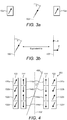
- Fig. 3a and 3b The largest magnetic asymmetry observed in axially magnetised permanent magnetic rings is usually a small angular error such that the magnet's axis is displaced from the rotational axis 102 by an angle of a few degrees as indicated in Fig. 3a .
- the angular error, ⁇ can be as much as 3 °.
- This error may be regarded as a small perturbation from the ideal axial magnetisation; in effect a transverse magnetic dipole moment 8 superimposed on the intended axial dipole moment 6 as illustrated in Fig 3b .
- transverse dipole first order
- asymmetries exist, for example quadrupole and hexapole asymmetries.
- the magnitude, or magnetic field strength, of the asymmetry usually decreases as the number of poles increases.
- the performance of scanning electron microscopes is highly susceptible to mechanical vibrations or stray magnetic fields emitted from turbomolecular pumps.
- the stray fields are known to directly interfere with the electron beam or with the instruments' electrical circuits.
- Magnetic bearing arrangements with two concentric arrays of axially polarized permanent ring magnets with the features of the preamble of claim 1 are described in DE102007017644 , US2340122 and EP2705263 . It is the intention of the present invention to overcome the above mentioned problems
- the present invention provides a magnetic bearing arrangement according to Claim 1.
- a single piece ring magnet with an even number of axially polarized zones is provided for the rotating element of the bearing arrangement instead of the array of separate ring magnets described above in the prior art.
- the axially polarized zones each act as separate magnets, or sub-ring magnets, and are formed during manufacture of the magnet along the axial length of the single piece magnet such that they are in mutual repulsion with each other; that is neighbouring sub-magnets in an array meet their nearest neighbouring sub-magnet in the array with the same magnetic pole (north-north, or south-south).
- the single piece magnet substantially reproduces the magnetic field of an array of an even number of magnets, but with reduced stray field effects.
- the single piece rotating magnet of the present invention overcomes the issues described above for a magnet array formed of four separate ring magnets because removal of the relative asymmetries between magnets created when manufacturing all the magnets separately. Asymmetries, and thus transverse fields, can arise due to slight variations in either the aligning field applied during the pressing stage, or errors in the sintering or finishing processes (grinding/milling the surfaces of the sintered magnets).
- any angular asymmetry from the axial magnetization (as in the angular error, ⁇ ) is equal along the whole length of the magnet for all of the axially polarized zones.
- the net transverse field about the rotational axis is zero.
- the advantage of producing a single piece ring magnet comprising an even number of axially polarized zones compared to the use of separate ring magnets in an array 12 as shown in figure 2 , is that there can be only one angular error, ⁇ , from the ideal geometric (rotational) axis 102.
- ⁇ angular error
- the angular error comes from either the compression, sintering or finishing stages of magnet production, every magnet produced will have its own errors.
- the net transverse dipole moment along a single piece magnet 122 will be zero (as shown by the line 400 in Figure 4 ).
- the magnet 122 is illustrated with 4 axially polarized zones, it may have any even number of axially polarized zones, for example 6, 8, 10 or 12, according to the requirements of the particular bearing arrangement. The important feature is that there must be an even number of axially polarized zones for there to be a zero net transverse dipole moment, and thus virtually no stray fields produced when the magnet is rotating in the bearing arrangement of a turbomolecular pump.
- the magnet 122 is produced following the stages described above. However in order to produce a plurality of axially polarized zones, once the single piece magnet has been compressed in the aligning field to the desired shape, sintered and finished it is advantageous to charge the magnet to produce each of the polarized zones 122a, 122b, 122c and 122d simultaneously. In order to do this the as yet uncharged zones (not shown) should each be surrounded by its own solenoid designed to axially polarize said zones. Ideally a solenoid is also placed into the internal bore of the magnet 122 so that each zone has its own solenoid pair charging it. The solenoids/solenoid pairs preferably create each axially polarized zone to be of the same magnetic strength.
- Figure 4 also illustrates the relative position of the stationary, non-rotating magnet 144 of the bearing arrangement 300, i.e. the non-rotating magnet 144 is surrounded concentrically by the magnet 122.
- the magnet 144 is formed from an array of separate, axially polarized ring magnet as in the prior bearing arrangement (shown in figure 2 ).
- the magnet 144 can, not in accordance with the invention, also be formed from a single piece magnet comprising an equal number of polarized zones (144a, 144b, 144c,and 144d) to that of the rotating magnet 122.
- a single piece magnet is also mechanically stronger, requires less manufacturing time, and is easier to handle than an array of separate magnets.
- turbomolecular pumps comprising the magnets of the present invention can be made more efficiently than previous devices.
- the axially polarized zones 122a-d and 144a-d also are orientated to provide a mutual repulsion between the magnets 122, 144 and therefore create an almost frictionless bearing 300.
- the bearing arrangement 300 is preferably used for the magnetic bearing of a high rotational speed machine, in particular in a turbomolecular pump to reduce stray fields in applications such as scanning electron microscopes.
Landscapes
- Engineering & Computer Science (AREA)
- General Engineering & Computer Science (AREA)
- Mechanical Engineering (AREA)
- Physics & Mathematics (AREA)
- Electromagnetism (AREA)
- Power Engineering (AREA)
- Magnetic Bearings And Hydrostatic Bearings (AREA)
- Non-Positive Displacement Air Blowers (AREA)
Description
- The present invention is directed to a magnet for a magnetic bearing arrangement, a bearing arrangement comprising said magnet, and a vacuum pump comprising said bearing arrangement. In particular the invention can be particularly useful in a magnetic bearing arrangement that reduces stray magnetic fields for a turbomolecular vacuum pump, although it is understood that the invention is not limited to this field and other applications will be understood by the skilled person.
- The present invention is described below with respect to a specific application. However, it is understood that the invention is not limited to turbomolecular vacuum pumps.
- Turbomolecular pumps are often employed as a component of the vacuum system used to evacuate devices such as scanning electron microscopes (SEMs) and lithography devices.
- It is common for said turbomolecular pumps to comprise an oil free, passive permanent magnetic bearing arrangement, located in the high vacuum end of the pump, to provide a substantially friction free, dry bearing arrangement free of lubricating materials that might otherwise cause contamination in the evacuated volume.
- As described in
EP2705263 , known arrangements of passive permanent magnetic bearings employ a plurality of individual axially stacked ring magnets. Examples of such arrangements are shown inFigures 1 and 2 . -
Figure 1 illustrates a section of atypical turbomolecular pump 200 comprising a series ofrotor blades 106 extending outwardly from arotor shaft 108. A passivemagnetic bearing arrangement shaft 108. Thebearing arrangement permanent magnet rings 100 fixed to the pump housing surrounded concentrically by a series of three individualpermanent magnet rings 110 which are fixed to, and rotate with, therotor arrangement axis 102. - A cross section of a further example of a passive permanent
magnetic bearing arrangement 10 for a turbomolecular pump (not shown) is illustrated in more detail inFig 2 . In this example thebearing arrangement 10 comprises anarray 12 of four outer rotatingpermanent magnet rings array 14 of four inner non-rotating permanentmagnetic rings array 12 surrounds the inner, static,array 14 in a concentric manner. The magnets are all formed of rare earth magnetic material, such as samarium-cobalt. Theouter array 12 is attached to the rotor of a turbomolecular pump (not shown) with thestatic array 14 attached to the stator of said pump. For reasons of mechanical strength and practical construction, it is normal for the outer array of rings to form the rotating part of the bearing arrangement and the inner rings to form the stationary part. - In this example the magnetisation, (that is, the polarization), of the
magnetic rings 12a to12d and 14a to14d in eacharray rotation 102 of the pump rotor (not shown). The direction of magnetisation (polarization) has been indicated by the arrows, with the head of each arrow indicating the north pole. - The magnets are arranged within each array such that they are in mutual repulsion with each other; that is proximate magnets in an array meet their nearest neighbouring magnet in the same array with the same pole (
e.g. magnets magnetic rings - The
magnets 12a to12d and 14a to14d in eacharray arrangement 10 are orientated to provide a mutual repulsion between thearrays - A great many other configurations are possible, using different numbers of rings, with axial or radial magnetisation, and arranged for either repulsive or attractive forces between rotor and stator. Although a variety of configurations are possible, they all perform optimally when the direction of magnetisation in the rings is perfectly symmetrical with respect to their
rotational axis 102. - The magnetisation in the
rings 12a to 12d of therotating array 12 is shown inFig. 2 as perfectly symmetrical with respect to their geometric (rotational)axis 102. However, in reality, the axial magnetisation of eachmagnetic ring 12a to12d (and, similarly, formagnets 14a to 14d) is imperfect due to the practical limitations of their manufacturing process. - Although the production of magnets is well known to those skilled in the art, in order to illustrate how the imperfections in the process arise and cause problems in turbomolecular pumps, a simplified version will be described herein.
- The most common method of producing magnets is via powder metallurgy. The process starts by forming a fine powder which is then compacted and sintered together, before being charged, or magnetized.
- The fine powder, which is formed by several steps, is provided with a specific particle size to contain material with one preferred magnetic orientation.
- Following the formation of the powder it is compacted to the desired shape. The two well-known techniques used for this process are axial/transverse pressing and isostatic pressing. Both methods essentially involve aligning and fixing the particles so all the magnetic regions in the finished magnet are pointing in a single direction.
- In axial/transverse pressing, the powder is placed into a rigid cavity shaped to match the shape of the final magnet and then compressed with a pressing tool. Before the compression occurs, an aligning magnetic field is applied to the powder to ensure that all the particles are aligned in the same direction. The act of compression fixes, or "freezes-in" this alignment.
- Isostatic pressing is where a flexible container is filled with the powder, the container is then sealed, and an aligning field applied. The container is then isostatically pressed using a hydraulic fluid (e.g. water), thus, pressure is applied to the outside of the sealed container, compacting it equally on all sides. By isostatic pressing it is both possible to make large magnets and, because the compacting pressure is applied equally on all sides ensuring the powder remains in relatively good alignment, with relatively high magnetic energy.
- The pressed parts are then sintered in a vacuum sintering furnace, with the temperature and atmosphere around the magnet being specified dependent on the type and grade of magnet being produced. Rare earth materials are heated to a sintering temperature and allowed to densify over time. The SmCo magnets used in the above examples have the additional requirement of a solutionising heat treatment after sintering.
- When the sintering process is complete the magnets have rough surfaces and only approximate dimensions so require further treatment by, for example, grinding of the internal and external surfaces to produce the final finish. At this point they still exhibit no external magnetic field.
- Following the finishing process, the magnet then requires magnetizing to produce an external magnetic field. This can be accomplished in a solenoid comprising a hollow cylinder into which various magnet sizes and shapes can be placed, or with other devices designed to impart unique magnetic patterns.
- Thus when each individual magnet in the array is made, they can each pick up minor variations in the orientation of the direction of magnetic field. Therefore the individual ring magnets have slight imperfections with respect to each other and so the axial alignment of the polarizations in an array with respect to the
rotational axis 102 will also be imperfect (asymmetric) with respect to each other. - This is illustrated in
Fig. 3a and 3b . The largest magnetic asymmetry observed in axially magnetised permanent magnetic rings is usually a small angular error such that the magnet's axis is displaced from therotational axis 102 by an angle of a few degrees as indicated inFig. 3a . Depending on the quality, or grade, of the magnet the angular error, θ, can be as much as 3 °. This error may be regarded as a small perturbation from the ideal axial magnetisation; in effect a transversemagnetic dipole moment 8 superimposed on the intendedaxial dipole moment 6 as illustrated inFig 3b . - In addition to the transverse dipole (first order) asymmetry, higher order asymmetries exist, for example quadrupole and hexapole asymmetries. The magnitude, or magnetic field strength, of the asymmetry usually decreases as the number of poles increases.
- Where these small asymmetries occur in any of the
rings 12a to 12d of the rotatingmagnet array 12, a time varying magnetic field is generated (the magnetic field is constant for thestatic magnets 14a to 14d). These 2, 4 and 6 pole asymmetries generate time varying magnetic fields at frequencies of 1, 2 and 3 times the rotational speed of the pump rotor respectively. - The performance of scanning electron microscopes is highly susceptible to mechanical vibrations or stray magnetic fields emitted from turbomolecular pumps. The stray fields are known to directly interfere with the electron beam or with the instruments' electrical circuits.
- One known way to overcome the above described problems of stray first and second order magnetic fields, as described in
EP2705263 , is by assembling the rotating magnet array for a permanent magnet bearing arrangement by a method which effectively cancels out the stray fields of each individual magnet. This is achieved by first measuring/characterising the size and phase (vectors) of at least the first and second order transverse stray magnetic fields of a plurality of magnets, namely the transverse dipole and quadrupole stray fields. Then, for at least four ring magnets individually in relation to a reference point on said ring magnets, calculating the relative angular orientation and relative magnetic polarity direction of each of said at least 4 magnets within the array such that, when the array is assembled, it will provide the minimum time-varying magnetic field. This is the optimum relative orientation of the magnets at which all of the stray fields for each of the magnets are substantially cancelled out. - However, one problem with the above described method is that many magnets have to be characterised in order to find acceptable combinations of magnets for a pump. In other words, in order to find a combination of four ring magnets for which the stray magnetic fields can be substantially cancelled out the initial characterisation of more than four magnets is needed. Multipole bearing arrangements comprising single piece elongate permanent ring magnets with an even number of axially polarized zones are disclosed in
US2004/227421 ;US2340122 andJPS6159964 - Magnetic bearing arrangements with two concentric arrays of axially polarized permanent ring magnets with the features of the preamble of
claim 1 are described inDE102007017644 ,US2340122 andEP2705263 . It is the intention of the present invention to overcome the above mentioned problems - In a first aspect the present invention provides a magnetic bearing arrangement according to
Claim 1. - Thus a single piece ring magnet with an even number of axially polarized zones is provided for the rotating element of the bearing arrangement instead of the array of separate ring magnets described above in the prior art. The axially polarized zones each act as separate magnets, or sub-ring magnets, and are formed during manufacture of the magnet along the axial length of the single piece magnet such that they are in mutual repulsion with each other; that is neighbouring sub-magnets in an array meet their nearest neighbouring sub-magnet in the array with the same magnetic pole (north-north, or south-south). The single piece magnet substantially reproduces the magnetic field of an array of an even number of magnets, but with reduced stray field effects.
- The single piece rotating magnet of the present invention overcomes the issues described above for a magnet array formed of four separate ring magnets because removal of the relative asymmetries between magnets created when manufacturing all the magnets separately. Asymmetries, and thus transverse fields, can arise due to slight variations in either the aligning field applied during the pressing stage, or errors in the sintering or finishing processes (grinding/milling the surfaces of the sintered magnets). By providing a one piece magnet any angular asymmetry from the axial magnetization (as in the angular error, θ) is equal along the whole length of the magnet for all of the axially polarized zones. Thus, assuming all of the axially polarized zones are of equal magnetic strength, the net transverse field about the rotational axis is zero.
- Further aspects of the invention are set out in the claims.
- In order that the present invention may be well understood embodiments thereof, which are given by way of example only, will now be described with reference to the accompanying drawings, in which:
-
Fig. 1 is a cross section of a turbomolecular pump. -
Fig. 2 is a cross sectional illustration of a passive magnetic bearing arrangement for a turbomolecular pump. -
Fig. 3a is an illustration of the asymmetric magnetisation of a permanent ring magnet. -
Fig. 3b is an illustration of the asymmetric magnetisation of a permanent ring magnet. -
Fig, 4 is an illustration of a magnetic bearing arrangement comprising the magnet according to the invention -
Figure 4 illustrates amagnetic bearing arrangement 300 comprising thering magnet 122 according to the present invention. Thering magnet 122 is a single piece cylindrical tubular magnet formed of a magnetic material, for example samarium-cobalt. When in use in thebearing arrangement 300 themagnet 122 rotates with the rotor of a turbomolecular pump (not shown) about theaxis 102. Theaxis 102 passes parallel to and centrally through the bore of themagnet 122 as shown. The magnet illustrated has four axiallypolarized zones example zones - As stated above, the advantage of producing a single piece ring magnet comprising an even number of axially polarized zones, compared to the use of separate ring magnets in an
array 12 as shown infigure 2 , is that there can be only one angular error, θ, from the ideal geometric (rotational)axis 102. As the angular error comes from either the compression, sintering or finishing stages of magnet production, every magnet produced will have its own errors. However, it is only possible to obtain a single, uniform angular error, θ, along the whole axial length of a single piece magnet. Thus, assuming that thepolarized zones single piece magnet 122 will be zero (as shown by theline 400 inFigure 4 ). Although themagnet 122 is illustrated with 4 axially polarized zones, it may have any even number of axially polarized zones, for example 6, 8, 10 or 12, according to the requirements of the particular bearing arrangement. The important feature is that there must be an even number of axially polarized zones for there to be a zero net transverse dipole moment, and thus virtually no stray fields produced when the magnet is rotating in the bearing arrangement of a turbomolecular pump. - The
magnet 122 is produced following the stages described above. However in order to produce a plurality of axially polarized zones, once the single piece magnet has been compressed in the aligning field to the desired shape, sintered and finished it is advantageous to charge the magnet to produce each of thepolarized zones magnet 122 so that each zone has its own solenoid pair charging it. The solenoids/solenoid pairs preferably create each axially polarized zone to be of the same magnetic strength. -
Figure 4 also illustrates the relative position of the stationary,non-rotating magnet 144 of thebearing arrangement 300, i.e. thenon-rotating magnet 144 is surrounded concentrically by themagnet 122. In accordance with the invention themagnet 144 is formed from an array of separate, axially polarized ring magnet as in the prior bearing arrangement (shown infigure 2 ). Themagnet 144 can, not in accordance with the invention, also be formed from a single piece magnet comprising an equal number of polarized zones (144a, 144b, 144c,and 144d) to that of therotating magnet 122. In addition to the reduced stray magnetic fields, a single piece magnet is also mechanically stronger, requires less manufacturing time, and is easier to handle than an array of separate magnets. Thus turbomolecular pumps comprising the magnets of the present invention can be made more efficiently than previous devices. - The axially
polarized zones 122a-d and 144a-d also are orientated to provide a mutual repulsion between themagnets frictionless bearing 300. - The
bearing arrangement 300 is preferably used for the magnetic bearing of a high rotational speed machine, in particular in a turbomolecular pump to reduce stray fields in applications such as scanning electron microscopes.
Claims (4)
- A magnetic bearing arrangement (400) for rotating machinery comprising:a rotating magnet (122); anda non-rotating magnet (144),wherein the non-rotating magnet (144) comprises an array of axially polarized permanent ring magnets with axially neighbouring rings in mutual repulsion to each other; andcharacterised in that the rotating magnet (122) comprises a single piece elongate permanent ring magnet which, in use, has an axis of rotation (102) parallel with, and centrally through the bore of the ring magnet, wherein the magnet comprises an even number of axially polarized zones (122a, 122b, 122c, 122d) between the axial ends of the magnet, with axially neighbouring polarized zones in mutual repulsion to each other said rotating magnet (122) concentrically surrounding the non-rotating magnet (144), and wherein the axially polarized zones (122a, 122b, 122c, 122d) on the rotating magnet and the axially polarized ring magnets of the non-rotating magnet array are orientated to provide a mutual repulsion between the rotating magnet and non-rotating magnet array.
- A magnetic bearing arrangement according to claim 1, wherein the rotating single piece ring magnet (122) comprising at least four axially polarized zones (122a, 122b, 122c, and 122d).
- A high speed rotational device comprising a bearing arrangement according to Claims 1 and 2.
- A turbomolecular pump comprising a bearing arrangement according to Claims 1 and 2.
Applications Claiming Priority (2)
| Application Number | Priority Date | Filing Date | Title |
|---|---|---|---|
| GBGB1408899.1A GB201408899D0 (en) | 2014-05-20 | 2014-05-20 | Magnetic bearing |
| PCT/GB2015/051309 WO2015177504A1 (en) | 2014-05-20 | 2015-05-05 | Elongated permanent ring magnet with a plurality of axially directed magnetized zones and magnetic bearing with such a ring magnet |
Publications (2)
| Publication Number | Publication Date |
|---|---|
| EP3146222A1 EP3146222A1 (en) | 2017-03-29 |
| EP3146222B1 true EP3146222B1 (en) | 2018-04-11 |
Family
ID=51135110
Family Applications (1)
| Application Number | Title | Priority Date | Filing Date |
|---|---|---|---|
| EP15720220.1A Active EP3146222B1 (en) | 2014-05-20 | 2015-05-05 | Elongated permanent ring magnet with a plurality of axially directed magnetized zones and magnetic bearing with such a ring magnet |
Country Status (7)
| Country | Link |
|---|---|
| US (1) | US10359047B2 (en) |
| EP (1) | EP3146222B1 (en) |
| JP (1) | JP6613248B2 (en) |
| CN (1) | CN106460925B (en) |
| CA (1) | CA2945204A1 (en) |
| GB (1) | GB201408899D0 (en) |
| WO (1) | WO2015177504A1 (en) |
Cited By (1)
| Publication number | Priority date | Publication date | Assignee | Title |
|---|---|---|---|---|
| WO2023135411A1 (en) | 2022-01-13 | 2023-07-20 | Edwards Limited | A pump and a method of reducing a stray magnetic field of the pump |
Families Citing this family (3)
| Publication number | Priority date | Publication date | Assignee | Title |
|---|---|---|---|---|
| EP3196471B1 (en) * | 2016-01-19 | 2023-08-23 | Pfeiffer Vacuum Gmbh | Vacuum pump |
| EP3385961B1 (en) * | 2017-04-05 | 2021-09-01 | Pfeiffer Vacuum Gmbh | Monolithic permanent magnet |
| GB2630915A (en) * | 2023-06-08 | 2024-12-18 | Edwards Ltd | Vacuum pump passive magnetic bearings |
Family Cites Families (19)
| Publication number | Priority date | Publication date | Assignee | Title |
|---|---|---|---|---|
| US2340122A (en) * | 1942-06-30 | 1944-01-25 | Gen Electric | Magnet suspension |
| DE2103737C3 (en) * | 1971-01-27 | 1978-08-24 | Max 5060 Bergisch Gladbach Baermann | Magnetic axial bearing for electricity meters |
| JPS6159964U (en) * | 1984-09-27 | 1986-04-22 | ||
| US4939120A (en) * | 1988-08-01 | 1990-07-03 | Cornell Research Foundation, Inc. | Superconducting rotating assembly |
| JPH04219493A (en) * | 1990-08-10 | 1992-08-10 | Ebara Corp | Turbo-molecular pump |
| JPH11325075A (en) | 1998-05-13 | 1999-11-26 | Sankyo Seiki Mfg Co Ltd | Magnetic bearing |
| JP2002122137A (en) * | 2000-10-10 | 2002-04-26 | Sankyo Seiki Mfg Co Ltd | Bearing device |
| US6448679B1 (en) * | 2000-12-14 | 2002-09-10 | Joseph Imlach | Passive magnetic support and damping system |
| JP4271030B2 (en) * | 2001-08-24 | 2009-06-03 | ベルリン ハート ゲーエムベーハー | Hard magnetic object and method for adjusting direction and position of magnetic vector |
| US20040189123A1 (en) * | 2001-08-24 | 2004-09-30 | Peter Nusser | Magnetically hard object and method for adjusting the direction and position of a magnetic vector |
| DE10321925B4 (en) * | 2003-05-15 | 2008-10-02 | Vacuumschmelze Gmbh & Co. Kg | Radial magnetic bearing, method for assembling a magnetic bearing and rotary machine with a radial magnetic bearing |
| TWI220327B (en) * | 2003-05-16 | 2004-08-11 | Ind Tech Res Inst | Magnetic levitation bearing structure |
| JP2008118002A (en) * | 2006-11-07 | 2008-05-22 | Ntn Corp | Magnetization coil of permanent magnet and its manufacturing process |
| DE102007017644B4 (en) * | 2007-04-13 | 2020-01-30 | Minebea Mitsumi Inc. | hybrid bearings |
| US20090039995A1 (en) * | 2007-07-09 | 2009-02-12 | Ronald Kipp | Permanent Magnet or Permanent Magnet Array having Uniform Flux Density |
| IT1390944B1 (en) * | 2008-08-04 | 2011-10-27 | Scuola Superiore Di Studi Universitari E Di Perfez | PERMANENT MAGNET ACTUATOR FOR ADAPTIVE TYPE IMPLEMENTATION |
| JP2011029215A (en) * | 2009-07-21 | 2011-02-10 | Nichia Corp | Cylindrical bond magnet and method of manufacturing the same |
| GB2490863B (en) * | 2011-05-06 | 2018-04-18 | Edwards Ltd | Magnetic bearing assembly |
| DE102012216450A1 (en) * | 2012-09-14 | 2014-03-20 | Pfeiffer Vacuum Gmbh | Method for centering a vacuum pump or a rotation unit for a vacuum pump |
-
2014
- 2014-05-20 GB GBGB1408899.1A patent/GB201408899D0/en not_active Ceased
-
2015
- 2015-05-05 US US15/311,887 patent/US10359047B2/en active Active
- 2015-05-05 JP JP2016568545A patent/JP6613248B2/en active Active
- 2015-05-05 WO PCT/GB2015/051309 patent/WO2015177504A1/en not_active Ceased
- 2015-05-05 CN CN201580025718.9A patent/CN106460925B/en active Active
- 2015-05-05 CA CA2945204A patent/CA2945204A1/en not_active Abandoned
- 2015-05-05 EP EP15720220.1A patent/EP3146222B1/en active Active
Cited By (1)
| Publication number | Priority date | Publication date | Assignee | Title |
|---|---|---|---|---|
| WO2023135411A1 (en) | 2022-01-13 | 2023-07-20 | Edwards Limited | A pump and a method of reducing a stray magnetic field of the pump |
Also Published As
| Publication number | Publication date |
|---|---|
| JP6613248B2 (en) | 2019-11-27 |
| CA2945204A1 (en) | 2015-11-26 |
| WO2015177504A1 (en) | 2015-11-26 |
| CN106460925A (en) | 2017-02-22 |
| US20170089351A1 (en) | 2017-03-30 |
| GB201408899D0 (en) | 2014-07-02 |
| US10359047B2 (en) | 2019-07-23 |
| EP3146222A1 (en) | 2017-03-29 |
| CN106460925B (en) | 2019-12-06 |
| JP2017517887A (en) | 2017-06-29 |
Similar Documents
| Publication | Publication Date | Title |
|---|---|---|
| US10600539B2 (en) | Contoured-field magnets | |
| EP3146222B1 (en) | Elongated permanent ring magnet with a plurality of axially directed magnetized zones and magnetic bearing with such a ring magnet | |
| JP2018523127A (en) | Statically balanced mechanism using a Halbach cylinder | |
| JP2006086319A (en) | Ring-type sintered magnet | |
| US20190238016A1 (en) | Rotor for an electric machine, electric machine with the rotor and to method for producing the rotor | |
| US20080051622A1 (en) | Hard magnetic object and method for adjusting the direction and position of a magnetic vector | |
| KR102410836B1 (en) | Dipole ring magnetic field generator | |
| WO2019008372A1 (en) | Magnetic bearing | |
| US20030160674A1 (en) | Rotor, rotating machine and magnetic field generating apparatus | |
| AU2016250494B2 (en) | Electric current generating turbine | |
| CN209001684U (en) | The block and rotating electric machine of stator, stator | |
| JP6611780B2 (en) | Monolithic permanent magnet | |
| KR101247283B1 (en) | Rotor assembly and the manufacturing method for the same | |
| CN213471601U (en) | An Anisotropic Permanent Magnet Radial Multistage Magnetic Ring Magnetic Circuit Die | |
| CN207835191U (en) | A kind of rotor using Halbach magnet ring | |
| CN205609346U (en) | Magnetism base manufacture equipment | |
| AU2007342082B2 (en) | Permanent magnet having improved field quality and apparatus employing the same | |
| Xu et al. | Design and analysis of Lorentz force-type magnetic bearing based on high precision and low power consumption | |
| CN207353936U (en) | Magnet ring, rotor and motor | |
| RU2305357C1 (en) | Homogeneous magnetic field inductor | |
| Choi et al. | Design of permanent magnet systems using finite element analysis | |
| Biggs et al. | Magnetization, Geometry, and Segmentation Analysis of Nested Halbach Cylinders for Optimizing the Interactive Torque | |
| CN121311692A (en) | Vacuum pump and permanent magnet bearing assembly for vacuum pump | |
| Martinek et al. | Optimizing magnetic effects through shaped field magnets | |
| CN107045931A (en) | Magnetic base manufacturing equipment and magnetic base manufacture method |
Legal Events
| Date | Code | Title | Description |
|---|---|---|---|
| STAA | Information on the status of an ep patent application or granted ep patent |
Free format text: STATUS: THE INTERNATIONAL PUBLICATION HAS BEEN MADE |
|
| PUAI | Public reference made under article 153(3) epc to a published international application that has entered the european phase |
Free format text: ORIGINAL CODE: 0009012 |
|
| STAA | Information on the status of an ep patent application or granted ep patent |
Free format text: STATUS: REQUEST FOR EXAMINATION WAS MADE |
|
| 17P | Request for examination filed |
Effective date: 20161115 |
|
| AK | Designated contracting states |
Kind code of ref document: A1 Designated state(s): AL AT BE BG CH CY CZ DE DK EE ES FI FR GB GR HR HU IE IS IT LI LT LU LV MC MK MT NL NO PL PT RO RS SE SI SK SM TR |
|
| AX | Request for extension of the european patent |
Extension state: BA ME |
|
| DAV | Request for validation of the european patent (deleted) | ||
| DAX | Request for extension of the european patent (deleted) | ||
| RIC1 | Information provided on ipc code assigned before grant |
Ipc: F04D 19/04 20060101ALN20171019BHEP Ipc: H01F 7/02 20060101ALN20171019BHEP Ipc: F16C 32/04 20060101AFI20171019BHEP Ipc: F04D 29/058 20060101ALN20171019BHEP |
|
| GRAP | Despatch of communication of intention to grant a patent |
Free format text: ORIGINAL CODE: EPIDOSNIGR1 |
|
| STAA | Information on the status of an ep patent application or granted ep patent |
Free format text: STATUS: GRANT OF PATENT IS INTENDED |
|
| INTG | Intention to grant announced |
Effective date: 20171128 |
|
| GRAS | Grant fee paid |
Free format text: ORIGINAL CODE: EPIDOSNIGR3 |
|
| GRAA | (expected) grant |
Free format text: ORIGINAL CODE: 0009210 |
|
| STAA | Information on the status of an ep patent application or granted ep patent |
Free format text: STATUS: THE PATENT HAS BEEN GRANTED |
|
| AK | Designated contracting states |
Kind code of ref document: B1 Designated state(s): AL AT BE BG CH CY CZ DE DK EE ES FI FR GB GR HR HU IE IS IT LI LT LU LV MC MK MT NL NO PL PT RO RS SE SI SK SM TR |
|
| REG | Reference to a national code |
Ref country code: GB Ref legal event code: FG4D |
|
| REG | Reference to a national code |
Ref country code: CH Ref legal event code: EP |
|
| REG | Reference to a national code |
Ref country code: AT Ref legal event code: REF Ref document number: 988353 Country of ref document: AT Kind code of ref document: T Effective date: 20180415 |
|
| REG | Reference to a national code |
Ref country code: IE Ref legal event code: FG4D |
|
| REG | Reference to a national code |
Ref country code: DE Ref legal event code: R096 Ref document number: 602015009890 Country of ref document: DE |
|
| REG | Reference to a national code |
Ref country code: FR Ref legal event code: PLFP Year of fee payment: 4 |
|
| REG | Reference to a national code |
Ref country code: NL Ref legal event code: MP Effective date: 20180411 |
|
| REG | Reference to a national code |
Ref country code: LT Ref legal event code: MG4D |
|
| PG25 | Lapsed in a contracting state [announced via postgrant information from national office to epo] |
Ref country code: NL Free format text: LAPSE BECAUSE OF FAILURE TO SUBMIT A TRANSLATION OF THE DESCRIPTION OR TO PAY THE FEE WITHIN THE PRESCRIBED TIME-LIMIT Effective date: 20180411 |
|
| PG25 | Lapsed in a contracting state [announced via postgrant information from national office to epo] |
Ref country code: PL Free format text: LAPSE BECAUSE OF FAILURE TO SUBMIT A TRANSLATION OF THE DESCRIPTION OR TO PAY THE FEE WITHIN THE PRESCRIBED TIME-LIMIT Effective date: 20180411 Ref country code: FI Free format text: LAPSE BECAUSE OF FAILURE TO SUBMIT A TRANSLATION OF THE DESCRIPTION OR TO PAY THE FEE WITHIN THE PRESCRIBED TIME-LIMIT Effective date: 20180411 Ref country code: LT Free format text: LAPSE BECAUSE OF FAILURE TO SUBMIT A TRANSLATION OF THE DESCRIPTION OR TO PAY THE FEE WITHIN THE PRESCRIBED TIME-LIMIT Effective date: 20180411 Ref country code: BG Free format text: LAPSE BECAUSE OF FAILURE TO SUBMIT A TRANSLATION OF THE DESCRIPTION OR TO PAY THE FEE WITHIN THE PRESCRIBED TIME-LIMIT Effective date: 20180711 Ref country code: AL Free format text: LAPSE BECAUSE OF FAILURE TO SUBMIT A TRANSLATION OF THE DESCRIPTION OR TO PAY THE FEE WITHIN THE PRESCRIBED TIME-LIMIT Effective date: 20180411 Ref country code: ES Free format text: LAPSE BECAUSE OF FAILURE TO SUBMIT A TRANSLATION OF THE DESCRIPTION OR TO PAY THE FEE WITHIN THE PRESCRIBED TIME-LIMIT Effective date: 20180411 Ref country code: SE Free format text: LAPSE BECAUSE OF FAILURE TO SUBMIT A TRANSLATION OF THE DESCRIPTION OR TO PAY THE FEE WITHIN THE PRESCRIBED TIME-LIMIT Effective date: 20180411 Ref country code: NO Free format text: LAPSE BECAUSE OF FAILURE TO SUBMIT A TRANSLATION OF THE DESCRIPTION OR TO PAY THE FEE WITHIN THE PRESCRIBED TIME-LIMIT Effective date: 20180711 |
|
| PG25 | Lapsed in a contracting state [announced via postgrant information from national office to epo] |
Ref country code: LV Free format text: LAPSE BECAUSE OF FAILURE TO SUBMIT A TRANSLATION OF THE DESCRIPTION OR TO PAY THE FEE WITHIN THE PRESCRIBED TIME-LIMIT Effective date: 20180411 Ref country code: HR Free format text: LAPSE BECAUSE OF FAILURE TO SUBMIT A TRANSLATION OF THE DESCRIPTION OR TO PAY THE FEE WITHIN THE PRESCRIBED TIME-LIMIT Effective date: 20180411 Ref country code: GR Free format text: LAPSE BECAUSE OF FAILURE TO SUBMIT A TRANSLATION OF THE DESCRIPTION OR TO PAY THE FEE WITHIN THE PRESCRIBED TIME-LIMIT Effective date: 20180712 Ref country code: RS Free format text: LAPSE BECAUSE OF FAILURE TO SUBMIT A TRANSLATION OF THE DESCRIPTION OR TO PAY THE FEE WITHIN THE PRESCRIBED TIME-LIMIT Effective date: 20180411 |
|
| REG | Reference to a national code |
Ref country code: CH Ref legal event code: PL |
|
| REG | Reference to a national code |
Ref country code: AT Ref legal event code: MK05 Ref document number: 988353 Country of ref document: AT Kind code of ref document: T Effective date: 20180411 |
|
| PG25 | Lapsed in a contracting state [announced via postgrant information from national office to epo] |
Ref country code: PT Free format text: LAPSE BECAUSE OF FAILURE TO SUBMIT A TRANSLATION OF THE DESCRIPTION OR TO PAY THE FEE WITHIN THE PRESCRIBED TIME-LIMIT Effective date: 20180813 |
|
| REG | Reference to a national code |
Ref country code: DE Ref legal event code: R097 Ref document number: 602015009890 Country of ref document: DE |
|
| REG | Reference to a national code |
Ref country code: BE Ref legal event code: MM Effective date: 20180531 |
|
| PG25 | Lapsed in a contracting state [announced via postgrant information from national office to epo] |
Ref country code: AT Free format text: LAPSE BECAUSE OF FAILURE TO SUBMIT A TRANSLATION OF THE DESCRIPTION OR TO PAY THE FEE WITHIN THE PRESCRIBED TIME-LIMIT Effective date: 20180411 Ref country code: MC Free format text: LAPSE BECAUSE OF FAILURE TO SUBMIT A TRANSLATION OF THE DESCRIPTION OR TO PAY THE FEE WITHIN THE PRESCRIBED TIME-LIMIT Effective date: 20180411 Ref country code: SK Free format text: LAPSE BECAUSE OF FAILURE TO SUBMIT A TRANSLATION OF THE DESCRIPTION OR TO PAY THE FEE WITHIN THE PRESCRIBED TIME-LIMIT Effective date: 20180411 Ref country code: RO Free format text: LAPSE BECAUSE OF FAILURE TO SUBMIT A TRANSLATION OF THE DESCRIPTION OR TO PAY THE FEE WITHIN THE PRESCRIBED TIME-LIMIT Effective date: 20180411 Ref country code: CZ Free format text: LAPSE BECAUSE OF FAILURE TO SUBMIT A TRANSLATION OF THE DESCRIPTION OR TO PAY THE FEE WITHIN THE PRESCRIBED TIME-LIMIT Effective date: 20180411 Ref country code: EE Free format text: LAPSE BECAUSE OF FAILURE TO SUBMIT A TRANSLATION OF THE DESCRIPTION OR TO PAY THE FEE WITHIN THE PRESCRIBED TIME-LIMIT Effective date: 20180411 Ref country code: DK Free format text: LAPSE BECAUSE OF FAILURE TO SUBMIT A TRANSLATION OF THE DESCRIPTION OR TO PAY THE FEE WITHIN THE PRESCRIBED TIME-LIMIT Effective date: 20180411 |
|
| PLBE | No opposition filed within time limit |
Free format text: ORIGINAL CODE: 0009261 |
|
| STAA | Information on the status of an ep patent application or granted ep patent |
Free format text: STATUS: NO OPPOSITION FILED WITHIN TIME LIMIT |
|
| REG | Reference to a national code |
Ref country code: IE Ref legal event code: MM4A |
|
| PG25 | Lapsed in a contracting state [announced via postgrant information from national office to epo] |
Ref country code: CH Free format text: LAPSE BECAUSE OF NON-PAYMENT OF DUE FEES Effective date: 20180531 Ref country code: LI Free format text: LAPSE BECAUSE OF NON-PAYMENT OF DUE FEES Effective date: 20180531 Ref country code: SM Free format text: LAPSE BECAUSE OF FAILURE TO SUBMIT A TRANSLATION OF THE DESCRIPTION OR TO PAY THE FEE WITHIN THE PRESCRIBED TIME-LIMIT Effective date: 20180411 |
|
| 26N | No opposition filed |
Effective date: 20190114 |
|
| PG25 | Lapsed in a contracting state [announced via postgrant information from national office to epo] |
Ref country code: LU Free format text: LAPSE BECAUSE OF NON-PAYMENT OF DUE FEES Effective date: 20180505 |
|
| PG25 | Lapsed in a contracting state [announced via postgrant information from national office to epo] |
Ref country code: IE Free format text: LAPSE BECAUSE OF NON-PAYMENT OF DUE FEES Effective date: 20180505 |
|
| PG25 | Lapsed in a contracting state [announced via postgrant information from national office to epo] |
Ref country code: SI Free format text: LAPSE BECAUSE OF FAILURE TO SUBMIT A TRANSLATION OF THE DESCRIPTION OR TO PAY THE FEE WITHIN THE PRESCRIBED TIME-LIMIT Effective date: 20180411 Ref country code: BE Free format text: LAPSE BECAUSE OF NON-PAYMENT OF DUE FEES Effective date: 20180531 |
|
| PG25 | Lapsed in a contracting state [announced via postgrant information from national office to epo] |
Ref country code: MT Free format text: LAPSE BECAUSE OF NON-PAYMENT OF DUE FEES Effective date: 20180505 |
|
| PG25 | Lapsed in a contracting state [announced via postgrant information from national office to epo] |
Ref country code: TR Free format text: LAPSE BECAUSE OF FAILURE TO SUBMIT A TRANSLATION OF THE DESCRIPTION OR TO PAY THE FEE WITHIN THE PRESCRIBED TIME-LIMIT Effective date: 20180411 |
|
| PG25 | Lapsed in a contracting state [announced via postgrant information from national office to epo] |
Ref country code: MK Free format text: LAPSE BECAUSE OF NON-PAYMENT OF DUE FEES Effective date: 20180411 Ref country code: HU Free format text: LAPSE BECAUSE OF FAILURE TO SUBMIT A TRANSLATION OF THE DESCRIPTION OR TO PAY THE FEE WITHIN THE PRESCRIBED TIME-LIMIT; INVALID AB INITIO Effective date: 20150505 Ref country code: CY Free format text: LAPSE BECAUSE OF FAILURE TO SUBMIT A TRANSLATION OF THE DESCRIPTION OR TO PAY THE FEE WITHIN THE PRESCRIBED TIME-LIMIT Effective date: 20180411 |
|
| PG25 | Lapsed in a contracting state [announced via postgrant information from national office to epo] |
Ref country code: IS Free format text: LAPSE BECAUSE OF FAILURE TO SUBMIT A TRANSLATION OF THE DESCRIPTION OR TO PAY THE FEE WITHIN THE PRESCRIBED TIME-LIMIT Effective date: 20180811 |
|
| REG | Reference to a national code |
Ref country code: DE Ref legal event code: R082 Ref document number: 602015009890 Country of ref document: DE Representative=s name: FLEUCHAUS & GALLO PARTNERSCHAFT MBB - PATENT- , DE Ref country code: DE Ref legal event code: R082 Ref document number: 602015009890 Country of ref document: DE Representative=s name: FLEUCHAUS & GALLO PARTNERSCHAFT MBB PATENTANWA, DE |
|
| P01 | Opt-out of the competence of the unified patent court (upc) registered |
Effective date: 20230503 |
|
| PGFP | Annual fee paid to national office [announced via postgrant information from national office to epo] |
Ref country code: DE Payment date: 20250529 Year of fee payment: 11 |
|
| PGFP | Annual fee paid to national office [announced via postgrant information from national office to epo] |
Ref country code: GB Payment date: 20250527 Year of fee payment: 11 |
|
| PGFP | Annual fee paid to national office [announced via postgrant information from national office to epo] |
Ref country code: IT Payment date: 20250521 Year of fee payment: 11 |
|
| PGFP | Annual fee paid to national office [announced via postgrant information from national office to epo] |
Ref country code: FR Payment date: 20250526 Year of fee payment: 11 |