EP3145769B1 - Elektropneumatische bremssteuereinrichtung mit automatischer entlüftung der federspeicherbremse bei stromausfall - Google Patents
Elektropneumatische bremssteuereinrichtung mit automatischer entlüftung der federspeicherbremse bei stromausfall Download PDFInfo
- Publication number
- EP3145769B1 EP3145769B1 EP15719463.0A EP15719463A EP3145769B1 EP 3145769 B1 EP3145769 B1 EP 3145769B1 EP 15719463 A EP15719463 A EP 15719463A EP 3145769 B1 EP3145769 B1 EP 3145769B1
- Authority
- EP
- European Patent Office
- Prior art keywords
- brake
- compressed air
- valve
- control
- pressure
- Prior art date
- Legal status (The legal status is an assumption and is not a legal conclusion. Google has not performed a legal analysis and makes no representation as to the accuracy of the status listed.)
- Active
Links
Images

Classifications
-
- B—PERFORMING OPERATIONS; TRANSPORTING
- B60—VEHICLES IN GENERAL
- B60T—VEHICLE BRAKE CONTROL SYSTEMS OR PARTS THEREOF; BRAKE CONTROL SYSTEMS OR PARTS THEREOF, IN GENERAL; ARRANGEMENT OF BRAKING ELEMENTS ON VEHICLES IN GENERAL; PORTABLE DEVICES FOR PREVENTING UNWANTED MOVEMENT OF VEHICLES; VEHICLE MODIFICATIONS TO FACILITATE COOLING OF BRAKES
- B60T13/00—Transmitting braking action from initiating means to ultimate brake actuator with power assistance or drive; Brake systems incorporating such transmitting means, e.g. air-pressure brake systems
- B60T13/10—Transmitting braking action from initiating means to ultimate brake actuator with power assistance or drive; Brake systems incorporating such transmitting means, e.g. air-pressure brake systems with fluid assistance, drive, or release
- B60T13/58—Combined or convertible systems
-
- B—PERFORMING OPERATIONS; TRANSPORTING
- B60—VEHICLES IN GENERAL
- B60T—VEHICLE BRAKE CONTROL SYSTEMS OR PARTS THEREOF; BRAKE CONTROL SYSTEMS OR PARTS THEREOF, IN GENERAL; ARRANGEMENT OF BRAKING ELEMENTS ON VEHICLES IN GENERAL; PORTABLE DEVICES FOR PREVENTING UNWANTED MOVEMENT OF VEHICLES; VEHICLE MODIFICATIONS TO FACILITATE COOLING OF BRAKES
- B60T13/00—Transmitting braking action from initiating means to ultimate brake actuator with power assistance or drive; Brake systems incorporating such transmitting means, e.g. air-pressure brake systems
- B60T13/02—Transmitting braking action from initiating means to ultimate brake actuator with power assistance or drive; Brake systems incorporating such transmitting means, e.g. air-pressure brake systems with mechanical assistance or drive
- B60T13/04—Transmitting braking action from initiating means to ultimate brake actuator with power assistance or drive; Brake systems incorporating such transmitting means, e.g. air-pressure brake systems with mechanical assistance or drive by spring or weight
-
- B—PERFORMING OPERATIONS; TRANSPORTING
- B60—VEHICLES IN GENERAL
- B60T—VEHICLE BRAKE CONTROL SYSTEMS OR PARTS THEREOF; BRAKE CONTROL SYSTEMS OR PARTS THEREOF, IN GENERAL; ARRANGEMENT OF BRAKING ELEMENTS ON VEHICLES IN GENERAL; PORTABLE DEVICES FOR PREVENTING UNWANTED MOVEMENT OF VEHICLES; VEHICLE MODIFICATIONS TO FACILITATE COOLING OF BRAKES
- B60T13/00—Transmitting braking action from initiating means to ultimate brake actuator with power assistance or drive; Brake systems incorporating such transmitting means, e.g. air-pressure brake systems
- B60T13/10—Transmitting braking action from initiating means to ultimate brake actuator with power assistance or drive; Brake systems incorporating such transmitting means, e.g. air-pressure brake systems with fluid assistance, drive, or release
- B60T13/66—Electrical control in fluid-pressure brake systems
- B60T13/68—Electrical control in fluid-pressure brake systems by electrically-controlled valves
- B60T13/683—Electrical control in fluid-pressure brake systems by electrically-controlled valves in pneumatic systems or parts thereof
-
- B—PERFORMING OPERATIONS; TRANSPORTING
- B60—VEHICLES IN GENERAL
- B60T—VEHICLE BRAKE CONTROL SYSTEMS OR PARTS THEREOF; BRAKE CONTROL SYSTEMS OR PARTS THEREOF, IN GENERAL; ARRANGEMENT OF BRAKING ELEMENTS ON VEHICLES IN GENERAL; PORTABLE DEVICES FOR PREVENTING UNWANTED MOVEMENT OF VEHICLES; VEHICLE MODIFICATIONS TO FACILITATE COOLING OF BRAKES
- B60T17/00—Component parts, details, or accessories of power brake systems not covered by groups B60T8/00, B60T13/00 or B60T15/00, or presenting other characteristic features
- B60T17/08—Brake cylinders other than ultimate actuators
- B60T17/083—Combination of service brake actuators with spring loaded brake actuators
-
- B—PERFORMING OPERATIONS; TRANSPORTING
- B60—VEHICLES IN GENERAL
- B60T—VEHICLE BRAKE CONTROL SYSTEMS OR PARTS THEREOF; BRAKE CONTROL SYSTEMS OR PARTS THEREOF, IN GENERAL; ARRANGEMENT OF BRAKING ELEMENTS ON VEHICLES IN GENERAL; PORTABLE DEVICES FOR PREVENTING UNWANTED MOVEMENT OF VEHICLES; VEHICLE MODIFICATIONS TO FACILITATE COOLING OF BRAKES
- B60T8/00—Arrangements for adjusting wheel-braking force to meet varying vehicular or ground-surface conditions, e.g. limiting or varying distribution of braking force
- B60T8/17—Using electrical or electronic regulation means to control braking
- B60T8/1701—Braking or traction control means specially adapted for particular types of vehicles
- B60T8/1708—Braking or traction control means specially adapted for particular types of vehicles for lorries or tractor-trailer combinations
Definitions
- the invention relates to an electropneumatic brake control device for controlling a parking brake of a vehicle with service brake and parking brake according to the preamble of claim 1, an electropneumatic brake system of a vehicle comprising such an electropneumatic brake control device according to claim 8 and a vehicle having such an electropneumatic brake system according to claim 12.
- the 3/2-way valve is pneumatically controlled by the supply pressure of the service brake, that the passage or driving position is taken when the supply pressure of the service brake exceeds a pressure threshold, but the venting or parking position is taken if the supply pressure of the service brake falls below the pressure threshold ,
- the compressor supplies at a conditional by actuation of the service brake lowering of the supply pressure in the compressed air supplies by Vietnamese, so that the threshold is not exceeded under these circumstances.
- the compressor In case of failure of the electrical power supply but usually falls the prime mover of the vehicle and thus a Nachstructure by the compressor, so that when repeated operation of the service brake the compressed air reservoirs of the service brake drains and thereby acting as control pressure for the 3/2-way valve reservoir pressure falls below the threshold.
- the 3/2-way valve then automatically switches to its venting or parking position, in which the spring-loaded brake is applied. Since previously the service brake has been repeatedly operated, it is assumed that the vehicle is then already in a braked state or at a standstill, so that the above-mentioned disadvantages could be avoided.
- a generic electro-pneumatic brake control device is off WO 2007/065498 A1 known.
- the object of the invention is to refine an above-described electropneumatic brake control device in such a way that, with a simpler construction, it has a higher reliability.
- the invention is characterized by a pneumatically controlled 2/2-way valve, with an inlet which is connectable or connected to the control air line or the working output of the air flow intensifying valve device, an outlet connected to a pressure sink and a pneumatic control connection for a supply pressure of the service brake
- the pneumatically controlled 2/2-way valve has two positions, a passage position, which is set at a supply pressure of the service brake smaller than a predetermined pressure limit and in which the inlet is connected to the outlet, and a blocking position, which at a supply pressure the service brake sets greater than a predetermined pressure limit and in which the inlet is blocked from the outlet.
- the inlet of the pneumatically controlled 2/2-way valve for example, directly or indirectly, for example, connected via a further valve means with the control air line or with the working output of the air flow intensifying valve device or connected.
- a 2/2-way valve is used for venting in the event of a failure of the electrical power supply, which is easier to manufacture and assemble.
- this 2/2-way valve is not seen upstream of the supply air connection as in the prior art, the solenoid valves of the electromagnetic valve device upstream, but downstream. Furthermore, this 2/2-way valve is then not connected in series in the control air line for the air flow intensifying valve device and in relation to the local solenoid valves, but in a branched off from the control air line branch line.
- This has the further advantage that no solenoid valves arranged downstream of the 2/2-way valve are no longer present whose switching position could prevent or prevent a venting of the pneumatic control connection of the air-volume-boosting valve device. As a result, reliability and reliability of the brake control device are increased.
- the compressor supplies with an intact electrical power supply in a conditional by actuation of the service brake lowering of the reservoir pressure in the compressed air reservoirs of service brake circuits by post-promotion, so that the pressure limit is not exceeded under these circumstances.
- the 2/2-way valve remains or switches in the blocking or driving position, in which the control air line of the air flow intensifying valve device is blocked relative to the pressure sink.
- the NachDeutsch falls through the compressor, so that with repeated actuation of the service brake the compressed air reservoirs of the service brake drains and thereby the supply pressure acting as control pressure for the 2/2-way valve reservoir pressure falls below the pressure limit.
- the 2/2-way valve then automatically switches eg by spring load in its venting or parking position, in which the control air line is vented and the spring-loaded brake or the spring-loaded brake cylinders connected to the working connection of the air-quantity-boosting valve device are tensioned in order to clamp the parking or parking brake. Since the service brake was previously operated repeatedly, it is assumed that the vehicle is already in a braked state or at a standstill. This ensures with high probability that the parking brake is automatically inserted when the power supply fails only when the vehicle is at a standstill.
- the 2/2-way valve is formed by a diaphragm valve whose opening pressure is e.g. is adjustable in a simple manner by a spring adjustable in its bias.
- the electropneumatic brake control device is a structural unit, wherein the 2/2-way valve may be integrated into the unit or not.
- the 2/2-way valve is spring-loaded against the action of a pending on the pneumatic control port supply pressure of the service brake in the passage position. Then, when the supply pressure of the service brake drops below the pressure limit, the spring load of the valve member for automatically switching the 2/2-way valve in the forward or vent position.
- the electropneumatic brake control device has at least one second output connection for a trailer control valve, wherein the valve device is connected to the control air line and designed such that at a pressure drop in the control air line caused by the passage position of the pneumatically controlled 2/2-way valve the parking signal representing pressure signal to the second output terminal controls.
- This pressure signal may consist of a ventilation signal. Since trailer control valves are inverting with respect to the input pressure, when the 2/2-way valve is switched to the forward or park position by the electromagnetic valve device due to the failure of the electrical power supply, the pressure drop in the control air line caused by this is fed back. For example, the control pressure at the second output port for the trailer control valve is reduced, thereby increasing the brake pressure for the service brakes in the trailer to apply brake pressure. As a result, not only the spring brake cylinder of the towing vehicle, but also the service brakes of the trailer are automatically applied in case of failure of the electrical power supply.
- the pressure sink can be formed for example by an opening into the atmosphere vent port or by at least one compressed air reservoir, in particular by a compressed air reservoir of a service brake circuit, which is then vented due to the failure of the power supply or is already, so that between the control air line and the compressed air supply the necessary pressure drop is available.
- a check valve is arranged according to a development in a compressed air connection between the inlet of the 2/2-way valve and the control air line through which a desired compressed air flow from the control air line to the inlet of 2/2 -Wegeventils or the pressure sink in the passage position allows, but unwanted compressed air flow from the inlet or the pressure sink is prevented in the control air line.
- the invention also relates to an electropneumatic brake system of a vehicle comprising an electropneumatic brake control device described above, with a service brake and a parking brake, in particular a heavy commercial vehicle with trailer operation, wherein the service brake has a brake pedal and at least one compressed air supply supplied by a compressor with compressed air, from which dependent from an actuation of the brake pedal compressed air in compressed air actuated service brake cylinder is einêtbar.
- the parking brake has an electric parking brake signal transmitter, which einstellert parking brake signals in the signal port of the electro-pneumatic brake control device whose first output port is connected to at least one spring brake cylinder, the pneumatic control port of the 2/2-way valve is connected directly or indirectly with the at least one compressed air reservoir of the service brake ,
- An indirect connection in this context means that the pneumatic control connection of the 2/2-way valve and the at least one compressed air reservoir elements such as pressure relief valves, spill valves, shuttle valves or the like can be interposed, which ensure that the pending on the pneumatic control port supply pressure is affected or changed.
- the supply pressure of the at least one supply of compressed air is unchanged at the pneumatic control connection of the 2/2-way valve.
- EBS systems electropneumatic brake system
- EBS systems electropneumatic brake system
- a selection device for further control of the higher supply pressure from the supply pressures of the compressed air supplies (first compressed air supply, second compressed air supply) to the pneumatic control connection of the 2/2-way valve is then preferably provided, with a first, with the first compressed air supply of the first service brake circuit connected to an inlet connected to the second compressed air reservoir of the second service brake circuit and an inlet connected to the pneumatic control port of the 2/2-way valve.
- This selection device is formed for example by a shuttle valve, which then forms a logical "OR" member.
- the control pressure for the 2/2-way valve is formed by the respective higher reservoir pressure of the service brake circuits, so that nothing already a failure of a single service brake circuit, eg due to leakage leads to a reservoir pressure in this service brake circuit, which is below the pressure limit and then an unnecessary switching of the 2/2-way valve leads into the passage or parking position, as in such Leakage case does not necessarily have to be a failure of the electrical power supply.
- These measures therefore improve the reliability of the electropneumatic brake system.
- a throttle device is provided whose throttle cross section is at least so small that a volume flow between the first inlet and the second inlet the selector has arisen unintentionally, is smaller than a minimum delivery volume flow, which the compressor is able to replenish with minimal delivery capacity in the compressed air supplies.
- Such an undesirable volume flow between the first inlet and the second inlet of the selection device can arise, for example, through an intermediate position of the selection device or the shuttle valve.
- the invention also relates to a vehicle comprising an electropneumatic brake system described above, in particular a towing vehicle equipped with a trailer control valve for trailer operation.
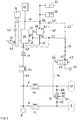
- Fig.1 shows a section of an electropneumatic brake system 1 a tractor-trailer combination with service brake and parking brake.
- the electropneumatic brake system 1 is preferably an electronically controlled brake system (EBS) with regard to the brake pressure.
- EBS electronically controlled brake system
- the brake system 1 is supplied in a known manner by one of a prime mover, in particular a self-igniting internal combustion engine driven compressor 2 with compressed air.
- a prime mover in particular a self-igniting internal combustion engine driven compressor 2 with compressed air.
- the compressor 2 via two compressed air supply lines 4, 6 with two compressed air supplies 8, 10 in connection, each of the compressed air supplies 8, 10 is associated with a service brake circuit of the service brake.
- an overflow valve 12, 14 is arranged in the compressed air supply lines 4, 6, each with a known purpose or function. It is so far Kreistrennung.
- service brake e.g. electric brake pedal module, brake control unit, pressure control modules, ABS pressure control valves, service brake cylinders are not shown here because they have no influence on the invention.
- the parking brake is here so compressed air supplied by the compressed air supplies 8, 10 of the service brake circuits.
- a separate supply of compressed air could also be present for the parking brake circuit.
- an overflow valve 24 and a check valve 26 are arranged for securing the circuit.
- the compressed air supply line 20 of the parking brake circuit is further connected to a supply terminal 28 of an electropneumatic brake control device 30, with which various functions in connection with the parking brake can be controlled, in particular known functions such as driving function, parking function, test function, bracing function and auxiliary brake function.
- the electropneumatic brake control device 30 can be designed as a structural unit and as such can be connected to an existing brake system, it can also be referred to as a parking brake module (Electronic Parking Brake Module, EPBM).
- EPBM Electrical Parking Brake Module
- a second output port 34 communicates with an electropneumatic trailer control valve or module 22 which controls the trailer brakes.
- the electropneumatic brake control device 30 includes an electromagnetic valve device 36 with solenoid valves such as intake valve, exhaust valve, bistable valve, etc., which is simply shown here as a box, by means of which, inter alia, a pneumatic control pressure for a pneumatic control input 40 of a relay valve 42 is produced at a connection 38, whose working output 44 is in communication with the first output port 32. Furthermore, the second one Output terminal 34 for the trailer control module 22 controllably connected to the valve means 36.
- solenoid valves such as intake valve, exhaust valve, bistable valve, etc.
- the electropneumatic brake control device 30 includes electronic control means 46 for controlling solenoid valves of the electropneumatic valve device 36, inter alia, dependent on parking brake signal input via a parking brake signal terminal 48 generated by a driver operable parking brake signal generator 50 such as a rocker switch or control lever. Furthermore, signals from integrated sensor devices such as pressure sensors are controlled in the electronic control device 46, which measure the actual pressures at the output terminals 32, 34 to realize a desired actual value in the control device 46, a brake pressure control, as for example in the context of Auxiliary braking is beneficial.
- the pneumatic part of the electropneumatic valve device 36 is supplied by the supply port 28 with the compressed air of the parking brake circuit.
- the control input 40 of the relay valve 42 is connected via a control air line 52 to the outlet 38 of the electropneumatic valve device 36 and a supply input 54 via a compressed air connection 56 to the supply port 28. It modulates on the basis of the supply pressure depending on the prevailing in the control air line 52 and controlled by the electropneumatic valve 36 control pressure a working pressure at its working output 44, which are then controlled via the first output port 32 in the spring brake cylinder 33.
- the first output port 32 is vented and vented to release.
- solenoid valves or electrically actuated components are preferably combined in the electromagnetic valve device 36, preferably no solenoid valves are present in the control air line 52.
- the brake system comprises a pneumatically controlled 2/2-way valve 58, with an inlet 60, which here preferably directly or directly via a first pressure connection 62 is connected to the control air line 52, connected to a pressure sink 68 outlet 64 and with a pneumatic control port 66 for a supply pressure of the service brake.
- the pressure sink is in the embodiment of Fig.1
- a vent 68 of the 2/2-way valve 58 is formed.
- the inlet 60 of the pneumatically controlled 2/2-way valve 58 may alternatively be connected or connectable to the working output 44 of the relay valve 42 and the first output port 32, optionally also by means of another valve device. Then, a corresponding terminal 53 'is provided. Alternatively, the first pressure connection 62 'could also be connected to the first output connection 32.
- the pneumatically controlled 2/2-way valve 58 has two positions, a passage or parking position, which is set at a supply pressure of the service brake at the control port 66 is less than a predetermined pressure limit and in which the inlet 60 is connected to the outlet 64, and a blocking or driving position, which is greater than a predetermined pressure limit at a supply pressure of the service brake and in which the inlet 60 is blocked from the outlet 64.
- the 2/2 directional control valve 58 is preferably a diaphragm valve which is controlled by the control pressure at its pneumatic control connection 66 and which is spring-loaded, for example, into its passage position. Then, when the supply pressure of the service brake drops below the pressure limit, the spring load of the valve member connected to the diaphragm for an automatic switching of the 2/2-way valve 58 in the passage or venting position.
- the 2/2-way valve 58 may be integrated into the electropneumatic brake control device 30, but here preferably represents a separate structural unit.
- the first pressure connection 62 branches off from the control air line 52 at a location between the outlet 38 of the valve device 36 and the control input 40 of the relay valve 42, so that here, for example, the control input 40 of the relay valve 42 without further interposition of solenoid valves directly or directly with the inlet 60th of the 2/2-way valve 58 is connected.
- the connection of the inlet 60 of the 2/2-way valve 58 to the control input 40 of the relay valve 42 may well be referred to as direct or direct.
- a selection device is provided here in the form of a shuttle valve 72 (Select High) for further control of the higher supply pressure from the supply pressures of the compressed air supplies 8, 10 to the pneumatic control port 66 of the 2/2-way valve 58.
- the pneumatic control connection 66 is connected via a second pressure connection 74 to an outlet 76 of the shuttle valve 72 whose first inlet 78 is connected to the first compressed air reservoir 8 of the first service brake circuit and the second inlet 80 to the second compressed air reservoir 10 of the second service brake circuit.
- the shuttle valve 72 then forms a logical "OR" member with respect to the supply pressures in the compressed air supplies 8, 10.
- the control pressure for the 2/2-way valve 58 is formed by the respective higher supply pressure of the service brake circuits.
- a throttle device 82, 84 is provided between the first compressed air reservoir 8 and the first inlet 78 of the shuttle valve and between the second compressed air reservoir 10 and the second inlet 80 of the shuttle valve in each case a throttle device 82, 84 is provided.
- the throttle cross-section is at least so small in both throttling devices 82, 84 that a volumetric flow which has unintentionally developed between the first inlet 78 and the second inlet 80 of the shuttle valve 72 is smaller than, for example, an undefined intermediate position of the valve member of the shuttle valve 72 minimal delivery volume flow, which the compressor 2 is able to deliver to the compressed air supplies 8, 10 with minimum delivery rate.
- the electrical components of the brake system 1 such as coils of the solenoid valves, sensor devices control device, etc. are powered by an electrical energy source such as a battery 86.
- the compressor 2 supplies at a conditional by actuation of the brake pedal of the service brake lowering of the reservoir pressure in the compressed air reservoirs 8, 10 of the two service brake circuits by Nachspecialized, so that the pressure limit is not exceeded under these circumstances.
- the pressure drop in the control air line 52 is also fed via the connection 38 into the valve device 36, which is designed to actuate a pressure signal representing a parked position at its connection 38 to the second output connection 34 for the trailer control valve 22 at such a pressure drop.
- This pressure signal may consist of a ventilation or venting of the second connection 34, depending on whether the brakes of the trailer are to be tensioned or released during parking.
- the pressure drop in the control air line 52 or at the connection 38 ensures, for example, at a pneumatic control input of a (likewise) pneumatically controlled bistable valve within the valve device 36 that the bistable valve controls the pressure signal representing the parking position to the second output connection 34 for the trailer control valve 22.
- the trailer brakes should be tightened when parking here. Since trailer control valves 22 are inverting with respect to the input pressure, in the case of the switching of the 2/2-way valve 58 into the passage or parking position and the resulting pressure drop due to the failure of the electric power supply 86 the control air line and thus at the terminal 38, the valve means 36 controlled so that the control pressure at the second output port 34 and also reduces the trailer control valve 22 and thereby the brake pressure for the brakes in the trailer is increased to Zuspanntik.
- the electrical power supply 86 preferably not only the spring-loaded brake cylinders of the towing vehicle but also the service brakes of the trailer are automatically tensioned.
- the control pressure for the 2/2-way valve 58 is formed by the respective higher reservoir pressure of the service brake circuits, so that nothing already a failure of a single service brake circuit, e.g. due to leakage leads to a reservoir pressure in this service brake circuit, which is below the pressure limit and then causes unnecessary switching of the 2/2-way valve 58 in the forward or parking position, as in such a leakage case is not necessarily a failure of the electrical power supply 86th must be present.
- Fig.2 shown another embodiment, identical or equivalent components are identified by the same reference numerals.
- the compressed air supply line 20 is secured for the parking brake circuit, for example via two check valves 16, 18, which are connected to the compressed air supply lines 4, 6 of the two service brake circuits.
- venting of the control air line 52 through the 2/2-way valve 58 does not take place via a vent 68 into the atmosphere, but by venting via a connected to the outlet 64 pressure line 88 to the outlet 76 of the shuttle valve 72 and from there either in the first compressed air supply 8 or in the second compressed air supply 10, depending on which compressed air supply 8 or 10, the larger reservoir pressure leads. Since the compressed air supplies 8, 10 of the service brake circuits due to the failure of the Power supply to be vented or are already, is between the control air line 52 and the respective compressed air supply 8, 10 the necessary pressure gradient available.
- a check valve 70 is arranged, through which a compressed air flow from the control air line 52 to the inlet 60 of the 2/2-way valve 58 and to the pressure sink 58 in the Passage position allows, but a compressed air flow from the inlet 60 and the pressure sink 58 is prevented in the control air line 52.
- the check valve 70 thus prevents pressurization of the control air line 52 and thus a release of the spring brake of the towing vehicle or the trailer brakes on the switched in passage position 2/2-way valve 58th
Landscapes
- Engineering & Computer Science (AREA)
- Transportation (AREA)
- Mechanical Engineering (AREA)
- Physics & Mathematics (AREA)
- Fluid Mechanics (AREA)
- Braking Systems And Boosters (AREA)
- Valves And Accessory Devices For Braking Systems (AREA)
Applications Claiming Priority (2)
| Application Number | Priority Date | Filing Date | Title |
|---|---|---|---|
| DE102014107278.2A DE102014107278A1 (de) | 2014-05-23 | 2014-05-23 | Elektropneumatische Bremssteuereinrichtung mit automatischer Entlüftung der Federspeicherbremse bei Stromausfall |
| PCT/EP2015/059023 WO2015176916A1 (de) | 2014-05-23 | 2015-04-27 | Elektropneumatische bremssteuereinrichtung mit automatischer entlüftung der federspeicherbremse bei stromausfall |
Publications (2)
| Publication Number | Publication Date |
|---|---|
| EP3145769A1 EP3145769A1 (de) | 2017-03-29 |
| EP3145769B1 true EP3145769B1 (de) | 2018-03-14 |
Family
ID=53016602
Family Applications (1)
| Application Number | Title | Priority Date | Filing Date |
|---|---|---|---|
| EP15719463.0A Active EP3145769B1 (de) | 2014-05-23 | 2015-04-27 | Elektropneumatische bremssteuereinrichtung mit automatischer entlüftung der federspeicherbremse bei stromausfall |
Country Status (7)
| Country | Link |
|---|---|
| US (1) | US9944266B2 (enExample) |
| EP (1) | EP3145769B1 (enExample) |
| KR (1) | KR20170010823A (enExample) |
| CN (1) | CN106458191B (enExample) |
| BR (1) | BR112016026810B1 (enExample) |
| DE (1) | DE102014107278A1 (enExample) |
| WO (1) | WO2015176916A1 (enExample) |
Cited By (7)
| Publication number | Priority date | Publication date | Assignee | Title |
|---|---|---|---|---|
| WO2021115827A1 (de) | 2019-12-10 | 2021-06-17 | Haldex Brake Products Aktiebolag | Bremsanlage eines nutzfahrzeugs |
| DE102023113581A1 (de) | 2023-05-24 | 2024-11-28 | Knorr-Bremse Systeme für Nutzfahrzeuge GmbH | Elektro-pneumatische Bremseinrichtung mit automatischer Entlüftung der Federspeicherbremse |
| DE102023136455A1 (de) * | 2023-12-22 | 2025-06-26 | Zf Cv Systems Global Gmbh | Elektropneumatische Feststellbremseinrichtung mit Feststellbremsredundanzeinheit |
| WO2025131582A1 (de) | 2023-12-22 | 2025-06-26 | Zf Cv Systems Global Gmbh | Elektropneumatische feststellbremseinrichtung mit notbremsfunktion |
| WO2025131583A1 (de) | 2023-12-22 | 2025-06-26 | Zf Cv Systems Global Gmbh | Elektropneumatische feststellbremseinrichtung mit parallelen entlüftungspfaden |
| DE102023136454A1 (de) * | 2023-12-22 | 2025-06-26 | Zf Cv Systems Global Gmbh | Elektronisch steuerbares pneumatisches Bremssystem mit einem Umkehrrelaisventil zum Be- und Entlüften eines Federspeicherbremszylinders eines Fahrzeugs |
| DE102023136451A1 (de) * | 2023-12-22 | 2025-06-26 | Zf Cv Systems Global Gmbh | Betriebsbremsentlüftungseinheit für eine betriebssichere Feststellbremsanordnung |
Families Citing this family (15)
| Publication number | Priority date | Publication date | Assignee | Title |
|---|---|---|---|---|
| DE102016205247A1 (de) * | 2016-03-30 | 2017-10-05 | Robert Bosch Gmbh | Bremssystem für ein Kraftfahrzeug, Verfahren zum Betreiben des Bremssystems |
| GB201611713D0 (en) * | 2016-07-05 | 2016-08-17 | Haldex Brake Prod Ab | Vehicle braking system |
| DE102017002716A1 (de) * | 2017-03-21 | 2018-09-27 | Wabco Gmbh | Elektronisch steuerbares Bremssystem sowie Verfahren zum Steuern des elektronisch steuerbaren Bremssystems |
| US10543826B2 (en) * | 2017-03-27 | 2020-01-28 | Bendix Commercial Vehicle Systems Llc | Valve system and method for controlling same |
| US10442418B2 (en) * | 2017-03-27 | 2019-10-15 | Bendix Commercial Vehicle Systems Llc | Valve system and method for controlling same |
| WO2019015762A1 (en) * | 2017-07-20 | 2019-01-24 | Volvo Lastvagnar Ab | USING A PARKING BRAKE SYSTEM TO IMPROVE DECELERATION OF A VEHICLE IN THE EVENT OF SERVICE BRAKE SYSTEM FAILURE |
| DE102017009307A1 (de) * | 2017-10-07 | 2019-04-11 | Wabco Gmbh | Parkbrems-Ventileinrichtung |
| KR102040827B1 (ko) * | 2018-03-20 | 2019-11-06 | 주식회사 만도 | 압력 제어 장치 및 압력 제어 방법 |
| DE102018117596A1 (de) | 2018-07-20 | 2020-01-23 | Wabco Gmbh | Elektropneumatisches Feststellbremsmodul mit direkt gesteuerten Ventilen und Anti-Compound-Anschluss |
| DE102019206501B4 (de) * | 2019-05-07 | 2021-10-21 | Volkswagen Aktiengesellschaft | Ausfallsichere Bremsvorrichtung für ein Kleinstfahrzeug |
| DE102020132875A1 (de) * | 2020-12-09 | 2022-06-09 | Zf Cv Systems Global Gmbh | Verfahren zum Noteinlegen einer Feststellbremse und elektropneumatisches Bremssystem |
| EP4043305B1 (en) | 2021-02-10 | 2023-10-11 | Volvo Truck Corporation | A pneumatic braking system for an axle of a vehicle |
| DE102021105755A1 (de) | 2021-03-10 | 2022-09-15 | Zf Cv Systems Global Gmbh | Verfahren zum Betreiben eines elektropneumatischen Feststellbremssystems und elektropneumatisches Feststellbremssystem |
| DE102021118895A1 (de) * | 2021-07-21 | 2023-01-26 | Zf Cv Systems Global Gmbh | Elektropneumatische Feststellbremseinheit mit Selbsthaltung im Fehlerfall |
| DE102023136452A1 (de) * | 2023-12-22 | 2025-06-26 | Zf Cv Systems Global Gmbh | Anordnung zur Druckluftversorgung eines pneumatischen Bremssystems und Verfahren zum Einlegen einer Feststellbremse durch Begrenzung der Fördermenge |
Family Cites Families (10)
| Publication number | Priority date | Publication date | Assignee | Title |
|---|---|---|---|---|
| DE10336611A1 (de) * | 2003-08-08 | 2005-03-03 | Wabco Gmbh & Co.Ohg | Druckmittelbetriebene Bremsanlage für ein Fahrzeug |
| DE102005058799A1 (de) * | 2005-12-09 | 2007-06-14 | Wabco Gmbh | Elektropneumatische Bremssteuerungseinrichtung |
| DE102005060225A1 (de) * | 2005-12-16 | 2007-06-21 | Wabco Gmbh | Elektropneumatische Bremssteuerungseinrichtung |
| DE102006041008A1 (de) * | 2006-08-31 | 2008-03-06 | Wabco Gmbh | Pneumatische Fahrzeugbremsanlage sowie Verfahren zum Steuern einer derartigen Bremsanlage |
| DE102006041012A1 (de) * | 2006-08-31 | 2008-03-06 | Wabco Gmbh | Ventileinheit, Bremssteuerungseinrichtung, Fahrzeugbremsanlage sowie Fahrzeug |
| DE102007047691A1 (de) * | 2007-10-05 | 2009-04-09 | Wabco Gmbh | Elektropneumatischer Feststellbremsmodulator zur Steuerung einer Feststellbremsfunktion von Bremsen eines Anhängefahrzeugs in einem Fahrzeugzug |
| DE102007047692A1 (de) * | 2007-10-05 | 2009-04-09 | Wabco Gmbh | Feststellbremsmodulator sowie Verwendung eines Bremsmodulators als Feststellbremsmodulator |
| DE102008009882A1 (de) * | 2008-02-19 | 2009-08-20 | Wabco Gmbh | Feststellbremse für ein Fahrzeug und Verfahren zum Betrieb der Feststellbremse |
| DE102008014547A1 (de) * | 2008-03-15 | 2009-09-17 | Wabco Gmbh | Bremsanlage für ein Fahrzeug |
| DE102008047632A1 (de) * | 2008-09-17 | 2010-03-25 | Knorr-Bremse Systeme für Nutzfahrzeuge GmbH | Feststellbremsanlage |
-
2014
- 2014-05-23 DE DE102014107278.2A patent/DE102014107278A1/de not_active Ceased
-
2015
- 2015-04-27 CN CN201580026842.7A patent/CN106458191B/zh active Active
- 2015-04-27 EP EP15719463.0A patent/EP3145769B1/de active Active
- 2015-04-27 BR BR112016026810-5A patent/BR112016026810B1/pt active IP Right Grant
- 2015-04-27 WO PCT/EP2015/059023 patent/WO2015176916A1/de not_active Ceased
- 2015-04-27 KR KR1020167035962A patent/KR20170010823A/ko not_active Abandoned
-
2016
- 2016-11-22 US US15/358,272 patent/US9944266B2/en active Active
Cited By (11)
| Publication number | Priority date | Publication date | Assignee | Title |
|---|---|---|---|---|
| WO2021115827A1 (de) | 2019-12-10 | 2021-06-17 | Haldex Brake Products Aktiebolag | Bremsanlage eines nutzfahrzeugs |
| DE102023113581A1 (de) | 2023-05-24 | 2024-11-28 | Knorr-Bremse Systeme für Nutzfahrzeuge GmbH | Elektro-pneumatische Bremseinrichtung mit automatischer Entlüftung der Federspeicherbremse |
| WO2024240469A1 (de) | 2023-05-24 | 2024-11-28 | Knorr-Bremse Systeme für Nutzfahrzeuge GmbH | Elektro-pneumatische bremseinrichtung mit automatischer entlüftung der federspeicherbremse |
| DE102023136455A1 (de) * | 2023-12-22 | 2025-06-26 | Zf Cv Systems Global Gmbh | Elektropneumatische Feststellbremseinrichtung mit Feststellbremsredundanzeinheit |
| WO2025131584A1 (de) | 2023-12-22 | 2025-06-26 | Zf Cv Systems Global Gmbh | Elektropneumatische feststellbremseinrichtung mit feststellbremsredundanzeinheit |
| WO2025131582A1 (de) | 2023-12-22 | 2025-06-26 | Zf Cv Systems Global Gmbh | Elektropneumatische feststellbremseinrichtung mit notbremsfunktion |
| WO2025131583A1 (de) | 2023-12-22 | 2025-06-26 | Zf Cv Systems Global Gmbh | Elektropneumatische feststellbremseinrichtung mit parallelen entlüftungspfaden |
| DE102023136454A1 (de) * | 2023-12-22 | 2025-06-26 | Zf Cv Systems Global Gmbh | Elektronisch steuerbares pneumatisches Bremssystem mit einem Umkehrrelaisventil zum Be- und Entlüften eines Federspeicherbremszylinders eines Fahrzeugs |
| DE102023136456A1 (de) * | 2023-12-22 | 2025-06-26 | Zf Cv Systems Global Gmbh | Elektropneumatische Feststellbremseinrichtung mit Notbremsfunktion |
| DE102023136451A1 (de) * | 2023-12-22 | 2025-06-26 | Zf Cv Systems Global Gmbh | Betriebsbremsentlüftungseinheit für eine betriebssichere Feststellbremsanordnung |
| DE102023136453A1 (de) * | 2023-12-22 | 2025-06-26 | Zf Cv Systems Global Gmbh | Elektropneumatische Feststellbremseinrichtung mit parallelen Entlüftungspfaden |
Also Published As
| Publication number | Publication date |
|---|---|
| US20170072930A1 (en) | 2017-03-16 |
| CN106458191B (zh) | 2019-02-15 |
| EP3145769A1 (de) | 2017-03-29 |
| BR112016026810B1 (pt) | 2022-09-27 |
| DE102014107278A1 (de) | 2015-11-26 |
| WO2015176916A1 (de) | 2015-11-26 |
| BR112016026810A2 (enExample) | 2017-08-15 |
| KR20170010823A (ko) | 2017-02-01 |
| CN106458191A (zh) | 2017-02-22 |
| US9944266B2 (en) | 2018-04-17 |
Similar Documents
| Publication | Publication Date | Title |
|---|---|---|
| EP3145769B1 (de) | Elektropneumatische bremssteuereinrichtung mit automatischer entlüftung der federspeicherbremse bei stromausfall | |
| EP3112230B1 (de) | Feststellbremsmodul, bremsanlage und fahrzeug damit sowie verfahren zum betreiben einer feststellbremseinrichtung mit einem solchen modul | |
| EP3668767B1 (de) | Elektropneumatisches feststellbremsmodul mit direkt gesteuerten ventilen | |
| EP1963151B1 (de) | Elektropneumatische bremssteuerungseinrichtung | |
| EP2055542B1 (de) | Druckmittelbetätigte Bremseinrichtung eines Zugfahrzeugs mit einem gegenläufige Drücke für Anhängerbremsen erzeugenden Festellbremsmodul | |
| EP2190706B1 (de) | Ventilanordnung zur steuerung einer bremsanlage eines anhängerfahrzeugs | |
| EP4396052B1 (de) | Betriebssichere parkbremsventileinheit mit einem bypassventil | |
| DE102017005979A1 (de) | Elektro-Pneumatische Handbremse (EPH) mit integrierten TCV (skandinavische Ansteuerung | |
| DE102005058799A1 (de) | Elektropneumatische Bremssteuerungseinrichtung | |
| EP1785325B2 (de) | Steuergerät für eine Druckluftbremsanlage eines Kraftfahrzeugs | |
| EP3129264A1 (de) | Elektropneumatische parkbremssteuereinrichtung | |
| EP3515771B1 (de) | Parkbremseinrichtung für ein nutzfahrzeug | |
| EP4466167B1 (de) | Betriebssichere feststellbremsventilanordnung mit einer wechselschaltung in reihe | |
| WO2017032617A1 (de) | Elektrische parkbremseinrichtung mit zusätzlicher energieversorgung | |
| DE102015106150A1 (de) | Parkbremseinrichtung für Kraftfahrzeuge | |
| EP3823868B1 (de) | Elektropneumatisches feststellbremsmodul mit direkt gesteuerten ventilen und anti-compound-anschluss | |
| EP3829946B1 (de) | Elektro-pneumatische handbremse (eph) mit teilweise entkoppelten tcv (europäische ansteuerung) | |
| EP3112231B1 (de) | Feststellbremsmodul, bremsanlage und fahrzeug damit sowie verfahren zum betreiben einer feststellbremseinrichtung mit einem solchen modul | |
| DE102017009954A1 (de) | Achsventilmodul und Relaisventilmodul einer Druckluftbremsanlage | |
| WO2008061798A2 (de) | Feststellbremsvorrichtung mit druckluftversorgungsleitungen für eine feststellbremse | |
| DE102023113581A1 (de) | Elektro-pneumatische Bremseinrichtung mit automatischer Entlüftung der Federspeicherbremse | |
| DE102023136454A1 (de) | Elektronisch steuerbares pneumatisches Bremssystem mit einem Umkehrrelaisventil zum Be- und Entlüften eines Federspeicherbremszylinders eines Fahrzeugs |
Legal Events
| Date | Code | Title | Description |
|---|---|---|---|
| PUAI | Public reference made under article 153(3) epc to a published international application that has entered the european phase |
Free format text: ORIGINAL CODE: 0009012 |
|
| 17P | Request for examination filed |
Effective date: 20161223 |
|
| AK | Designated contracting states |
Kind code of ref document: A1 Designated state(s): AL AT BE BG CH CY CZ DE DK EE ES FI FR GB GR HR HU IE IS IT LI LT LU LV MC MK MT NL NO PL PT RO RS SE SI SK SM TR |
|
| AX | Request for extension of the european patent |
Extension state: BA ME |
|
| DAV | Request for validation of the european patent (deleted) | ||
| DAX | Request for extension of the european patent (deleted) | ||
| GRAP | Despatch of communication of intention to grant a patent |
Free format text: ORIGINAL CODE: EPIDOSNIGR1 |
|
| INTG | Intention to grant announced |
Effective date: 20171016 |
|
| GRAS | Grant fee paid |
Free format text: ORIGINAL CODE: EPIDOSNIGR3 |
|
| GRAA | (expected) grant |
Free format text: ORIGINAL CODE: 0009210 |
|
| AK | Designated contracting states |
Kind code of ref document: B1 Designated state(s): AL AT BE BG CH CY CZ DE DK EE ES FI FR GB GR HR HU IE IS IT LI LT LU LV MC MK MT NL NO PL PT RO RS SE SI SK SM TR |
|
| REG | Reference to a national code |
Ref country code: GB Ref legal event code: FG4D Free format text: NOT ENGLISH |
|
| REG | Reference to a national code |
Ref country code: CH Ref legal event code: EP Ref country code: AT Ref legal event code: REF Ref document number: 978566 Country of ref document: AT Kind code of ref document: T Effective date: 20180315 |
|
| REG | Reference to a national code |
Ref country code: IE Ref legal event code: FG4D Free format text: LANGUAGE OF EP DOCUMENT: GERMAN |
|
| REG | Reference to a national code |
Ref country code: DE Ref legal event code: R096 Ref document number: 502015003438 Country of ref document: DE |
|
| REG | Reference to a national code |
Ref country code: FR Ref legal event code: PLFP Year of fee payment: 4 |
|
| REG | Reference to a national code |
Ref country code: NL Ref legal event code: FP |
|
| REG | Reference to a national code |
Ref country code: SE Ref legal event code: TRGR |
|
| REG | Reference to a national code |
Ref country code: LT Ref legal event code: MG4D |
|
| PG25 | Lapsed in a contracting state [announced via postgrant information from national office to epo] |
Ref country code: HR Free format text: LAPSE BECAUSE OF FAILURE TO SUBMIT A TRANSLATION OF THE DESCRIPTION OR TO PAY THE FEE WITHIN THE PRESCRIBED TIME-LIMIT Effective date: 20180314 Ref country code: LT Free format text: LAPSE BECAUSE OF FAILURE TO SUBMIT A TRANSLATION OF THE DESCRIPTION OR TO PAY THE FEE WITHIN THE PRESCRIBED TIME-LIMIT Effective date: 20180314 Ref country code: CY Free format text: LAPSE BECAUSE OF FAILURE TO SUBMIT A TRANSLATION OF THE DESCRIPTION OR TO PAY THE FEE WITHIN THE PRESCRIBED TIME-LIMIT Effective date: 20180314 Ref country code: NO Free format text: LAPSE BECAUSE OF FAILURE TO SUBMIT A TRANSLATION OF THE DESCRIPTION OR TO PAY THE FEE WITHIN THE PRESCRIBED TIME-LIMIT Effective date: 20180614 Ref country code: FI Free format text: LAPSE BECAUSE OF FAILURE TO SUBMIT A TRANSLATION OF THE DESCRIPTION OR TO PAY THE FEE WITHIN THE PRESCRIBED TIME-LIMIT Effective date: 20180314 |
|
| PG25 | Lapsed in a contracting state [announced via postgrant information from national office to epo] |
Ref country code: GR Free format text: LAPSE BECAUSE OF FAILURE TO SUBMIT A TRANSLATION OF THE DESCRIPTION OR TO PAY THE FEE WITHIN THE PRESCRIBED TIME-LIMIT Effective date: 20180615 Ref country code: LV Free format text: LAPSE BECAUSE OF FAILURE TO SUBMIT A TRANSLATION OF THE DESCRIPTION OR TO PAY THE FEE WITHIN THE PRESCRIBED TIME-LIMIT Effective date: 20180314 Ref country code: RS Free format text: LAPSE BECAUSE OF FAILURE TO SUBMIT A TRANSLATION OF THE DESCRIPTION OR TO PAY THE FEE WITHIN THE PRESCRIBED TIME-LIMIT Effective date: 20180314 Ref country code: BG Free format text: LAPSE BECAUSE OF FAILURE TO SUBMIT A TRANSLATION OF THE DESCRIPTION OR TO PAY THE FEE WITHIN THE PRESCRIBED TIME-LIMIT Effective date: 20180614 |
|
| PG25 | Lapsed in a contracting state [announced via postgrant information from national office to epo] |
Ref country code: MT Free format text: LAPSE BECAUSE OF FAILURE TO SUBMIT A TRANSLATION OF THE DESCRIPTION OR TO PAY THE FEE WITHIN THE PRESCRIBED TIME-LIMIT Effective date: 20180314 |
|
| PG25 | Lapsed in a contracting state [announced via postgrant information from national office to epo] |
Ref country code: RO Free format text: LAPSE BECAUSE OF FAILURE TO SUBMIT A TRANSLATION OF THE DESCRIPTION OR TO PAY THE FEE WITHIN THE PRESCRIBED TIME-LIMIT Effective date: 20180314 Ref country code: PL Free format text: LAPSE BECAUSE OF FAILURE TO SUBMIT A TRANSLATION OF THE DESCRIPTION OR TO PAY THE FEE WITHIN THE PRESCRIBED TIME-LIMIT Effective date: 20180314 Ref country code: AL Free format text: LAPSE BECAUSE OF FAILURE TO SUBMIT A TRANSLATION OF THE DESCRIPTION OR TO PAY THE FEE WITHIN THE PRESCRIBED TIME-LIMIT Effective date: 20180314 Ref country code: ES Free format text: LAPSE BECAUSE OF FAILURE TO SUBMIT A TRANSLATION OF THE DESCRIPTION OR TO PAY THE FEE WITHIN THE PRESCRIBED TIME-LIMIT Effective date: 20180314 Ref country code: EE Free format text: LAPSE BECAUSE OF FAILURE TO SUBMIT A TRANSLATION OF THE DESCRIPTION OR TO PAY THE FEE WITHIN THE PRESCRIBED TIME-LIMIT Effective date: 20180314 |
|
| PG25 | Lapsed in a contracting state [announced via postgrant information from national office to epo] |
Ref country code: SM Free format text: LAPSE BECAUSE OF FAILURE TO SUBMIT A TRANSLATION OF THE DESCRIPTION OR TO PAY THE FEE WITHIN THE PRESCRIBED TIME-LIMIT Effective date: 20180314 Ref country code: CZ Free format text: LAPSE BECAUSE OF FAILURE TO SUBMIT A TRANSLATION OF THE DESCRIPTION OR TO PAY THE FEE WITHIN THE PRESCRIBED TIME-LIMIT Effective date: 20180314 Ref country code: SK Free format text: LAPSE BECAUSE OF FAILURE TO SUBMIT A TRANSLATION OF THE DESCRIPTION OR TO PAY THE FEE WITHIN THE PRESCRIBED TIME-LIMIT Effective date: 20180314 |
|
| REG | Reference to a national code |
Ref country code: CH Ref legal event code: PL |
|
| REG | Reference to a national code |
Ref country code: DE Ref legal event code: R097 Ref document number: 502015003438 Country of ref document: DE |
|
| REG | Reference to a national code |
Ref country code: BE Ref legal event code: MM Effective date: 20180430 |
|
| PG25 | Lapsed in a contracting state [announced via postgrant information from national office to epo] |
Ref country code: PT Free format text: LAPSE BECAUSE OF FAILURE TO SUBMIT A TRANSLATION OF THE DESCRIPTION OR TO PAY THE FEE WITHIN THE PRESCRIBED TIME-LIMIT Effective date: 20180716 |
|
| PLBE | No opposition filed within time limit |
Free format text: ORIGINAL CODE: 0009261 |
|
| STAA | Information on the status of an ep patent application or granted ep patent |
Free format text: STATUS: NO OPPOSITION FILED WITHIN TIME LIMIT |
|
| REG | Reference to a national code |
Ref country code: IE Ref legal event code: MM4A |
|
| PG25 | Lapsed in a contracting state [announced via postgrant information from national office to epo] |
Ref country code: LU Free format text: LAPSE BECAUSE OF NON-PAYMENT OF DUE FEES Effective date: 20180427 Ref country code: DK Free format text: LAPSE BECAUSE OF FAILURE TO SUBMIT A TRANSLATION OF THE DESCRIPTION OR TO PAY THE FEE WITHIN THE PRESCRIBED TIME-LIMIT Effective date: 20180314 Ref country code: MC Free format text: LAPSE BECAUSE OF FAILURE TO SUBMIT A TRANSLATION OF THE DESCRIPTION OR TO PAY THE FEE WITHIN THE PRESCRIBED TIME-LIMIT Effective date: 20180314 |
|
| 26N | No opposition filed |
Effective date: 20181217 |
|
| PG25 | Lapsed in a contracting state [announced via postgrant information from national office to epo] |
Ref country code: LI Free format text: LAPSE BECAUSE OF NON-PAYMENT OF DUE FEES Effective date: 20180430 Ref country code: CH Free format text: LAPSE BECAUSE OF NON-PAYMENT OF DUE FEES Effective date: 20180430 Ref country code: BE Free format text: LAPSE BECAUSE OF NON-PAYMENT OF DUE FEES Effective date: 20180430 Ref country code: SI Free format text: LAPSE BECAUSE OF FAILURE TO SUBMIT A TRANSLATION OF THE DESCRIPTION OR TO PAY THE FEE WITHIN THE PRESCRIBED TIME-LIMIT Effective date: 20180314 |
|
| PG25 | Lapsed in a contracting state [announced via postgrant information from national office to epo] |
Ref country code: IE Free format text: LAPSE BECAUSE OF NON-PAYMENT OF DUE FEES Effective date: 20180427 |
|
| PGFP | Annual fee paid to national office [announced via postgrant information from national office to epo] |
Ref country code: NL Payment date: 20190418 Year of fee payment: 5 |
|
| PGFP | Annual fee paid to national office [announced via postgrant information from national office to epo] |
Ref country code: IT Payment date: 20190419 Year of fee payment: 5 |
|
| PG25 | Lapsed in a contracting state [announced via postgrant information from national office to epo] |
Ref country code: TR Free format text: LAPSE BECAUSE OF FAILURE TO SUBMIT A TRANSLATION OF THE DESCRIPTION OR TO PAY THE FEE WITHIN THE PRESCRIBED TIME-LIMIT Effective date: 20180314 |
|
| PG25 | Lapsed in a contracting state [announced via postgrant information from national office to epo] |
Ref country code: MK Free format text: LAPSE BECAUSE OF NON-PAYMENT OF DUE FEES Effective date: 20180314 Ref country code: HU Free format text: LAPSE BECAUSE OF FAILURE TO SUBMIT A TRANSLATION OF THE DESCRIPTION OR TO PAY THE FEE WITHIN THE PRESCRIBED TIME-LIMIT; INVALID AB INITIO Effective date: 20150427 |
|
| PG25 | Lapsed in a contracting state [announced via postgrant information from national office to epo] |
Ref country code: IS Free format text: LAPSE BECAUSE OF FAILURE TO SUBMIT A TRANSLATION OF THE DESCRIPTION OR TO PAY THE FEE WITHIN THE PRESCRIBED TIME-LIMIT Effective date: 20180714 |
|
| REG | Reference to a national code |
Ref country code: NL Ref legal event code: MM Effective date: 20200501 |
|
| PG25 | Lapsed in a contracting state [announced via postgrant information from national office to epo] |
Ref country code: NL Free format text: LAPSE BECAUSE OF NON-PAYMENT OF DUE FEES Effective date: 20200501 |
|
| REG | Reference to a national code |
Ref country code: AT Ref legal event code: MM01 Ref document number: 978566 Country of ref document: AT Kind code of ref document: T Effective date: 20200427 |
|
| PG25 | Lapsed in a contracting state [announced via postgrant information from national office to epo] |
Ref country code: AT Free format text: LAPSE BECAUSE OF NON-PAYMENT OF DUE FEES Effective date: 20200427 |
|
| PG25 | Lapsed in a contracting state [announced via postgrant information from national office to epo] |
Ref country code: IT Free format text: LAPSE BECAUSE OF NON-PAYMENT OF DUE FEES Effective date: 20200427 |
|
| P01 | Opt-out of the competence of the unified patent court (upc) registered |
Effective date: 20230607 |
|
| PGFP | Annual fee paid to national office [announced via postgrant information from national office to epo] |
Ref country code: DE Payment date: 20250428 Year of fee payment: 11 |
|
| PGFP | Annual fee paid to national office [announced via postgrant information from national office to epo] |
Ref country code: GB Payment date: 20250422 Year of fee payment: 11 |
|
| PGFP | Annual fee paid to national office [announced via postgrant information from national office to epo] |
Ref country code: FR Payment date: 20250424 Year of fee payment: 11 |
|
| PGFP | Annual fee paid to national office [announced via postgrant information from national office to epo] |
Ref country code: SE Payment date: 20250424 Year of fee payment: 11 |