EP3145689B1 - Bio-impression sans formation de couches par projection optique dynamique et ses utilisations - Google Patents
Bio-impression sans formation de couches par projection optique dynamique et ses utilisations Download PDFInfo
- Publication number
- EP3145689B1 EP3145689B1 EP15795499.1A EP15795499A EP3145689B1 EP 3145689 B1 EP3145689 B1 EP 3145689B1 EP 15795499 A EP15795499 A EP 15795499A EP 3145689 B1 EP3145689 B1 EP 3145689B1
- Authority
- EP
- European Patent Office
- Prior art keywords
- neural
- light
- cell
- wells
- stage
- Prior art date
- Legal status (The legal status is an assumption and is not a legal conclusion. Google has not performed a legal analysis and makes no representation as to the accuracy of the status listed.)
- Active
Links
- 230000003287 optical effect Effects 0.000 title claims description 44
- 238000000034 method Methods 0.000 claims description 63
- 239000000463 material Substances 0.000 claims description 56
- 239000000758 substrate Substances 0.000 claims description 41
- 229920001730 Moisture cure polyurethane Polymers 0.000 claims description 24
- 230000033001 locomotion Effects 0.000 claims description 15
- 239000012620 biological material Substances 0.000 claims description 14
- 229920001940 conductive polymer Polymers 0.000 claims description 10
- 238000007654 immersion Methods 0.000 claims description 7
- 230000000977 initiatory effect Effects 0.000 claims description 3
- 230000008093 supporting effect Effects 0.000 claims description 3
- 230000001537 neural effect Effects 0.000 description 73
- 210000004027 cell Anatomy 0.000 description 48
- 238000007639 printing Methods 0.000 description 42
- 210000002569 neuron Anatomy 0.000 description 38
- 239000000017 hydrogel Substances 0.000 description 29
- 239000000243 solution Substances 0.000 description 29
- 238000013528 artificial neural network Methods 0.000 description 28
- 238000004519 manufacturing process Methods 0.000 description 26
- 238000006116 polymerization reaction Methods 0.000 description 23
- 238000013459 approach Methods 0.000 description 22
- 230000000638 stimulation Effects 0.000 description 22
- 108091006146 Channels Proteins 0.000 description 21
- 230000000694 effects Effects 0.000 description 20
- 238000000059 patterning Methods 0.000 description 19
- 238000010146 3D printing Methods 0.000 description 17
- 238000013529 biological neural network Methods 0.000 description 15
- 238000000338 in vitro Methods 0.000 description 14
- 230000008569 process Effects 0.000 description 14
- 210000001519 tissue Anatomy 0.000 description 14
- 230000003592 biomimetic effect Effects 0.000 description 13
- 238000004113 cell culture Methods 0.000 description 12
- 238000012549 training Methods 0.000 description 12
- 108010010803 Gelatin Proteins 0.000 description 11
- 239000008273 gelatin Substances 0.000 description 11
- 229920000159 gelatin Polymers 0.000 description 11
- 235000019322 gelatine Nutrition 0.000 description 11
- 235000011852 gelatine desserts Nutrition 0.000 description 11
- 238000001000 micrograph Methods 0.000 description 11
- 239000000203 mixture Substances 0.000 description 11
- 230000004044 response Effects 0.000 description 11
- 239000000523 sample Substances 0.000 description 11
- 238000013461 design Methods 0.000 description 10
- 239000011521 glass Substances 0.000 description 10
- CERQOIWHTDAKMF-UHFFFAOYSA-M Methacrylate Chemical compound CC(=C)C([O-])=O CERQOIWHTDAKMF-UHFFFAOYSA-M 0.000 description 9
- 238000001727 in vivo Methods 0.000 description 9
- 229920000642 polymer Polymers 0.000 description 9
- 238000003491 array Methods 0.000 description 8
- 230000006399 behavior Effects 0.000 description 8
- 238000005516 engineering process Methods 0.000 description 8
- 230000006870 function Effects 0.000 description 8
- 210000004263 induced pluripotent stem cell Anatomy 0.000 description 8
- 230000003993 interaction Effects 0.000 description 8
- 230000035479 physiological effects, processes and functions Effects 0.000 description 8
- KIUKXJAPPMFGSW-DNGZLQJQSA-N (2S,3S,4S,5R,6R)-6-[(2S,3R,4R,5S,6R)-3-Acetamido-2-[(2S,3S,4R,5R,6R)-6-[(2R,3R,4R,5S,6R)-3-acetamido-2,5-dihydroxy-6-(hydroxymethyl)oxan-4-yl]oxy-2-carboxy-4,5-dihydroxyoxan-3-yl]oxy-5-hydroxy-6-(hydroxymethyl)oxan-4-yl]oxy-3,4,5-trihydroxyoxane-2-carboxylic acid Chemical compound CC(=O)N[C@H]1[C@H](O)O[C@H](CO)[C@@H](O)[C@@H]1O[C@H]1[C@H](O)[C@@H](O)[C@H](O[C@H]2[C@@H]([C@@H](O[C@H]3[C@@H]([C@@H](O)[C@H](O)[C@H](O3)C(O)=O)O)[C@H](O)[C@@H](CO)O2)NC(C)=O)[C@@H](C(O)=O)O1 KIUKXJAPPMFGSW-DNGZLQJQSA-N 0.000 description 7
- 238000003501 co-culture Methods 0.000 description 7
- 238000011960 computer-aided design Methods 0.000 description 7
- 238000005538 encapsulation Methods 0.000 description 7
- 230000014509 gene expression Effects 0.000 description 7
- 229920002674 hyaluronan Polymers 0.000 description 7
- 229960003160 hyaluronic acid Drugs 0.000 description 7
- 238000011160 research Methods 0.000 description 7
- 238000004422 calculation algorithm Methods 0.000 description 6
- 201000010099 disease Diseases 0.000 description 6
- 208000037265 diseases, disorders, signs and symptoms Diseases 0.000 description 6
- 238000011835 investigation Methods 0.000 description 6
- 108010037362 Extracellular Matrix Proteins Proteins 0.000 description 5
- 102000010834 Extracellular Matrix Proteins Human genes 0.000 description 5
- 102000001435 Synapsin Human genes 0.000 description 5
- 108050009621 Synapsin Proteins 0.000 description 5
- 108010046516 Wheat Germ Agglutinins Proteins 0.000 description 5
- 239000003814 drug Substances 0.000 description 5
- 210000002744 extracellular matrix Anatomy 0.000 description 5
- JUYQFRXNMVWASF-UHFFFAOYSA-M lithium;phenyl-(2,4,6-trimethylbenzoyl)phosphinate Chemical compound [Li+].CC1=CC(C)=CC(C)=C1C(=O)P([O-])(=O)C1=CC=CC=C1 JUYQFRXNMVWASF-UHFFFAOYSA-M 0.000 description 5
- 210000005155 neural progenitor cell Anatomy 0.000 description 5
- 229920001223 polyethylene glycol Polymers 0.000 description 5
- 108010043121 Green Fluorescent Proteins Proteins 0.000 description 4
- 102000004144 Green Fluorescent Proteins Human genes 0.000 description 4
- 108010050754 Halorhodopsins Proteins 0.000 description 4
- 230000000975 bioactive effect Effects 0.000 description 4
- 230000001413 cellular effect Effects 0.000 description 4
- 230000001419 dependent effect Effects 0.000 description 4
- 125000004386 diacrylate group Chemical group 0.000 description 4
- 238000002073 fluorescence micrograph Methods 0.000 description 4
- 230000003371 gabaergic effect Effects 0.000 description 4
- 230000000848 glutamatergic effect Effects 0.000 description 4
- 239000005090 green fluorescent protein Substances 0.000 description 4
- 238000003384 imaging method Methods 0.000 description 4
- 238000010348 incorporation Methods 0.000 description 4
- 230000007246 mechanism Effects 0.000 description 4
- 230000001404 mediated effect Effects 0.000 description 4
- 239000002953 phosphate buffered saline Substances 0.000 description 4
- 238000012216 screening Methods 0.000 description 4
- 230000000946 synaptic effect Effects 0.000 description 4
- 238000012360 testing method Methods 0.000 description 4
- 102000007469 Actins Human genes 0.000 description 3
- 108010085238 Actins Proteins 0.000 description 3
- 208000012902 Nervous system disease Diseases 0.000 description 3
- 239000002202 Polyethylene glycol Substances 0.000 description 3
- 230000004913 activation Effects 0.000 description 3
- QVGXLLKOCUKJST-UHFFFAOYSA-N atomic oxygen Chemical compound [O] QVGXLLKOCUKJST-UHFFFAOYSA-N 0.000 description 3
- 239000000560 biocompatible material Substances 0.000 description 3
- 210000004556 brain Anatomy 0.000 description 3
- 230000008614 cellular interaction Effects 0.000 description 3
- 230000036755 cellular response Effects 0.000 description 3
- 230000019771 cognition Effects 0.000 description 3
- 238000010586 diagram Methods 0.000 description 3
- 229940079593 drug Drugs 0.000 description 3
- 238000007877 drug screening Methods 0.000 description 3
- 230000005284 excitation Effects 0.000 description 3
- 238000012632 fluorescent imaging Methods 0.000 description 3
- 230000002102 hyperpolarization Effects 0.000 description 3
- 230000006872 improvement Effects 0.000 description 3
- 230000005764 inhibitory process Effects 0.000 description 3
- 230000010354 integration Effects 0.000 description 3
- 230000008611 intercellular interaction Effects 0.000 description 3
- 230000007774 longterm Effects 0.000 description 3
- 238000005259 measurement Methods 0.000 description 3
- 230000028161 membrane depolarization Effects 0.000 description 3
- 230000000877 morphologic effect Effects 0.000 description 3
- 210000003061 neural cell Anatomy 0.000 description 3
- 210000002241 neurite Anatomy 0.000 description 3
- 210000004498 neuroglial cell Anatomy 0.000 description 3
- 229910052760 oxygen Inorganic materials 0.000 description 3
- 239000001301 oxygen Substances 0.000 description 3
- 230000001575 pathological effect Effects 0.000 description 3
- 239000013612 plasmid Substances 0.000 description 3
- -1 poly(2-acrylamido-2-methylpropane sulfonic acid) Polymers 0.000 description 3
- 102000004169 proteins and genes Human genes 0.000 description 3
- 108090000623 proteins and genes Proteins 0.000 description 3
- 229910052594 sapphire Inorganic materials 0.000 description 3
- 239000010980 sapphire Substances 0.000 description 3
- 238000001878 scanning electron micrograph Methods 0.000 description 3
- 238000012421 spiking Methods 0.000 description 3
- 239000000126 substance Substances 0.000 description 3
- 230000000007 visual effect Effects 0.000 description 3
- XLYOFNOQVPJJNP-UHFFFAOYSA-N water Chemical compound O XLYOFNOQVPJJNP-UHFFFAOYSA-N 0.000 description 3
- 208000024827 Alzheimer disease Diseases 0.000 description 2
- 108010035848 Channelrhodopsins Proteins 0.000 description 2
- 208000025966 Neurological disease Diseases 0.000 description 2
- 102000010175 Opsin Human genes 0.000 description 2
- 108050001704 Opsin Proteins 0.000 description 2
- VYPSYNLAJGMNEJ-UHFFFAOYSA-N Silicium dioxide Chemical compound O=[Si]=O VYPSYNLAJGMNEJ-UHFFFAOYSA-N 0.000 description 2
- 238000002835 absorbance Methods 0.000 description 2
- 239000006096 absorbing agent Substances 0.000 description 2
- 230000008901 benefit Effects 0.000 description 2
- 238000013406 biomanufacturing process Methods 0.000 description 2
- 230000015572 biosynthetic process Effects 0.000 description 2
- 210000004413 cardiac myocyte Anatomy 0.000 description 2
- 230000021164 cell adhesion Effects 0.000 description 2
- 230000010261 cell growth Effects 0.000 description 2
- 239000003153 chemical reaction reagent Substances 0.000 description 2
- 230000004186 co-expression Effects 0.000 description 2
- 238000004132 cross linking Methods 0.000 description 2
- 238000011161 development Methods 0.000 description 2
- 230000018109 developmental process Effects 0.000 description 2
- VYFYYTLLBUKUHU-UHFFFAOYSA-N dopamine Chemical compound NCCC1=CC=C(O)C(O)=C1 VYFYYTLLBUKUHU-UHFFFAOYSA-N 0.000 description 2
- 229940000406 drug candidate Drugs 0.000 description 2
- 238000007876 drug discovery Methods 0.000 description 2
- 239000000975 dye Substances 0.000 description 2
- 230000007613 environmental effect Effects 0.000 description 2
- 238000011156 evaluation Methods 0.000 description 2
- 230000002964 excitative effect Effects 0.000 description 2
- 238000002474 experimental method Methods 0.000 description 2
- 210000002950 fibroblast Anatomy 0.000 description 2
- 238000000799 fluorescence microscopy Methods 0.000 description 2
- 230000002518 glial effect Effects 0.000 description 2
- 230000012010 growth Effects 0.000 description 2
- 238000013537 high throughput screening Methods 0.000 description 2
- 238000005286 illumination Methods 0.000 description 2
- 238000010874 in vitro model Methods 0.000 description 2
- 230000002401 inhibitory effect Effects 0.000 description 2
- 230000020796 long term synaptic depression Effects 0.000 description 2
- 230000027928 long-term synaptic potentiation Effects 0.000 description 2
- 210000003141 lower extremity Anatomy 0.000 description 2
- 230000005012 migration Effects 0.000 description 2
- 238000013508 migration Methods 0.000 description 2
- 230000003278 mimic effect Effects 0.000 description 2
- 238000012544 monitoring process Methods 0.000 description 2
- 239000002086 nanomaterial Substances 0.000 description 2
- 230000007514 neuronal growth Effects 0.000 description 2
- 238000000879 optical micrograph Methods 0.000 description 2
- 230000035755 proliferation Effects 0.000 description 2
- 210000001243 pseudopodia Anatomy 0.000 description 2
- 238000010526 radical polymerization reaction Methods 0.000 description 2
- 238000009877 rendering Methods 0.000 description 2
- 229920005989 resin Polymers 0.000 description 2
- 239000011347 resin Substances 0.000 description 2
- 238000001228 spectrum Methods 0.000 description 2
- 230000002269 spontaneous effect Effects 0.000 description 2
- 230000007480 spreading Effects 0.000 description 2
- 238000003892 spreading Methods 0.000 description 2
- 238000010186 staining Methods 0.000 description 2
- 210000000130 stem cell Anatomy 0.000 description 2
- 230000009897 systematic effect Effects 0.000 description 2
- 238000013334 tissue model Methods 0.000 description 2
- 238000013519 translation Methods 0.000 description 2
- 239000012780 transparent material Substances 0.000 description 2
- 230000002792 vascular Effects 0.000 description 2
- OZFAFGSSMRRTDW-UHFFFAOYSA-N (2,4-dichlorophenyl) benzenesulfonate Chemical compound ClC1=CC(Cl)=CC=C1OS(=O)(=O)C1=CC=CC=C1 OZFAFGSSMRRTDW-UHFFFAOYSA-N 0.000 description 1
- GJKGAPPUXSSCFI-UHFFFAOYSA-N 2-Hydroxy-4'-(2-hydroxyethoxy)-2-methylpropiophenone Chemical compound CC(C)(O)C(=O)C1=CC=C(OCCO)C=C1 GJKGAPPUXSSCFI-UHFFFAOYSA-N 0.000 description 1
- 238000012604 3D cell culture Methods 0.000 description 1
- 240000005020 Acaciella glauca Species 0.000 description 1
- 241001057184 Axion Species 0.000 description 1
- 206010048610 Cardiotoxicity Diseases 0.000 description 1
- 239000012591 Dulbecco’s Phosphate Buffered Saline Substances 0.000 description 1
- 108090000790 Enzymes Proteins 0.000 description 1
- 102000004190 Enzymes Human genes 0.000 description 1
- 102000016359 Fibronectins Human genes 0.000 description 1
- 108010067306 Fibronectins Proteins 0.000 description 1
- 238000001157 Fourier transform infrared spectrum Methods 0.000 description 1
- 102100039289 Glial fibrillary acidic protein Human genes 0.000 description 1
- 101710193519 Glial fibrillary acidic protein Proteins 0.000 description 1
- 229920002683 Glycosaminoglycan Polymers 0.000 description 1
- 101000979001 Homo sapiens Methionine aminopeptidase 2 Proteins 0.000 description 1
- 101000969087 Homo sapiens Microtubule-associated protein 2 Proteins 0.000 description 1
- 108090000862 Ion Channels Proteins 0.000 description 1
- 102000004310 Ion Channels Human genes 0.000 description 1
- 102100021118 Microtubule-associated protein 2 Human genes 0.000 description 1
- 206010029350 Neurotoxicity Diseases 0.000 description 1
- 229930040373 Paraformaldehyde Natural products 0.000 description 1
- 208000018737 Parkinson disease Diseases 0.000 description 1
- 101710189720 Porphobilinogen deaminase Proteins 0.000 description 1
- 102100034391 Porphobilinogen deaminase Human genes 0.000 description 1
- 101710170827 Porphobilinogen deaminase, chloroplastic Proteins 0.000 description 1
- 101710100896 Probable porphobilinogen deaminase Proteins 0.000 description 1
- 206010044221 Toxic encephalopathy Diseases 0.000 description 1
- 102000004243 Tubulin Human genes 0.000 description 1
- 108090000704 Tubulin Proteins 0.000 description 1
- 230000009471 action Effects 0.000 description 1
- 230000003213 activating effect Effects 0.000 description 1
- 230000003044 adaptive effect Effects 0.000 description 1
- 210000003484 anatomy Anatomy 0.000 description 1
- 238000010171 animal model Methods 0.000 description 1
- 230000002547 anomalous effect Effects 0.000 description 1
- 230000004888 barrier function Effects 0.000 description 1
- 238000010256 biochemical assay Methods 0.000 description 1
- 229920001222 biopolymer Polymers 0.000 description 1
- 231100000259 cardiotoxicity Toxicity 0.000 description 1
- 230000001364 causal effect Effects 0.000 description 1
- 230000024245 cell differentiation Effects 0.000 description 1
- 230000003915 cell function Effects 0.000 description 1
- 230000008619 cell matrix interaction Effects 0.000 description 1
- 230000009087 cell motility Effects 0.000 description 1
- 230000036978 cell physiology Effects 0.000 description 1
- 230000003833 cell viability Effects 0.000 description 1
- 230000033077 cellular process Effects 0.000 description 1
- 239000000919 ceramic Substances 0.000 description 1
- 230000008859 change Effects 0.000 description 1
- 238000006243 chemical reaction Methods 0.000 description 1
- 230000001149 cognitive effect Effects 0.000 description 1
- 239000003086 colorant Substances 0.000 description 1
- 238000004891 communication Methods 0.000 description 1
- 230000006854 communication Effects 0.000 description 1
- 230000000052 comparative effect Effects 0.000 description 1
- 230000009850 completed effect Effects 0.000 description 1
- 239000002131 composite material Substances 0.000 description 1
- 238000002591 computed tomography Methods 0.000 description 1
- 238000004883 computer application Methods 0.000 description 1
- 238000005094 computer simulation Methods 0.000 description 1
- 239000002322 conducting polymer Substances 0.000 description 1
- 238000010226 confocal imaging Methods 0.000 description 1
- 238000004624 confocal microscopy Methods 0.000 description 1
- 239000000470 constituent Substances 0.000 description 1
- 238000010276 construction Methods 0.000 description 1
- 238000010924 continuous production Methods 0.000 description 1
- 210000004748 cultured cell Anatomy 0.000 description 1
- 238000012258 culturing Methods 0.000 description 1
- 230000003013 cytotoxicity Effects 0.000 description 1
- 231100000135 cytotoxicity Toxicity 0.000 description 1
- 238000007418 data mining Methods 0.000 description 1
- 238000003745 diagnosis Methods 0.000 description 1
- 238000000502 dialysis Methods 0.000 description 1
- 230000004069 differentiation Effects 0.000 description 1
- 238000009792 diffusion process Methods 0.000 description 1
- 238000010790 dilution Methods 0.000 description 1
- 239000012895 dilution Substances 0.000 description 1
- LOKCTEFSRHRXRJ-UHFFFAOYSA-I dipotassium trisodium dihydrogen phosphate hydrogen phosphate dichloride Chemical compound P(=O)(O)(O)[O-].[K+].P(=O)(O)([O-])[O-].[Na+].[Na+].[Cl-].[K+].[Cl-].[Na+] LOKCTEFSRHRXRJ-UHFFFAOYSA-I 0.000 description 1
- 239000012153 distilled water Substances 0.000 description 1
- 229960003638 dopamine Drugs 0.000 description 1
- 238000001647 drug administration Methods 0.000 description 1
- 238000009509 drug development Methods 0.000 description 1
- 238000012912 drug discovery process Methods 0.000 description 1
- 238000003255 drug test Methods 0.000 description 1
- 230000008846 dynamic interplay Effects 0.000 description 1
- 230000002900 effect on cell Effects 0.000 description 1
- 210000000620 electrically active cell Anatomy 0.000 description 1
- 238000002001 electrophysiology Methods 0.000 description 1
- 230000007831 electrophysiology Effects 0.000 description 1
- 230000002708 enhancing effect Effects 0.000 description 1
- 230000001747 exhibiting effect Effects 0.000 description 1
- 238000001125 extrusion Methods 0.000 description 1
- 238000010304 firing Methods 0.000 description 1
- 230000004907 flux Effects 0.000 description 1
- 239000006260 foam Substances 0.000 description 1
- 230000005714 functional activity Effects 0.000 description 1
- 238000007306 functionalization reaction Methods 0.000 description 1
- 210000001222 gaba-ergic neuron Anatomy 0.000 description 1
- 238000012239 gene modification Methods 0.000 description 1
- 230000005017 genetic modification Effects 0.000 description 1
- 235000013617 genetically modified food Nutrition 0.000 description 1
- 210000005046 glial fibrillary acidic protein Anatomy 0.000 description 1
- 210000001362 glutamatergic neuron Anatomy 0.000 description 1
- 239000003102 growth factor Substances 0.000 description 1
- 239000001963 growth medium Substances 0.000 description 1
- 210000002064 heart cell Anatomy 0.000 description 1
- 230000002209 hydrophobic effect Effects 0.000 description 1
- 230000008676 import Effects 0.000 description 1
- 230000001976 improved effect Effects 0.000 description 1
- 238000000126 in silico method Methods 0.000 description 1
- 238000011065 in-situ storage Methods 0.000 description 1
- 238000007641 inkjet printing Methods 0.000 description 1
- 210000001153 interneuron Anatomy 0.000 description 1
- 230000003585 interneuronal effect Effects 0.000 description 1
- 238000002955 isolation Methods 0.000 description 1
- 239000007788 liquid Substances 0.000 description 1
- 231100000053 low toxicity Toxicity 0.000 description 1
- 238000002595 magnetic resonance imaging Methods 0.000 description 1
- 210000005171 mammalian brain Anatomy 0.000 description 1
- 238000007620 mathematical function Methods 0.000 description 1
- 238000002483 medication Methods 0.000 description 1
- 230000005499 meniscus Effects 0.000 description 1
- QSHDDOUJBYECFT-UHFFFAOYSA-N mercury Chemical compound [Hg] QSHDDOUJBYECFT-UHFFFAOYSA-N 0.000 description 1
- 229910052753 mercury Inorganic materials 0.000 description 1
- DCUFMVPCXCSVNP-UHFFFAOYSA-N methacrylic anhydride Chemical compound CC(=C)C(=O)OC(=O)C(C)=C DCUFMVPCXCSVNP-UHFFFAOYSA-N 0.000 description 1
- GDOPTJXRTPNYNR-UHFFFAOYSA-N methyl-cyclopentane Natural products CC1CCCC1 GDOPTJXRTPNYNR-UHFFFAOYSA-N 0.000 description 1
- 230000004048 modification Effects 0.000 description 1
- 238000012986 modification Methods 0.000 description 1
- 238000000465 moulding Methods 0.000 description 1
- 210000000653 nervous system Anatomy 0.000 description 1
- 230000000626 neurodegenerative effect Effects 0.000 description 1
- 238000002610 neuroimaging Methods 0.000 description 1
- 230000007171 neuropathology Effects 0.000 description 1
- 230000007135 neurotoxicity Effects 0.000 description 1
- 231100000228 neurotoxicity Toxicity 0.000 description 1
- 239000002858 neurotransmitter agent Substances 0.000 description 1
- 238000010899 nucleation Methods 0.000 description 1
- 235000015097 nutrients Nutrition 0.000 description 1
- 210000003463 organelle Anatomy 0.000 description 1
- 239000003960 organic solvent Substances 0.000 description 1
- 229920002866 paraformaldehyde Polymers 0.000 description 1
- 230000007310 pathophysiology Effects 0.000 description 1
- 230000002688 persistence Effects 0.000 description 1
- 229920003023 plastic Polymers 0.000 description 1
- 229920000671 polyethylene glycol diacrylate Polymers 0.000 description 1
- 239000011148 porous material Substances 0.000 description 1
- 230000001242 postsynaptic effect Effects 0.000 description 1
- 238000002360 preparation method Methods 0.000 description 1
- 238000012545 processing Methods 0.000 description 1
- 238000004393 prognosis Methods 0.000 description 1
- 230000002250 progressing effect Effects 0.000 description 1
- 230000002035 prolonged effect Effects 0.000 description 1
- 150000003254 radicals Chemical class 0.000 description 1
- 230000009467 reduction Effects 0.000 description 1
- 235000003499 redwood Nutrition 0.000 description 1
- 230000001172 regenerating effect Effects 0.000 description 1
- 230000002787 reinforcement Effects 0.000 description 1
- 230000010076 replication Effects 0.000 description 1
- 238000012827 research and development Methods 0.000 description 1
- 230000002441 reversible effect Effects 0.000 description 1
- 230000035945 sensitivity Effects 0.000 description 1
- 230000011664 signaling Effects 0.000 description 1
- 239000000377 silicon dioxide Substances 0.000 description 1
- 210000000329 smooth muscle myocyte Anatomy 0.000 description 1
- 238000002174 soft lithography Methods 0.000 description 1
- 241000894007 species Species 0.000 description 1
- 230000004936 stimulating effect Effects 0.000 description 1
- CXVGEDCSTKKODG-UHFFFAOYSA-N sulisobenzone Chemical compound C1=C(S(O)(=O)=O)C(OC)=CC(O)=C1C(=O)C1=CC=CC=C1 CXVGEDCSTKKODG-UHFFFAOYSA-N 0.000 description 1
- 238000004381 surface treatment Methods 0.000 description 1
- 230000002459 sustained effect Effects 0.000 description 1
- 210000000225 synapse Anatomy 0.000 description 1
- 230000003956 synaptic plasticity Effects 0.000 description 1
- 230000001360 synchronised effect Effects 0.000 description 1
- 238000003786 synthesis reaction Methods 0.000 description 1
- 230000002123 temporal effect Effects 0.000 description 1
- 238000009864 tensile test Methods 0.000 description 1
- 230000025934 tissue morphogenesis Effects 0.000 description 1
- 239000002407 tissue scaffold Substances 0.000 description 1
- 238000012876 topography Methods 0.000 description 1
- 238000001890 transfection Methods 0.000 description 1
- 238000012546 transfer Methods 0.000 description 1
- 230000001052 transient effect Effects 0.000 description 1
- 238000011282 treatment Methods 0.000 description 1
- 230000001960 triggered effect Effects 0.000 description 1
- 238000011144 upstream manufacturing Methods 0.000 description 1
- 238000001429 visible spectrum Methods 0.000 description 1
- 238000012800 visualization Methods 0.000 description 1
- 239000011800 void material Substances 0.000 description 1
Images


Classifications
-
- B—PERFORMING OPERATIONS; TRANSPORTING
- B33—ADDITIVE MANUFACTURING TECHNOLOGY
- B33Y—ADDITIVE MANUFACTURING, i.e. MANUFACTURING OF THREE-DIMENSIONAL [3-D] OBJECTS BY ADDITIVE DEPOSITION, ADDITIVE AGGLOMERATION OR ADDITIVE LAYERING, e.g. BY 3-D PRINTING, STEREOLITHOGRAPHY OR SELECTIVE LASER SINTERING
- B33Y80/00—Products made by additive manufacturing
-
- B—PERFORMING OPERATIONS; TRANSPORTING
- B29—WORKING OF PLASTICS; WORKING OF SUBSTANCES IN A PLASTIC STATE IN GENERAL
- B29C—SHAPING OR JOINING OF PLASTICS; SHAPING OF MATERIAL IN A PLASTIC STATE, NOT OTHERWISE PROVIDED FOR; AFTER-TREATMENT OF THE SHAPED PRODUCTS, e.g. REPAIRING
- B29C35/00—Heating, cooling or curing, e.g. crosslinking or vulcanising; Apparatus therefor
- B29C35/02—Heating or curing, e.g. crosslinking or vulcanizing during moulding, e.g. in a mould
- B29C35/08—Heating or curing, e.g. crosslinking or vulcanizing during moulding, e.g. in a mould by wave energy or particle radiation
- B29C35/0805—Heating or curing, e.g. crosslinking or vulcanizing during moulding, e.g. in a mould by wave energy or particle radiation using electromagnetic radiation
-
- B—PERFORMING OPERATIONS; TRANSPORTING
- B29—WORKING OF PLASTICS; WORKING OF SUBSTANCES IN A PLASTIC STATE IN GENERAL
- B29C—SHAPING OR JOINING OF PLASTICS; SHAPING OF MATERIAL IN A PLASTIC STATE, NOT OTHERWISE PROVIDED FOR; AFTER-TREATMENT OF THE SHAPED PRODUCTS, e.g. REPAIRING
- B29C35/00—Heating, cooling or curing, e.g. crosslinking or vulcanising; Apparatus therefor
- B29C35/02—Heating or curing, e.g. crosslinking or vulcanizing during moulding, e.g. in a mould
- B29C35/08—Heating or curing, e.g. crosslinking or vulcanizing during moulding, e.g. in a mould by wave energy or particle radiation
- B29C35/0888—Heating or curing, e.g. crosslinking or vulcanizing during moulding, e.g. in a mould by wave energy or particle radiation using transparant moulds
- B29C35/0894—Heating or curing, e.g. crosslinking or vulcanizing during moulding, e.g. in a mould by wave energy or particle radiation using transparant moulds provided with masks or diaphragms
-
- B—PERFORMING OPERATIONS; TRANSPORTING
- B29—WORKING OF PLASTICS; WORKING OF SUBSTANCES IN A PLASTIC STATE IN GENERAL
- B29C—SHAPING OR JOINING OF PLASTICS; SHAPING OF MATERIAL IN A PLASTIC STATE, NOT OTHERWISE PROVIDED FOR; AFTER-TREATMENT OF THE SHAPED PRODUCTS, e.g. REPAIRING
- B29C64/00—Additive manufacturing, i.e. manufacturing of three-dimensional [3D] objects by additive deposition, additive agglomeration or additive layering, e.g. by 3D printing, stereolithography or selective laser sintering
- B29C64/10—Processes of additive manufacturing
- B29C64/106—Processes of additive manufacturing using only liquids or viscous materials, e.g. depositing a continuous bead of viscous material
- B29C64/124—Processes of additive manufacturing using only liquids or viscous materials, e.g. depositing a continuous bead of viscous material using layers of liquid which are selectively solidified
- B29C64/129—Processes of additive manufacturing using only liquids or viscous materials, e.g. depositing a continuous bead of viscous material using layers of liquid which are selectively solidified characterised by the energy source therefor, e.g. by global irradiation combined with a mask
-
- B—PERFORMING OPERATIONS; TRANSPORTING
- B29—WORKING OF PLASTICS; WORKING OF SUBSTANCES IN A PLASTIC STATE IN GENERAL
- B29C—SHAPING OR JOINING OF PLASTICS; SHAPING OF MATERIAL IN A PLASTIC STATE, NOT OTHERWISE PROVIDED FOR; AFTER-TREATMENT OF THE SHAPED PRODUCTS, e.g. REPAIRING
- B29C64/00—Additive manufacturing, i.e. manufacturing of three-dimensional [3D] objects by additive deposition, additive agglomeration or additive layering, e.g. by 3D printing, stereolithography or selective laser sintering
- B29C64/20—Apparatus for additive manufacturing; Details thereof or accessories therefor
- B29C64/264—Arrangements for irradiation
- B29C64/277—Arrangements for irradiation using multiple radiation means, e.g. micromirrors or multiple light-emitting diodes [LED]
-
- B—PERFORMING OPERATIONS; TRANSPORTING
- B29—WORKING OF PLASTICS; WORKING OF SUBSTANCES IN A PLASTIC STATE IN GENERAL
- B29C—SHAPING OR JOINING OF PLASTICS; SHAPING OF MATERIAL IN A PLASTIC STATE, NOT OTHERWISE PROVIDED FOR; AFTER-TREATMENT OF THE SHAPED PRODUCTS, e.g. REPAIRING
- B29C64/00—Additive manufacturing, i.e. manufacturing of three-dimensional [3D] objects by additive deposition, additive agglomeration or additive layering, e.g. by 3D printing, stereolithography or selective laser sintering
- B29C64/30—Auxiliary operations or equipment
- B29C64/386—Data acquisition or data processing for additive manufacturing
-
- B—PERFORMING OPERATIONS; TRANSPORTING
- B29—WORKING OF PLASTICS; WORKING OF SUBSTANCES IN A PLASTIC STATE IN GENERAL
- B29C—SHAPING OR JOINING OF PLASTICS; SHAPING OF MATERIAL IN A PLASTIC STATE, NOT OTHERWISE PROVIDED FOR; AFTER-TREATMENT OF THE SHAPED PRODUCTS, e.g. REPAIRING
- B29C64/00—Additive manufacturing, i.e. manufacturing of three-dimensional [3D] objects by additive deposition, additive agglomeration or additive layering, e.g. by 3D printing, stereolithography or selective laser sintering
- B29C64/40—Structures for supporting 3D objects during manufacture and intended to be sacrificed after completion thereof
-
- B—PERFORMING OPERATIONS; TRANSPORTING
- B33—ADDITIVE MANUFACTURING TECHNOLOGY
- B33Y—ADDITIVE MANUFACTURING, i.e. MANUFACTURING OF THREE-DIMENSIONAL [3-D] OBJECTS BY ADDITIVE DEPOSITION, ADDITIVE AGGLOMERATION OR ADDITIVE LAYERING, e.g. BY 3-D PRINTING, STEREOLITHOGRAPHY OR SELECTIVE LASER SINTERING
- B33Y10/00—Processes of additive manufacturing
-
- B—PERFORMING OPERATIONS; TRANSPORTING
- B33—ADDITIVE MANUFACTURING TECHNOLOGY
- B33Y—ADDITIVE MANUFACTURING, i.e. MANUFACTURING OF THREE-DIMENSIONAL [3-D] OBJECTS BY ADDITIVE DEPOSITION, ADDITIVE AGGLOMERATION OR ADDITIVE LAYERING, e.g. BY 3-D PRINTING, STEREOLITHOGRAPHY OR SELECTIVE LASER SINTERING
- B33Y30/00—Apparatus for additive manufacturing; Details thereof or accessories therefor
-
- B—PERFORMING OPERATIONS; TRANSPORTING
- B33—ADDITIVE MANUFACTURING TECHNOLOGY
- B33Y—ADDITIVE MANUFACTURING, i.e. MANUFACTURING OF THREE-DIMENSIONAL [3-D] OBJECTS BY ADDITIVE DEPOSITION, ADDITIVE AGGLOMERATION OR ADDITIVE LAYERING, e.g. BY 3-D PRINTING, STEREOLITHOGRAPHY OR SELECTIVE LASER SINTERING
- B33Y50/00—Data acquisition or data processing for additive manufacturing
- B33Y50/02—Data acquisition or data processing for additive manufacturing for controlling or regulating additive manufacturing processes
-
- B—PERFORMING OPERATIONS; TRANSPORTING
- B33—ADDITIVE MANUFACTURING TECHNOLOGY
- B33Y—ADDITIVE MANUFACTURING, i.e. MANUFACTURING OF THREE-DIMENSIONAL [3-D] OBJECTS BY ADDITIVE DEPOSITION, ADDITIVE AGGLOMERATION OR ADDITIVE LAYERING, e.g. BY 3-D PRINTING, STEREOLITHOGRAPHY OR SELECTIVE LASER SINTERING
- B33Y70/00—Materials specially adapted for additive manufacturing
-
- G—PHYSICS
- G01—MEASURING; TESTING
- G01N—INVESTIGATING OR ANALYSING MATERIALS BY DETERMINING THEIR CHEMICAL OR PHYSICAL PROPERTIES
- G01N33/00—Investigating or analysing materials by specific methods not covered by groups G01N1/00 - G01N31/00
- G01N33/48—Biological material, e.g. blood, urine; Haemocytometers
- G01N33/50—Chemical analysis of biological material, e.g. blood, urine; Testing involving biospecific ligand binding methods; Immunological testing
- G01N33/5005—Chemical analysis of biological material, e.g. blood, urine; Testing involving biospecific ligand binding methods; Immunological testing involving human or animal cells
- G01N33/5008—Chemical analysis of biological material, e.g. blood, urine; Testing involving biospecific ligand binding methods; Immunological testing involving human or animal cells for testing or evaluating the effect of chemical or biological compounds, e.g. drugs, cosmetics
- G01N33/502—Chemical analysis of biological material, e.g. blood, urine; Testing involving biospecific ligand binding methods; Immunological testing involving human or animal cells for testing or evaluating the effect of chemical or biological compounds, e.g. drugs, cosmetics for testing non-proliferative effects
-
- G—PHYSICS
- G01—MEASURING; TESTING
- G01N—INVESTIGATING OR ANALYSING MATERIALS BY DETERMINING THEIR CHEMICAL OR PHYSICAL PROPERTIES
- G01N33/00—Investigating or analysing materials by specific methods not covered by groups G01N1/00 - G01N31/00
- G01N33/48—Biological material, e.g. blood, urine; Haemocytometers
- G01N33/50—Chemical analysis of biological material, e.g. blood, urine; Testing involving biospecific ligand binding methods; Immunological testing
- G01N33/5005—Chemical analysis of biological material, e.g. blood, urine; Testing involving biospecific ligand binding methods; Immunological testing involving human or animal cells
- G01N33/5008—Chemical analysis of biological material, e.g. blood, urine; Testing involving biospecific ligand binding methods; Immunological testing involving human or animal cells for testing or evaluating the effect of chemical or biological compounds, e.g. drugs, cosmetics
- G01N33/5044—Chemical analysis of biological material, e.g. blood, urine; Testing involving biospecific ligand binding methods; Immunological testing involving human or animal cells for testing or evaluating the effect of chemical or biological compounds, e.g. drugs, cosmetics involving specific cell types
- G01N33/5058—Neurological cells
-
- B—PERFORMING OPERATIONS; TRANSPORTING
- B29—WORKING OF PLASTICS; WORKING OF SUBSTANCES IN A PLASTIC STATE IN GENERAL
- B29C—SHAPING OR JOINING OF PLASTICS; SHAPING OF MATERIAL IN A PLASTIC STATE, NOT OTHERWISE PROVIDED FOR; AFTER-TREATMENT OF THE SHAPED PRODUCTS, e.g. REPAIRING
- B29C35/00—Heating, cooling or curing, e.g. crosslinking or vulcanising; Apparatus therefor
- B29C35/02—Heating or curing, e.g. crosslinking or vulcanizing during moulding, e.g. in a mould
- B29C35/08—Heating or curing, e.g. crosslinking or vulcanizing during moulding, e.g. in a mould by wave energy or particle radiation
- B29C35/0805—Heating or curing, e.g. crosslinking or vulcanizing during moulding, e.g. in a mould by wave energy or particle radiation using electromagnetic radiation
- B29C2035/0827—Heating or curing, e.g. crosslinking or vulcanizing during moulding, e.g. in a mould by wave energy or particle radiation using electromagnetic radiation using UV radiation
-
- B—PERFORMING OPERATIONS; TRANSPORTING
- B29—WORKING OF PLASTICS; WORKING OF SUBSTANCES IN A PLASTIC STATE IN GENERAL
- B29C—SHAPING OR JOINING OF PLASTICS; SHAPING OF MATERIAL IN A PLASTIC STATE, NOT OTHERWISE PROVIDED FOR; AFTER-TREATMENT OF THE SHAPED PRODUCTS, e.g. REPAIRING
- B29C35/00—Heating, cooling or curing, e.g. crosslinking or vulcanising; Apparatus therefor
- B29C35/02—Heating or curing, e.g. crosslinking or vulcanizing during moulding, e.g. in a mould
- B29C35/08—Heating or curing, e.g. crosslinking or vulcanizing during moulding, e.g. in a mould by wave energy or particle radiation
- B29C35/0805—Heating or curing, e.g. crosslinking or vulcanizing during moulding, e.g. in a mould by wave energy or particle radiation using electromagnetic radiation
- B29C2035/0838—Heating or curing, e.g. crosslinking or vulcanizing during moulding, e.g. in a mould by wave energy or particle radiation using electromagnetic radiation using laser
-
- B—PERFORMING OPERATIONS; TRANSPORTING
- B29—WORKING OF PLASTICS; WORKING OF SUBSTANCES IN A PLASTIC STATE IN GENERAL
- B29K—INDEXING SCHEME ASSOCIATED WITH SUBCLASSES B29B, B29C OR B29D, RELATING TO MOULDING MATERIALS OR TO MATERIALS FOR MOULDS, REINFORCEMENTS, FILLERS OR PREFORMED PARTS, e.g. INSERTS
- B29K2995/00—Properties of moulding materials, reinforcements, fillers, preformed parts or moulds
- B29K2995/0003—Properties of moulding materials, reinforcements, fillers, preformed parts or moulds having particular electrical or magnetic properties, e.g. piezoelectric
- B29K2995/0005—Conductive
-
- B—PERFORMING OPERATIONS; TRANSPORTING
- B29—WORKING OF PLASTICS; WORKING OF SUBSTANCES IN A PLASTIC STATE IN GENERAL
- B29K—INDEXING SCHEME ASSOCIATED WITH SUBCLASSES B29B, B29C OR B29D, RELATING TO MOULDING MATERIALS OR TO MATERIALS FOR MOULDS, REINFORCEMENTS, FILLERS OR PREFORMED PARTS, e.g. INSERTS
- B29K2995/00—Properties of moulding materials, reinforcements, fillers, preformed parts or moulds
- B29K2995/0037—Other properties
- B29K2995/0056—Biocompatible, e.g. biopolymers or bioelastomers
-
- B—PERFORMING OPERATIONS; TRANSPORTING
- B29—WORKING OF PLASTICS; WORKING OF SUBSTANCES IN A PLASTIC STATE IN GENERAL
- B29L—INDEXING SCHEME ASSOCIATED WITH SUBCLASS B29C, RELATING TO PARTICULAR ARTICLES
- B29L2031/00—Other particular articles
- B29L2031/752—Measuring equipment
-
- B—PERFORMING OPERATIONS; TRANSPORTING
- B29—WORKING OF PLASTICS; WORKING OF SUBSTANCES IN A PLASTIC STATE IN GENERAL
- B29L—INDEXING SCHEME ASSOCIATED WITH SUBCLASS B29C, RELATING TO PARTICULAR ARTICLES
- B29L2031/00—Other particular articles
- B29L2031/753—Medical equipment; Accessories therefor
- B29L2031/7532—Artificial members, protheses
Definitions
- the present invention relates to a system according to claim 1, and to a method for microfabrication of three-dimensional structures in photopolymers and fabricating biological scaffolds with smooth (layerless) contours, using said system.
- Laser micro-stereolithography (laser- ⁇ SL) techniques have grown to be popular for their abilities to create 3D scaffolds [Mapili et al., 2005; Gansel et al., 2009].
- scaffold fabrication using laser- ⁇ SL is usually slow due to point-by-point laser scanning.
- Many existing layer-by-layer stereolithographic methods do not feature a dynamically changing mask and simultaneous stage movement and therefore cause undesired layer artifacts that may alter cellular responses and not reflect the true native physiology.
- Carbon3D, Inc. Redwood City, CA
- One approach that has been commercialized by Carbon3D, Inc. (Redwood City, CA) for immersion printing of polymer nanostructures involves projecting an image through the transparent floor of a liquid resin reservoir while gradually lifting an immersed substrate away from the floor as the resin is cured on the bottom of the substrate.
- the oxygen permeable transparent floor of the bath allows for a "dead zone" of dissolved oxygen to inhibit polymerization at the floor of the bath.
- the techniques used in the Carbon3D system are described in numerous U.S. patents, issued and pending, to Joseph M. DeSimone, et al., including No. 8,263 129 .
- the reservoir and substrate of the Carbon3D system remain stationary, with only the immersed substrate moving within the z-axis to lift the printed object away from the floor as printing advances, which limits the varieties of shapes that can be created. Further, the technology's reliance on immersion limits the types and combinations of materials that may be used.
- 3D bioprinters capable of printing directly into multi-well plates are available from a number of companies, including the BioAssemblyBotTM bioprinter from Advanced Solutions, Inc. (Louisville, KY, US), the Regenova® bioprinter from Cyfuse Biomedical K.K. (Tokyo, JP), and the NovoGen MMXTM bioprinter from Invetech, Inc. (Melbourne, AU). These systems use a raster-scanning approach (i.e., "inkjet-like”) to fabricate the 3D constructs via extrusion of the biomaterial and, thus, suffer from inherent limitations in scalability, resolution, and material selection.
- a raster-scanning approach i.e., "inkjet-like
- Highly-specified 3D cell culture microenvironments can be utilized in a broad range of physiological contexts, including in vitro neuronal cultures.
- the goal of studying isolated neural cultures is to examine and probe a simple in vitro system that can represent physiologically relevant models.
- Isolated neural cultures are a cornerstone of neuroscience research, yet their utility in reflecting native physiology is limited due to their inherently indeterministic connectivity.
- the conditions used for these cultures vary drastically from the ones present in native tissue.
- the behavior of 2D cultures is not a good representation of the complex system that is the in vivo neural physiology.
- Recent work demonstrates that growing neurons in 3D scaffolds with incorporated glia provides drastic morphological and electrophysiological differences in comparison to neural networks grown in 2D cultures. This is attributed to the fact that 3D neural scaffolds better resemble the complex neural environment present in vivo.
- In vitro replication of neural circuitry may help elucidate essential parts of the neural milieu and facilitate testing of connectivity models that contribute to higher-level processes.
- iPSCs patient-specific induced pluripotent stem cells
- controlling the functional arrangement of neural populations may be critical to recreate normal versus pathological neural circuits.
- Conventional means for neuronal patterning are often restricted to a 2D context and use substrates that do not reflect native mechanochemical properties.
- methods to generate soft 3D scaffolds can be costly, time-consuming, or limited to simple geometric features. Given the limitations of current platforms, there is a need to establish a high-throughput means for deterministically controlling and systematically investigating the network dynamics of fundamental neural circuits in more physiologically representative, soft 3D environments.
- 3D constructs are essential to progress in the study of isolated neural networks and the development of physiologically relevant "brain-on- ⁇ -chip" systems. Recent advances in this area demonstrate the potential for sustaining neurons in 3D scaffolds for weeks while guiding neural growth in controlled geometric patterns.
- SOMAN ET AL. Digital microfabrication of user-defined 3D microstructures in cell-laden hydrogels
- BIOTECHNOL BIOENG vol. 110, no. 11, 3 June 2013, pages 3038-3047, XP055238110 discloses a system for 3d microfabrication of a structure in cell-laden hydrogels.
- a method and system are provided for rapid generation of polymeric scaffolds with highly specified 3D geometries.
- the biofabrication method is referred to herein as "Layerless 3D Printing via Dynamic Optical Projection", or "L3PDOP”.
- the L3PDOP 3D printing system and method can receive an input comprising a 3D computer-generated model and from that model generate the structure in a variety of photopolymerizable materials with high resolution.
- the 3D printing system uses a dynamically controlled DMD (digital micromirror device) to reflect a high resolution pattern of UV light onto a photopolymerizable substrate.
- DMD digital micromirror device
- Integration with custom computer software allows for the simultaneous and continuous control of the projected image and the linear stage that controls the position of the substrate in relation to the focal plane of projected light. Due to the continuous movement of the stage, the fabricated 3D structures have smooth (i.e., layerless) contours in the Z (vertical) direction.
- the composition of the pre-polymer solution for example, by inclusion of naturally-derived and/or synthetic biomaterials, bioactive molecules, heterogeneous cell populations, 3D structures that mimic native tissue environments can be created within seconds.
- rapid control of the micromirror array provides for micron and sub-micron level changes in local material properties (such as porosity and material stiffness) via spatiotemporal patterning of transient UV exposure throughout the polymer.
- a system and method for 3D microfabrication are provided by projecting light capable of initiating photopolymerization toward a spatial light modulator that modulates light responsive to digital masks corresponding to layers of the structure.
- Projection optics focus the modulated light onto an optical plane within a photopolymerizable material supported on a stage.
- a computer controller causes the spatial light modulator to project a sequence of images corresponding to the digital masks while coordinating movement of the stage to move a position of the optical plane within the photopolymerizable material to sequentially project each image of the sequence to generate the structure by progressively photopolymerizing the photopolymerizable material.
- the method and system provide a novel stereolithographic approach via dynamic continuous control of a micromirror array (DMD) along with a linear stage.
- DMD micromirror array
- the device allows for an improvement over the state of the art due to its speed, scalability, and layerless Z resolution.
- the fabricated structures do not exhibit the planar artifacts produced using traditional layer-by-layer fabrication approaches that involve discrete movement of the linear stage to a new height position.
- the L3PDOP 3D printing platform provides for rapid and scalable fabrication of highly-specified biomimetic structures. This approach provides capability in terms of speed and scalability that cannot be well-achieved using existing technologies that employ raster-based printing approaches or soft lithography techniques.
- this platform provides a method for generating models with specificity not only in terms of cell type but also whole tissue morphology.
- the flexibility of the platform allows for the modular addition and subsequent decoupling of various components of a complex 3D construct, providing a means to determine the individual contributions of material type, co-culture populations, spatial cell arrangements, and biomimetic geometries.
- Modes of operation for the apparatus include 3D microscale bioprinting of biological substrates via dynamic stereolithography, and optogenetic control of neurons with high spatiotemporal resolution, along with accompanying integrated capabilities for simultaneous electrophysiology and fluorescence imaging.
- Stereolithographic 3D bioprinting allows for photopolymerization of multiple biocompatible materials (e.g., PEGDA, MeHA, GelMA) and facilitates cell encapsulation within these structures. Additionally, these materials - along with their incorporated cell types - can be used heterogeneously in the same scaffold to provide 3D patterned co-culture substrates, thus facilitating the study of interactions among multiple cell phenotypes, e.g., neuronal/glial interactions.
- biocompatible materials e.g., PEGDA, MeHA, GelMA
- a pre-polymer solution containing free-radical absorbers to inhibit light-activated free-radical polymerization/cross-linking is used to limit the curing depth.
- a surface treatment may be applied to the window, which may be composed of sapphire or glass (or any other sufficiently rigid optically-transparent material), to prevent polymerization/adhesion of the structure onto the immersed window. This is in contrast to the Carbon3D approach, with printing using the platform occurring directly onto the floor of the bath as opposed to on an immersed probe. This allows the rapid printing of 3D structures within each well of a multi-well plate as the plate is translated within X-Y axes to move from well to well. By not relying on a single large bath immersion, each well can contain a different polymer composition and may ultimately hold a different 3D structure.
- the method and device are operable for recording network activity across multiple domains.
- multi-electrode arrays (MEAs) - on which the 3D neuron network structures (or any electrically active cell type) are printed - allow orthogonal recording of electrical activity concurrent with optogenetic stimulation; and 2) fluorescent imaging of voltage-sensitive dyes and proteins, which provides enhanced single-cell resolution of network activity, can be simultaneously performed by employing the same or similar light source utilized for bioprinting.
- a brain-on-a-chip is generated by integrating 3D heterogeneous neural cultures, optogenetics-enabled high-resolution stimulation, and parallel electrical and image-based recording of neural activity.
- the fabrication methods utilized in this platform offer control over both the topographical complexity and the cellular and material composition of the neural environment, thereby allowing for the potential for systematically-controlled increases in complexity.
- a system for 3D microfabrication of a structure includes a light source configured for projecting light within an optical path, the light source emitting light at a wavelength configured for initiating photopolymerization; a spatial light modulator disposed within the optical path and configured for modulating light from the light source responsive to a set of digital masks corresponding to layers of the structure; projection optics configured to focus the modulated light to an optical plane; a stage configured to support a substrate in contact with a photopolymerizable material within the optical plane, wherein the stage is configured for movement along at least one axis; and a computer processor operable for: controlling the spatial light modulator to project a sequence of images corresponding to the set of digital masks; and coordinating movement of the stage to move a position of the optical plane within the photopolymerizable material to sequentially project each image of the sequence to generate the structure by progressively photopolymerizing the photopolymerizable material along the at least one axis.
- the spatial light modulator may be a digital micromirror device.
- the photopolymerizable material may be a pre-polymer solution contained within a container, and the system further comprises a transparent window configured for contact with the pre-polymer solution, where an interface between the window and the pre-polymer solution is substantially coincident with the optical plane.
- the window is sealed to an end of a tube for immersion in the pre-polymer solution and the stage is moved away from the optical plane so that successive layers are polymerized on top of previously polymerized layers.
- the window may be treated to inhibit adhesion of the photopolymerizable material and may be formed from a material selected from the group consisting of silica, sapphire, polydimethysiloxane (PDMS), transparent ceramic, and transparent plastic.
- the container comprises a well within a multi-well plate.
- the multi-well plate comprises a plurality of containers, where at least of portion of the containers contain different pre-polymer solutions.
- the substrate comprises an electrode or a multi-electrode array.
- the electrode or multi-electrode array is contained within a well within a multi-well plate, which itself may comprise a plurality of containers, where at least of portion of the containers contain different types and numbers and spatial configurations of electrodes.
- the photopolymerizable material may be a conductive polymer and at least a portion of the sequence of images corresponds to interconnecting structures aligned with one or more electrodes.
- the photopolymerizable material may be a photo-crosslinkable hydrogel selected from the group consisting of gelatin methacrylate [GelMA], methacrylated hyaluronic acid [MeHA] and polyethylene glycol diacrylate [PEGDA].
- GelMA gelatin methacrylate
- MeHA methacrylated hyaluronic acid
- PEGDA polyethylene glycol diacrylate
- the system may include at least one second light source disposed within the optical path, the at least one second light source emitting light at one or more wavelengths configured to stimulate at least one photo-active biological material.
- the system may also include an image acquisition device disposed within the optical path.
- At least a portion of the digital masks may be configured to cause the spatial light modulator to generate subpatterns within selected layers of the structure.
- a method for 3D microfabrication of a structure includes controlling a spatial light modulator to project a sequence of patterns of light from at least one light source having an optical path and emitting at a wavelength configured to initiate photopolymerization onto a photopolymerizable substrate, wherein the substrate is mounted on a stage configured for movement along at least one axis, and wherein the sequence of patterns corresponds to layers of the structure; and simultaneously and continuously controlling the sequence of patterns and the stage movement to generate the structure by progressively photopolymerizing the photopolymerizable substrate along the at least one axis.
- the sequence of patterns is preferably generated by a set of digital masks communicated from a computer controller to the spatial light modulator.
- the photopolymerizable substrate comprises a pre-polymer solution contained within a container, and the method further comprises positioning a transparent window in contact with the pre-polymer solution to define the polymerization plane.
- the stage is moved toward the photopolymerization plane so that successive layers of the structure are projected through previously polymerized layers.
- the window is sealed to an end of a tube for immersion in the pre-polymer solution and the stage is moved away from the polymerization plane so that successive layers are polymerized on top of previously polymerized layers.
- the different stage movement directions may be combined, with some structures built from a combination of top-down and bottom-up stage movements.
- the container is a well within a multi-well plate that includes a plurality of containers, wherein at least of portion of the plurality of containers contain different pre-polymer solutions.
- the substrate may be an electrode or a multi-electrode array.
- the photopolymerizable substrate may be a conductive polymer and at least a portion of the sequence of patterns corresponds to interconnecting structures aligned with one or more electrodes.
- the photopolymerizable substrate may be a photo-crosslinkable hydrogel selected from the group consisting of gelatin methacrylate [GelMA], methacrylated hyaluronic acid [MeHA] and polyethylene glycol diacrylate [PEGDA].
- GelMA gelatin methacrylate
- MeHA methacrylated hyaluronic acid
- PEGDA polyethylene glycol diacrylate
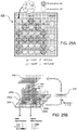
- FIG. 1A The basic elements of a L3PDOP 3D printing platform 100 according to an exemplary embodiment of the invention are illustrated in FIG. 1A : a UV light source 10, a computer controller/processor 12, which performs sliced image-flow generation, i.e., "virtual masks" 11, and system synchronization, a digital micromirror device (DMD) chip 13 for optical pattern generation, a projection optics assembly 14, and an multi-axis stage 15 for sample position control.
- the DMD chip 13 formed from approximately one million micro-mirrors, modulates the UV light and projects an optical pattern generated via computer 12 based on a custom-designed computer-aided design (CAD) model onto the photopolymer solution.
- CAD computer-aided design
- the optical pattern is projected through optical lenses 14 and onto the photosensitive biomaterial 16 to fabricate a 3D scaffold.
- Complex 3D structures are fabricated through a continuous, layer-by-layer polymerization process that is synchronically controlled using a motorized multi-axis stage 15.
- An appropriate UV light source 10 for use in the L3PDOP system can be selected from different sources including a laser (CW or pulsed), mercury bulb (arc lamp), and an LED source, which may include an array of LEDs emitting at one wavelength or across a range of UV wavelengths.
- a pulse mode-locked femtosecond laser may be used.
- the light source 10 may include controllable parameters, responsive to the computer controller/processor 12, including intensity, iris, aperture, exposure time, shutter, and wavelength. Selection of appropriate operating parameter will depend on the materials used and the desired characteristics of the scaffold and will be within the level of skill in the art.
- a galvanometer optical scanner or a polygon scanning mirror may be used as an alternative to the DMD chip. Both of these technologies, which are commercially available, are known in their application to high speed scanning confocal microscopy. Selection of an appropriate scanning mechanism for use in conjunction with the system and method will be within the level of skill in the art.
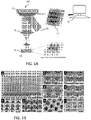
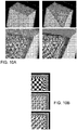
- FIG. 1B is a series of scanning electron microscope (SEM) images of PEG microwells with complex geometries including: (b) stepwise, (c) spiral, (d) embryo-like, and (e) flower-like.
- FIG 1B(a) is a combination of arrays of the structures shown in (b)-(e).
- FIG. 1B images (f)-(i) are the inverse of the microwells of (b)-(e), demonstrating the versatility of the L3PDOP printing method.
- the masks 11 are similar in form to a set of "PowerPoint-like" slides, and can be dynamically altered as per the CAD model to design and fabricate a wide variety of 3D features.
- a significant advantage of the system is that it does not require the use of organic solvents that may otherwise compromise the biocompatibility of the scaffold material.
- the 3D printing technology is ideal for high-throughput fabrication and is easily scalable, a necessary requirement for generating high-volume screening platforms.
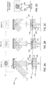
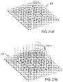
- FIGs. 2A-2C illustrate an exemplary process sequence for fabricating a 3D scaffold using the L3PDOP printing system 100 and method.
- the basic elements of the system 100 are a UV light source 110, a computer controller/processor (not shown), which performs sliced image-flow generation, i.e., "virtual masks" 111, a digital micromirror device (DMD) chip 113 for optical pattern generation, a projection optics assembly 114, and an multi-axis stage 115 for sample position control.
- Cells in a macromer solution 124 are placed in a chamber 126 covered by a transparent coverslip 128.
- the coverslip 128 is methacrylated glass.
- Polymerization of the 3D scaffold 130a begins at the coverslip surface 128, where the reflected UV image corresponding to Mask 1.0 from the DMD array 113 is focused at imaging/polymerization plane 120 in step 1 shown in FIG. 2A .
- Mask 1.0 represents the basic shape of a base portion 130a, which can be varied gradually in dimension, e.g., with multiple masks, up to Mask 1.0. n , being projected on the DMD, as the structure builds to generate sloped or curved edges.
- the projection mask on the DMD 113 shifts to Mask 2.0 - 2.0 .n as the servo-controlled platform 115 translates up to move the fabricated base portion 130a past the polymerization plane 120 (step (2) shown in FIG. 2B ) and to bring the next portion of the chamber 126 and macromer solution 124 into the polymerization plan 120 to form the second part of the scaffold 130b.
- the dimensions of the mask may be varied to create curved and slopes edges in the sample shape(s).
- the top of the scaffold 130c is reached in step (3) as determined by Mask 3.0 - 3.0. n ( FIG. 2c ).
- FIG. 2D diagrammatically illustrates a top view (upper) and side view (lower) of the exemplary 3D scaffold resulting from the steps shown in FIGs. 2A-2C .
- one or more one image acquisition devices may be included within the optical path to allow incident light or the projected image to be transformed through the projection optics assembly to allow a focal plane of the image to be coincident with the focal plane of said image acquisition device.
- the image acquisition device may be used to capture the incident light, the projected image, or a pattern of light emitted, reflected, transmitted, or otherwise transformed by said substrate.
- Appropriate image acquisition devices include CMOS cameras, CCD cameras or microscopes, e.g., fluorescent microscopes.
- a prototype of the L3PDOP micro-stereolithography (“ ⁇ SL”) system was constructed to fabricate 3D scaffolds such as a tube, conduit, log-pile, and vascular-like structure.
- the system has been used to create structures from various biopolymers including polyethylene glycol diacrylate (PEGDA, functionalized with fibronectin for cell adhesion), methacrylated hyaluronic acid (MeHA), and gelatin methacrylate (GelMA) for the 3D scaffolds.
- PEGDA polyethylene glycol diacrylate
- MeHA methacrylated hyaluronic acid
- GalMA gelatin methacrylate
- Encapsulated cells demonstrate good cell viability across all geometries both on the scaffold surface and internal to the structures. Cells respond to geometric cues individually as well as collectively throughout the larger-scale patterns.
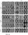
- FIG. 3 provides micrographs of examples of cellular response to complex 3D geometric cues, demonstrating dynamic interaction with the scaffolds to remodel the position and shape of the structures.
- Upper panel (a) shows GelMA (gelatin methacrylate) scaffolds with encapsulated NIH/3T3 cells at 12 hrs post-fabrication.
- Second panel (b) reveals deformation of the structures as observed four days post-encapsulation.
- Panel (c) is a 3D reconstruction of confocal fluorescence micrographs indicating height-dependent deformation of the scaffold as mediated by cell-cell interactions across two flower structures (third image of panel (b). Cells were stained for F-actin (red) and nuclei (blue).
- Panel (d) individual Z sections of the same flower structures as shown in panel (c) demonstrate height-dependent deformation when progressing up from the floor to the top of the structures. All scale bars are 100 ⁇ m.
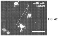
- FIGs. 4A-4C provide micrographs of cells that remain encapsulated within the GelMA scaffolds, exhibiting 3D cell spreading while maintaining active cell-material interactions. Confocal fluorescence micrographs reconstructed in 3D ( FIG. 4A ) and viewed at various Z planes ( FIG. 4B ) throughout the scaffold reveal NIH/3T3 fibroblasts on the scaffold surface displaying morphology different from cells internal to the structures.
- FIG. 4B cells that remain embedded within the GelMA scaffold at 4 days post-encapsulation exhibit extension of pseudopodia preferentially towards the surface of the encapsulating structure. Cells were stained for F-actin (red) and nuclei (blue).
- FIG. 4A-4C provide micrographs of cells that remain encapsulated within the GelMA scaffolds, exhibiting 3D cell spreading while maintaining active cell-material interactions. Confocal fluorescence micrographs reconstructed in 3D ( FIG. 4A ) and viewed at various Z planes ( FIG. 4B ) throughout the scaffold reveal
- 10T1/2 cells encapsulated within GelMA scaffolds express a smooth muscle cell phenotype, as shown via staining for ⁇ -SM actin (green), and maintain cell-material interactions at 8 days post-encapsulation as indicated by 3D projections of pseudopodia. All scale bars are 50 ⁇ m.
- FIG. 5 is a set of fluorescence micrographs (A-D) showing examples of various 3D scaffolds constructed from hyaluronic acid using the 3D printing platform.
- FIG. 6A is a scanning electron micrograph of a log-pile scaffold and
- FIG. 6B is an optical micrograph of a vascular microstructure made of GelMA using the L3PDOP printing platform.
- the CAD model for generating masks for L3PDOP printing of the 3D scaffold generally consists of a series of slices of digital images.
- the images may also be derived from MRI or CT scans.
- the control computer and appropriate software With the control computer and appropriate software, the images are automatically and continuously loaded one-by-one into the DMD chip and then projected into the photo-polymerizable materials to form 3D structures through a digital, continuous polymerization process.
- the flexibility of the platform allows for the modular addition and subsequent decoupling of various components of a complex 3D construct, providing a means to determine the individual contributions of material type, co-culture populations, spatial cell arrangements, and biomimetic geometries.
- the instrumentation for the system may be controlled via software built in Visual C++ or Go (golang.org) or similar object-oriented programming languages.
- the software may offer a graphical user interface, which can be realized 1) in a locally executed and controlled standalone computer application or 2) as a web-based application framework hosted by a server connected to the instrumentation and accessed by remote clients via the Internet, that provides integrated control over the parameters of each component, allowing the user to specify the image sequence projected, the exposure time per image, the intensity (iris setting) of the UV source, the initial stage position, and the total height of the structure.
- the software may also accept text-based data files (.DAT files) that are formatted in a custom syntax that specifies the mirror state (ON vs. OFF) of each micromirror in the array for each voxel (i.e., x,y,z coordinate) of a 3D structure.
- .DAT files text-based data files
- 3D structures can be specified not only via a sequence of bitmap images but also via an algorithmic/mathematical function.
- capability may be included to convert a topographical bitmap representation of a 3D structure into a .DAT file featuring the proper syntax.
- the software can import any other standardized format that specifies 3D structure information, e.g., STL files.
- the software would preferably control the stage along the X and Y axes, which can provide the capability of high-throughput, batch fabrication of multiple geometries in a large array format.
- gelatin methacrylate hydrogel may be used as the base material.
- GelMA gelatin methacrylate hydrogel
- the addition of methacrylate moieties to the side groups of natural gelatin enables photopolymerization or photocrosslinking of the hydrogel, allowing intricate structures supporting cell adhesion and growth to be engineered.
- porcine skin gelatin (Sigma Aldrich) is mixed at 10% (w/v) into phosphate buffered saline (PBS; Gibco) and stirred at 60°C until fully dissolved.
- Methacrylic anhydride MA; Sigma was added to the solution at a rate of 0.5 ml/min until a concentration of 8% (v/v) of MA was obtained in the gelatin solution.
- the solution was stirred for 1 hour at 50°C, followed by a 2x dilution with warm PBS and dialyzed against distilled water using 12-14 kDa cutoff dialysis tubing (Spectrum Laboratories) for one week at 40°C to remove the unreacted groups from the solution.
- the GelMA solution is frozen overnight at -80°C and lyophilized in a freeze dryer (Labonco) for one week. Freeze dried GelMA foam is stored at -80°C until further usage.
- freeze dried GelMA macromer was mixed into PBS at a 10% or 15% concentration and stirred at 60°C until fully dissolved.
- Photoinitiator 1%(w/v), Irgacure 2959, CIBA Specialty Chemicals
- UV absorber (0.1% (w/v) HMBS, (2-hydroxy-4-methoxy-benzphenone-5-sulfonic acid), Sigma
- free radical quencher 0.01% (w/v), TEMPO, Sigma
- the biofabrication method may be used to create a biomimetic three-layer spiral line scaffold.
- the scaffold structural parameters can be optimized to facilitate the delivery of nutrients, oxygen, and other factors. Different combinations of: (a) GelMA solution concentrations, (b) UV exposure times, and (c) UV intensities may be used to control the scaffold structural parameters.
- Various biochemical factors (drugs/growth factors or biomolecules) can also be incorporated along with 3D biostructural arrangement.
- Such a functional scaffold allows temporal release of the entrapped biomolecules to facilitate prolonged and sequential signaling to optimize cell function.
- 3D biomimetic scaffolds may be fabricated either on a glass slide or a PDMS substrate. A stretchable PDMS chip may be used for evaluation of how mechanical stress affects the scaffold and the encapsulated biological material.
- LAP lithium phenyl-2,4,6-trimethylbenzoylphosphinate
- B. D. Fairbanks, et al. "Photoinitiated polymerization of PEG-diacrylate with lithium phenyl-2,4,6-trimethylbenzoylphosphinate: polymerization rate and cytocompatibility", Biomaterials 30, 6702-6707 (2009 ).
- LAP offers greater water solubility, higher polymerization efficiency with a 365nm light source, and minimal cytotoxicity.
- LAP has significant absorbance above 400nm which allows efficient polymerization using visible light.
- photoinitiators with absorbances across other wavelengths in the visible spectrum may be employed.
- Tensile tests can be performed on the 3D spiral scaffolds to determine failure strain, ultimate tensile strength, and strain energy density.
- Each biological scaffold (2 cm x 1 cm x 0.5 cm) may be placed within an Instron 5542 machine, fitted with grips and a 50 N load cells.
- a mechanical test of three cycles of strain in the range of 0.05 and 0.2 may be applied to the samples with a strain rate of 2 mm/min until failure. The slow rates may be chosen to minimize viscoelastic effects. Results of these measurements may be compared with natural tissues from literature and guide the design of the scaffolds.
- GelMA is derived from mammalian extracellular matrix (ECM), this biomaterial should exhibit low toxicity and good biocompatibility.
- ECM extracellular matrix
- HA hyaluronic acid
- Fibroblast can also be incorporated in the same or alternate layers to fabricate multi-cell spatially distributed environments.
- An important goal of the printing system and method is to provide for creation of a biomanufacturing platform to develop micro-tissue-on-a-chip with integrated biosensors using, for example, mouse cardiac muscle cells and human induced pluripotent stem cell (hiPSC)-derived cardiac muscle cells.
- the printing platform allows rapid and scalable fabrication of 3D, highly-specified, biomimetic structures. Additionally, the flexibility of the platform allows for the modular addition and subsequent decoupling of various components of a complex 3D construct, providing a means to determine the individual contributions of material type, spatial cell arrangements, and biomimetic geometry towards recapitulating native tissue physiology.
- ECM extracellular matrix
- aqueous milieu aqueous milieu
- soluble factors soluble factors
- neighboring cells - is fundamental to cellular processes such as migration, proliferation, lineage specificity, and tissue morphogenesis.
- the integrated sensing capability would allow manipulation of the cellular environment with high precision and visualization of the molecular coordination inside the cells in response to their environmental cues.
- the dynamic optical projection printer i.e., the L3PDOP printer
- the L3PDOP printer allows for rasterless, one-shot, within-well printing of mechanically soft biomaterial hydrogels with fully-defined complex 3D geometries at near nanoscale resolution.
- the printing process for a single well can be completed in 15 to 60 seconds for most material types and geometries (with total printed scaffold dimensions of 3mm x 5mm x 1mm), allowing for printing of a complete 24-well plate within 5 to 15 minutes.
- each well within the plate can be pre-filled with a polymerizable solution of unique material composition and/or concentration, independent of the geometry to be fabricated.
- a tool is created for studying isolated 3D neural networks using stereolithography that allows for fine control over the composition and structure of the 3D neural environment while enabling high resolution stimulation and recording.
- the utility of this method enables systematic control over the complexity of the neural network and facilitates investigation into the intricate interplay between the neural environment and function.
- recent work comparing the neural physiology of 3D cultures to 2D cultures has shown that 3D cultures exhibit complex firing patterns with significant reduction in synchronized activity similar to those found in in vivo networks and in contrast to activity exhibited by 2D cultures.
- the platform represents a significant advancement in the current understanding of the neural computational aspect of isolated neural networks and subsequently their utility for studying the nervous system. These advancements impact fundamental neuroscience research into normal and pathological neural states, while also facilitating the clinical translation of neuroscience network models by providing disease models for accelerating the progress and dramatically reducing the cost of drug discovery for neurodegenerative and psychiatric ailments that afflict millions of individuals.
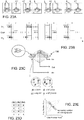
- a within-well high-throughput printing method is performed as depicted in FIGs. 8A -8C .
- this method in contrast to the "inverted" approach illustrated in and described above with reference to FIGs. 2A-2C , the pre-polymer solution is not isolated completely within the target substrate.
- the image is projected such that it is in focus at the distal end of the optical assembly 82 (in this embodiment, focusing lens 88, collimating lens 89, and window 91), where window 91 (formed from a transparent material such as sapphire, glass, PDMS or other appropriate material) forms a hermetic seal that can be immersed within a well 80a (as shown) of multi-well plate 80 containing the pre-polymer.
- window 91 formed from a transparent material such as sapphire, glass, PDMS or other appropriate material
- multi-well plate 80 is shown with wells 80a - 80x, however, any number of wells may be used.
- Pre-polymer A Pre-polymer A
- Pre-polymer B Pre-polymer B
- a variety of different combinations of pre-polymers may be used to achieve the desired properties within the scaffold, as will be described further below.
- FIG. 8C which diagrammatically illustrates "snapshots" of the printing process at times t 1 , t 2 and t 3 , as the substrate/stage 92 supporting plate 80 and its wells is pulled away from the stationary window 91, fresh pre-polymer solution is drawn into the widening gap via capillary action.
- This process occurs in a continuous fashion as the stage 92 is translated smoothly across the desired height of the scaffold 86 and results in the most recently printed layer being closest to the printing interface 90, thus defining the "polymerization plane". While described in the terms of "layers", the printing process is actually continuous, such that the layers can also be thought of as "slices" through a continuous structure.
- FIG. 8C diagrammatically shows the location of the polymerization plane z 1 at time t 1 , when "layer 50" is printed.
- the inset corresponding to time ti/layer 50 shows the current digital mask projected from the DMD 84.
- the center portion of FIG. 8C shows the location of the polymerization plane z 2 at time t 2 , at which time "layer 100" is printed.
- the inset corresponding to time t 2 shows the current digital mask projected from the DMD 84.
- the right hand portion of FIG. 8C shows the location of the polymerization plane z 3 at time t 3 , at which time "layer 161" is printed.
- the inset corresponding to time t 3 shows the current digital mask projected from the DMD.
- the projected light is not transmitted through previously printed layers to print subsequent layers as is done in the "inverted” method described above.
- This approach allows for printing of much taller structures in addition to the creation of structures with fully enclosed features. This contrasts with attempts to print enclosed cavities or channels using the "inverted” method, which often lead to undesired polymerization in these "void” areas due to the light necessarily passing through these regions to print subsequent layers. Nonetheless the "inverted” method can provide added utility when combined with this immersion-based approach, as one method can be used to fabricate a subcomponent of the complete scaffold using one type of material while the other method can be used subsequently to print different materials within the same scaffold.
- FIG. 9A is a screenshot of the CAD software used to design and render two different 3D models - an open-sided cube (left) and a fenestrated cylinder (right).
- the printing was carried out on a standard microscope slide with a PDMS gasket placed on top of the slide to define a well to contain the pre-polymer solution.
- the final printed hydrogels (formed of PEGDA) are shown in FIG. 9B , clearly reflecting the desired morphology determined by the CAD design shown in FIG. 9A .
- the target glass substrate may be chemically modified to promote cross-linked covalent bonding of the printed structure with the slide or glass-bottomed well plate.
- methacrylation is used.
- the optical window may also be surface-treated to render it hydrophobic. Issues relating to window adhesion may also be partially mitigated by the continuous fabrication technique itself, which has the advantage that the substrate does not dwell statically at the print interface, which occurs with conventional layer-by-layer printing.
- the continuous motion of the stage in synchrony with the dynamic projection mechanism not only allows for "layerless” printing but also offers the ability for hierarchical nanopatterning and/or micropatterning of the printed material.
- subregions within the macroscale structure can be "sub-patterned" with different sequences of spatiotemporal light modulation.
- a slab or cube structure as in FIGs. 10A and 10B could be printed either by continuous exposure of the same projected square by a steady consistent intensity of light or by intermittently pulsing the intensity of the light.
- the flux of photons available to initiate free-radical polymerization at a particular pixel location can be variable.
- FIG. 10A shows a theoretical rendering of the internal structure of a simple cube as a result of varied subpatterns of light exposure.
- the light was modulated in a checkerboard fashion as a function of a voxel's distance from the cube's surface: larger checkerboards were used for more internal portions of the cube vs. smaller sizes for regions of the cube closer to the surface.
- the magnified images in the lower panels, below the overall view, in FIG. 10A also demonstrate how this subpatterning of light can interact with pre-polymer solutions of different properties in terms of material characteristics such as polymerization efficiencies, macromer concentrations, and molecular weights, among others. This could yield finer detailed structures or alternatively result in more diffuse internal patterning.
- FIG. 10B illustrates, the same exposure pattern (top image) could theoretically result in different internal morphologies (shown in the center and lower images of FIG. 10B ), depending on the material used.
- FIGs. 11 and 12 provide examples of the same patterning algorithm, e.g., varying checkerboards, applied to more complex shapes, e.g., a toroid.
- This subpatterning can be applied to complex macroscale structures to locally modulate porosity and diffusivity.
- One approach may be to increase pore sizes for more internal deeper regions to counteract low diffusion rates, thus "normalizing" diffusivity throughout the bulk structure.
- the subpatterning technique can be applied as illustrated in the biomimetic examples presented in FIGs. 13A -13C , showing a rat brain ( FIG. 13A - CAD design) and possible subpatterning arrangements at different "layers” or “slices” ( FIGs. 13B and 13C ), and a human lower limb model ( FIG. 14 ).
- the L3PDOP platform described above yields two powerful modes of operation, which are diagrammatically illustrated in FIG. 7 .
- the first modality 72 provides for 3D microscale bioprinting of biological substrates via dynamic stereolithography.
- the second modality 74 provides for optogenetic control of neurons with high spatiotemporal resolution.
- Stereolithographic 3D bioprinting (mode 72) using the printing platform described with reference to FIG. 1A and FIGs. 2A-2C provides for photopolymerization of multiple biocompatible materials (e.g., PEGDA, MeHA, GelMA) and facilitates cell encapsulation within these structures. Additionally, these materials - along with their incorporated cell types - can be used heterogeneously in the same scaffold to provide 3D patterned co-culture substrates, thus facilitating the study of neuronal/glial interactions.
- biocompatible materials e.g., PEGDA, MeHA, GelMA
- the platform is capable of functioning not only in the fabrication and optogenetic stimulation modalities but also for recording network activity across multiple domains: 1) multi-electrode arrays (MEAs) - on which the 3D neuron network structures are printed - allow orthogonal recording of electrical activity concurrent with optogenetic stimulation; and 2) fluorescent imaging of voltage-sensitive dyes and proteins can be simultaneously performed using the same or similar light source utilized for bioprinting, thereby enhancing the single-neuron resolution of network activity.
- MEAs multi-electrode arrays
- fluorescent imaging of voltage-sensitive dyes and proteins can be simultaneously performed using the same or similar light source utilized for bioprinting, thereby enhancing the single-neuron resolution of network activity.
- the objective is the creation of a brain on a chip platform that integrates 3D heterogeneous neural cultures, optogenetics-enabled high-resolution stimulation, and parallel electrical and image-based recording of neural activity.
- the fabrication methods utilized in this platform offer control over both the topographical complexity and the cellular and material composition of the neural environment, thereby allowing for the potential for systematically-controlled increases in complexity.
- Example 2 Neural clusters from iPSCs
- the L3PDOP platform finds myriad applications in fundamental neuroscience research, clinical diagnostics, screening of novel drug candidates, and comparative investigations of artificial versus biological neural networks in conjunction with neuromorphic hardware (e.g. "brain-on-a-chip” devices).
- the printing technique enables facile, rapid fabrication of 3D hydrogels that support the culture of iPSC-derived neurons with the following capabilities: 1) 3D patterning of hydrogel microenvironments via dynamic optical stereolithography for high-throughput scaffold fabrication that is co-registered with MEAs at high precision; 2) directed arrangement of neural clusters and modulation of cell alignment, growth, and connectivity via hydrogel composition, geometry, and dimensions; 3) support for functional connectivity as demonstrated by positive expression of associated biomolecular markers, and 4) spontaneous electrical activity during long-term culture of neural populations that corresponds with their spatial arrangement on the 3D printed hydrogel-MEA substrates.
- Stereolithographic 3D bioprinting as described herein allows for photopolymerization of multiple biocompatible materials.
- materials include gelatin methacrylate (GelMA), methacrylated hyaluronic acid (MeHA), poly(ethylene) glycol diacrylate (PEGDA)).
- the printing method also facilitates cell encapsulation within these structures.
- Other classes of specialized photo-crosslinkable polymers can include conductive polymers, such as PANI-PAAMPSA [polyaniline-poly(2-acrylamido-2-methylpropane sulfonic acid)]. (See, e.g., Yoo, J. E.
- NPCs neural progenitor cells
- hydrogels were made using photopolymerizable macromer solutions of 5 to 7.5% gelatin methacrylate (GelMA) in DPBS.
- GelMA gelatin methacrylate
- the GelMA hydrogel scaffolds were used for culture and patterning of iPSC-derived NPCs. UV-light mediated polymerization occurred within 30 to 60 seconds of patterned exposure to produce scaffolds 5mm x 3mm x 100 to 500 ⁇ m.
- NPCs When seeded, NPCs aggregated within the wells and extended neurites along the guidance channels to varying degrees depending on the water content of the material. Percent concentration of GelMA (5% vs. 7%) had a substantial effect on cell spreading, proliferation, alignment, and connectivity ( FIG. 16 ). After one month of culture, scaffolds were fixed in 4% paraformaldehyde, and immunofluorescently labeled using antibodies for synapsin, VGlut1, MAP2, GFAP, and beta-III tubulin to assess cell morphology, function, and synaptic connectivity. As shown in FIG.
- markers of functional connectivity exhibited differences based on substrate type and patterning dimensions, with higher levels of synapsin expression observed in cultures on the GelMA substrate when compared to the glass control. Sparse expression of VGlut1 was also observed, suggesting early commitment of some neurons to a glutamatergic phenotype.
- FIG. 18 To further assess functional connectivity, neurons were transfected with plasmid DNA for co-expression of wheat germ agglutinin (WGA) and green fluorescent protein (GFP) reporter ( FIG. 18 ). Neurons staining positive for WGA but negative for GFP suggest that post-synaptic uptake of WGA has occurred through functional connections between WGA-expressing and non-expressing populations. Furthermore, synapsin expression was additionally assessed via a plasmid for co-expression of GFP that is localized with synapsin expression ( FIG. 19 ). As discussed previously, greater expression is seen in the 3D scaffold conditions (lower panel) versus the glass control (upper panel).
- WGA wheat germ agglutinin
- GFP green fluorescent protein
- the patterned neuronal networks also demonstrated spontaneous, spatially-dependent electrical activity.
- the MEA electrode locations that corresponded with the center of the neural clusters within the hydrogel wells exhibited the highest activity.
- channel 20 (3 rd row, 8 th column in the zoomed in segment of FIG. 20A ) corresponds with the center of the large well cluster in the upper right corner of the MEA 200 ( FIG. 20A ) and shows high activity compared to other channels (e.g., highlighted channels 12 and 19) that are nearby but in sparsely populated areas ( FIG. 20B ).
- Subplots of the spiking activity shown at shorter time scales demonstrate wave profiles that are characteristic of local field potentials. This is consistent with the setup of a hydrogel placed on top of the MEA and reflects the integrated activity in the well region.
- Example 3 Integration with 3D-printed conductive polymer electrodes
- FIGs. 21A and 21B illustrate one possible spatial arrangement and varying electrode lengths, respectively.
- FIG. 21A shows a simple grid-like array in MEA 210, with uniformly spaced rows and columns of flat electrodes of similar heights, while FIG. 21B illustrates electrodes 212A n of different lengths (heights) extending from the same grid.
- different geometrical layouts and varying electrode heights can be constructed by selection of appropriate printing patterns, conditions, and materials.
- 3D-printed conductive hydrogel electrodes can probe the network internally at various spatial locations throughout the neuron-laden scaffold.
- the conductive polymer electrodes can provide a conduit for electrical neurostimulation in a modality that is orthogonal to the optogenetically-mediated stimulation and thus can be independently and/or simultaneously applied. This can enable investigation of the effects of long-term potentiation (LTP) or long-term depression (LTD) within neuronal subpopulation in terms of the network's response to concurrent activation via the alternate stimulation modality.
- LTP long-term potentiation
- LTD long-term depression
- Example 4 Adaptive, reprogrammable biological logic gates, perceptrons, and hybrid neural networks
- a synthetic analogue to neural computation exhibits far greater performance in tasks such as visual identification and speech recognition.
- software algorithms e.g., artificial neural networks
- hardware implementations of neural circuits e.g., neuromorphic hardware
- neural circuits e.g., neuromorphic hardware
- These technologies have been widely applied towards solving computationally intensive problems, such as data mining, automated medical diagnosis, and self-learned game strategies, as well as to reveal the potential mechanisms that underlie the various dimensions of human cognition.
- the integrated neural fabrication platform described herein can provide techniques for bridging this gap and for developing novel hybrid artificial/biological neural network devices that may yield computational power not yet realized by either synthetic or natural versions of these networks in isolation.
- a biological neural network created using the invention described herein is a logic gate consisting of two input nodes 221, 222, one output node 223, and two channels 224 (i.e., edges, per graph theory) between each of the input nodes and the output node, as shown in FIG. 22A .
- each node contains a neural population comprising a number of neurons (n ⁇ 1) of various types, including neurons that are optogenetically modified with light-responsive ion channels, e.g., channelrhodopsin-2 (ChR2) (sensitive to blue light) or halorhodopsin (sensitive to green/yellow light) to enable light-mediated depolarization or hyperpolarization, respectively, as appropriate.
- ChR2 channelrhodopsin-2
- halorhodopsin sensitive to green/yellow light
- ChR2 + and wild type ChR2 - are used. Each channel can guide neurite connections from one node to another.
- the synaptic connectivity of this simple neural network can be employed to entrain a designated output in response to provided inputs, e.g., a classic AND logic gate.
- the corresponding truth table for the AND gate is provided in FIG. 22D.
- FIG. 22C and 22E illustrate an exemplary training protocol, which can be specified in terms of stimulus modality (e.g., optical or electrical), stimulus duration, input-to-output stimulus latency, stimulus strength, number of trials, inter-trial interval, etc., with a set number of trials defining a training epoch.
- stimulus modality e.g., optical or electrical
- the three rows of variously spaced vertical bars in FIG. 22C represent the spike raster plots generated by the three nodes throughout an example training protocol, with the top and bottom rows representing the input nodes and the middle row representing the output node.
- the horizontal lines that span above some subsets of vertical bars represent the periods during which light stimulation was active for that particular node.
- Arrows drawn from FIG. 22C to 22E indicate the different training conditions.
- the biological neural network may alter its connectivity via purported Hebbian learning principles (i.e., synaptic plasticity), such as spike-timing dependent plasticity.
- the logic gate may be subsequently retrained using a new truth table to convert the network into a different logic gate type, e.g., converting it from an AND gate to an exclusive-OR (XOR) gate, in which the output will be "1" if and only if one input is “1" ( FIG. 23D ).
- the XOR gate training sequence is illustrated in FIGs. 23A (showing the MEAs) and 23B (showing the corresponding spike raster plots and associated periods of light stimulation), using blue (“B”) and green/yellow (“G/Y”) light.
- FIG. 23A shows the MEAs
- 23B shows the corresponding spike raster plots and associated periods of light stimulation
- B blue
- G/Y green/yellow
- the MEA 230 is printed to include neurons modified with channelrhodopsin (ChR2) and halorhodopsin (NpHR) to provide depolarization/excitation and hyperpolarization/inhibition, respectively, in response to different colors of light, along with populations of wildtype ("WT", i.e., not light activated) excitatory and inhibitory neurons, e.g., glutamatergic ("Glut”) and GABAergic (“GABA”) neurons, at varying ratios within each node.
- WT wildtype
- Glut glutamatergic
- GABA GABAergic
- an entrained logic gate can be tested to determine the robustness of its output in relation to the desired truth table ( FIG. 23D ), and its performance can be quantitatively described, e. g., using a receiver operating characteristic (ROC) curve ( FIG. 23E ).
- ROC receiver operating characteristic
- the biological neural network can be constructed to contain multiple numbers of inputs, outputs, and interconnections, along with multiple intermediary layers of nodes that ultimately link the input layer to the output layer.
- the biological neural network may resemble artificial neural network models, e.g., a perceptron.
- a perceptron structure 240 is shown in abstracted form in FIG. 24A , with input 242, middle 244 and output layers 246 (connected by connectors 248) constructed using the same modified neurons used in the prior example: channelrhodopsin (ChR2 + ) and halorhodopsin (NpHR + ), plus wild-type glutamatergic (Glut) and wild-type GABAergic (GABA) neurons.
- 24B diagrammatically illustrates the MEA plate 240a imprinted with neuron-laden hydrogels using the 3D printing platform to implement biological perceptron 240, with corresponding input 242a, middle 244a and output 246a layers.
- the multi-branched grid 248a connecting the nodes of the three layers represents guidance channels printed within the hydrogel to facilitate interconnectivity as would be realized in a physical implementation of the abstracted illustration in FIG. 24A .
- This biological perceptron can be compared to its synthetic equivalent to determine the degree of correspondence between the in vitro and in silico implementations.
- the parameters of the nodes can be tuned by defining the geometry of the scaffold during fabrication.
- Nodes and connecting channels can be modulated in physical terms, including but not limited to diameter, eccentricity, internode distance, channel width, and channel radius of curvature.
- the nodes and connecting channels can also be modulated in biochemical terms, including but not limited to hydrogel composition, concentration, functionalization with bioactive moieties, localized delivery of bioactive molecules, and light-triggered release of bioactive molecules.
- the activating columns of light 249a-c as differentiated by differences in hue and opacity within the schematic, represent the modulation possible in terms of the light stimulus, including but not limited to intensity, duration, wavelength, number of pulses, and pulse width.
- the network may contain, for example, redundant channels or nodes of different shapes. Comparison to computational simulations of neural networks that include the relative spatial arrangement of the constituent neurons as a defining parameter in their models may further elucidate how spatial 3D patterning of neurons can influence the circuit behavior.
- neurostimulation can be provided either optically by projecting light onto optogenetically-modified neurons or electrically via the MEA interface.
- the neurons can be modified to yield populations that express different light-sensitive opsins to elicit varied electrical responses, e.g., channelrhodopsin-2 (ChR2) for depolarization/excitation versus halorhodopsin (NpHR) for hyperpolarization/inhibition.
- ChR2 channelrhodopsin-2
- NpHR halorhodopsin
- heterogeneous populations of wildtype excitatory and inhibitory neurons e.g., glutamatergic and GABAergic neurons at varying ratios within each node, as well as any of the myriad interneuron species either found in native tissue or synthetically engineered to exhibit more exotic or not naturally-realized behaviors
- the neurons may undergo optogenetic modification either before or after incorporation into the 3D scaffold.
- the scaffold material may be functionalized via 3D patterning to allow for localized transfection of plasmids encoding different opsins per a defined spatial arrangement.
- these scaffold, network, and stimulus parameters can be modulated in conjunction with other environmental changes, such as light-activated uncaging of neurotransmitters and administration of other mechanical, chemical, and/or biological stimuli that may influence the network's training efficiency, robustness, and overall dynamics.
- assessing the long-term fidelity of the entrained biological neural network can provide information regarding its capacity to serve as a long-term biological substrate for memory.
- a multi-well MEA plate or multi-chambered MEA microscope slide consisting of several in vitro biological neural networks may be kept in culture for an extended period per standard cell culture protocols.
- the fidelity of the networks' entrained response can be quantified to determine longevity or volatility of the entrained response, i.e. the persistence of the embedded memory.
- This non-von Neumann model of integrated memory and computation serves the basis for many theoretical frameworks of human cognition and has recently been implemented in the context of hybrid CMOS-memristor neuromorphic circuits.
- each well 252a of a multi-well plate 254 (seen in FIG. 25B ) can be entrained with a unique perceptron 250 to perform a specified subtask in response to different stimuli, e.g., illumination.
- FIG. 25A which illustrates a single exemplary perceptron 250, in an identification task where the color and character of a letter must be computed for example, a blue "A", one well 252a in FIG.
- Multi-well optical stimulation may be achieved through concurrent projection of multiple DMDs 256 or by using a mirror galvanometer to rapidly scan across multiple wells. Generally, this approach is akin to the modern implementation of multi-core CPUs to achieve parallel processing.
- an integrated computer processor 258 and accompanying algorithm may be used to implement more sophisticated computational capabilities, including but not limited to 1) a closed-loop feedback system where output provided by biological perceptrons can trigger changes in the illumination pattern projected by the DMD 256, or 2) output from the biological perceptrons providing input into an artificial perceptron or neural network implemented within the computer to create a hybrid biological-artificial neural network.
- the biological neural networks can be entrained to respond to more dynamic stimuli, for example, to self-learn video game strategies much in the way that artificial neural networks have been designed to self-learn these types of tasks, for example, using Google® DeepMindTM.
- Google® DeepMindTM See, e.g., V. Mnih et al., "Human-level control through deep reinforcement learning", Nature 518, 529-533 (2015 ).
- a densely-patterned neural network of optogenetically modified neurons can be entrained by projecting the video feed from a game, such as the classic video game PONG®.
- the projected frames of the video game can entrain the network to "predict" the trajectory of a ball and thus provide output to direct the movement of the paddle at the end of the board.
- the biological neural network may self-learn the optimal placement of the paddle to score a point. This entraining process may be enhanced by the concurrent administration of biochemical, e.g., dopamine, or other stimuli that strengthen the synaptic connections formed during a successful network response.
- biochemical e.g., dopamine
- the application of these large-scale self-learning biological neural networks may serve to recapitulate the intertwined memory and computational mechanisms of the human visual system.
- the incorporation of high-density 3D recording via the integrated printing of conductive polymer electrodes enables measurement of network dynamics in the proper spatial context, while using soft biocompatible hydrogels that feature mechanical properties that are closer to those of tissue in vivo.
- the 3D patterning approach presented herein can be applied towards creating compartmentalized and/or systematically reduced representations of canonical in vivo neural systems. These in vitro constructs could then be used to assess the functional significance of various system components in a more accessible form to determine, for example, the individual and collective contributions of neural subpopulations in higher-level cognition and behavior.
- iPSCs induced pluripotent stem cells
- 3D culture environments resembling the native milieu in terms of biomaterial composition and mechanochemical properties can lead to neural cultures that correspond more closely with native systems and thus provide improved clinical relevance. Emerging evidence suggests that when compared to 2D substrates generated using conventional cell-culture arrangements such as Petri dishes, 3D microenvironments consisting of biocompatible hydrogels aid cells in more accurately portraying a diseased neural state (See, for example, S. H. Choi et al., "A three-dimensional human neural cell culture model of Alzheimer's disease," Nature 515, 274-278 (2014 )).
- challenges remain in systematically patterning and probing 3D neural cultures to elucidate relationships between collective cell physiology and emergent electrical behavior.
- Multi-electrode arrays (MEAs) and voltage-sensitive fluorescent imaging, as well as optogenetic tools for stimulating neurons via light are well-established techniques for recording neural activity in response to stimulation, but their application to in vitro 3D systems has been limited.
- the integrated platform for 3D bioprinting, optoelectric stimulation/recording, and fluorescence imaging is applied towards the construction and interrogation of in vitro neural disease models.
- the projection printing technology facilitates both the rapid 3D printing of neuron-laden hydrogels directly onto multi-well MEAs, including the MEDTM Probe available from Alpha MED Scientific, Inc. (Berkeley, CA, US) and the M768-KAPTM series available from Axion BioSystems (Atlanta, GA, US), and the subsequent optical stimulation of these constructs at high spatiotemporal resolutions with precise registration between the stimulation pattern and the previously printed 3D geometries.
- optical 3D printing techniques enables the incorporation of complex topographies, composite biomaterials/nanomaterials, and heterogeneous cell populations with higher throughput when compared to inkjet-based 3D bioprinting, and with the inherent capability for optogenetic stimulation that is multiplexed with concurrent electrical recording and voltage-sensitive imaging.
- the ability to control the 3D arrangement, functional connectivity, and dynamic activation provides systematic assess to in vitro representations of neural circuits across both normal and diseased states. These approaches can help to elucidate causal relationships between pathological phenotypes and the anomalous network dynamics involved in neurological impairment.
- a connectivity model featuring two nodes connected by a single channel may be constructed, wherein a node of a certain diameter contains a neural cluster of a correspondingly proportional number of neurons and the distance between the two nodes is modulated to influence the degree of connectivity between the two nodes.
- the level of connectivity between the two nodes can be quantified in terms of morphological arrangements (e.g., number of synapses per neuron) and functional activity (e.g., cross-correlated spiking/burst activity).
- Other embodiments may include multiple nodes, additional channels per node, and variations in node-channel geometry and topological arrangement. Comparisons between normal and diseased neural populations in terms of these quantitative measures may provide a diagnostic benchmark for assessing disease prognosis.
- Standardized metrics for connectivity can be assessed in a high-throughput fashion in multi-well MEAs that feature replicates of the same normal versus diseased neural constructs. These multi-well systems with incorporated highly-parallelized 3D printed neural circuits can be used for screening of drug candidates in the development of pharmaceutical treatments for neurological disorders.
- FIGs. 26A and 26B illustrate examples of custom MEA patterning capability enabled by the 3D printing platform for use in high-throughput screening of parallel samples. Moreover, assessment of efficacy and safety of potential medications can be performed with patient-level specificity through the use of patient-specific iPSC-derived neural populations.
- Example 6 Cloud-based 3D bioprinting and neurostimulation platform
- Three-dimensional cell culture within biomaterial scaffolds has evolved to incorporate numerous aspects of the native tissue microenvironment, such as topographic patterning, heterogeneous co-culture populations, and dynamic modulation of scaffold properties. Yet, despite the novel avenues of investigation they provide, newer 3D approaches have seen limited use by the broader life sciences. Barriers include the knowledge base and capital investment required for implementing complex custom equipment. Research collaborations help overcome these hurdles via sharing of resources, but such efforts are often met with challenges in communication and efficiency as well as physical bottlenecks in long-distance sample and reagent transfer. Teams can often struggle to remain abreast of experimental details for project components outsourced to a collaborating lab. In the context of 3D bioprinting, a disconnect between one lab's design requirements and another lab's technical capabilities can lead to inefficient cycles of revision and rework, with an increased likelihood for experimental error, loss of data integrity, and misinterpretation of results.
- a web application framework can be used to extend the collaborative capacity of the integrated bioprinting, optical projection, and neurostimulation platform presented herein (or of other 3D printing platforms in general).
- This framework uses a "cloud-based" solution for current and future collaborators by providing:
- the foregoing disclosure provides novel approaches in both complex 3D biofabrication and dynamic molecular biosensing towards the investigation of poorly understood cell-cell interactions among heterogeneous cell populations.
- the 3D bioprinting platform of the present invention offers a transformational machine for creating biomimetic, functional tissues.
- the biosensors and single cell imaging should provide powerful tools to study molecular coordination in space and time in live cells.
- the integration of biosensing techniques of high sensitivity/specificity with 3D biomimetic tissue scaffolds will enable high-resolution monitoring of the dynamics of proteins, enzymes, subcellular organelles, and electrical activity in precisely engineered physical/chemical microenvironment.
- the technical impact of the micro-tissue-on-a-chip model lies in its immediate applications for early drug screening and personalized medicine.
Landscapes
- Engineering & Computer Science (AREA)
- Chemical & Material Sciences (AREA)
- Health & Medical Sciences (AREA)
- Materials Engineering (AREA)
- Manufacturing & Machinery (AREA)
- Physics & Mathematics (AREA)
- Life Sciences & Earth Sciences (AREA)
- Toxicology (AREA)
- Biomedical Technology (AREA)
- Mechanical Engineering (AREA)
- Optics & Photonics (AREA)
- Immunology (AREA)
- Urology & Nephrology (AREA)
- Molecular Biology (AREA)
- Hematology (AREA)
- Oral & Maxillofacial Surgery (AREA)
- Thermal Sciences (AREA)
- Cell Biology (AREA)
- Food Science & Technology (AREA)
- Medicinal Chemistry (AREA)
- Tropical Medicine & Parasitology (AREA)
- Microbiology (AREA)
- Bioinformatics & Cheminformatics (AREA)
- Pathology (AREA)
- General Physics & Mathematics (AREA)
- Biotechnology (AREA)
- Analytical Chemistry (AREA)
- Biochemistry (AREA)
- General Health & Medical Sciences (AREA)
- Electromagnetism (AREA)
- Microelectronics & Electronic Packaging (AREA)
- Neurology (AREA)
- Neurosurgery (AREA)
- Apparatus Associated With Microorganisms And Enzymes (AREA)
Claims (12)
- Système pour la microfabrication 3D d'une structure, comprenant :une source de lumière (10 ; 110) configurée pour projeter de la lumière à l'intérieur d'un chemin optique, la source de lumière émettant de la lumière à une longueur d'onde configurée pour initier une photopolymérisation ;un modulateur spatial de lumière (13 ; 84 ; 113) disposé à l'intérieur du chemin optique et configuré pour moduler la lumière issue de la source de lumière en réponse à un ensemble de masques numériques (11 ; 111) correspondant à des couches de la structure ;une optique de projection (14 ; 82 ; 114) configurée pour focaliser la lumière modulée sur un plan optique (120) ;une platine (15 ; 92 ; 115) supportant un substrat comprenant un réseau de puits (80), chaque puits dans le réseau de puits (80) rempli avec un matériau photopolymérisable (124) à l'intérieur du plan optique, la platine étant configurée pour se déplacer le long d'au moins un axe ;une fenêtre transparente (91) configurée pour entrer en contact avec le matériau photopolymérisable (124), une interface (90) entre la fenêtre (91) et le matériau photopolymérisable (124) coïncidant sensiblement avec le plan optique (120) ; etun processeur informatique (12) configuré pour :contrôler le modulateur spatial de lumière (13 ; 84 ; 113) pour projeter une séquence d'images correspondant à l'ensemble de masques numériques (11 ; 111) à l'intérieur d'un ou plusieurs puits du réseau de puits (80) ; etcoordonner le déplacement de la platine (15 ; 92 ; 115) pour déplacer en continu une position du plan optique (120) à l'intérieur du matériau photopolymérisable (124) pour projeter successivement chaque image de la séquence pour générer une structure sans couche à l'intérieur du ou des puits en photopolymérisant de façon continue et progressive le matériau photopolymérisable (124) le long de l'au moins un axe.
- Système de la revendication 1, dans lequel le modulateur spatial de lumière (13 ; 84 ; 113) comprend un dispositif de micromiroirs numériques.
- Système de la revendication 1, dans lequel le matériau photopolymérisable est une solution de prépolymère, au moins une partie des puits dans le réseau de puits (80) contenant différentes solutions de prépolymère.
- Système de la revendication 1, dans lequel la fenêtre (91) est scellée sur une extrémité d'un tube pour immersion dans la solution de prépolymère (124) et la platine est éloignée du plan optique (120) le long d'un axe Z de telle sorte que des couches successives sont polymérisées au-dessus de couches polymérisées auparavant.
- Système de la revendication 4, dans lequel un éloignement de la platine du plan optique (120) conduit une quantité supplémentaire de solution de prépolymère à être tirée vers le plan optique.
- Système de la revendication 1, dans lequel le substrat comprend en outre une électrode (212) ou un réseau multi-électrode (210 ; 230 ; 240).
- Système de la revendication 1, dans lequel le matériau photopolymérisable comprend un polymère conducteur et au moins une partie de la séquence d'images correspond à des structures d'interconnexion alignées avec une ou plusieurs électrodes.
- Système de la revendication 1, comprenant en outre une deuxième source de lumière (74) disposée à l'intérieur du chemin optique, la deuxième source de lumière émettant de la lumière à une longueur d'onde configurée pour stimuler un matériau biologique photoactif.
- Système de la revendication 1, comprenant en outre un dispositif d'acquisition d'images disposé à l'intérieur du chemin optique.
- Système de la revendication 1, dans lequel au moins une partie des masques numériques (11 ; 111) conduisent le modulateur spatial de lumière (13 ; 84 ; 113) à générer des sous-motifs à l'intérieur de couches sélectionnées de la structure.
- Système de la revendication 1, dans lequel la platine (15 ; 92 ; 115) est mobile le long d'axes X, Y et Z.
- Procédé pour la microfabrication 3D d'une structure sans couche utilisant le système (100) de l'une quelconque ou plusieurs des revendications 1 à 11.
Applications Claiming Priority (2)
| Application Number | Priority Date | Filing Date | Title |
|---|---|---|---|
| US201462001025P | 2014-05-20 | 2014-05-20 | |
| PCT/US2015/031848 WO2015179572A1 (fr) | 2014-05-20 | 2015-05-20 | Bio-impression sans formation de couches par projection optique dynamique et ses utilisations |
Publications (3)
| Publication Number | Publication Date |
|---|---|
| EP3145689A1 EP3145689A1 (fr) | 2017-03-29 |
| EP3145689A4 EP3145689A4 (fr) | 2018-01-24 |
| EP3145689B1 true EP3145689B1 (fr) | 2020-01-01 |
Family
ID=54554728
Family Applications (1)
| Application Number | Title | Priority Date | Filing Date |
|---|---|---|---|
| EP15795499.1A Active EP3145689B1 (fr) | 2014-05-20 | 2015-05-20 | Bio-impression sans formation de couches par projection optique dynamique et ses utilisations |
Country Status (5)
| Country | Link |
|---|---|
| US (2) | US10464307B2 (fr) |
| EP (1) | EP3145689B1 (fr) |
| CN (2) | CN106660236B (fr) |
| CA (1) | CA2952595C (fr) |
| WO (1) | WO2015179572A1 (fr) |
Cited By (1)
| Publication number | Priority date | Publication date | Assignee | Title |
|---|---|---|---|---|
| US11554370B2 (en) | 2021-01-08 | 2023-01-17 | Cellanome, Inc. | Devices and methods for analyzing biological samples |
Families Citing this family (44)
| Publication number | Priority date | Publication date | Assignee | Title |
|---|---|---|---|---|
| US11369465B2 (en) | 2013-01-14 | 2022-06-28 | Scripps Health | Tissue array printing |
| WO2016191331A1 (fr) * | 2015-05-22 | 2016-12-01 | Hermo Medical Solutions, S.L. | Procédés de fabrication d'appareil d'immobilisation |
| EP3344443B1 (fr) | 2016-01-20 | 2022-03-02 | Hewlett-Packard Development Company, L.P. | Dispositif d'impression et procede d'impression |
| CN107229189A (zh) * | 2016-03-23 | 2017-10-03 | 中国科学院沈阳自动化研究所 | 基于dmd的动态掩模的水凝胶微柱阵列的快速制作方法 |
| JP2019520865A (ja) * | 2016-05-26 | 2019-07-25 | スクリップス ヘルス | 組織欠損を修復するためのシステムおよび方法 |
| WO2018009943A2 (fr) | 2016-07-08 | 2018-01-11 | Cypre, Inc. | Appareil pour le façonnage d'hydrogels dans des plaques multipuits |
| US10773510B2 (en) | 2017-02-06 | 2020-09-15 | 3D Systems, Inc. | Scalable and fast three dimensional printing system |
| US11085018B2 (en) | 2017-03-10 | 2021-08-10 | Prellis Biologics, Inc. | Three-dimensional printed organs, devices, and matrices |
| US10933579B2 (en) * | 2017-03-10 | 2021-03-02 | Prellis Biologics, Inc. | Methods and systems for printing biological material |
| ES2870775T3 (es) * | 2017-03-22 | 2021-10-27 | Alcon Inc | Impresión 3D de una lente intraocular que tiene superficies curvas suaves |
| US20210108098A1 (en) * | 2017-04-25 | 2021-04-15 | Paul Gatenholm | Preparation and applications of biocompatible conductive inks based on cellulose nanofibrils for 3d printing of conductive biomedical devices and for use as models for study of neurodegenerative disorders and connection between brain/neurons and communication or other electronic devices |
| JP2020524483A (ja) | 2017-05-25 | 2020-08-20 | プレリス バイオロジクス,インク. | 三次元印刷された器官、デバイス、およびマトリックス |
| CN107175823B (zh) * | 2017-06-09 | 2019-03-08 | 中国科学院上海光学精密机械研究所 | 多分辨率飞秒激光3d打印装置和打印方法 |
| US11499130B2 (en) | 2017-10-10 | 2022-11-15 | Cypre, Inc. | Methods and devices for cell culture |
| EP3697340A4 (fr) * | 2017-10-20 | 2021-08-04 | Indiana University Research & Technology Corporation | Bio-impression 3d de cellules porcines sans échafaudage |
| EP3704545A4 (fr) * | 2017-10-31 | 2021-06-16 | Lawrence Livermore National Security, LLC | Système et procédé de polymérisation biphotonique parallèle à résolution en profondeur destinés à la fabrication additive submicronique extensible |
| WO2019103970A2 (fr) | 2017-11-21 | 2019-05-31 | Cypre, Inc. | Masque de génération de caractéristiques dans une plaque de micropuits |
| EP3732027A4 (fr) | 2017-12-29 | 2021-04-14 | Lawrence Livermore National Security, LLC | Système et procédé de fabrication additive sous-micron |
| AU2019254043B2 (en) * | 2018-04-17 | 2024-12-05 | Alcon Inc. | Making an implant for an eye |
| WO2020028436A1 (fr) | 2018-07-31 | 2020-02-06 | Prellis Biologics, Inc. | Auto-encapsulation optiquement induite |
| CN109093821A (zh) * | 2018-09-04 | 2018-12-28 | 南京农业大学 | 一种室温挤出复杂结构件坯体的成形装置 |
| JP2022506523A (ja) | 2018-11-02 | 2022-01-17 | インクビット, エルエルシー | インテリジェント付加製造方法 |
| US11354466B1 (en) | 2018-11-02 | 2022-06-07 | Inkbit, LLC | Machine learning for additive manufacturing |
| US11651188B1 (en) * | 2018-11-21 | 2023-05-16 | CCLabs Pty Ltd | Biological computing platform |
| AU2020205973A1 (en) * | 2019-01-08 | 2021-07-15 | Inkbit, LLC | Reconstruction of surfaces for additive manufacturing |
| WO2020146490A1 (fr) | 2019-01-08 | 2020-07-16 | Inkbit, LLC | Reconstruction de profondeur dans la fabrication additive |
| CN109822891B (zh) * | 2019-03-13 | 2023-09-08 | 重庆摩方科技有限公司 | 一种高精度大幅面立体投影3d打印系统及其打印方法 |
| WO2020210681A1 (fr) | 2019-04-11 | 2020-10-15 | Allegro 3D, Inc. | Procédé et appareil pour la fabrication sans masque à haut débit d'échafaudages en polymère et de tissus biologiques dans des plaques à plusieurs puits |
| CN112334839B (zh) | 2019-05-30 | 2023-10-31 | 埃斯科绘图成像有限责任公司 | 自动测量光聚合物印刷版密度的处理和装置 |
| CN110239087B (zh) * | 2019-06-04 | 2021-03-30 | 浙江大学 | 一种基于成像原理的3d打印设备 |
| US11898135B1 (en) | 2019-07-01 | 2024-02-13 | CCLabs Pty Ltd | Closed-loop perfusion circuit for cell and tissue cultures |
| US11712837B2 (en) | 2019-11-01 | 2023-08-01 | Inkbit, LLC | Optical scanning for industrial metrology |
| US20230087578A1 (en) * | 2020-02-18 | 2023-03-23 | The Johns Hopkins University | Device and methods for engineering 3d complex tissues |
| AU2021256461A1 (en) * | 2020-04-14 | 2022-11-10 | Auxilium Biotechnologies Inc. | Dynamic microfabrication through digital photolithography system and methods |
| US11833742B2 (en) | 2020-06-26 | 2023-12-05 | The Regents Of The University Of California | High-fidelity 3D printing using flashing photopolymerization |
| US10994490B1 (en) | 2020-07-31 | 2021-05-04 | Inkbit, LLC | Calibration for additive manufacturing by compensating for geometric misalignments and distortions between components of a 3D printer |
| CN112659548B (zh) * | 2020-11-06 | 2022-10-25 | 西安交通大学 | 基于遗传算法和bp神经网络的面曝光3d打印工艺优化方法 |
| KR20230173674A (ko) * | 2021-04-26 | 2023-12-27 | 로렌스 리버모어 내셔널 시큐리티, 엘엘씨 | 스캐닝 프로젝션 스테레오리소그래피를 위한 진단 및 해상도 최적화 |
| US20220371284A1 (en) * | 2021-05-07 | 2022-11-24 | New York University | Display guided high-accuracy robotic navigation and motion control system and methods |
| CN113280906B (zh) * | 2021-06-18 | 2022-05-10 | 太原理工大学 | 基于计算机视觉的泡生法籽晶最佳接种时机振动感知方法 |
| CN113878864B (zh) * | 2021-08-25 | 2024-04-30 | 青岛理工大学 | 颜色编码方法与3d打印装置 |
| CN115197843A (zh) * | 2022-08-12 | 2022-10-18 | 北京理工大学 | 一种适用于异构异质生物微模块的构建装置及方法 |
| WO2024084040A1 (fr) | 2022-10-20 | 2024-04-25 | Cellink Bioprinting Ab | Solution aqueuse de bioencre destinée à être utilisée dans des applications de bio-impression à base de lumière, et procédés d'utilisation de la solution aqueuse de bioencre |
| CN117124597B (zh) * | 2023-10-26 | 2024-01-23 | 南昌大学 | 一种细胞微球3d打印路径规划方法 |
Family Cites Families (31)
| Publication number | Priority date | Publication date | Assignee | Title |
|---|---|---|---|---|
| ES2063737T3 (es) | 1986-06-03 | 1995-01-16 | Cubital Ltd | Aparato y metodo para modelizacion tridimensional. |
| US5545367A (en) * | 1992-04-15 | 1996-08-13 | Soane Technologies, Inc. | Rapid prototype three dimensional stereolithography |
| JPH07329191A (ja) * | 1994-06-09 | 1995-12-19 | Denken Eng Kk | 光造形法 |
| US5484314A (en) * | 1994-10-13 | 1996-01-16 | Micron Semiconductor, Inc. | Micro-pillar fabrication utilizing a stereolithographic printing process |
| TW320586B (fr) * | 1995-11-24 | 1997-11-21 | Hitachi Ltd | |
| AU2001296428A1 (en) * | 2000-09-27 | 2002-04-08 | The Regents Of The University Of California | Dynamic mask projection stereo micro lithography |
| JP2003080604A (ja) * | 2001-09-10 | 2003-03-19 | Fuji Photo Film Co Ltd | 積層造形装置 |
| EP1468036B1 (fr) | 2002-01-14 | 2008-10-08 | The General Hospital Corporation | Polymeres de polycetal biodegradables et procedes de preparation et d'utilisation associes |
| EP1333505A2 (fr) | 2002-01-25 | 2003-08-06 | The University Of Maryland | Squids du type step-edge sur un substrat de saphir et méthode de fabrication |
| JP4669653B2 (ja) * | 2003-04-22 | 2011-04-13 | キヤノン株式会社 | 放射線撮像装置、放射線撮像システム及びコンピュータプログラム |
| US9200245B2 (en) * | 2003-06-26 | 2015-12-01 | Seng Enterprises Ltd. | Multiwell plate |
| US20050234513A1 (en) * | 2003-11-05 | 2005-10-20 | Phillip Alexander | Implantable neuronal networks |
| US7158849B2 (en) * | 2004-10-28 | 2007-01-02 | National Cheng Kung University | Method for rapid prototyping by using linear light as sources |
| US20060267997A1 (en) | 2005-05-24 | 2006-11-30 | Walls Jeffrey J | Systems and methods for rendering graphics in a multi-node rendering system |
| US20060267998A1 (en) | 2005-05-24 | 2006-11-30 | Walls Jeffrey J | Systems and methods for management of parameters in a multi-node graphics system |
| EP2537657A3 (fr) | 2005-08-09 | 2016-05-04 | The University of North Carolina At Chapel Hill | Procédés et matériaux permettant de fabriquer des dispositifs microfluidiques |
| US20070259156A1 (en) * | 2006-05-03 | 2007-11-08 | Lucent Technologies, Inc. | Hydrophobic surfaces and fabrication process |
| WO2009042671A1 (fr) * | 2007-09-24 | 2009-04-02 | The Board Of Trustees Of The University Of Illinois | Bioréacteurs tridimensionnels microfabriqués à réseau capillaire incorporé |
| DK2052693T4 (da) | 2007-10-26 | 2021-03-15 | Envisiontec Gmbh | Proces og fri-formfabrikationssystem til at fremstille en tredimensionel genstand |
| US8344116B2 (en) | 2008-03-17 | 2013-01-01 | Case Western Reserve University | Polymers and complexes for delivery of nucleic acids to intracellular targets |
| US9561622B2 (en) * | 2008-05-05 | 2017-02-07 | Georgia Tech Research Corporation | Systems and methods for fabricating three-dimensional objects |
| US9367049B2 (en) | 2010-07-16 | 2016-06-14 | Georgia Tech Research Corporation | Fabricating parts from photopolymer resin |
| WO2012071477A2 (fr) | 2010-11-22 | 2012-05-31 | The Regents Of The University Of California | Biomatériaux microstructurés et procédés de fabrication de ceux-ci |
| KR20120107772A (ko) * | 2011-03-22 | 2012-10-04 | 삼성디스플레이 주식회사 | 감광성 패턴의 형성 방법, 이를 이용한 표시 기판의 제조 방법 및 표시 기판 |
| CN202615113U (zh) * | 2011-08-15 | 2012-12-19 | 中山新诺科技有限公司 | 曝光系统、校准系统和光学引擎 |
| US9120270B2 (en) * | 2012-04-27 | 2015-09-01 | University Of Southern California | Digital mask-image-projection-based additive manufacturing that applies shearing force to detach each added layer |
| US9943996B2 (en) * | 2012-05-22 | 2018-04-17 | University Of Southern California | Process planning of meniscus shapes for fabricating smooth surfaces in mask image projection based additive manufacturing |
| CN105163922B (zh) * | 2012-11-08 | 2018-11-06 | Ddm系统有限责任公司 | 用于制造三维物体的系统和方法 |
| WO2014197622A2 (fr) | 2013-06-04 | 2014-12-11 | The Regents Of The University Of California | Dispositif hépato-mimétique et méthode de stimulation de la fonction hépatique utilisant ce dispositif |
| US9975295B2 (en) | 2014-08-12 | 2018-05-22 | Carbon, Inc. | Acceleration of stereolithography |
| US10351819B2 (en) | 2014-09-16 | 2019-07-16 | The Regents Of The University Of California | Method for fabrication of microwells for controlled formation of 3-dimensional multicellular-shapes |
-
2015
- 2015-05-20 WO PCT/US2015/031848 patent/WO2015179572A1/fr active Application Filing
- 2015-05-20 CA CA2952595A patent/CA2952595C/fr active Active
- 2015-05-20 EP EP15795499.1A patent/EP3145689B1/fr active Active
- 2015-05-20 CN CN201580035735.0A patent/CN106660236B/zh active Active
- 2015-05-20 CN CN201911072682.6A patent/CN110843209A/zh active Pending
- 2015-05-20 US US15/311,135 patent/US10464307B2/en active Active
-
2019
- 2019-10-30 US US16/669,248 patent/US11440225B2/en active Active
Non-Patent Citations (1)
| Title |
|---|
| None * |
Cited By (3)
| Publication number | Priority date | Publication date | Assignee | Title |
|---|---|---|---|---|
| US11554370B2 (en) | 2021-01-08 | 2023-01-17 | Cellanome, Inc. | Devices and methods for analyzing biological samples |
| US12030047B2 (en) | 2021-01-08 | 2024-07-09 | Cellanome, Inc. | Methods for analyzing biological samples in a fluidic device comprising generating a polymer matrix from precursors at discrete areas |
| US12151242B2 (en) | 2021-01-08 | 2024-11-26 | Cellanome, Inc. | Methods for analyzing biological samples in a fluidic device comprising generating a polymer matrix from precursors at specific locations comprising biological components |
Also Published As
| Publication number | Publication date |
|---|---|
| US20170087766A1 (en) | 2017-03-30 |
| EP3145689A1 (fr) | 2017-03-29 |
| US20200139696A1 (en) | 2020-05-07 |
| CN106660236A (zh) | 2017-05-10 |
| WO2015179572A1 (fr) | 2015-11-26 |
| US10464307B2 (en) | 2019-11-05 |
| US11440225B2 (en) | 2022-09-13 |
| CN106660236B (zh) | 2019-11-26 |
| CA2952595C (fr) | 2022-05-17 |
| EP3145689A4 (fr) | 2018-01-24 |
| CN110843209A (zh) | 2020-02-28 |
| CA2952595A1 (fr) | 2015-11-26 |
Similar Documents
| Publication | Publication Date | Title |
|---|---|---|
| US11440225B2 (en) | Layerless bioprinting via dynamic optical projection and uses thereof | |
| Yu et al. | Photopolymerizable biomaterials and light-based 3D printing strategies for biomedical applications | |
| Ayan et al. | Aspiration-assisted bioprinting for precise positioning of biologics | |
| Yang et al. | High-throughput methods in the discovery and study of biomaterials and materiobiology | |
| Hwang et al. | High throughput direct 3D bioprinting in multiwell plates | |
| Xue et al. | Digital light processing-based 3D printing of cell-seeding hydrogel scaffolds with regionally varied stiffness | |
| Wu et al. | Advances in 3D bioprinting: Techniques, applications, and future directions for cardiac tissue engineering | |
| Yu et al. | Three-dimensional direct laser writing of biomimetic neuron interfaces in the era of artificial intelligence: principles, materials, and applications | |
| CN114072269A (zh) | 在多孔板中高通量无掩模制造聚合物支架和生物组织的方法和装置 | |
| Vazquez | Microfluidic and microscale assays to examine regenerative strategies in the neuro retina | |
| Norfleet et al. | Computational modeling of organoid development | |
| Ge et al. | Bubble-based microrobots enable digital assembly of heterogeneous microtissue modules | |
| Ramos-Rodriguez et al. | The use of microfabrication techniques for the design and manufacture of artificial stem cell microenvironments for tissue regeneration | |
| Bouzin et al. | Multiphoton laser fabrication of hybrid photo-activable biomaterials | |
| Wang et al. | Organoid bioinks: construction and application | |
| Zhu et al. | Engineered human organoids for biomedical applications | |
| Wang et al. | Quantitative biofabrication platform for collagen‐based peripheral nerve grafts with structural and chemical guidance | |
| Bosmans et al. | Towards single-cell bioprinting: micropatterning tools for organ-on-chip development | |
| Sarikhani et al. | Engineering the Cellular Microenvironment: Integrating Three-Dimensional Nontopographical and Two-Dimensional Biochemical Cues for Precise Control of Cellular Behavior | |
| Barreiro Carpio et al. | High-Fidelity Extrusion Bioprinting of Low-Printability Polymers Using Carbopol as a Rheology Modifier | |
| Li et al. | Holographic display-based control for high-accuracy photolithography of cellular micro-scaffold with heterogeneous architecture | |
| Frega | Neuronal network dynamics in 2D and 3D in vitro neuroengineered systems | |
| Qiu et al. | Engineering 3D microenvironments with femtosecond laser-fabricated microtubes to direct neuronal network formation | |
| Yu | Three-dimensional printing of neuron-inspired structures by direct laser writing | |
| Sun et al. | Emerging Technologies for Multiphoton Writing and Reading of Polymeric Architectures for Biomedical Applications |
Legal Events
| Date | Code | Title | Description |
|---|---|---|---|
| STAA | Information on the status of an ep patent application or granted ep patent |
Free format text: STATUS: THE INTERNATIONAL PUBLICATION HAS BEEN MADE |
|
| PUAI | Public reference made under article 153(3) epc to a published international application that has entered the european phase |
Free format text: ORIGINAL CODE: 0009012 |
|
| STAA | Information on the status of an ep patent application or granted ep patent |
Free format text: STATUS: REQUEST FOR EXAMINATION WAS MADE |
|
| 17P | Request for examination filed |
Effective date: 20161209 |
|
| AK | Designated contracting states |
Kind code of ref document: A1 Designated state(s): AL AT BE BG CH CY CZ DE DK EE ES FI FR GB GR HR HU IE IS IT LI LT LU LV MC MK MT NL NO PL PT RO RS SE SI SK SM TR |
|
| AX | Request for extension of the european patent |
Extension state: BA ME |
|
| RIN1 | Information on inventor provided before grant (corrected) |
Inventor name: CHUNG, PETER Inventor name: CHEN, SHAOCHEN Inventor name: ZHANG, APING Inventor name: QU, XIN |
|
| DAV | Request for validation of the european patent (deleted) | ||
| DAX | Request for extension of the european patent (deleted) | ||
| A4 | Supplementary search report drawn up and despatched |
Effective date: 20171222 |
|
| RIC1 | Information provided on ipc code assigned before grant |
Ipc: B29C 64/277 20170101ALI20171218BHEP Ipc: B29C 64/129 20170101ALI20171218BHEP Ipc: B33Y 10/00 20150101ALI20171218BHEP Ipc: B33Y 30/00 20150101ALI20171218BHEP Ipc: B29C 35/08 20060101AFI20171218BHEP Ipc: B33Y 80/00 20150101ALI20171218BHEP |
|
| GRAP | Despatch of communication of intention to grant a patent |
Free format text: ORIGINAL CODE: EPIDOSNIGR1 |
|
| STAA | Information on the status of an ep patent application or granted ep patent |
Free format text: STATUS: GRANT OF PATENT IS INTENDED |
|
| INTG | Intention to grant announced |
Effective date: 20190723 |
|
| GRAS | Grant fee paid |
Free format text: ORIGINAL CODE: EPIDOSNIGR3 |
|
| GRAA | (expected) grant |
Free format text: ORIGINAL CODE: 0009210 |
|
| STAA | Information on the status of an ep patent application or granted ep patent |
Free format text: STATUS: THE PATENT HAS BEEN GRANTED |
|
| AK | Designated contracting states |
Kind code of ref document: B1 Designated state(s): AL AT BE BG CH CY CZ DE DK EE ES FI FR GB GR HR HU IE IS IT LI LT LU LV MC MK MT NL NO PL PT RO RS SE SI SK SM TR |
|
| REG | Reference to a national code |
Ref country code: GB Ref legal event code: FG4D |
|
| REG | Reference to a national code |
Ref country code: CH Ref legal event code: EP Ref country code: AT Ref legal event code: REF Ref document number: 1219222 Country of ref document: AT Kind code of ref document: T Effective date: 20200115 |
|
| REG | Reference to a national code |
Ref country code: DE Ref legal event code: R096 Ref document number: 602015044786 Country of ref document: DE |
|
| REG | Reference to a national code |
Ref country code: IE Ref legal event code: FG4D |
|
| REG | Reference to a national code |
Ref country code: SE Ref legal event code: TRGR |
|
| REG | Reference to a national code |
Ref country code: NL Ref legal event code: MP Effective date: 20200101 |
|
| REG | Reference to a national code |
Ref country code: LT Ref legal event code: MG4D |
|
| PG25 | Lapsed in a contracting state [announced via postgrant information from national office to epo] |
Ref country code: CZ Free format text: LAPSE BECAUSE OF FAILURE TO SUBMIT A TRANSLATION OF THE DESCRIPTION OR TO PAY THE FEE WITHIN THE PRESCRIBED TIME-LIMIT Effective date: 20200101 Ref country code: PT Free format text: LAPSE BECAUSE OF FAILURE TO SUBMIT A TRANSLATION OF THE DESCRIPTION OR TO PAY THE FEE WITHIN THE PRESCRIBED TIME-LIMIT Effective date: 20200527 Ref country code: NL Free format text: LAPSE BECAUSE OF FAILURE TO SUBMIT A TRANSLATION OF THE DESCRIPTION OR TO PAY THE FEE WITHIN THE PRESCRIBED TIME-LIMIT Effective date: 20200101 Ref country code: RS Free format text: LAPSE BECAUSE OF FAILURE TO SUBMIT A TRANSLATION OF THE DESCRIPTION OR TO PAY THE FEE WITHIN THE PRESCRIBED TIME-LIMIT Effective date: 20200101 Ref country code: LT Free format text: LAPSE BECAUSE OF FAILURE TO SUBMIT A TRANSLATION OF THE DESCRIPTION OR TO PAY THE FEE WITHIN THE PRESCRIBED TIME-LIMIT Effective date: 20200101 Ref country code: NO Free format text: LAPSE BECAUSE OF FAILURE TO SUBMIT A TRANSLATION OF THE DESCRIPTION OR TO PAY THE FEE WITHIN THE PRESCRIBED TIME-LIMIT Effective date: 20200401 Ref country code: FI Free format text: LAPSE BECAUSE OF FAILURE TO SUBMIT A TRANSLATION OF THE DESCRIPTION OR TO PAY THE FEE WITHIN THE PRESCRIBED TIME-LIMIT Effective date: 20200101 |
|
| PG25 | Lapsed in a contracting state [announced via postgrant information from national office to epo] |
Ref country code: BG Free format text: LAPSE BECAUSE OF FAILURE TO SUBMIT A TRANSLATION OF THE DESCRIPTION OR TO PAY THE FEE WITHIN THE PRESCRIBED TIME-LIMIT Effective date: 20200401 Ref country code: LV Free format text: LAPSE BECAUSE OF FAILURE TO SUBMIT A TRANSLATION OF THE DESCRIPTION OR TO PAY THE FEE WITHIN THE PRESCRIBED TIME-LIMIT Effective date: 20200101 Ref country code: HR Free format text: LAPSE BECAUSE OF FAILURE TO SUBMIT A TRANSLATION OF THE DESCRIPTION OR TO PAY THE FEE WITHIN THE PRESCRIBED TIME-LIMIT Effective date: 20200101 Ref country code: GR Free format text: LAPSE BECAUSE OF FAILURE TO SUBMIT A TRANSLATION OF THE DESCRIPTION OR TO PAY THE FEE WITHIN THE PRESCRIBED TIME-LIMIT Effective date: 20200402 Ref country code: IS Free format text: LAPSE BECAUSE OF FAILURE TO SUBMIT A TRANSLATION OF THE DESCRIPTION OR TO PAY THE FEE WITHIN THE PRESCRIBED TIME-LIMIT Effective date: 20200501 |
|
| REG | Reference to a national code |
Ref country code: DE Ref legal event code: R097 Ref document number: 602015044786 Country of ref document: DE |
|
| PG25 | Lapsed in a contracting state [announced via postgrant information from national office to epo] |
Ref country code: ES Free format text: LAPSE BECAUSE OF FAILURE TO SUBMIT A TRANSLATION OF THE DESCRIPTION OR TO PAY THE FEE WITHIN THE PRESCRIBED TIME-LIMIT Effective date: 20200101 Ref country code: EE Free format text: LAPSE BECAUSE OF FAILURE TO SUBMIT A TRANSLATION OF THE DESCRIPTION OR TO PAY THE FEE WITHIN THE PRESCRIBED TIME-LIMIT Effective date: 20200101 Ref country code: DK Free format text: LAPSE BECAUSE OF FAILURE TO SUBMIT A TRANSLATION OF THE DESCRIPTION OR TO PAY THE FEE WITHIN THE PRESCRIBED TIME-LIMIT Effective date: 20200101 Ref country code: SM Free format text: LAPSE BECAUSE OF FAILURE TO SUBMIT A TRANSLATION OF THE DESCRIPTION OR TO PAY THE FEE WITHIN THE PRESCRIBED TIME-LIMIT Effective date: 20200101 Ref country code: SK Free format text: LAPSE BECAUSE OF FAILURE TO SUBMIT A TRANSLATION OF THE DESCRIPTION OR TO PAY THE FEE WITHIN THE PRESCRIBED TIME-LIMIT Effective date: 20200101 Ref country code: RO Free format text: LAPSE BECAUSE OF FAILURE TO SUBMIT A TRANSLATION OF THE DESCRIPTION OR TO PAY THE FEE WITHIN THE PRESCRIBED TIME-LIMIT Effective date: 20200101 |
|
| PLBE | No opposition filed within time limit |
Free format text: ORIGINAL CODE: 0009261 |
|
| STAA | Information on the status of an ep patent application or granted ep patent |
Free format text: STATUS: NO OPPOSITION FILED WITHIN TIME LIMIT |
|
| REG | Reference to a national code |
Ref country code: AT Ref legal event code: MK05 Ref document number: 1219222 Country of ref document: AT Kind code of ref document: T Effective date: 20200101 |
|
| 26N | No opposition filed |
Effective date: 20201002 |
|
| PG25 | Lapsed in a contracting state [announced via postgrant information from national office to epo] |
Ref country code: IT Free format text: LAPSE BECAUSE OF FAILURE TO SUBMIT A TRANSLATION OF THE DESCRIPTION OR TO PAY THE FEE WITHIN THE PRESCRIBED TIME-LIMIT Effective date: 20200101 Ref country code: CH Free format text: LAPSE BECAUSE OF NON-PAYMENT OF DUE FEES Effective date: 20200531 Ref country code: LI Free format text: LAPSE BECAUSE OF NON-PAYMENT OF DUE FEES Effective date: 20200531 Ref country code: AT Free format text: LAPSE BECAUSE OF FAILURE TO SUBMIT A TRANSLATION OF THE DESCRIPTION OR TO PAY THE FEE WITHIN THE PRESCRIBED TIME-LIMIT Effective date: 20200101 Ref country code: MC Free format text: LAPSE BECAUSE OF FAILURE TO SUBMIT A TRANSLATION OF THE DESCRIPTION OR TO PAY THE FEE WITHIN THE PRESCRIBED TIME-LIMIT Effective date: 20200101 |
|
| PG25 | Lapsed in a contracting state [announced via postgrant information from national office to epo] |
Ref country code: PL Free format text: LAPSE BECAUSE OF FAILURE TO SUBMIT A TRANSLATION OF THE DESCRIPTION OR TO PAY THE FEE WITHIN THE PRESCRIBED TIME-LIMIT Effective date: 20200101 Ref country code: SI Free format text: LAPSE BECAUSE OF FAILURE TO SUBMIT A TRANSLATION OF THE DESCRIPTION OR TO PAY THE FEE WITHIN THE PRESCRIBED TIME-LIMIT Effective date: 20200101 |
|
| REG | Reference to a national code |
Ref country code: BE Ref legal event code: MM Effective date: 20200531 |
|
| PG25 | Lapsed in a contracting state [announced via postgrant information from national office to epo] |
Ref country code: LU Free format text: LAPSE BECAUSE OF NON-PAYMENT OF DUE FEES Effective date: 20200520 |
|
| PG25 | Lapsed in a contracting state [announced via postgrant information from national office to epo] |
Ref country code: IE Free format text: LAPSE BECAUSE OF NON-PAYMENT OF DUE FEES Effective date: 20200520 |
|
| PG25 | Lapsed in a contracting state [announced via postgrant information from national office to epo] |
Ref country code: BE Free format text: LAPSE BECAUSE OF NON-PAYMENT OF DUE FEES Effective date: 20200531 |
|
| PG25 | Lapsed in a contracting state [announced via postgrant information from national office to epo] |
Ref country code: TR Free format text: LAPSE BECAUSE OF FAILURE TO SUBMIT A TRANSLATION OF THE DESCRIPTION OR TO PAY THE FEE WITHIN THE PRESCRIBED TIME-LIMIT Effective date: 20200101 Ref country code: MT Free format text: LAPSE BECAUSE OF FAILURE TO SUBMIT A TRANSLATION OF THE DESCRIPTION OR TO PAY THE FEE WITHIN THE PRESCRIBED TIME-LIMIT Effective date: 20200101 Ref country code: CY Free format text: LAPSE BECAUSE OF FAILURE TO SUBMIT A TRANSLATION OF THE DESCRIPTION OR TO PAY THE FEE WITHIN THE PRESCRIBED TIME-LIMIT Effective date: 20200101 |
|
| PG25 | Lapsed in a contracting state [announced via postgrant information from national office to epo] |
Ref country code: MK Free format text: LAPSE BECAUSE OF FAILURE TO SUBMIT A TRANSLATION OF THE DESCRIPTION OR TO PAY THE FEE WITHIN THE PRESCRIBED TIME-LIMIT Effective date: 20200101 Ref country code: AL Free format text: LAPSE BECAUSE OF FAILURE TO SUBMIT A TRANSLATION OF THE DESCRIPTION OR TO PAY THE FEE WITHIN THE PRESCRIBED TIME-LIMIT Effective date: 20200101 |
|
| P01 | Opt-out of the competence of the unified patent court (upc) registered |
Effective date: 20230529 |
|
| PGFP | Annual fee paid to national office [announced via postgrant information from national office to epo] |
Ref country code: GB Payment date: 20240527 Year of fee payment: 10 |
|
| PGFP | Annual fee paid to national office [announced via postgrant information from national office to epo] |
Ref country code: DE Payment date: 20240530 Year of fee payment: 10 |
|
| PGFP | Annual fee paid to national office [announced via postgrant information from national office to epo] |
Ref country code: FR Payment date: 20240527 Year of fee payment: 10 |
|
| PGFP | Annual fee paid to national office [announced via postgrant information from national office to epo] |
Ref country code: SE Payment date: 20240527 Year of fee payment: 10 |