EP3145685B1 - Verfahren, einrichtung und laserplotter zum bearbeiten von werkstücken - Google Patents
Verfahren, einrichtung und laserplotter zum bearbeiten von werkstücken Download PDFInfo
- Publication number
- EP3145685B1 EP3145685B1 EP15728380.5A EP15728380A EP3145685B1 EP 3145685 B1 EP3145685 B1 EP 3145685B1 EP 15728380 A EP15728380 A EP 15728380A EP 3145685 B1 EP3145685 B1 EP 3145685B1
- Authority
- EP
- European Patent Office
- Prior art keywords
- laser
- graphic
- workpiece
- area
- display element
- Prior art date
- Legal status (The legal status is an assumption and is not a legal conclusion. Google has not performed a legal analysis and makes no representation as to the accuracy of the status listed.)
- Active
Links
- 238000012545 processing Methods 0.000 title claims description 88
- 238000000034 method Methods 0.000 title claims description 67
- 238000003754 machining Methods 0.000 claims description 74
- 230000003287 optical effect Effects 0.000 claims description 22
- 238000001514 detection method Methods 0.000 claims description 17
- 230000001681 protective effect Effects 0.000 claims description 10
- 238000005520 cutting process Methods 0.000 claims description 9
- 238000012937 correction Methods 0.000 claims description 6
- 238000013459 approach Methods 0.000 claims description 3
- 238000003780 insertion Methods 0.000 claims 1
- 230000037431 insertion Effects 0.000 claims 1
- 230000006870 function Effects 0.000 description 8
- 238000003860 storage Methods 0.000 description 6
- 230000003213 activating effect Effects 0.000 description 5
- 238000004458 analytical method Methods 0.000 description 5
- 239000003086 colorant Substances 0.000 description 4
- 238000012790 confirmation Methods 0.000 description 3
- 239000000463 material Substances 0.000 description 3
- 238000003825 pressing Methods 0.000 description 3
- 230000005855 radiation Effects 0.000 description 3
- 238000012549 training Methods 0.000 description 3
- 238000004364 calculation method Methods 0.000 description 2
- 238000013461 design Methods 0.000 description 2
- 238000002372 labelling Methods 0.000 description 2
- 238000005259 measurement Methods 0.000 description 2
- 230000006978 adaptation Effects 0.000 description 1
- 239000000470 constituent Substances 0.000 description 1
- 238000010276 construction Methods 0.000 description 1
- 238000011156 evaluation Methods 0.000 description 1
- 239000011888 foil Substances 0.000 description 1
- 238000004519 manufacturing process Methods 0.000 description 1
- 238000003801 milling Methods 0.000 description 1
- 238000005457 optimization Methods 0.000 description 1
- 238000011895 specific detection Methods 0.000 description 1
Images


Classifications
-
- B—PERFORMING OPERATIONS; TRANSPORTING
- B23—MACHINE TOOLS; METAL-WORKING NOT OTHERWISE PROVIDED FOR
- B23K—SOLDERING OR UNSOLDERING; WELDING; CLADDING OR PLATING BY SOLDERING OR WELDING; CUTTING BY APPLYING HEAT LOCALLY, e.g. FLAME CUTTING; WORKING BY LASER BEAM
- B23K26/00—Working by laser beam, e.g. welding, cutting or boring
- B23K26/36—Removing material
- B23K26/38—Removing material by boring or cutting
-
- B—PERFORMING OPERATIONS; TRANSPORTING
- B23—MACHINE TOOLS; METAL-WORKING NOT OTHERWISE PROVIDED FOR
- B23K—SOLDERING OR UNSOLDERING; WELDING; CLADDING OR PLATING BY SOLDERING OR WELDING; CUTTING BY APPLYING HEAT LOCALLY, e.g. FLAME CUTTING; WORKING BY LASER BEAM
- B23K26/00—Working by laser beam, e.g. welding, cutting or boring
- B23K26/36—Removing material
-
- B—PERFORMING OPERATIONS; TRANSPORTING
- B26—HAND CUTTING TOOLS; CUTTING; SEVERING
- B26D—CUTTING; DETAILS COMMON TO MACHINES FOR PERFORATING, PUNCHING, CUTTING-OUT, STAMPING-OUT OR SEVERING
- B26D5/00—Arrangements for operating and controlling machines or devices for cutting, cutting-out, stamping-out, punching, perforating, or severing by means other than cutting
- B26D5/007—Control means comprising cameras, vision or image processing systems
-
- B—PERFORMING OPERATIONS; TRANSPORTING
- B23—MACHINE TOOLS; METAL-WORKING NOT OTHERWISE PROVIDED FOR
- B23K—SOLDERING OR UNSOLDERING; WELDING; CLADDING OR PLATING BY SOLDERING OR WELDING; CUTTING BY APPLYING HEAT LOCALLY, e.g. FLAME CUTTING; WORKING BY LASER BEAM
- B23K26/00—Working by laser beam, e.g. welding, cutting or boring
- B23K26/02—Positioning or observing the workpiece, e.g. with respect to the point of impact; Aligning, aiming or focusing the laser beam
-
- B—PERFORMING OPERATIONS; TRANSPORTING
- B26—HAND CUTTING TOOLS; CUTTING; SEVERING
- B26D—CUTTING; DETAILS COMMON TO MACHINES FOR PERFORATING, PUNCHING, CUTTING-OUT, STAMPING-OUT OR SEVERING
- B26D5/00—Arrangements for operating and controlling machines or devices for cutting, cutting-out, stamping-out, punching, perforating, or severing by means other than cutting
- B26D5/005—Computer numerical control means
-
- B—PERFORMING OPERATIONS; TRANSPORTING
- B26—HAND CUTTING TOOLS; CUTTING; SEVERING
- B26F—PERFORATING; PUNCHING; CUTTING-OUT; STAMPING-OUT; SEVERING BY MEANS OTHER THAN CUTTING
- B26F1/00—Perforating; Punching; Cutting-out; Stamping-out; Apparatus therefor
- B26F1/38—Cutting-out; Stamping-out
- B26F1/3806—Cutting-out; Stamping-out wherein relative movements of tool head and work during cutting have a component tangential to the work surface
- B26F1/3813—Cutting-out; Stamping-out wherein relative movements of tool head and work during cutting have a component tangential to the work surface wherein the tool head is moved in a plane parallel to the work in a coordinate system fixed with respect to the work
-
- B—PERFORMING OPERATIONS; TRANSPORTING
- B41—PRINTING; LINING MACHINES; TYPEWRITERS; STAMPS
- B41M—PRINTING, DUPLICATING, MARKING, OR COPYING PROCESSES; COLOUR PRINTING
- B41M5/00—Duplicating or marking methods; Sheet materials for use therein
- B41M5/26—Thermography ; Marking by high energetic means, e.g. laser otherwise than by burning, and characterised by the material used
-
- B—PERFORMING OPERATIONS; TRANSPORTING
- B26—HAND CUTTING TOOLS; CUTTING; SEVERING
- B26D—CUTTING; DETAILS COMMON TO MACHINES FOR PERFORATING, PUNCHING, CUTTING-OUT, STAMPING-OUT OR SEVERING
- B26D5/00—Arrangements for operating and controlling machines or devices for cutting, cutting-out, stamping-out, punching, perforating, or severing by means other than cutting
- B26D2005/002—Performing a pattern matching operation
Definitions
- the invention relates to a method for processing workpieces, a device for carrying out the method, and a laser plotter as described in the preambles of claims 1, 12 and 18.
- the workpiece in particular the register marks, is recorded or detected in order to determine the position and orientation of the workpiece, in particular the applied graphics or graphics area, in the machining area of the laser plotter, whereupon the machining process is used to cut out the graphics is carried out.
- the object of the invention is to create a method, a device for carrying out the method and a laser plotter in which the handling, in particular the positioning of the workpiece, is significantly improved. Another object is to remedy the disadvantages of the prior art as far as possible.
- the object of the invention is achieved by a method such that after the workpiece has been placed in the processing area, a laser pointer of the laser is positioned on any identification feature, whereupon a processing image of the graphic or the graphics area with the associated identification feature is displayed on a display element is shifted on the display element in such a way that a laser position displayed on the display element corresponds to the identification feature marked with the laser pointer.
- the advantage here is that the initial positioning of the workpiece in the laser plotter is significantly simplified because the user defines the workpiece or inserts it into the laser plotter as desired and then moves the laser pointer to any position of a recognition feature, with the exact position of the laser -Pointer or the laser is then simply displayed to the user on the display element and he can move the graphic.
- Another advantage is that it enables very quick positioning so that a wide variety of processing jobs can be easily handled one after the other. Any arrangement in the processing area of the laser plotter is thus also possible, since the position can be assigned simply and, above all, quickly.
- one or more identification features are formed by register marks and / or graphic element and / or workpiece element, the register marks being additionally applied, whereas the graphic elements and / or workpiece elements are selected from the graphic or the graphic area or the workpiece shown are set, it is achieved in an advantageous manner that the user can choose from different identification features. It is also possible, for example, that workpieces with bores can easily be set up and these bores are used as identification features or special milling or training on the workpiece can be arranged and used.
- Another advantage is a measure in which the adjustment of the laser pointer takes place directly on the laser plotter via input means, in particular buttons, the laser position on the display element being constantly updated or, after the adjustment process, the new laser position is transmitted to the display element by activating an input means and is changed on the display element, which means that efficient settings can be made directly on the device, ie that the user can move the laser plotter's slide with an ideal view of the workpiece and thus it can be positioned exactly on the graphic. As a result, the positioning can be carried out without the display element or computer.
- the measure in which an adjustment path between the laser pointer and the optics unit, in particular a center of the optics unit, is stored to carry out the autocorrection, advantageously ensures that this can be determined efficiently in advance and stored in the device .
- the measure that moves the optics unit to the specified position in order to recognize a recognition feature of the laser plotter in such a way that the recognition feature is arranged within a definable search window of the optics unit it is advantageously achieved that the first registration mark, in particular the recognition feature, is achieved with a high Probability can be successfully found. This also ensures that due to the size of the search window of the optical unit, corresponding deviations from the predetermined position are possible without stopping the machining process or starting an automatic search process to find the identification feature.
- the measures in which a defined number of centering attempts to center the identification features are stored in the search window are also advantageous, with the processing process then being stopped and continued manually, as this prevents, for example, in the case of reflections, attempts being made too long center the identifier. This allows the user to intervene in the processing process more quickly.
- An advantage is a measure in which, after the recognition of the identification features, corresponding images are deposited or stored, which are called up or displayed by appropriate selection or approach with a mouse on the display element, since this makes it easy to do so in the event of an error (current registration mark not found) the previously recognized registration marks can be manually validated again.
- the object of the invention is also achieved by a device for performing the method, in which a work area with a laser position corresponding to the processing area and the position of the laser, in particular the focusing unit, is displayed on the display element or on the laser plotter, and that one or Several identical or different processing jobs with a graphic or a graphic area and associated identification features can be loaded and the graphics or the graphics area with the identification features are designed to be displaceable on the work area shown, so that the graphics or the graphics area for the laser position or the laser position on the graphic or the graphics area is customizable.
- the advantage here is that a simple comparison can be made between the position in the processing area of the laser plotter and on the display element of the external component or on the display monitor of the laser plotter by moving the graphics or the laser position.
- the graphic can be shifted in a simple form with a mouse pointer customary for display elements, in which the user simply selects the graphic or the laser position with the mouse and, for example, pushes the right mouse button to move it to the desired position.
- This is of course also possible with the touch panels that are common today, in which the graphic or laser position is first marked by touching it and then the user moves the graphic or laser position to the desired position by moving his finger on the panel. This means that it is no longer necessary for the user to always place the workpiece in the laser plotter at your defined location, as the position can be adjusted very quickly by simply moving it.
- An embodiment is advantageous in which one or more identification features are formed by register marks and / or graphic elements and / or workpiece elements this creates the possibility for the user to be able to freely select certain features for the position recognition according to his will.
- a workpiece especially in the case of electronic foils, is so extensively printed that no or only a few register marks can be arranged, so that with such processing templates the user defines the graphic or the image, in particular a distinctive area from it, as an identification feature and thus optimal position recognition can be made.
- An embodiment is advantageous in which input means for adjusting the laser, in particular the focusing unit, and the laser position are arranged in the display area of the display element on the laser plotter, as this allows the user to adjust and position directly on the laser plotter independently of the display element. This means that the user does not have to constantly switch between the laser plotter and the display element.
- An embodiment is advantageous in which an input means is arranged on the laser plotter for restarting a previously performed machining process, in particular for executing one or more loaded machining jobs, since this means that the user only has to interact with the device, especially with the laser plotter, and so on Has to work as little as possible on the display device (e.g. PC with mouse).
- the display device e.g. PC with mouse
- the object of the invention is also achieved by a laser plotter.
- a laser plotter in which preferably the focusing unit of one or more lasers via a rail is adjusted linearly horizontally and vertically for the machining of the workpiece, the user-friendliness for the positioning is significantly simplified.
- all other identical machining processes can be carried out directly from the laser plotter, i.e. the user removes the finished workpiece from the laser plotter, inserts a new workpiece to be machined for the same machining process and The machining process is then started directly from the laser plotter, whereby any necessary corrections can in turn be made directly on the laser plotter.
- a processing device 1 in particular a laser plotter 2, or also called laser engraver, is shown schematically, in which at least one, in particular two radiation sources 4 in the form of lasers 5, 6 are arranged and operated in a housing 3.
- the lasers 5 and 6 preferably act alternately on the workpiece 7 to be processed, the workpiece 7 being positioned in a processing area 8 of the laser plotter 2, in particular on a processing table 9.
- a laser beam 10 emitted by the radiation source 4 is sent via deflection elements 11 to at least one movable focusing unit 12 designed for both radiation sources 4, by which the laser beam 10 is deflected in the direction of the workpiece 7 and focused for processing.
- the control in particular the position control of the laser beam 10 relative to the workpiece 7, takes place via software running in a control unit 13, with a processing job 16 with a graphic 17 on an external component 14, in particular on a display element 15 in the form of a computer 15 or a control device and / or a text 18 is created and / or loaded, which is transferred to the control unit 13 of the laser plotter 2 via a data connection 19, which converts the transferred data, in particular the processing job 16 with the graphics 17 and from a stored database 20 / or the text 18 for controlling the individual elements of the laser plotter 2.
- the laser plotter 2 has input means 21, in particular direction keys 22, for moving and positioning the focus unit 12 and thus the laser beam 10. It is possible that additional input keys 21 are present, for example in the form of a confirmation key 23 or the like. It is also possible for a display monitor 24 to be present on the processing device 1, on which, for example, the same functions and displays corresponding to the display element 15 are shown. This display monitor 24 can be designed as a touch monitor 24, so that the user can carry out the control or inputs by touching it or does so via the input means 21.
- One or more identical or different processing jobs 16 (as shown schematically) with the graphics 17 or a graphics area and associated identification features 28 can be loaded or created by the user, the graphics 17 or the graphics area with the identification features 28 in the work area shown 25 are designed to be displaceable, so that the graphic 17 or the graphic area for the laser position 26 or the laser position 26 can be adapted to the graphic 17 or the graphic area.
- the user can make a corresponding adjustment on the laser plotter 2 via the input means 21 or the adjustment of the Carry out the focusing unit 12 via an adjustment and / or control area 29 on the display element 15 or by simply moving the laser position 26 with a mouse or pointer of the computer 15.
- means for positioning the workpiece 7, in particular positioning rails are arranged in the processing area 8 of the laser plotter 2, so that the user can place the workpiece 7 on these means when inserting the workpiece 7 and thus the workpiece 7 is always approximately the same Position in the processing area 8 is stored.
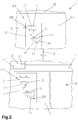
- FIGs. 2 to 4 A sequence for handling the laser plotter 2 for handling a machining process is now described schematically, in which a partial section of the computer 15, in particular the work area 25 displayed therein, and a partial section of the laser plotter 2, in particular the processing area 8, is now shown in a simplified and schematic manner so that the course of the procedure can be seen.
- a machining job 16 is first created by the user or an already created machining job 16 is loaded.
- the processing job 16 contains a graphic 17 or a graphic area and identification features 28 which are displayed or represented or created on the external component 14, in particular the computer 15, on the work area 25, as shown in FIG Fig. 2 is shown in the work area 25.
- the identification features 28 and the graphic 17 or the graphic area are then applied to the workpiece 7, it being possible for this to take place, for example, by printing out onto the workpiece 7.
- the application can be carried out independently of the computer 15 or the laser plotter 2 by other devices, in particular a printing machine, which, however, processes the same processing job 16.
- the workpiece 7 is arranged in the processing area 8 of the laser plotter 2 with an optical unit 30 for detecting the recognition features 28 (see FIG Fig. 2 Machining table 9), whereby aids corresponding to this, such as stop rails 34a or the like, can be used as means for positioning.
- the recording or detection of the workpiece 7, in particular the identification features 28, takes place in order to determine the position and orientation of the workpiece 7, in particular the applied graphics 17 or the graphics area, in the machining area 8, that is, an automatic Orientation of the Workpiece 7 is made.
- the machining process is carried out after successful recognition of the workpiece 7, in particular the graphic 17 or the graphic area, whereby for this purpose the graphic 17 is preferably cut out by the laser 5 or 6, as is known from the prior art.
- the position on the display element 15 and on the laser plotter 2 can be matched so that the correct data, in particular the positions for the laser beam, at the start of a machining process 10 can be determined and transmitted, so that the correspondingly stored functions can be loaded and generated for the corresponding positions, as is known from the prior art for such machining processes.
- corresponding recognition features 28 are present, which are recognized by the laser plotter 2, in particular by an optical unit 30.
- the optical unit 30 is included preferably formed from a camera that records a certain area of the processing table 9, whereby corresponding setting options, such as the contrast, the brightness, the image size, etc., can be made on the computer 15.
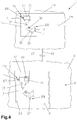
- the identification features 28 are preferably represented by register marks 31, as shown with circles, and / or graphic elements 32, as shown by a dashed circle in FIG Fig. 4 indicated, and / or workpiece element 33, such as a centering hole according to Fig.
- the identification feature 28 can be recorded by the optical unit 30 and at the same time it can be checked whether the settings for detection and evaluation work, ie that after the positioning the optical unit 30 records the identification feature 28 and a detection is carried out in order to determine whether a smooth Detection is possible.
- an adjustment path is stored between the laser pointer 27 and the optics unit 30, in particular a center of the optics unit 30, so that when the focusing unit 12, on which the optics unit 30 and the laser pointer 27 are arranged, are exchanged, correspondingly can be adapted to the new focusing unit 12.
- other required parameters can also be stored and changed.
- the laser plotter 2 moves the optics unit 30 to the predetermined position in such a way that the recognition feature 28 is within a definable search window 34, dashed in FIG Fig. 4 shown, the optical unit 30 is arranged.
- the identification feature 28 it is not absolutely necessary that the identification feature 28 has to be arranged in the center, but only at least partially but preferably completely this has to be present in the search window 34 so that it is recognized as the identification feature 28.
- the optics unit 30 and the laser 5, 6 or laser beam 10 coupled thereto are adjusted in such a way that the identification feature 28 is positioned in the center of the search window 34 or that at a recognition of the identification feature 28 within the search window 34, the position of the identification feature 28 relative to the center of the search window 34 or a starting position or defined point assigned to the search window 34 is calculated.
- a recognition feature 28 is not recognized by actuating an input means 21 on the laser plotter 2 or by activating a button on the display element 15, the unrecognized recognition feature 28 is skipped and the search process is continued with the next specified recognition feature 28 or manually the corresponding identification feature 28 is set on the laser plotter 2 by actuation via the input means 21, whereupon the machining process is continued.
- an error correction of the laser position on the laser plotter 2 takes place by actuating input means 21, the relative position of the laser position 26 to the graphics 17 or to the graphics area and / or the identification feature 28 is displayed on the display element 15, ie that, for example, the first identification feature 28 is not recognized during the first search process, so that the user can manually move to the first position, which is also displayed on the display element 15.
- the workpiece 7 is switched off after the machining process has ended removed from the machining area 8 and inserted a new workpiece 7.
- the new workpiece 7 is positioned at the same position as the previously processed workpiece 7, including means in the processing area 8 of the laser plotter 2, in particular the stop rails 34a, for positioning the workpiece 7, as in FIG Fig. 1 shown schematically, are arranged, whereupon the user closes a protective cover 35 for the processing area 8.
- the closing of the protective cover 35 is detected via a detection means 36, in particular a sensor contact, wherein, for safety reasons, the laser 5, 6 may not be operated without closing the protective cover 35.
- a detection means 36 in particular a sensor contact
- the laser 5, 6 may not be operated without closing the protective cover 35.
- a new processing process is started on the laser plotter 2 by activating an input means 21, in particular the confirmation means 23, so that the user is no longer, as is known from the prior art , must carry out the start of a new machining process on the computer 15, but can start directly on the laser plotter 2. It is of course possible that an independent input means 21 can be arranged and used for this purpose.
- a new machining process is started automatically by closing the protective cover 35 for the machining area 8 on the laser plotter 2.
- This can take place insofar as a laser power for processing the workpiece 7 is started or increased for the processing process after the first recognition feature 28, in particular a register mark 31 and / or a graphic element 32 and / or a workpiece element 33, has been recognized, ie after When the protective cover 35 is closed, the first or a defined number of identification features 28 is approached and recognized with reduced or switched off laser power, whereupon the laser power for processing, in particular for cutting, the workpiece 7 is increased.
- all recognition features 28 are recognized first with reduced or switched off laser power and only then is the laser power increased for the machining process in accordance with the set values shortly beforehand.
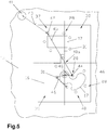
- FIG. 5 A schematic representation is now shown for the sequence for determining the sequence of the identifying features 28 to be interrogated or found one after the other, only a partial section of the display element 15 with the loaded processing job 16 being shown for this purpose.
- the graphic 17 or the graphic area is divided into several sectors 37, 38, 39, 40, in particular into four sectors 37, 38, 39, 40, for this purpose first a center point 40a or center or an optimal sector point of the graphic 17 or the graphics area is determined and specified.
- the division into sectors 37, 38, 39, 40 is indicated by dash-dotted lines in Fig. 5 shown schematically.
- the sequence of the identification features 28 to be queried is now established, with a first identification feature 28 to be queried being determined and defined in the first sector 37 as the first identification feature 28 to be queried, that is to say that preferably as the first sector 37, 38, 39, 40 that sector 37 is determined, which is the shortest adjustment path of the focus unit 12 from a starting point or a parking position 41, which is in the form of a circle in Fig. 5 is shown, and in this sector 37 now has that first identification feature 28, in particular a first register mark 42, with which the shortest travel path 43 from the parking position 41 is determined and established.
- a second identification feature 28 to be queried in particular a second register mark 44, is then determined and determined in a further sector 37, 38, 39, 40, in particular in the diagonal sector 40, the shortest adjustment path 45 from the previously determined first register mark 42 to the closest identification feature 28 is determined in the next sector 40.
- the determination of the closest identification feature 28 based on the Parking position 41 can take place.
- the further identification features 28 are then successively preferably always those identification features 28 with the shortest adjustment path 46 of the laser 5, 6 or the focus unit 12 determined and established, that is to say that the closest register mark 31 or the nearest identification feature 28 is always determined and thus the sequence for interrogating all identification features 28 is specified.
- the sequence can be saved for the corresponding machining job 16, so that such an analysis method is carried out only once when the machining job 16 is created.
- the laser plotter 2 first approaches the first identification feature 28, that is to say the first register mark 42 in this exemplary embodiment, and records this with the optics unit 30 and analyzes it accordingly.
- the image recorded by the optics unit 30 is saved to the corresponding register mark 42 in the processing job 16 so that the user can query this image during or after the processing process by simply moving or clicking on the register mark 42, which preferably opens a new window appears with the saved image.
- This process for storing the images of the register marks 31, 42, 44 that has been found is preferably carried out for each new work process or machining process, so that an analysis of the quality of the recorded register marks 31, 42, 44 can be carried out at later times and corresponding adjustments or adjustments can be made. Can carry out optimizations in the stored parameters for identification features 28. It is possible here for the images or images to be stored permanently in a memory or in the database 20 for the individual machining processes, which are provided with a sequential number, for example, or for the stored images or images to be overwritten each time a process is restarted . Additional information, such as the recognized position, deviations, recognition quality, etc., can also be stored.
- Fig. 6 and 7th shows a further training according to the invention to improve handling for the user.
- the workpiece 7 is processed as A4 format, so that the user can make a corresponding setting during commissioning, as in the Figs. 1 to 5 undertakes.
- the format of the workpiece 7 changes in the course of the work from, for example, A4 to A3
- the position of the graphic 17 on the workpiece 7 often changes, as in FIG Fig. 6 in the processing area 8 of the laser plotter 2 can be seen.
- the user has now inserted the workpiece 7 in A3 format, the position of the graphic 17 printed on the workpiece 7 having shifted.
- the focus unit 12, in particular with the search window 34 of the optics unit 30, moves to the first position that is to say the first register mark 42, where it was located in the previous machining process.
- This first register mark 42 is shown in dashed lines in order to identify the previous position.
- the focus unit 12, in particular the optics unit 30, cannot now find any register mark 42 due to the change in the graphics position due to the change in the workpiece format, whereupon the machining process is stopped.
- the original position of the workpiece 7 is still displayed in A4 format in the computer 15.
- the first identification feature 28, in particular the first register mark 42 is not recognized and the machining process is automatically stopped, as in FIG Fig. 6 evident.
- the user can now use the direction keys 22 on the laser plotter 2 to adjust the focusing unit 12 such that the search window 34 of the optics unit 30 or the laser pointer 27 is positioned over the first identification feature 28, in particular the first register mark 42 of the new position, and thus this can be recognized, whereupon the machining process is continued.
- the new positions of the recognition features 28 are stored so that after the machining process the new positions are displayed on the computer 15, as can be seen in FIG recognized position of the recognition features 28 and / or the associated graphics 17 or the graphics area is displayed in the work area 25 on the computer 15 at the corresponding position.
- the new location on the display element 15 can be shown flashing or with a changed color or inversely, or it is also possible that the old location or position is only shown with the identification features 28 and the new location or position with the identification features 28 and the Graph 17, as shown in Fig. 7 shown, or vice versa.
- a message 47 for correcting the new position or position of the graphic 17 or the graphic area is preferably displayed on the display element 15 and / or on the laser plotter 2, so that the new position for the next processing process when the input button "YES” is confirmed is corrected, whereas with "NO" the new displayed position of the graphic 17 or the identification features 28 is deleted and the original position is used for the next machining process.
- machining process or a method for engraving, marking, labeling and / or cutting workpieces with applied graphics, in particular a graphics area, with the laser plotter 2 is shown, the above
- the processes or processes described are also used for engraving or labeling.
- the machining job 16 is first created and / or loaded with a graphic 17 or a graphic area and identification features 28 on the display element 15, in particular the computer 15.
- the workpiece 7 must be produced for this purpose , ie that the identification features 28 and the graphics 17 or the graphics area on the workpiece 7 are applied to a base body or blank, in particular this is done by printing the processing job 16 on the workpiece 7.
- the workpiece 7 is then placed in the processing area 8 of the laser plotter 2 with the optical unit 30 for detecting the identification features 28 inserted.
- the workpiece 7, in particular the identification features 28, is recorded or detected in order to determine the position and orientation of the workpiece 7, in particular the applied graphics 17 or the graphics area, in the machining area 8, whereupon the complete machining process follows successful detection of the workpiece 7, in particular the graphic 17 or the graphic area, is carried out.
- one or more engraving areas 48 are defined, which are defined in the machining job 16 when the machining job 16 is created.
- the engraving areas 48 and / or inscription area are defined and stored as a function of the identification features 28, or that the engraving and / or inscription area 48 is defined and saved as a function of the graphic 17 or the graphic area, whereupon one or more of them are defined during the processing process after the detection Identification features 28, in particular of register marks 31, 42, 44 and / or graphic elements 32 or a part of the graphics and / or workpiece elements 33, a position of the engraving and / or inscription area 48 assigned to the identification features 28 is recognized.
- the necessary parameters can be set or assigned according to the design and the possible function of the laser plotter 2, so that, for example, with less powerful laser plotters 2, only a horizontal engraving with a small angular deviation of, for example, 1 to 3 ° can be set, whereas in the case of well-equipped laser plotters 2, an engraving angle of up to 45 ° or more is set. It is essential that an adaptation to the device or the laser plotter 2 can be made.
- these preset values are taken into account, so that the engraving process is stopped if a tolerance range of the specified parameters is exceeded, whereby the user is of course able to enable a release and thus a continuation of the engraving process through a manual input .
- the sequence for positioning and processing the workpiece 7 can be carried out as described above in such a way that after the workpiece 7 has been inserted in the processing area 8, the laser pointer 27 of the laser 5, 6 is positioned on any register mark 31, whereupon a on the display element 15 shown processing image of the graphic 17 or the graphic area with the associated identification features 28 on the display element 15 is shifted such that a laser position 26 displayed on the display element 15 corresponds to the identification feature 28 marked with the laser pointer 27.
- an analysis process is again carried out to determine the sequence of the identification features 28 to be queried one after the other, with the graphic 17 or the graphic area being divided into several sectors 37, 38, 39 , 40, especially in four sectors 37, 38, 39, 40 is divided, with the first register mark 42 to be interrogated being determined and established in the first sector 37, whereupon a second register mark 44 to be interrogated is determined and established in a further sector 37, 38, 39, 40, in particular in the diagonal sector 40, and then the further register marks 31 in succession, preferably always that register mark 31 with the shortest adjustment path 46 of the laser 4, 6, are determined and fixed.
- the workpiece 7 is removed from the machining area 8 and, if necessary, a new workpiece 7 is inserted, whereupon by activating an input means 21 on the laser plotter 2 or automatically by closing a protective cover 35 for the machining area 8 on the laser plotter 2 a new machining process is started so that the work processes for several identical engravings can be accelerated.
- a corresponding message 47 is generated in the event of a change in the position of the graphic 17, ie that after the processing process the actually recognized position of the recognition features 28 and / or the associated graphic 17 or the graphic area in the work area 25 on the work device 15 is displayed in the appropriate position.
- the identification features 28 can have different colors. This advantageously ensures that, for example, the accuracy for the machining process is controlled by interrogating all identification features 28 for the positioning for high accuracy, whereas with low accuracy but higher speed, a certain color is deactivated by the user can, whereby the number of identification features 28 is reduced.
- different degrees of accuracy can be defined.
- special identification features 28 are created and positioned, i.e. that, for example, different register marks 42, 44 (not shown) are used for the first and second and the further register marks 31 are again configured differently. This ensures, on the one hand, that the user can visually recognize which register mark 31, 42, 44 on the workpiece 7 is controlled first and second by the laser plotter 2. This also makes it easier for the laser pointer 27 to be executed on the first register mark 42 when positioning the laser pointer 27, for example, in order to enable improved positioning and recognition, for example by appropriately designing the shape and appearance of these register marks 42.
- identification features 28 in the exemplary embodiments for cutting out the graphic 17 and engraving the graphic 17 has the advantage that, on the one hand, the position of the workpiece 7 can be precisely determined and, on the other hand, any distortions or scaling are automatically recognized and taken into account, that is, that an adjustment takes place automatically in the event of corresponding distortions and / or scaling.
- positions approached with the laser pointer 27 it is possible for positions approached with the laser pointer 27 to be stored, for which purpose, for example, a corresponding mode can be selected or a corresponding input means 21 is provided.
- the user has the possibility of inserting the workpiece 7 into the processing area 8 as desired and then positioning it with the laser pointer 27 on an identification tag 28 and storing it through this position. After saving, the user can move the laser pointer 27 to a further identification feature 28 and again save this position. If the user then starts the machining process for engraving and / or cutting the workpiece 7, the laser plotter 2 and / or the computer 15 can carry out a corresponding calculation to identify the position of the workpiece 7 and process it.
- the user marks or stores several identification features 28 and / or shifts the graphic 17 in such a way that it corresponds to the first position, which is displayed on the computer 15, for example. It is also possible for all of the stored positions to be displayed so that the user can undertake a certain alignment himself and thus accelerate the position detection.
- a function is also possible in which the user first assigns a specific detection means 28 to a defined input means 21, in particular a "home button” on the computer 15, so that the user then places the workpiece 7 in the machining area 8, the focusing unit 12 to the defined identification feature 28 and by pressing the "home button” the graphic 17 is now automatically shifted to the laser position 26 on the display element 15.
- a processing job 16 can be loaded by means of external storage media 49, such as a USB stick, as shown schematically in FIG Fig. 1 is shown.
- external storage media 49 such as a USB stick
- the user only needs to connect the storage medium to the laser plotter 2, so that a corresponding recognition of one or more stored Processing jobs 16 take place, which are displayed on the display monitor 24 and can be selected.
- an external monitor is connected to the laser plotter 2
- the processing jobs 16 are also or only displayed on this.
- the storage medium 49 is connected to the processing job 16 on the laser plotter 2, so that the computer 15 accesses the storage medium 49, in particular the USB stick, via the laser plotter 2. It goes without saying that direct access to the storage medium 49 is possible when the storage medium 49 is connected directly to the display element 15 or the computer 15.
Landscapes
- Engineering & Computer Science (AREA)
- Mechanical Engineering (AREA)
- Life Sciences & Earth Sciences (AREA)
- Forests & Forestry (AREA)
- Physics & Mathematics (AREA)
- Optics & Photonics (AREA)
- Plasma & Fusion (AREA)
- Computer Vision & Pattern Recognition (AREA)
- General Engineering & Computer Science (AREA)
- Numerical Control (AREA)
- Laser Beam Processing (AREA)
Priority Applications (6)
| Application Number | Priority Date | Filing Date | Title |
|---|---|---|---|
| EP20212632.2A EP3943262B1 (de) | 2014-05-19 | 2015-05-04 | Verfahren zum gravieren, markieren, beschriften und/oder schneiden von werkstücken mit aufgebrachten graphik |
| EP20212630.6A EP3925742B1 (de) | 2014-05-19 | 2015-05-04 | Verfahren zum bearbeiten, insbesondere schneiden, einer auf einem werkstück aufgebrachten graphik, insbesondere eines graphikbereichs |
| EP20212627.2A EP3915742A1 (de) | 2014-05-19 | 2015-05-04 | Verfahren zum bearbeiten, insbesondere schneiden, einer auf einem werkstück aufgebrachten graphik, insbesondere eines graphikbereichs |
| EP20212628.0A EP3925741A1 (de) | 2014-05-19 | 2015-05-04 | Verfahren zum bearbeiten, insbesondere schneiden, einer auf einem werkstück aufgebrachten graphik |
| EP20212631.4A EP3939757B1 (de) | 2014-05-19 | 2015-05-04 | Verfahren zum gravieren, markieren, beschriften und/oder schneiden von werkstücken mit aufgebrachter graphik |
| PL15728380T PL3145685T3 (pl) | 2014-05-19 | 2015-05-04 | Sposób, urządzenie i ploter laserowy do obróbki przedmiotów |
Applications Claiming Priority (2)
| Application Number | Priority Date | Filing Date | Title |
|---|---|---|---|
| ATA50353/2014A AT515839B1 (de) | 2014-05-19 | 2014-05-19 | Verfahren und Einrichtung zum Bearbeiten von Werkstücken |
| PCT/AT2015/050109 WO2015176089A2 (de) | 2014-05-19 | 2015-05-04 | Verfahren, einrichtung und laserplotter zum bearbeiten von werkstücken |
Related Child Applications (15)
| Application Number | Title | Priority Date | Filing Date |
|---|---|---|---|
| EP20212628.0A Division EP3925741A1 (de) | 2014-05-19 | 2015-05-04 | Verfahren zum bearbeiten, insbesondere schneiden, einer auf einem werkstück aufgebrachten graphik |
| EP20212632.2A Division-Into EP3943262B1 (de) | 2014-05-19 | 2015-05-04 | Verfahren zum gravieren, markieren, beschriften und/oder schneiden von werkstücken mit aufgebrachten graphik |
| EP20212631.4A Division-Into EP3939757B1 (de) | 2014-05-19 | 2015-05-04 | Verfahren zum gravieren, markieren, beschriften und/oder schneiden von werkstücken mit aufgebrachter graphik |
| EP20212630.6A Division-Into EP3925742B1 (de) | 2014-05-19 | 2015-05-04 | Verfahren zum bearbeiten, insbesondere schneiden, einer auf einem werkstück aufgebrachten graphik, insbesondere eines graphikbereichs |
| EP20212627.2A Division-Into EP3915742A1 (de) | 2014-05-19 | 2015-05-04 | Verfahren zum bearbeiten, insbesondere schneiden, einer auf einem werkstück aufgebrachten graphik, insbesondere eines graphikbereichs |
| EP20212627.2A Division EP3915742A1 (de) | 2014-05-19 | 2015-05-04 | Verfahren zum bearbeiten, insbesondere schneiden, einer auf einem werkstück aufgebrachten graphik, insbesondere eines graphikbereichs |
| EP20212631.4A Division EP3939757B1 (de) | 2014-05-19 | 2015-05-04 | Verfahren zum gravieren, markieren, beschriften und/oder schneiden von werkstücken mit aufgebrachter graphik |
| EP20212630.6A Division EP3925742B1 (de) | 2014-05-19 | 2015-05-04 | Verfahren zum bearbeiten, insbesondere schneiden, einer auf einem werkstück aufgebrachten graphik, insbesondere eines graphikbereichs |
| EP20212632.2A Division EP3943262B1 (de) | 2014-05-19 | 2015-05-04 | Verfahren zum gravieren, markieren, beschriften und/oder schneiden von werkstücken mit aufgebrachten graphik |
| EP20212628.0A Division-Into EP3925741A1 (de) | 2014-05-19 | 2015-05-04 | Verfahren zum bearbeiten, insbesondere schneiden, einer auf einem werkstück aufgebrachten graphik |
| EP19218409.1 Division-Into | 2019-12-20 | ||
| EP19218408.3 Division-Into | 2019-12-20 | ||
| EP19218405.9 Division-Into | 2019-12-20 | ||
| EP19218399.4 Division-Into | 2019-12-20 | ||
| EP19218412.5 Division-Into | 2019-12-20 |
Publications (2)
| Publication Number | Publication Date |
|---|---|
| EP3145685A2 EP3145685A2 (de) | 2017-03-29 |
| EP3145685B1 true EP3145685B1 (de) | 2021-06-16 |
Family
ID=53385405
Family Applications (6)
| Application Number | Title | Priority Date | Filing Date |
|---|---|---|---|
| EP15728380.5A Active EP3145685B1 (de) | 2014-05-19 | 2015-05-04 | Verfahren, einrichtung und laserplotter zum bearbeiten von werkstücken |
| EP20212627.2A Withdrawn EP3915742A1 (de) | 2014-05-19 | 2015-05-04 | Verfahren zum bearbeiten, insbesondere schneiden, einer auf einem werkstück aufgebrachten graphik, insbesondere eines graphikbereichs |
| EP20212630.6A Active EP3925742B1 (de) | 2014-05-19 | 2015-05-04 | Verfahren zum bearbeiten, insbesondere schneiden, einer auf einem werkstück aufgebrachten graphik, insbesondere eines graphikbereichs |
| EP20212632.2A Active EP3943262B1 (de) | 2014-05-19 | 2015-05-04 | Verfahren zum gravieren, markieren, beschriften und/oder schneiden von werkstücken mit aufgebrachten graphik |
| EP20212631.4A Active EP3939757B1 (de) | 2014-05-19 | 2015-05-04 | Verfahren zum gravieren, markieren, beschriften und/oder schneiden von werkstücken mit aufgebrachter graphik |
| EP20212628.0A Withdrawn EP3925741A1 (de) | 2014-05-19 | 2015-05-04 | Verfahren zum bearbeiten, insbesondere schneiden, einer auf einem werkstück aufgebrachten graphik |
Family Applications After (5)
| Application Number | Title | Priority Date | Filing Date |
|---|---|---|---|
| EP20212627.2A Withdrawn EP3915742A1 (de) | 2014-05-19 | 2015-05-04 | Verfahren zum bearbeiten, insbesondere schneiden, einer auf einem werkstück aufgebrachten graphik, insbesondere eines graphikbereichs |
| EP20212630.6A Active EP3925742B1 (de) | 2014-05-19 | 2015-05-04 | Verfahren zum bearbeiten, insbesondere schneiden, einer auf einem werkstück aufgebrachten graphik, insbesondere eines graphikbereichs |
| EP20212632.2A Active EP3943262B1 (de) | 2014-05-19 | 2015-05-04 | Verfahren zum gravieren, markieren, beschriften und/oder schneiden von werkstücken mit aufgebrachten graphik |
| EP20212631.4A Active EP3939757B1 (de) | 2014-05-19 | 2015-05-04 | Verfahren zum gravieren, markieren, beschriften und/oder schneiden von werkstücken mit aufgebrachter graphik |
| EP20212628.0A Withdrawn EP3925741A1 (de) | 2014-05-19 | 2015-05-04 | Verfahren zum bearbeiten, insbesondere schneiden, einer auf einem werkstück aufgebrachten graphik |
Country Status (6)
| Country | Link |
|---|---|
| US (1) | US9815143B2 (pl) |
| EP (6) | EP3145685B1 (pl) |
| AT (1) | AT515839B1 (pl) |
| ES (1) | ES2879943T3 (pl) |
| PL (1) | PL3145685T3 (pl) |
| WO (1) | WO2015176089A2 (pl) |
Families Citing this family (14)
| Publication number | Priority date | Publication date | Assignee | Title |
|---|---|---|---|---|
| DE102013217783A1 (de) * | 2013-09-05 | 2015-03-05 | Sauer Gmbh Lasertec | Verfahren zur Bearbeitung eines Werkstücks mittels eines Laserstrahls, Laserwerkzeug, Lasermaschine, Maschinensteuerung |
| AT517185B1 (de) * | 2015-05-13 | 2017-06-15 | Trotec Laser Gmbh | Verfahren zum Gravieren, Markieren und/oder Beschriften eines Werkstückes () mit einem |
| AT517321A1 (de) | 2015-06-10 | 2016-12-15 | Trodat Gmbh | Stempel |
| AT517328B1 (de) | 2015-06-10 | 2024-06-15 | Trodat Gmbh | Stempel, ein Stempelkissen und eine Verschlusskappe |
| AT517322A1 (de) | 2015-06-10 | 2016-12-15 | Trodat Gmbh | Stempel und Abdruckeinheit, insbesondere als Ersatzteil für einen Stempel |
| AT518735B1 (de) | 2016-06-09 | 2024-09-15 | Trodat Gmbh | Antriebseinheit, Bandeinheit, Brücke, Mitnehmer und Stempel hierfür |
| AT519177B1 (de) * | 2016-10-06 | 2019-04-15 | Trotec Laser Gmbh | Verfahren zum Gravieren, Markieren und/oder Beschriften eines Werkstückes mit |
| EP4302949B1 (de) * | 2017-04-05 | 2026-02-18 | Zünd Systemtechnik Ag | Schneidemaschine mit überblickskamera |
| HRP20211716T1 (hr) | 2018-10-12 | 2022-02-18 | Dallan S.P.A. | Uređaj namijenjen rezanju komada iz lamelarnog materijala laserom ili plazmom |
| AT523710B1 (de) * | 2020-04-24 | 2021-11-15 | Trotec Laser Gmbh | Verfahren zum Betreiben und Steuern einer Laservorrichtung für das Gravieren, Markieren, Beschriften und/oder Schneiden eines vorzugsweiser flachen Werkstückes |
| AT523912B1 (de) * | 2020-04-24 | 2022-01-15 | Trotec Laser Gmbh | Verfahren zum Betreiben und Steuern einer Laservorrichtung für das Gravieren, Markieren, Beschriften und/oder Schneiden eines vorzugsweiser flachen Werkstückes |
| CN117226274A (zh) * | 2022-10-19 | 2023-12-15 | 杭州鸿世电器股份有限公司 | 一种柔性镭雕设备以及运行方法 |
| AT526893B1 (de) * | 2023-02-09 | 2025-02-15 | Trotec Laser Gmbh | Verfahren zum Erkennen eines wechselbaren Bearbeitungstisch bzw. Tischtype eines Laserplotters zum Schneiden, Gravieren, Markieren und/oder Beschriften eines Werkstückes, sowie einen Laserplotter zum Gravieren, Markieren und/oder Beschriften eines Werkstückes hierfür |
| CN117245228B (zh) * | 2023-11-20 | 2024-01-26 | 广东码清激光智能装备有限公司 | 工件识别及柔性加工装置、方法 |
Family Cites Families (18)
| Publication number | Priority date | Publication date | Assignee | Title |
|---|---|---|---|---|
| GB1365188A (en) * | 1971-09-23 | 1974-08-29 | Gerber Garment Technology Inc | Method for cutting sheet material and generating related conrol ler commands |
| GB1447490A (en) * | 1972-10-13 | 1976-08-25 | Solartron Electronic Group | Methods of and apparatus for testing weapon training systems |
| DE59505405D1 (de) * | 1994-04-23 | 1999-04-29 | Stahl Anton Dipl Betriebsw | Verfahren und Vorrichtung zur Bearbeitung von Schneidegut |
| EP0704283A1 (en) * | 1994-09-13 | 1996-04-03 | Summagraphics N.V. | Method and device for cutting a pattern in a sheet material |
| AT408632B (de) | 1998-01-29 | 2002-01-25 | Trodat Gmbh | Bearbeitungskopf für eine lasergravier- bzw. -schneidvorrichtung |
| CA2251243C (en) * | 1998-10-21 | 2006-12-19 | Robert Dworkowski | Distance tracking control system for single pass topographical mapping |
| US6772661B1 (en) | 1999-10-04 | 2004-08-10 | Mikkelsen Graphic Engineering | Method and apparatus for precision cutting and the like of graphics areas from sheets |
| US6619167B2 (en) | 2001-04-05 | 2003-09-16 | Steen Mikkelsen | Method and apparatus for precision cutting of graphics areas from sheets |
| US6672187B2 (en) | 2001-04-05 | 2004-01-06 | Mikkelsen Graphic Engineering, Inc. | Method and apparatus for rapid precision cutting of graphics areas from sheets |
| US7126082B2 (en) * | 2002-09-03 | 2006-10-24 | Xenetech, Inc. | Automated laser engraver |
| US7040204B2 (en) * | 2002-10-30 | 2006-05-09 | Mikkelsen Graphic Engineering | Method for preparing graphics on sheets |
| EP1577048A1 (de) | 2004-03-18 | 2005-09-21 | Trotec Produktions- und Vertriebs GMBH | Bearbeitungsvorrichtung mit zwei unterschiedlichen Bearbeitungswerkzeugen und Verfahren zum Steuern derselben |
| US8377246B2 (en) * | 2005-05-03 | 2013-02-19 | Paul Weedlun | Appliqué, having dual color effect by laser engraving |
| FR2903039A1 (fr) * | 2006-06-29 | 2008-01-04 | Didier Georges Dubesset | Dispositif d'apprentissage d'une forme a decouper autour de motifs imprimes sur un support d'impression plan, machine a decouper equipee d'un tel dispositif et procede pour sa mise en oeuvre. |
| US7859655B2 (en) * | 2007-09-28 | 2010-12-28 | The Boeing Company | Method involving a pointing instrument and a target object |
| US8680429B2 (en) * | 2009-11-10 | 2014-03-25 | Instrument Associates LLC | Laser beam scribing system |
| JP2011230178A (ja) * | 2010-04-30 | 2011-11-17 | Hoya Corp | 眼鏡レンズ用マーキング装置 |
| AT512092B1 (de) * | 2011-11-07 | 2014-03-15 | Trotec Produktions U Vertriebs Gmbh | Laserplotter und verfahren zum gravieren, markieren und/oder beschriften eines werkstückes |
-
2014
- 2014-05-19 AT ATA50353/2014A patent/AT515839B1/de not_active IP Right Cessation
-
2015
- 2015-05-04 WO PCT/AT2015/050109 patent/WO2015176089A2/de not_active Ceased
- 2015-05-04 EP EP15728380.5A patent/EP3145685B1/de active Active
- 2015-05-04 EP EP20212627.2A patent/EP3915742A1/de not_active Withdrawn
- 2015-05-04 EP EP20212630.6A patent/EP3925742B1/de active Active
- 2015-05-04 EP EP20212632.2A patent/EP3943262B1/de active Active
- 2015-05-04 EP EP20212631.4A patent/EP3939757B1/de active Active
- 2015-05-04 EP EP20212628.0A patent/EP3925741A1/de not_active Withdrawn
- 2015-05-04 ES ES15728380T patent/ES2879943T3/es active Active
- 2015-05-04 PL PL15728380T patent/PL3145685T3/pl unknown
- 2015-05-11 US US14/708,815 patent/US9815143B2/en active Active
Non-Patent Citations (1)
| Title |
|---|
| None * |
Also Published As
| Publication number | Publication date |
|---|---|
| PL3145685T3 (pl) | 2021-10-25 |
| EP3925742C0 (de) | 2024-10-16 |
| US20150360323A1 (en) | 2015-12-17 |
| EP3939757C0 (de) | 2024-10-30 |
| EP3943262A8 (de) | 2022-03-02 |
| WO2015176089A2 (de) | 2015-11-26 |
| EP3943262B1 (de) | 2024-10-30 |
| ES2879943T3 (es) | 2021-11-23 |
| EP3925742B1 (de) | 2024-10-16 |
| EP3939757A1 (de) | 2022-01-19 |
| WO2015176089A3 (de) | 2016-04-28 |
| EP3915742A1 (de) | 2021-12-01 |
| EP3925742A1 (de) | 2021-12-22 |
| EP3943262C0 (de) | 2024-10-30 |
| US9815143B2 (en) | 2017-11-14 |
| EP3943262A1 (de) | 2022-01-26 |
| AT515839B1 (de) | 2016-06-15 |
| AT515839A1 (de) | 2015-12-15 |
| EP3925741A1 (de) | 2021-12-22 |
| EP3939757B1 (de) | 2024-10-30 |
| EP3145685A2 (de) | 2017-03-29 |
Similar Documents
| Publication | Publication Date | Title |
|---|---|---|
| EP3145685B1 (de) | Verfahren, einrichtung und laserplotter zum bearbeiten von werkstücken | |
| DE102012106156B4 (de) | Verfahren zur Steuerung eines Werkzeuges | |
| EP3606709B1 (de) | Schneidemaschine mit überblickskamera | |
| EP3786737B1 (de) | Verfahren zur automatisierten einrichtung eines rohlings in einer bearbeitungsmaschine | |
| DE102014214058A1 (de) | Vorrichtung zur Herstellung eines dreidimensionalen Objekts und Verfahren zum Betreiben einer solchen Vorrichtung | |
| WO2018153937A1 (de) | Verfahren zum betreiben einer werkzeugsmaschine, insbesondere einer plattenbearbeitungsanlage zum bearbeiten plattenförmiger werkstücke, sowie werkzeugmaschine | |
| WO2019129654A1 (de) | Verfahren zum bearbeiten von werkstücken, sowie bearbeitungssystem | |
| EP4408604B1 (de) | Verfahren zum ermitteln einer position eines werkstücks in einem bearbeitungsraum eines laserplotter zum schneiden, gravieren, markieren und/oder beschriften des werkstückes, sowie verfahren zum kalibrieren und laserplotter hierfür | |
| DE102018101407B4 (de) | Werkzeugmaschine und Verfahren zur Vorbereitung einer Bearbeitung eines spanabtragenden Rotationswerkzeugs | |
| DE102011052586B4 (de) | Prägekopf mit Positionierungshilfe | |
| AT517799B1 (de) | Verfahren zum Bearbeiten von Werkstücken | |
| AT517797B1 (de) | Verfahren zum Bearbeiten von Werkstücken | |
| AT517800B1 (de) | Verfahren zum Bearbeiten von Werkstücken | |
| AT517572B1 (de) | Verfahren zum Bearbeiten von Werkstücken | |
| EP3001829B1 (de) | Stempelplattenrohling und verfahren zum erstellen einer textplatte für einen stempel | |
| AT517798B1 (de) | Verfahren zum Bearbeiten von Werkstücken | |
| AT526893B1 (de) | Verfahren zum Erkennen eines wechselbaren Bearbeitungstisch bzw. Tischtype eines Laserplotters zum Schneiden, Gravieren, Markieren und/oder Beschriften eines Werkstückes, sowie einen Laserplotter zum Gravieren, Markieren und/oder Beschriften eines Werkstückes hierfür | |
| AT517812B1 (de) | Verfahren zum Betreiben eines Bearbeitungssystems und ein Bearbeitungssystem, ein | |
| DE102017131373A1 (de) | Verfahren zum Bearbeiten von Werkstücken, sowie Bearbeitungssystem | |
| DE102024104146A1 (de) | Messsystem, Bearbeitungssystem sowie Markierverfahren zum Markieren eines Werkstücks | |
| CH718535B1 (de) | Verfahren und Werkzeugmaschinensystem zur Kollisionsprüfung eines Bearbeitungsprozesses, mit Ersatzwerkstück. | |
| DE102024120491A1 (de) | Verfahren zum Aufbringen einer Identifikationsnummer für ein Bauteil auf einem Rohbauprodukt und/oder auf einem Zwischenprodukt sowie Herstellungssystem | |
| AT525822A1 (de) | Verfahren zum Erkennen einer Linse und/oder Düse an einer Fokussiereinheit eines Laserplotters zum Schneiden, Gravieren, Markieren und/oder Beschriften eines Werkstückes, sowie Laserplotter zum Gravieren, Markieren und/oder Beschriften eines Werkstückes hierfür |
Legal Events
| Date | Code | Title | Description |
|---|---|---|---|
| STAA | Information on the status of an ep patent application or granted ep patent |
Free format text: STATUS: THE INTERNATIONAL PUBLICATION HAS BEEN MADE |
|
| PUAI | Public reference made under article 153(3) epc to a published international application that has entered the european phase |
Free format text: ORIGINAL CODE: 0009012 |
|
| STAA | Information on the status of an ep patent application or granted ep patent |
Free format text: STATUS: REQUEST FOR EXAMINATION WAS MADE |
|
| 17P | Request for examination filed |
Effective date: 20161219 |
|
| AK | Designated contracting states |
Kind code of ref document: A2 Designated state(s): AL AT BE BG CH CY CZ DE DK EE ES FI FR GB GR HR HU IE IS IT LI LT LU LV MC MK MT NL NO PL PT RO RS SE SI SK SM TR |
|
| AX | Request for extension of the european patent |
Extension state: BA ME |
|
| DAV | Request for validation of the european patent (deleted) | ||
| DAX | Request for extension of the european patent (deleted) | ||
| REG | Reference to a national code |
Ref country code: DE Ref legal event code: R079 Ref document number: 502015014828 Country of ref document: DE Free format text: PREVIOUS MAIN CLASS: B26D0005300000 Ipc: B26F0001380000 |
|
| RIC1 | Information provided on ipc code assigned before grant |
Ipc: B26D 5/00 20060101ALI20190628BHEP Ipc: B23K 26/38 20140101ALI20190628BHEP Ipc: B26F 1/38 20060101AFI20190628BHEP Ipc: B23K 26/02 20140101ALI20190628BHEP |
|
| STAA | Information on the status of an ep patent application or granted ep patent |
Free format text: STATUS: EXAMINATION IS IN PROGRESS |
|
| 17Q | First examination report despatched |
Effective date: 20190828 |
|
| RAP1 | Party data changed (applicant data changed or rights of an application transferred) |
Owner name: TROTEC LASER GMBH |
|
| GRAP | Despatch of communication of intention to grant a patent |
Free format text: ORIGINAL CODE: EPIDOSNIGR1 |
|
| STAA | Information on the status of an ep patent application or granted ep patent |
Free format text: STATUS: GRANT OF PATENT IS INTENDED |
|
| INTG | Intention to grant announced |
Effective date: 20210114 |
|
| GRAS | Grant fee paid |
Free format text: ORIGINAL CODE: EPIDOSNIGR3 |
|
| GRAA | (expected) grant |
Free format text: ORIGINAL CODE: 0009210 |
|
| STAA | Information on the status of an ep patent application or granted ep patent |
Free format text: STATUS: THE PATENT HAS BEEN GRANTED |
|
| RAP3 | Party data changed (applicant data changed or rights of an application transferred) |
Owner name: TROTEC LASER GMBH |
|
| AK | Designated contracting states |
Kind code of ref document: B1 Designated state(s): AL AT BE BG CH CY CZ DE DK EE ES FI FR GB GR HR HU IE IS IT LI LT LU LV MC MK MT NL NO PL PT RO RS SE SI SK SM TR |
|
| REG | Reference to a national code |
Ref country code: GB Ref legal event code: FG4D Free format text: NOT ENGLISH |
|
| REG | Reference to a national code |
Ref country code: CH Ref legal event code: EP |
|
| REG | Reference to a national code |
Ref country code: DE Ref legal event code: R096 Ref document number: 502015014828 Country of ref document: DE |
|
| REG | Reference to a national code |
Ref country code: AT Ref legal event code: REF Ref document number: 1401937 Country of ref document: AT Kind code of ref document: T Effective date: 20210715 |
|
| REG | Reference to a national code |
Ref country code: IE Ref legal event code: FG4D Free format text: LANGUAGE OF EP DOCUMENT: GERMAN Ref country code: NL Ref legal event code: FP |
|
| REG | Reference to a national code |
Ref country code: LT Ref legal event code: MG9D |
|
| PG25 | Lapsed in a contracting state [announced via postgrant information from national office to epo] |
Ref country code: LT Free format text: LAPSE BECAUSE OF FAILURE TO SUBMIT A TRANSLATION OF THE DESCRIPTION OR TO PAY THE FEE WITHIN THE PRESCRIBED TIME-LIMIT Effective date: 20210616 Ref country code: FI Free format text: LAPSE BECAUSE OF FAILURE TO SUBMIT A TRANSLATION OF THE DESCRIPTION OR TO PAY THE FEE WITHIN THE PRESCRIBED TIME-LIMIT Effective date: 20210616 Ref country code: BG Free format text: LAPSE BECAUSE OF FAILURE TO SUBMIT A TRANSLATION OF THE DESCRIPTION OR TO PAY THE FEE WITHIN THE PRESCRIBED TIME-LIMIT Effective date: 20210916 Ref country code: HR Free format text: LAPSE BECAUSE OF FAILURE TO SUBMIT A TRANSLATION OF THE DESCRIPTION OR TO PAY THE FEE WITHIN THE PRESCRIBED TIME-LIMIT Effective date: 20210616 |
|
| REG | Reference to a national code |
Ref country code: ES Ref legal event code: FG2A Ref document number: 2879943 Country of ref document: ES Kind code of ref document: T3 Effective date: 20211123 |
|
| PG25 | Lapsed in a contracting state [announced via postgrant information from national office to epo] |
Ref country code: LV Free format text: LAPSE BECAUSE OF FAILURE TO SUBMIT A TRANSLATION OF THE DESCRIPTION OR TO PAY THE FEE WITHIN THE PRESCRIBED TIME-LIMIT Effective date: 20210616 Ref country code: GR Free format text: LAPSE BECAUSE OF FAILURE TO SUBMIT A TRANSLATION OF THE DESCRIPTION OR TO PAY THE FEE WITHIN THE PRESCRIBED TIME-LIMIT Effective date: 20210917 Ref country code: NO Free format text: LAPSE BECAUSE OF FAILURE TO SUBMIT A TRANSLATION OF THE DESCRIPTION OR TO PAY THE FEE WITHIN THE PRESCRIBED TIME-LIMIT Effective date: 20210916 Ref country code: RS Free format text: LAPSE BECAUSE OF FAILURE TO SUBMIT A TRANSLATION OF THE DESCRIPTION OR TO PAY THE FEE WITHIN THE PRESCRIBED TIME-LIMIT Effective date: 20210616 Ref country code: SE Free format text: LAPSE BECAUSE OF FAILURE TO SUBMIT A TRANSLATION OF THE DESCRIPTION OR TO PAY THE FEE WITHIN THE PRESCRIBED TIME-LIMIT Effective date: 20210616 |
|
| PG25 | Lapsed in a contracting state [announced via postgrant information from national office to epo] |
Ref country code: CZ Free format text: LAPSE BECAUSE OF FAILURE TO SUBMIT A TRANSLATION OF THE DESCRIPTION OR TO PAY THE FEE WITHIN THE PRESCRIBED TIME-LIMIT Effective date: 20210616 Ref country code: EE Free format text: LAPSE BECAUSE OF FAILURE TO SUBMIT A TRANSLATION OF THE DESCRIPTION OR TO PAY THE FEE WITHIN THE PRESCRIBED TIME-LIMIT Effective date: 20210616 Ref country code: SM Free format text: LAPSE BECAUSE OF FAILURE TO SUBMIT A TRANSLATION OF THE DESCRIPTION OR TO PAY THE FEE WITHIN THE PRESCRIBED TIME-LIMIT Effective date: 20210616 Ref country code: SK Free format text: LAPSE BECAUSE OF FAILURE TO SUBMIT A TRANSLATION OF THE DESCRIPTION OR TO PAY THE FEE WITHIN THE PRESCRIBED TIME-LIMIT Effective date: 20210616 Ref country code: PT Free format text: LAPSE BECAUSE OF FAILURE TO SUBMIT A TRANSLATION OF THE DESCRIPTION OR TO PAY THE FEE WITHIN THE PRESCRIBED TIME-LIMIT Effective date: 20211018 Ref country code: RO Free format text: LAPSE BECAUSE OF FAILURE TO SUBMIT A TRANSLATION OF THE DESCRIPTION OR TO PAY THE FEE WITHIN THE PRESCRIBED TIME-LIMIT Effective date: 20210616 |
|
| REG | Reference to a national code |
Ref country code: DE Ref legal event code: R097 Ref document number: 502015014828 Country of ref document: DE |
|
| PLBE | No opposition filed within time limit |
Free format text: ORIGINAL CODE: 0009261 |
|
| STAA | Information on the status of an ep patent application or granted ep patent |
Free format text: STATUS: NO OPPOSITION FILED WITHIN TIME LIMIT |
|
| PG25 | Lapsed in a contracting state [announced via postgrant information from national office to epo] |
Ref country code: DK Free format text: LAPSE BECAUSE OF FAILURE TO SUBMIT A TRANSLATION OF THE DESCRIPTION OR TO PAY THE FEE WITHIN THE PRESCRIBED TIME-LIMIT Effective date: 20210616 |
|
| PGFP | Annual fee paid to national office [announced via postgrant information from national office to epo] |
Ref country code: GB Payment date: 20220331 Year of fee payment: 8 |
|
| 26N | No opposition filed |
Effective date: 20220317 |
|
| PG25 | Lapsed in a contracting state [announced via postgrant information from national office to epo] |
Ref country code: AL Free format text: LAPSE BECAUSE OF FAILURE TO SUBMIT A TRANSLATION OF THE DESCRIPTION OR TO PAY THE FEE WITHIN THE PRESCRIBED TIME-LIMIT Effective date: 20210616 |
|
| PGFP | Annual fee paid to national office [announced via postgrant information from national office to epo] |
Ref country code: FR Payment date: 20220331 Year of fee payment: 8 |
|
| PGFP | Annual fee paid to national office [announced via postgrant information from national office to epo] |
Ref country code: NL Payment date: 20220401 Year of fee payment: 8 |
|
| PGFP | Annual fee paid to national office [announced via postgrant information from national office to epo] |
Ref country code: IT Payment date: 20220401 Year of fee payment: 8 Ref country code: ES Payment date: 20220608 Year of fee payment: 8 Ref country code: DE Payment date: 20220401 Year of fee payment: 8 |
|
| PGFP | Annual fee paid to national office [announced via postgrant information from national office to epo] |
Ref country code: TR Payment date: 20220429 Year of fee payment: 8 Ref country code: PL Payment date: 20220420 Year of fee payment: 8 Ref country code: CH Payment date: 20220404 Year of fee payment: 8 |
|
| REG | Reference to a national code |
Ref country code: BE Ref legal event code: MM Effective date: 20220531 |
|
| PG25 | Lapsed in a contracting state [announced via postgrant information from national office to epo] |
Ref country code: MC Free format text: LAPSE BECAUSE OF FAILURE TO SUBMIT A TRANSLATION OF THE DESCRIPTION OR TO PAY THE FEE WITHIN THE PRESCRIBED TIME-LIMIT Effective date: 20210616 Ref country code: LU Free format text: LAPSE BECAUSE OF NON-PAYMENT OF DUE FEES Effective date: 20220504 |
|
| PG25 | Lapsed in a contracting state [announced via postgrant information from national office to epo] |
Ref country code: IE Free format text: LAPSE BECAUSE OF NON-PAYMENT OF DUE FEES Effective date: 20220504 |
|
| PG25 | Lapsed in a contracting state [announced via postgrant information from national office to epo] |
Ref country code: BE Free format text: LAPSE BECAUSE OF NON-PAYMENT OF DUE FEES Effective date: 20220531 |
|
| REG | Reference to a national code |
Ref country code: AT Ref legal event code: MM01 Ref document number: 1401937 Country of ref document: AT Kind code of ref document: T Effective date: 20220504 |
|
| PG25 | Lapsed in a contracting state [announced via postgrant information from national office to epo] |
Ref country code: AT Free format text: LAPSE BECAUSE OF NON-PAYMENT OF DUE FEES Effective date: 20220504 |
|
| REG | Reference to a national code |
Ref country code: DE Ref legal event code: R119 Ref document number: 502015014828 Country of ref document: DE |
|
| REG | Reference to a national code |
Ref country code: CH Ref legal event code: PL |
|
| REG | Reference to a national code |
Ref country code: NL Ref legal event code: MM Effective date: 20230601 |
|
| GBPC | Gb: european patent ceased through non-payment of renewal fee |
Effective date: 20230504 |
|
| PG25 | Lapsed in a contracting state [announced via postgrant information from national office to epo] |
Ref country code: LI Free format text: LAPSE BECAUSE OF NON-PAYMENT OF DUE FEES Effective date: 20230531 Ref country code: CH Free format text: LAPSE BECAUSE OF NON-PAYMENT OF DUE FEES Effective date: 20230531 |
|
| PG25 | Lapsed in a contracting state [announced via postgrant information from national office to epo] |
Ref country code: NL Free format text: LAPSE BECAUSE OF NON-PAYMENT OF DUE FEES Effective date: 20230601 |
|
| PG25 | Lapsed in a contracting state [announced via postgrant information from national office to epo] |
Ref country code: HU Free format text: LAPSE BECAUSE OF FAILURE TO SUBMIT A TRANSLATION OF THE DESCRIPTION OR TO PAY THE FEE WITHIN THE PRESCRIBED TIME-LIMIT; INVALID AB INITIO Effective date: 20150504 |
|
| PG25 | Lapsed in a contracting state [announced via postgrant information from national office to epo] |
Ref country code: MK Free format text: LAPSE BECAUSE OF FAILURE TO SUBMIT A TRANSLATION OF THE DESCRIPTION OR TO PAY THE FEE WITHIN THE PRESCRIBED TIME-LIMIT Effective date: 20210616 Ref country code: IT Free format text: LAPSE BECAUSE OF NON-PAYMENT OF DUE FEES Effective date: 20230504 Ref country code: DE Free format text: LAPSE BECAUSE OF NON-PAYMENT OF DUE FEES Effective date: 20231201 Ref country code: CY Free format text: LAPSE BECAUSE OF FAILURE TO SUBMIT A TRANSLATION OF THE DESCRIPTION OR TO PAY THE FEE WITHIN THE PRESCRIBED TIME-LIMIT Effective date: 20210616 Ref country code: GB Free format text: LAPSE BECAUSE OF NON-PAYMENT OF DUE FEES Effective date: 20230504 |
|
| PG25 | Lapsed in a contracting state [announced via postgrant information from national office to epo] |
Ref country code: FR Free format text: LAPSE BECAUSE OF NON-PAYMENT OF DUE FEES Effective date: 20230531 |
|
| REG | Reference to a national code |
Ref country code: ES Ref legal event code: FD2A Effective date: 20240626 |
|
| PG25 | Lapsed in a contracting state [announced via postgrant information from national office to epo] |
Ref country code: ES Free format text: LAPSE BECAUSE OF NON-PAYMENT OF DUE FEES Effective date: 20230505 |
|
| PG25 | Lapsed in a contracting state [announced via postgrant information from national office to epo] |
Ref country code: ES Free format text: LAPSE BECAUSE OF NON-PAYMENT OF DUE FEES Effective date: 20230505 |
|
| PG25 | Lapsed in a contracting state [announced via postgrant information from national office to epo] |
Ref country code: MT Free format text: LAPSE BECAUSE OF FAILURE TO SUBMIT A TRANSLATION OF THE DESCRIPTION OR TO PAY THE FEE WITHIN THE PRESCRIBED TIME-LIMIT Effective date: 20210616 |
|
| PG25 | Lapsed in a contracting state [announced via postgrant information from national office to epo] |
Ref country code: PL Free format text: LAPSE BECAUSE OF NON-PAYMENT OF DUE FEES Effective date: 20230504 |
|
| PG25 | Lapsed in a contracting state [announced via postgrant information from national office to epo] |
Ref country code: PL Free format text: LAPSE BECAUSE OF NON-PAYMENT OF DUE FEES Effective date: 20230504 |