EP3145464B1 - Method for producing at least one suction insert, and a suction insert - Google Patents
Method for producing at least one suction insert, and a suction insert Download PDFInfo
- Publication number
- EP3145464B1 EP3145464B1 EP15723502.9A EP15723502A EP3145464B1 EP 3145464 B1 EP3145464 B1 EP 3145464B1 EP 15723502 A EP15723502 A EP 15723502A EP 3145464 B1 EP3145464 B1 EP 3145464B1
- Authority
- EP
- European Patent Office
- Prior art keywords
- material web
- absorbent
- laminating
- folded
- web
- Prior art date
- Legal status (The legal status is an assumption and is not a legal conclusion. Google has not performed a legal analysis and makes no representation as to the accuracy of the status listed.)
- Active
Links
Images


Classifications
-
- A—HUMAN NECESSITIES
- A61—MEDICAL OR VETERINARY SCIENCE; HYGIENE
- A61F—FILTERS IMPLANTABLE INTO BLOOD VESSELS; PROSTHESES; DEVICES PROVIDING PATENCY TO, OR PREVENTING COLLAPSING OF, TUBULAR STRUCTURES OF THE BODY, e.g. STENTS; ORTHOPAEDIC, NURSING OR CONTRACEPTIVE DEVICES; FOMENTATION; TREATMENT OR PROTECTION OF EYES OR EARS; BANDAGES, DRESSINGS OR ABSORBENT PADS; FIRST-AID KITS
- A61F13/00—Bandages or dressings; Absorbent pads
- A61F13/15—Absorbent pads, e.g. sanitary towels, swabs or tampons for external or internal application to the body; Supporting or fastening means therefor; Tampon applicators
- A61F13/53—Absorbent pads, e.g. sanitary towels, swabs or tampons for external or internal application to the body; Supporting or fastening means therefor; Tampon applicators characterised by the absorbing medium
- A61F13/534—Absorbent pads, e.g. sanitary towels, swabs or tampons for external or internal application to the body; Supporting or fastening means therefor; Tampon applicators characterised by the absorbing medium having an inhomogeneous composition through the thickness of the pad
- A61F13/537—Absorbent pads, e.g. sanitary towels, swabs or tampons for external or internal application to the body; Supporting or fastening means therefor; Tampon applicators characterised by the absorbing medium having an inhomogeneous composition through the thickness of the pad characterised by a layer facilitating or inhibiting flow in one direction or plane, e.g. a wicking layer
-
- A—HUMAN NECESSITIES
- A61—MEDICAL OR VETERINARY SCIENCE; HYGIENE
- A61F—FILTERS IMPLANTABLE INTO BLOOD VESSELS; PROSTHESES; DEVICES PROVIDING PATENCY TO, OR PREVENTING COLLAPSING OF, TUBULAR STRUCTURES OF THE BODY, e.g. STENTS; ORTHOPAEDIC, NURSING OR CONTRACEPTIVE DEVICES; FOMENTATION; TREATMENT OR PROTECTION OF EYES OR EARS; BANDAGES, DRESSINGS OR ABSORBENT PADS; FIRST-AID KITS
- A61F13/00—Bandages or dressings; Absorbent pads
- A61F13/15—Absorbent pads, e.g. sanitary towels, swabs or tampons for external or internal application to the body; Supporting or fastening means therefor; Tampon applicators
- A61F13/15577—Apparatus or processes for manufacturing
- A61F13/15617—Making absorbent pads from fibres or pulverulent material with or without treatment of the fibres
- A61F13/1565—Making absorbent pads from fibres or pulverulent material with or without treatment of the fibres by depositing continuous layers of fibrous material between webs, e.g. wrapping layers of fibrous material
-
- A—HUMAN NECESSITIES
- A61—MEDICAL OR VETERINARY SCIENCE; HYGIENE
- A61F—FILTERS IMPLANTABLE INTO BLOOD VESSELS; PROSTHESES; DEVICES PROVIDING PATENCY TO, OR PREVENTING COLLAPSING OF, TUBULAR STRUCTURES OF THE BODY, e.g. STENTS; ORTHOPAEDIC, NURSING OR CONTRACEPTIVE DEVICES; FOMENTATION; TREATMENT OR PROTECTION OF EYES OR EARS; BANDAGES, DRESSINGS OR ABSORBENT PADS; FIRST-AID KITS
- A61F13/00—Bandages or dressings; Absorbent pads
- A61F13/15—Absorbent pads, e.g. sanitary towels, swabs or tampons for external or internal application to the body; Supporting or fastening means therefor; Tampon applicators
- A61F13/15577—Apparatus or processes for manufacturing
- A61F13/15666—Wrapping formed fibrous webs or pads, e.g. the pads being formed by uniting pad pieces cut from fibrous webs
-
- A—HUMAN NECESSITIES
- A61—MEDICAL OR VETERINARY SCIENCE; HYGIENE
- A61F—FILTERS IMPLANTABLE INTO BLOOD VESSELS; PROSTHESES; DEVICES PROVIDING PATENCY TO, OR PREVENTING COLLAPSING OF, TUBULAR STRUCTURES OF THE BODY, e.g. STENTS; ORTHOPAEDIC, NURSING OR CONTRACEPTIVE DEVICES; FOMENTATION; TREATMENT OR PROTECTION OF EYES OR EARS; BANDAGES, DRESSINGS OR ABSORBENT PADS; FIRST-AID KITS
- A61F13/00—Bandages or dressings; Absorbent pads
- A61F13/15—Absorbent pads, e.g. sanitary towels, swabs or tampons for external or internal application to the body; Supporting or fastening means therefor; Tampon applicators
- A61F13/53—Absorbent pads, e.g. sanitary towels, swabs or tampons for external or internal application to the body; Supporting or fastening means therefor; Tampon applicators characterised by the absorbing medium
- A61F13/534—Absorbent pads, e.g. sanitary towels, swabs or tampons for external or internal application to the body; Supporting or fastening means therefor; Tampon applicators characterised by the absorbing medium having an inhomogeneous composition through the thickness of the pad
- A61F13/53409—Absorbent pads, e.g. sanitary towels, swabs or tampons for external or internal application to the body; Supporting or fastening means therefor; Tampon applicators characterised by the absorbing medium having an inhomogeneous composition through the thickness of the pad having a folded core
- A61F13/53418—Absorbent pads, e.g. sanitary towels, swabs or tampons for external or internal application to the body; Supporting or fastening means therefor; Tampon applicators characterised by the absorbing medium having an inhomogeneous composition through the thickness of the pad having a folded core having a C-folded cross-section
-
- A—HUMAN NECESSITIES
- A61—MEDICAL OR VETERINARY SCIENCE; HYGIENE
- A61F—FILTERS IMPLANTABLE INTO BLOOD VESSELS; PROSTHESES; DEVICES PROVIDING PATENCY TO, OR PREVENTING COLLAPSING OF, TUBULAR STRUCTURES OF THE BODY, e.g. STENTS; ORTHOPAEDIC, NURSING OR CONTRACEPTIVE DEVICES; FOMENTATION; TREATMENT OR PROTECTION OF EYES OR EARS; BANDAGES, DRESSINGS OR ABSORBENT PADS; FIRST-AID KITS
- A61F13/00—Bandages or dressings; Absorbent pads
- A61F13/15—Absorbent pads, e.g. sanitary towels, swabs or tampons for external or internal application to the body; Supporting or fastening means therefor; Tampon applicators
- A61F13/53—Absorbent pads, e.g. sanitary towels, swabs or tampons for external or internal application to the body; Supporting or fastening means therefor; Tampon applicators characterised by the absorbing medium
- A61F13/534—Absorbent pads, e.g. sanitary towels, swabs or tampons for external or internal application to the body; Supporting or fastening means therefor; Tampon applicators characterised by the absorbing medium having an inhomogeneous composition through the thickness of the pad
- A61F13/53409—Absorbent pads, e.g. sanitary towels, swabs or tampons for external or internal application to the body; Supporting or fastening means therefor; Tampon applicators characterised by the absorbing medium having an inhomogeneous composition through the thickness of the pad having a folded core
- A61F13/53427—Absorbent pads, e.g. sanitary towels, swabs or tampons for external or internal application to the body; Supporting or fastening means therefor; Tampon applicators characterised by the absorbing medium having an inhomogeneous composition through the thickness of the pad having a folded core having an e-folded cross-section
Definitions
- the invention relates to a method for producing at least one absorbent pad and a suction pad.
- Suction pads especially for the food industry for the absorption of superfluous liquids in a product package are known from the prior art.
- this describes DE 10 2004 043 289 A1 a method for the production of liquid-absorbent absorbent pads as well as liquid absorbent absorbent pads, wherein first a first web is fed to a loading station, are formed in the spaced exactly pillows of pulp and optionally superabsorbent on the web. Subsequently, a second material web is fed parallel to the first material web and glued together.
- CN 201980578 U describes a water-absorbent pad comprising an absorbent material of a blend of wood fibers and superabsorbent or absorbent paper having superabsorbent and externally wrapped in toilet paper.
- US 2008/0167634 A1 describes an absorbent article, especially a diaper, having a absorbent core wrapped with a fibrous material.
- the superabsorbent particles are either scattered between two layers of the fibrous web or applied to a web of material and held therein by means of an e-fold.
- the object of the invention is to provide an improved process for the preparation of a absorbent insert available. Another object of the invention is to provide an improved absorbent pad.
- the edge region is a region of the unfolded material web which borders on the edges perpendicular to the machine direction. If, for example, an edge perpendicular to the machine direction is folded substantially onto the opposite edge -V-fold - and in a subsequent step both edge regions are folded back towards the fold or fold, a four-layer absorbent core is produced. This two-fold V-fold is called in the following double-V-fold.
- production steps are indicated in chronological order within the scope of the invention, this means production steps of a section of the raw material used in the machine direction.
- a material web is to be understood as meaning a web-shaped surface product of cellulose, in particular cellulose wadding or tissue, of a nonwoven, of a nonwoven and / or of a woven or knitted material.
- the material includes in one embodiment, at least one material selected from a group comprising a pulp and / or a thermoplastic, such as a polyolefin.
- a non-inventive folding is such that either the edge region is folded over the superabsorber, so that the second edge region is not covered by the first edge region and then the second edge region is folded over the first edge region.
- This convolution is called e-folding below.
- a preferred possibility of the folding is such that the first edge region is folded over the superabsorber and the second edge region, so that the two material web edges lie substantially on and / or one above the other and subsequently the two superimposed edge regions are folded back or folded again, so that the absorbent insert is designed in four layers.
- the folding point is struck on the superimposed edge regions.
- the superabsorbent is applied to the material web in such a way and in particular fixed, that it is arranged substantially in the lower layer of the fabricated absorbent insert or of the absorbent core.
- the superabsorber is applied to the material web and the material web is folded in such a way that the portion of the material web on which the superabsorber is applied is moved exclusively in the machine direction. Preferably, this portion is not folded up during the folding process, so that the superabsorbent is not moved relative to the material web substantially by the folding.
- the material web width of the unfolded material web is preferably adjusted to the product width of the finished product.
- the total width of the unfolded material web is a multiple of the absorbent insert width.
- the web width of the cellulose wadding web is then about four times, ie about 36 cm.
- the material web is folded twice according to the invention, that is to say a double-V folding is carried out.
- both edge regions of the material web remain free of superabsorbers. This has the advantage that in the case of the four-ply folding or the double-V folding, in which one of the edge regions is not enclosed by the fold from the rest of the material web, no superabsorbent is released to the environment. That is, trickling out of the superabsorber perpendicular to the machine direction is avoided even in the finished product. It is also achieved that, when using the superabsorbent, in particular by the swelling of the superabsorber, the superabsorber is held in the absorbent core.
- the superabsorber is provided in Schau of the inventive double V-fold only to about a quarter of the web width of the web.
- the superabsorber is applied only on the region of the material web which forms the lower layer of the folded material web.
- the superabsorber is guided or conveyed by an application system into a channel formed during the folding of the material web, more preferably a tunnel.
- the channel formed at least partially by the material web is preferably open on one side.
- This channel is formed, for example, by a folding mechanism, wherein the fold is not completely executed at the point where the channel is formed or at which the superabsorber is applied.
- the folding process is terminated immediately after the attachment of the superabsorber and the superabsorber is integrated in the folded material web and in particular prefixed.
- a tunnel is formed from the material web. In particular, a convolution partially executed to form the tunnel.
- Superabsorber is introduced into this tunnel, preferably before the folding is complete.
- the superabsorbent is preferably introduced in the machine direction from behind into the tunnel.
- the application system is designed as a lance, sword, air flow or roller conveyor.
- the superabsorber is fixed on the material web in such a way that it is preferably arranged on and / or in the lower layer of the manufactured absorbent core of the absorbent insert even after folding. This advantageously ensures that the liquid to be absorbed immediately reaches the superabsorber and this can absorb the liquid immediately. Further preferably, the remaining layers of the material web are arranged above the superabsorber and are designed such that they act by the capillary action for a uniform distribution of the liquid in the absorbent core, in particular to be able to exploit the full effect of the superabsorbent can.
- a suction core is to be understood as the folded material web, which in particular also includes the superabsorber.
- the absorbent insert comprises the absorbent core and, in addition, further components, such as a lamination.
- the superabsorber is comminuted, in particular comminuted, during calendering of the absorbent core.
- the calendering or calendering of the absorbent core has the advantage that a compact unit of material web and superabsorber is achieved, wherein the comminuted superabsorber in anchored the material web.
- Another advantage of the comminution of the superabsorber is that it has a larger surface area for receiving liquid than the uncrushed superabsorber.
- the superabsorber can be applied relatively coarsely to the material web, which allows handling and in particular a higher machine speed; Nevertheless, the advantages of a relatively fine-grained superabsorbent in the absorbent core or in the absorbent insert can be used. It is also advantageous in one embodiment that the superabsorber is anchored by calendering in the material web. Preferably, there is a mechanical attachment between the superabsorbent and the material of the web.
- the material web be moistened, in particular before the superabsorber is applied to the material web. This has the advantage that the superabsorbent is activated and anchored in the fibers of the material web. In a further embodiment, it is provided that the material web remains dry in the production process, that is, a moisture content according to DIN 54540 Part 4, June 1989, from about 0% to about 10%, preferably about 3% to about 8%.
- the laminating material is at least one material selected from a group comprising a film, a woven fabric and / or a knitted fabric.
- the laminating material comprises polyethylene, polypropylene and / or paper.
- the laminating material is produced from a woven or knitted fabric.
- the laminating material is designed such that it acts hydrophilic.
- the laminating material comprises a film with a valve effect and / or a hydrophilically configured nonwoven material, so that the liquid to be absorbed reaches the absorbent core as fast as possible and is bound by the superabsorber embedded in it.
- a valve action of the laminating material is achieved in particular by openings which are produced, for example, by means of a needling, which each have a capillary action.
- the laminating material is formed as a tube, for example via Formschulterbleche and placed around the absorbent core.
- the laminating material is wetted at least partially with an adhesive, for example a hotmelt.
- an adhesive for example a hotmelt.
- a subsequent folding work for example in conjunction with a stamping machine, a composite of Kaschiermaterials with the absorbent core.
- the laminating material is formed as a half-tube in particular via form shoulder plates and is partially laid around the absorbent core.
- a further web comprising a film, a nonwoven and / or a wet-strength paper is laminated on as a cover layer.
- the laminating material connects a number of absorbent pads.
- the laminating material has perforations between the absorbent pads.
- the absorbent cores are separated from each other before laminating, or the folded and optionally calendered material web is cut and the individual absorbent cores are spaced from each other, that they are preferably enclosed by the laminating material and in the subsequent steps the absorbent pads are singular.
- the absorbent pads joined together in particular via the laminating material are rolled up according to a further embodiment.
- a further embodiment provides that a absorbent core comprising the material web and the superabsorber, at least in the machine direction is shorter than the lamination.
- a suction insert with a absorbent core and a laminating material is proposed, wherein the absorbent core has a folded material web and a superabsorber.
- the material web is folded around the superabsorber resting on the material web, so that the superabsorber is covered by the material web at least three sides, preferably four layers, the material web being double-folded, the absorbent core being calendered and the lining material being calendered the absorbent core is placed.
- the absorbent pad for food is used in particular for food packaging or for industrial applications, in which a liquid intake is provided.
- a liquid absorption is set by the application of superabsorbers and the selection of a cellulose wadding and / or a fleece for the material web.
- the product weight is advantageously set via the mass of the material web or cellulose wadding and the amount of superabsorber applied and of the laminating material used.
- the volume of the absorbent core of the absorbent pad is set via the degree of crepe of the cellulose wadding of the material web, the number of folds of the material web, the amount of superabsorber and / or the downstream calendering.
- the superabsorber comprises at least one cross-linked sodium polycarbonate. Furthermore, in a further embodiment, it is provided that the superabsorber has a centrifuge retention capacity according to WSP 241.3.R (12) of about 20 g / g to about 45 g / g, preferably about 30 g / g to about 40 g / g, more preferably about 32 g / g to about 34 g / g, more preferably about 33.5 g / g.
- the superabsorber has an absorption rate under a pressure of 4.83 kPa (0.7 psi) according to WSP 242.3.R (12) of about 15 g / g to about 35 g / g, preferably about 20 g / g to about 25 g / g, more preferably about 22 g / g.
- the superabsorber has a particle size distribution according to WSP 220.3.R3 (12) of greater than 300 ⁇ m corresponds to about 40% to about 60%, preferably about 45% to about 55%, more preferably about 50%, preferably greater 850 ⁇ m corresponds to about 0.1% to about 1.5%, preferably 0% to about 0.5%, more preferably at most 1%.
- the superabsorber is a superabsorbent from Evonik Industries AG in 47508 Krefeld, Germany, with the trade name "FAVOR SXM 9155".
- the superabsorber is also advantageously a superabsorber with approximately the characteristics of the "FAVOR SXM 9155" from November 2013.
- the material web preferably comprises a high crepe embossing mat, an embossing mat and / or a format product.
- the material web is bleached.
- the basis weight according to DIN EN126256 of 2011 between about 180 g / m 2 and about 260 g / m 2 , preferably about 200 g / m 2 to about 250 g / m 2 , more preferably about 220 g / m 2 to about 260 g / m 2 .
- the basis weight is about 210 g / m 2 to about 230 g / m 2 .
- the range between about 18 g / m 2 and about 30 g / m 2 of the basis weight for the material web refers in particular to single-ply high crepe or refgewatte or format goods.
- the area between about 180 g / m 2 and about 260 g / m 2 refers in particular to recuperatorwatte, high crepe or format goods, which was supplied in multiple layers a calendar before further processing to the absorbent core.
- the material web before further processing a water absorption at 500 g load of at least 17 g, preferably about 17 g to about 20 g, more preferably about 17 g to about 50 g.
- the material web preferably has a free water absorption of at least 21 g, preferably from about 21 g to about 30 g, more preferably from about 21 g to about 50 g.
- a sample with the dimensions 80 mm * 120 mm is determined after an irrigation time of 30 seconds and an expiry time of 15 seconds.
- the sample is placed in a polystyrene dish with the suction side down. Shell and samples are used together for determination the mass M k to 0,01 g exactly balanced.
- the sample is washed with 20 g of deionized water. After a quantity of liquid has been taken up by the sample, it is applied over the entire surface to the weight of 500 g or 1000 g.
- the sample remains in a horizontal position for 30 seconds.
- the shell is placed in an inclined position, that is placed with a drain device with 25 ° angle of inclination.
- superabsorber is covered by at least three sides of the material web from at least one side.
- Another variant provides that the material webs double-V-folded.
- this double V-fold that is, the material web is prefolded and in a subsequent step, the prefolded web is again V-folded, the advantage that the superabsorber is securely enclosed in the absorbent core.
- the absorbent core is laminated with a laminating material.
- the laminating material is at least one material selected from a group comprising a film, a woven fabric and / or a knitted fabric.
- the laminating material comprises polyethylene, polypropylene and / or paper.
- the absorbent insert is connected to further absorbent pads by means of the lamination.
- the lamination is a continuous material, which is placed in the production of the scattered absorbent cores and / preferably embossed or welded so that the individual absorbent pads are not separated from each other or not completely from einan.
- Fig. 1 shows the schematic representation of a folding of a absorbent core 1 comprising a material web 2 with a defined width 3, which is selected that the desired width of the absorbent core 1 is achieved by the folding process.
- the material web 2 has a width 3 perpendicular to the machine direction of about 36 cm.
- a superabsorber 4 preferably in granular or powder form, is applied to the material web 2 on the material web 2.
- the superabsorber 4 is applied only to a quarter of the width of the material web 2.
- the application of the superabsorbent 4 to the material web 2 can be accompanied simultaneously by the folding of the material web, which can be seen, for example, in step C.
- the introduction of the superabsorbent 4 is done according to an embodiment by means of a lance or a sword in the half-folded Material web 2, as shown in step C is introduced, so that the material web 2 is folded by a folding machine not shown here in the machine direction behind the delivery lance for the superabsorbent 4.
- step D it can be seen that after the V-folding has taken place in step C, the material web 2 is again V-folded, in order to achieve a double-V-fold.
- the absorbent core 1 designed in this way is further processed in the following steps.
- Fig. 2 shows a non-inventive folding of the material web for producing a suction core.
- the material web 2 from step A is provided in the following step B with the superabsorber and then or at the same time an edge region 5 is folded over the superabsorber 4.
- the step D shows the finished in e-shape absorbent core 1, which is further processed in the following steps to a suction pad.
- Fig. 3 shows a schematic cross section through a suction pad 6 whose material web 2 has a double-V-fold. It can be seen that the superabsorber 4 rests on the here on the lowest layer of the material web 2 or the absorbent core 1 or is disposed between a first and a second layer and at least partially penetrated into the material web 2.
- the absorbent pad 6 further comprises a laminating material 7, which, as in FIG Fig. 3 shown schematically, is folded around the absorbent core 1 around.
- the laminating material 7 is preferably liquid-permeable and in particular needled. Particularly preferably, it is provided that the laminating material 7 comprises a hydrophobic, needled foil.
- the laminating material 7 is formed as a hose or hose-like manner via form shoulder plates and placed around the absorbent core 1.
- the laminating material 7 is completely or partially wetted with adhesive, so that a composite with the absorbent core 1 is formed by the subsequent film folding optionally in conjunction with a stamping plant. Such a manufacturing process causes the absorbent core 1 is surrounded by the laminating material 7 around.
- Fig. 4 shows a further variant of the lamination of the absorbent core 1 for producing a suction pad 6, in which the laminating material 7 is formed, for example via Formschulterbleche to a semi-tubular structure and placed around the absorbent core 1.
- a cover layer 8 comprising a film, a nonwoven material or a wet-strength paper or tissue is laminated simultaneously or in a subsequent step at least on the non-laminating surface. This can be done for example by applying an adhesive or by melting the cover layer 8 and / or the laminating material 7 or by means of ultrasonic welding or embossing.
- Fig. 5 shows in a plan view of a suction pad 6.
- the absorbent pad 6 has a absorbent core 1, which is shorter in the machine direction 9, as the lining 7th
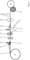
- Fig. 6 shows a schematic representation of the production process for the production of absorbent pads 6.
- a material web 2 is unwound from an original roll 10 and folded by means of a material web folding 11.
- a superabsorbent 4 in granular or powder form is applied to the material web 2 and fixed by folding the material web 2 on the material web 2.
- the superabsorbent 4 is introduced by means of a superabsorber applicator 12.
- the finished-folded material web 2 is guided through calender rolls, whereby the material web 2 is calendered and preferably the superabsorber 4 is crushed.
- the resulting absorbent core 1 is separated by means of a cutting device 14.
- Kaschiermaterial 7 is introduced from a film roll 15 in the production process and folded by a film folder 16 such that the laminating material 7 to the scattered absorbent cores 1 sets.
- an adhesive for example a hotmelt
- the product is passed through a stamping machine 18 that the absorbent pad 6 completes.
- the embossing unit 18 can effect a perforation or embossing, more preferably, a welding in the machine direction in front of and behind the individual absorbent cores 1 of the laminating material 7.
- the laminating material 7 is already perforated by the film roll 15 introduced into the process.
- the finished absorbent pads 6, which are still connected to one another, are rolled up by means of a reel 19 onto a finished roller 20.
- the absorbent pad 6 can be singled in an embodiment not shown here after the embossing unit 18, for example by a cutting device.
- the finished absorbent pads 6 can be made as a single format or as a roll.
Description
Die Erfindung betrifft ein Verfahren zur Herstellung zumindest einer Saugeinlage sowie eine Saugeinlage.The invention relates to a method for producing at least one absorbent pad and a suction pad.
Saugeinlagen, insbesondere für die Lebensmittelindustrie zur Absorption von überflüssigen Flüssigkeiten in einer Produktverpackung sind aus dem Stand der Technik bekannt. Beispielsweise beschreibt die
Aufgabe der Erfindung ist es, ein verbessertes Verfahren zur Herstellung einer Saugeinlage zur Verfügung zu stellen. Weiterhin ist Aufgabe der Erfindung eine verbesserte Saugeinlage zur Verfügung zu stellen.The object of the invention is to provide an improved process for the preparation of a absorbent insert available. Another object of the invention is to provide an improved absorbent pad.
Die Aufgabe wird erfindungsgemäß mittels eines Verfahrens zur Herstellung zumindest einer Saugeinlage nach Anspruch 1 sowie einer Saugeinlage nach Anspruch 15 gelöst. Weitere vorteilhafte Ausgestaltungen sind den nachfolgenden Beschreibungen, den Figuren sowie den Unteransprüchen zu entnehmen. Die einzelnen Merkmale der beschriebenen Ausgestaltungen sind jedoch nicht auf diese beschränkt, sondern können untereinander und mit anderen Merkmalen zu weiteren Ausgestaltungen verknüpft werden.The object is achieved by means of a method for producing at least one absorbent pad according to
Es wird ein Verfahren zur Herstellung zumindest einer Saugeinlage vorgeschlagen, das die Schritte umfasst:
- Bereitstellen einer Materialbahn,
- Aufbringen eines Superabsorbers auf die Materialbahn, wobei ein Randbereich senkrecht zur Maschinenrichtung der Materialbahn frei von Superabsorber bleibt,
- Falten der Materialbahn über den Superabsorber, so dass die Materialbahn zumindest teilweise zweilagig ausgestaltet ist, wobei die Materialbahn in einem ersten Schritt v-gefaltet wird und in einem weiteren Schritt nochmals v-gefaltet wird, wobei die Randbereiche nach der ersten Faltung im Wesentlichen übereinanderliegen,
- Falten zumindest eines superabsorberfreien Randbereichs über den zweilagigen Bereich, insbesondere so dass die Materialbahn zumindest vierlagig ausgestaltet ist,
- Kalandrieren, insbesondere satinieren, der gefalteten Materialbahn und
- Kaschieren der gefalteten Materialbahn mit einem Kaschiermaterial.
- Providing a material web,
- Applying a superabsorber to the material web, wherein an edge region perpendicular to the machine direction of the material web remains free of superabsorber,
- Folding the material web over the superabsorber, so that the material web is configured at least partially in two layers, wherein the material web is v-folded in a first step and is again v-folded in a further step, wherein the edge regions after the first folding substantially overlie each other,
- Folding at least one superabsorber-free edge region over the two-ply region, in particular so that the material web is configured at least in four layers,
- Calendering, especially satin, the folded material web and
- Laminating the folded material web with a laminating material.
Im Sinne der Erfindung ist der Randbereich ein Bereich der ungefalteten Materialbahn, der an die Ränder senkrecht zur Maschinenrichtung grenzt. Wird beispielsweise ein Rand senkrecht zur Maschinenrichtung im Wesentlichen auf den gegenüberliegenden Rand gefaltet-V-Faltung - und in einem folgenden Schritt beide Randbereiche zur Faltstelle oder Falz hin zu rück gefaltet, wird ein vierlagiger Saugkern erzeugt. Diese zweimalige V-Faltung wird im Folgenden Doppel-V-Faltung genannt.For the purposes of the invention, the edge region is a region of the unfolded material web which borders on the edges perpendicular to the machine direction. If, for example, an edge perpendicular to the machine direction is folded substantially onto the opposite edge -V-fold - and in a subsequent step both edge regions are folded back towards the fold or fold, a four-layer absorbent core is produced. This two-fold V-fold is called in the following double-V-fold.
Sind im Rahmen der Erfindung Produktionsschritte in zeitlicher Reihenfolge angegeben, so sind damit Produktionsschritte eines Abschnittes des jeweils verwendeten Rohmaterials in Maschinenrichtung zu verstehen.If production steps are indicated in chronological order within the scope of the invention, this means production steps of a section of the raw material used in the machine direction.
Im Sinne der Erfindung ist unter einer Materialbahn ein bahnförmiges Flächenprodukt aus Zellstoff, insbesondere Zellstoffwatte oderTissue, aus einem Vlies, aus einem Nonwoven und/oder aus einem gewebten oder gewirkten Material zu verstehen. Das Material umfasst in einer Ausgestaltung zumindest einen Material ausgewählt aus einer Gruppe umfassend einen Zellstoff und/oder ein thermoplastischen Kunststoff, wie beispielsweise ein Polyolefin. Vorteil des vorgeschlagenen Verfahrens ist, dass der auf die Materialbahn aufgebrachte Superabsorber durch das zweifache Falten der Materialbahn in einer Richtung senkrecht zur Maschinenrichtung nicht aus der Saugeinlage herausrieseln kann. Eine nicht erfinderische Faltung ist derart, dass entweder der Randbereich über den Superabsorber gefaltet wird, so dass der zweite Randbereich nicht vom ersten Randbereich überdeckt wird und daraufhin der zweite Randbereich über den ersten Randbereich gefaltet wird. Diese Faltung wird im Folgenden e-Faltung genannt. Eine bevorzugte Möglichkeit der Faltung ist derart, dass der erste Randbereich über den Superabsorber und den zweiten Randbereich gefaltet wird, so dass die beiden Materialbahnkanten im Wesentlichen auf- und/oder übereinander liegen und im Folgenden die beiden übereinanderliegenden Randbereiche noch einmal zurückgeschlagenen beziehungsweise gefaltet werden, so dass die Saugeinlage vierlagig ausgestaltet ist. In einer weiteren Ausgestaltung wird die Falzstelle auf die übereinander liegenden Randbereiche geschlagen. Durch die Faltvorgänge wird vorteilhafterweise erreicht, dass die nun entstandenen Lagen des Saugkerns der Saugeinlage in einem festen Verbund stehen und untereinander nicht verschiebbar sind. In einer weiteren Ausgestaltung wird der Superabso rber derart auf der Materialbahn aufgebracht und insbesondere fixiert, dass dieser im Wesentlichen in der unteren Lage der gefertigten Saugeinlage beziehungsweise des Saugkerns angeordnet ist. Weiterhin vorteilhaft wird der Superabsorber derart auf die Materialbahn aufgebracht und die Materialbahn derart gefaltet, dass der Abschnitt der Materialbahn, auf dem der Superabsorber aufgebracht ist, ausschließlich in Maschinenrichtung bewegt wird. Vorzugsweise wird dieser Abschnitt während des Faltvorgangs nicht hochgefaltet, so dass der Superabsorber im Wesentlichen durch das Falten nicht relativ zur Materialbahn bewegt wird.For the purposes of the invention, a material web is to be understood as meaning a web-shaped surface product of cellulose, in particular cellulose wadding or tissue, of a nonwoven, of a nonwoven and / or of a woven or knitted material. The material includes in one embodiment, at least one material selected from a group comprising a pulp and / or a thermoplastic, such as a polyolefin. The advantage of the proposed method is that the superabsorber applied to the material web can not trickle out of the absorbent insert due to the double folding of the material web in a direction perpendicular to the machine direction. A non-inventive folding is such that either the edge region is folded over the superabsorber, so that the second edge region is not covered by the first edge region and then the second edge region is folded over the first edge region. This convolution is called e-folding below. A preferred possibility of the folding is such that the first edge region is folded over the superabsorber and the second edge region, so that the two material web edges lie substantially on and / or one above the other and subsequently the two superimposed edge regions are folded back or folded again, so that the absorbent insert is designed in four layers. In a further embodiment, the folding point is struck on the superimposed edge regions. By folding operations is advantageously achieved that the now resulting layers of the absorbent core of the absorbent insert are in a solid composite and are not mutually displaceable. In a further embodiment, the superabsorbent is applied to the material web in such a way and in particular fixed, that it is arranged substantially in the lower layer of the fabricated absorbent insert or of the absorbent core. Further advantageously, the superabsorber is applied to the material web and the material web is folded in such a way that the portion of the material web on which the superabsorber is applied is moved exclusively in the machine direction. Preferably, this portion is not folded up during the folding process, so that the superabsorbent is not moved relative to the material web substantially by the folding.
Vorzugsweise wird die Materialbahnbreite der ungefalteten Materialbahn auf die Produktbreite des Fertigproduktes eingestellt. Insbesondere beträgt die Gesamtbreite der ungefalteten Materialbahn ein Vielfaches der Saugeinlagenbreite. Beispielsweise wenn die gewünschte Saugeinlagenbreite etwa 9 cm beträgt und der Saugkern soll aus vier Lagen Materialbahn bestehen, so beträgt die Bahnbreite der Zellstoffwattebahn dann etwa das Vierfache, also etwa 36 cm. Die Materialbahn wird hierzu gemäß der Erfindung zweimal gefaltet, das heißt es wird eine Doppel-V-Faltung ausgeführt.The material web width of the unfolded material web is preferably adjusted to the product width of the finished product. In particular, the total width of the unfolded material web is a multiple of the absorbent insert width. For example, if the desired Saugeinlagenbreite is about 9 cm and the absorbent core should consist of four layers of material web, the web width of the cellulose wadding web is then about four times, ie about 36 cm. For this purpose, the material web is folded twice according to the invention, that is to say a double-V folding is carried out.
Besonders bevorzugt ist in einer Ausgestaltung vorgesehen, dass beide Randbereiche der Materialbahn frei von Superabsorber bleiben. Dies hat den Vorteil, dass bei der vierlagigen Faltung beziehungsweise der Doppel-V-Faltung, bei der einer der Randbereiche nicht durch die Faltung vom Rest der Materialbahn umschlossen sind, kein Superabsorber an die Umgebung abgeben. Das heißt ein Herausrieselnd des Superabsorbers senkrecht zur Maschinenrichtung wird auch im fertigen Produkt vermieden. Auch wird erreicht, dass bei Verwendung des Superabsorbers insbesondere durch das Quellen des Superabsorbers, der Superabsorber im Saugkern gehalten wird.It is particularly preferred in one embodiment that both edge regions of the material web remain free of superabsorbers. This has the advantage that in the case of the four-ply folding or the double-V folding, in which one of the edge regions is not enclosed by the fold from the rest of the material web, no superabsorbent is released to the environment. That is, trickling out of the superabsorber perpendicular to the machine direction is avoided even in the finished product. It is also achieved that, when using the superabsorbent, in particular by the swelling of the superabsorber, the superabsorber is held in the absorbent core.
Besonders vorteilhaft ist in einer Ausgestaltung vorgesehen, dass der Superabsorber bei Vorsehung der erfinderischen Doppel-V-Faltung nur auf etwa einem Viertel der Bahnbreite der Materialbahn aufgebracht wird. Insbesondere wird der Superabsorber nur auf dem Bereich der Materialbahn aufgebracht, der die untere Lage der gefalteten Materialbahn bildet.It is particularly advantageous in one embodiment that the superabsorber is provided in Providence of the inventive double V-fold only to about a quarter of the web width of the web. In particular, the superabsorber is applied only on the region of the material web which forms the lower layer of the folded material web.
In einer weiteren Ausführungsform ist vorgesehen, dass der Superabsorber durch ein Auftragssystem in einen während des Faltens der Materialbahn geformten Kanal, weiter bevorzugt einen Tunnel geführt oder gefördert wird. Der durch die Materialbahn zumindest teilweise gebildete Kanal ist vorzugsweise einseitig geöffnet. Gebildet wird dieser Kanal beispielsweise durch ein Faltwerk, wobei die Faltung an der Stelle wo der Kanal gebildet ist, beziehungsweise an der der Superabsorber aufgebracht wird, nicht vollständig ausgeführt ist. Vorzugsweise wird direkt nach der Anbringung des Superabsorbers der Faltvorgang beendet und der Superabsorber ist in der gefalteten Materialbahn integriert und insbesondere vorfixiert. In einer bevorzugten Ausgestaltung wird, insbesondere mittels eines Faltwerks, ein Tunnel aus der Materialbahn gebildet. Insbesondere wird eine Faltung teilweise ausgeführt, um den Tunnel zu bilden. In diesen Tunnel wird, vorzugsweise bevor die Faltung vollständig beendet ist, Superabsorber eingebracht. Der Superabsorber wird vorzugsweise in Maschinenrichtung von Hinten in den Tunnel eingebracht. Weiterhin ist in einer Ausgestaltung vorgesehen, dass das Auftragssystem ausgestaltet ist als Lanze, Schwert, Luftstrom oder Rollband.In a further embodiment it is provided that the superabsorber is guided or conveyed by an application system into a channel formed during the folding of the material web, more preferably a tunnel. The channel formed at least partially by the material web is preferably open on one side. This channel is formed, for example, by a folding mechanism, wherein the fold is not completely executed at the point where the channel is formed or at which the superabsorber is applied. Preferably, the folding process is terminated immediately after the attachment of the superabsorber and the superabsorber is integrated in the folded material web and in particular prefixed. In a preferred embodiment, in particular by means of a folding mechanism, a tunnel is formed from the material web. In particular, a convolution partially executed to form the tunnel. Superabsorber is introduced into this tunnel, preferably before the folding is complete. The superabsorbent is preferably introduced in the machine direction from behind into the tunnel. Furthermore, it is provided in one embodiment that the application system is designed as a lance, sword, air flow or roller conveyor.
In einer weiteren bevorzugten Ausgestaltung ist vorgesehen, dass der Superabsorber derart auf der Materialbahn fixiert ist, dass er vorzugsweise auch nach der Faltung auf und/oder in der unteren Lage des gefertigten Saugkerns der Saugeinlage angeordnet ist. Hierdurch wird vorteilhafterweise erreicht, dass die aufzunehmende Flüssigkeit sofort den Superabsorber erreicht und dieser die Flüssigkeit umgehend aufnehmen kann. Weiterhin bevorzugt werden die übrigen Lagen der Materialbahn über dem Superabsorber angeordnet und sind derart ausgelegt, dass diese durch die Kapillarwirkung für ein gleichmäßiges Verteilen der Flüssigkeit im Saugkern wirken, insbesondere um die volle Wirkung des Superabsorbers ausschöpfen zu können.In a further preferred embodiment, it is provided that the superabsorber is fixed on the material web in such a way that it is preferably arranged on and / or in the lower layer of the manufactured absorbent core of the absorbent insert even after folding. This advantageously ensures that the liquid to be absorbed immediately reaches the superabsorber and this can absorb the liquid immediately. Further preferably, the remaining layers of the material web are arranged above the superabsorber and are designed such that they act by the capillary action for a uniform distribution of the liquid in the absorbent core, in particular to be able to exploit the full effect of the superabsorbent can.
Werden im Rahmen der Erfindung die Begriffe "unten" und "oben" verwendet, so geben diese lediglich relative Bezüge zueinander an. Vorzugsweise verweisen Richtungsbezeichnungen auf die Richtungen im Produktionsprozess, bevorzugt bezogen auf die Maschinenrichtung.If the terms "bottom" and "top" are used in the context of the invention, these merely indicate relative references to one another. Directional designations preferably refer to the directions in the production process, preferably in relation to the machine direction.
Im Rahmen der Erfindung ist unter einem Saugkern die gefaltete Materialbahn zu verstehen, die insbesondere auch den Superabsorber einschließt. Die Saugeinlage hingegen umfasst den Saugkern und darüber hinaus noch weitere Komponenten, wie beispielsweise eine Kaschierung.In the context of the invention, a suction core is to be understood as the folded material web, which in particular also includes the superabsorber. By contrast, the absorbent insert comprises the absorbent core and, in addition, further components, such as a lamination.
In einer weiteren Ausführungsform ist vorgesehen, dass der Superabsorber beim Kalandrieren des Saugkerns zerkleinert, insbesondere zermahlen, wird. Das Kalandrieren beziehungsweise Satinieren des Saugkerns hat den Vorteil, dass eine kompakte Einheit von Materialbahn und Superabsorber erzielt wird, wobei sich der zerkleinerte Superabsorber in der Materialbahn verankert. Weiterhin vorteilhaft an der Zerkleinerung des Superabsorbers ist, dass dieser eine größere Oberfläche zur Aufnahme von Flüssigkeit aufweist, als der unzerkleinerte Superabsorber. Weiterhin vorteilhaft ist, dass der Superabsorber relativ grob auf die Materialbahn aufgebracht werden kann, was eine Handhabung und insbesondere eine höhere Maschinengeschwindigkeit erlaubt; dennoch sind die Vorteile eines relativ feinkörnigen Superabsorbers im Saugkern beziehungsweise in der Saugeinlage nutzbar. Weiter vorteilhaft ist in einer Ausgestaltung vorgesehen, dass der Superabsorber mittels der Kalandrierung in der Materialbahn verankert wird. Bevorzugt erfolgt eine mechanische Verhaftung zwischen dem Superabsorber und dem Material der Bahn.In a further embodiment, it is provided that the superabsorber is comminuted, in particular comminuted, during calendering of the absorbent core. The calendering or calendering of the absorbent core has the advantage that a compact unit of material web and superabsorber is achieved, wherein the comminuted superabsorber in anchored the material web. Another advantage of the comminution of the superabsorber is that it has a larger surface area for receiving liquid than the uncrushed superabsorber. It is also advantageous that the superabsorber can be applied relatively coarsely to the material web, which allows handling and in particular a higher machine speed; Nevertheless, the advantages of a relatively fine-grained superabsorbent in the absorbent core or in the absorbent insert can be used. It is also advantageous in one embodiment that the superabsorber is anchored by calendering in the material web. Preferably, there is a mechanical attachment between the superabsorbent and the material of the web.
In einer weiteren Ausgestaltung wird vorgeschlagen, dass die Materialbahn angefeuchtet wird, insbesondere bevor der Superabsorber auf die Materialbahn aufgebracht wird. Dies hat den Vorteil, dass der Superabsorber aktiviert wird und sich in den Fasern der Materialbahn verankert. In einer weiteren Ausgestaltung ist vorgesehen, dass die Materialbahn im Produktionsprozess trocken bleibt, das heißt einen Feuchtegehalt nach DIN 54540 Teil 4, Stand Juni 1989, von etwa 0 % bis etwa 10 %, bevorzugt etwa 3 % bis etwa 8 %, aufweist.In a further embodiment, it is proposed that the material web be moistened, in particular before the superabsorber is applied to the material web. This has the advantage that the superabsorbent is activated and anchored in the fibers of the material web. In a further embodiment, it is provided that the material web remains dry in the production process, that is, a moisture content according to DIN 54540
In einer weiteren Ausgestaltung ist vorgesehen, dass das Kaschiermaterial zumindest ein Material ausgewählt aus einer Gruppe umfassend eine Folie, ein Gewebe und/oder ein Gewirke ist. Insbesondere umfasst das Kaschiermaterial Polyethylen, Polypropylen und/oder Papier. Weiterhin vorteilhafterweise wird gemäß einer Ausführungsform das Kaschiermaterial aus einem Gewebe oder Gewirke hergestellt. Weiterhin bevorzugt ist das Kaschiermaterial derart gestaltet, dass dieses hydrophil wirkt. Beispielsweise umfasst das Kaschiermaterial eine Folie mit Ventilwirkung und/oder ein hydrophil ausgestaltetes Nonwoven-Material, damit die aufzunehmende Flüssigkeit den Saugkern möglichst schnell erreicht und durch den eingelagerten Superabsorber gebunden wird. Eine Ventilwirkung des Kaschiermaterials wird insbesondere durch Öffnungen erzielt, die beispielsweise mittels einer Nadelung erzeugt werden, die jeweils eine Kapillarwirkung aufweisen.In a further embodiment, it is provided that the laminating material is at least one material selected from a group comprising a film, a woven fabric and / or a knitted fabric. In particular, the laminating material comprises polyethylene, polypropylene and / or paper. Further advantageously, according to one embodiment, the laminating material is produced from a woven or knitted fabric. Further preferably, the laminating material is designed such that it acts hydrophilic. For example, the laminating material comprises a film with a valve effect and / or a hydrophilically configured nonwoven material, so that the liquid to be absorbed reaches the absorbent core as fast as possible and is bound by the superabsorber embedded in it. A valve action of the laminating material is achieved in particular by openings which are produced, for example, by means of a needling, which each have a capillary action.
In einer Ausführungsform ist vorgesehen, dass das Kaschiermaterial beispielsweise über Formschulterbleche als Schlauch geformt und um den Saugkern gelegt wird. Vorteilhafterweise wird das Kaschiermaterial zumindest teilweise mit einem Kleber beispielsweise einem Hotmelt benetzt. Weiterhin vorteilhaft wird durch ein anschließendes Faltwerk beispielweise in Verbindung mit einem Prägewerk ein Verbund des Kaschiermaterials mit dem Saugkern gebildet. Durch diesen Fertigungsvorgang ist der Saugkern vorteilhafterweise ringsum verschlossen, so dass gänzlich verhindert wird, dass Superabsorber aus der Saugeinlage heraustritt.In one embodiment, it is provided that the laminating material is formed as a tube, for example via Formschulterbleche and placed around the absorbent core. Advantageously, the laminating material is wetted at least partially with an adhesive, for example a hotmelt. Further advantageous is formed by a subsequent folding work, for example in conjunction with a stamping machine, a composite of Kaschiermaterials with the absorbent core. By this manufacturing process, the absorbent core is advantageously closed all around, so that it is completely prevented that superabsorbent comes out of the absorbent pad.
In einer weiteren Ausführungsform ist vorgesehen, dass das Kaschiermaterial über insbesondere Formschulterbleche als Halbschlauch gebildet wird und teilweise um den Saugkern gelegt wird. Vorzugsweise wird in einem weiteren Schritt oder gleichzeitig eine weitere Bahn umfassend eine Folie, ein Nonwoven und/oder ein nassfestes Papier als Abdecklage aufkaschiert.In a further embodiment it is provided that the laminating material is formed as a half-tube in particular via form shoulder plates and is partially laid around the absorbent core. Preferably, in a further step or simultaneously a further web comprising a film, a nonwoven and / or a wet-strength paper is laminated on as a cover layer.
In einer Ausführungsform des Verfahrens ist vorgesehen, dass das Kaschiermaterial eine Anzahl von Saugeinlagen verbindet. Unter anderem ist vorgesehen, dass das Kaschiermaterial Perforierungen zwischen den Saugeinlagen aufweist. Gemäß einer Ausgestaltung ist vorgesehen, dass die Saugkerne vor der Kaschierung von einander getrennt werden, beziehungsweise die gefaltete und gegebenenfalls kalandrierte Materialbahn geschnitten wird und die einzelnen Saugkerne von einander beabstandet sind, dass diese vorzugsweise von dem Kaschiermaterial umschlossen werden und in dem nachfolgenden Schritten die Saugeinlagen vereinzelbar sind.In one embodiment of the method it is provided that the laminating material connects a number of absorbent pads. Among other things, it is provided that the laminating material has perforations between the absorbent pads. According to one embodiment, it is provided that the absorbent cores are separated from each other before laminating, or the folded and optionally calendered material web is cut and the individual absorbent cores are spaced from each other, that they are preferably enclosed by the laminating material and in the subsequent steps the absorbent pads are singular.
Die miteinander insbesondere über das Kaschiermaterial verbundenen Saugeinlagen werden gemäß einer weiteren Ausführungsform aufgerollt. In einer weiteren Ausgestaltung ist vorgesehen, dass die einzelnen Saugeinlagen von einander getrennt werden, in dem das Kaschiermaterial durchtrennt wird.The absorbent pads joined together in particular via the laminating material are rolled up according to a further embodiment. In a further embodiment, it is provided that the individual absorbent pads are separated from each other, in which the laminating material is severed.
Eine weitere Ausführungsform sieht vor, dass ein Saugkern umfassend die Materialbahn und den Superabsorber, zumindest in Maschinenrichtung kürzer ist als die Kaschierung.A further embodiment provides that a absorbent core comprising the material web and the superabsorber, at least in the machine direction is shorter than the lamination.
Weiterhin wird eine Saugeinlage mit einem Saugkern und einem Kaschiermaterial vorgeschlagen, wobei der Saugkern eine gefaltete Materialbahn und einen Superabsorber aufweist.Furthermore, a suction insert with a absorbent core and a laminating material is proposed, wherein the absorbent core has a folded material web and a superabsorber.
Die Materialbahn ist um den auf der Materialbahn aufliegenden Superabsorber herum gefaltet, so dass der Superabsorber von zumindest einer Seite zumindest dreilagig, vorzugsweise vierlagig von der Materialbahn bedeckt ist, wobei die Materialbahn doppelt v-gefaltet ist, wobei der Saugkern kalandriert ist und das Kaschiermaterial um den Saugkern gelegt ist.The material web is folded around the superabsorber resting on the material web, so that the superabsorber is covered by the material web at least three sides, preferably four layers, the material web being double-folded, the absorbent core being calendered and the lining material being calendered the absorbent core is placed.
Vorteilhafterweise wird die Saugeinlage für Lebensmittel insbesondere für Lebensmittelverpackung oder für industrielle Anwendungen, bei der eine Flüssigkeitsaufnahme vorgesehen ist, verwendet. Gemäß einer Ausgestaltung ist über die Aufbringung von Superabsorbern und der Auswahl einer Zellstoffwatte und/oder eines Vlies für die Materialbahn eine Flüssigkeitsaufnahme eingestellt. Weiterhin vorteilhaft ist das Produktgewicht über die Masse der Materialbahn beziehungsweise Zellstoffwatte und die Menge des aufgebrachten Superabsorbers sowie des eingesetzten Kaschiermaterials eingestellt. Weiterhin ist gemäß einer Ausgestaltung vorgesehen, dass das Volumen des Saugkerns der Saugeinlage über den Kreppungsgrad der Zellstoffwatte der Materialbahn, der Anzahl der Faltungen der Materialbahn, der Menge des Superabsorber und/oder der nachgeschalteten Satinage eingestellt ist.Advantageously, the absorbent pad for food is used in particular for food packaging or for industrial applications, in which a liquid intake is provided. According to one embodiment, a liquid absorption is set by the application of superabsorbers and the selection of a cellulose wadding and / or a fleece for the material web. Furthermore, the product weight is advantageously set via the mass of the material web or cellulose wadding and the amount of superabsorber applied and of the laminating material used. Furthermore, according to an embodiment, it is provided that the volume of the absorbent core of the absorbent pad is set via the degree of crepe of the cellulose wadding of the material web, the number of folds of the material web, the amount of superabsorber and / or the downstream calendering.
In einer Ausgestaltung ist vorgesehen, dass der Superabsorber zumindest ein querverbundenes Natriumpolycarbonat umfasst. Weiterhin ist in einer weiteren Ausgestaltung vorgesehen, dass der Superabsorber eine Zentrifugenspeicherfähigkeit (centrifuge retention capacity) nach WSP 241.3.R (12) von etwa 20 g/g bis etwa 45 g/g, bevorzugt etwa 30 g/g bis etwa 40 g/g, weiter bevorzugt etwa 32 g/g bis etwa 34 g/g, weiter bevorzugt etwa 33,5 g/g aufweist. Weiterhin ist gemäß einer Variante vorgesehen, dass der Superabsorber eine Absorptionsrate unter einem Druck von 4,83 kPa (0,7 psi) nach WSP 242.3.R (12) von etwa 15 g/g bis etwa 35 g/g, bevorzugt etwa 20 g/g bis etwa 25 g/g, weiter bevorzugt etwa 22 g/g aufweist. Weiterhin ist gemäß einer Ausgestaltung vorgesehen, dass der Superabsorber eine Partikelgrößenverteilung nach WSP 220.3.R3 (12) von größer 300 µm entspricht etwa 40 % bis etwa 60 %, bevorzugt etwa 45 % bis etwa 55 %, weiter bevorzugt etwa 50 %, vorzugsweise größer 850 µm entspricht etwa 0,1 % bis etwa 1,5 %, bevorzugt 0 % bis etwa 0,5 %, weiter bevorzugt maximal 1 % aufweist. In einer weiteren bevorzugten Ausgestaltung ist vorgesehen, dass der Superabsorber ein Superabsorber der Firma Evonik Industries AG in 47508 Krefeld, Deutschland, mit dem Markennamen "FAVOR SXM 9155" ist. Weiterhin vorteilhaft ist der Superabsorber ein Superabsorber mit etwa den Kenndaten des "FAVOR SXM 9155" von November 2013.In one embodiment, it is provided that the superabsorber comprises at least one cross-linked sodium polycarbonate. Furthermore, in a further embodiment, it is provided that the superabsorber has a centrifuge retention capacity according to WSP 241.3.R (12) of about 20 g / g to about 45 g / g, preferably about 30 g / g to about 40 g / g, more preferably about 32 g / g to about 34 g / g, more preferably about 33.5 g / g. Furthermore, according to a variant, it is provided that the superabsorber has an absorption rate under a pressure of 4.83 kPa (0.7 psi) according to WSP 242.3.R (12) of about 15 g / g to about 35 g / g, preferably about 20 g / g to about 25 g / g, more preferably about 22 g / g. Furthermore, according to one embodiment, it is provided that the superabsorber has a particle size distribution according to WSP 220.3.R3 (12) of greater than 300 μm corresponds to about 40% to about 60%, preferably about 45% to about 55%, more preferably about 50%, preferably greater 850 μm corresponds to about 0.1% to about 1.5%, preferably 0% to about 0.5%, more preferably at most 1%. In a further preferred embodiment, it is provided that the superabsorber is a superabsorbent from Evonik Industries AG in 47508 Krefeld, Germany, with the trade name "FAVOR SXM 9155". The superabsorber is also advantageously a superabsorber with approximately the characteristics of the "FAVOR SXM 9155" from November 2013.
Die Materialbahn umfasst vorzugsweise eine Hochkreppprägewatte, eine Prägewatte und/oder eine Formatware. Vorzugsweise ist die Materialbahn hochgebleicht.The material web preferably comprises a high crepe embossing mat, an embossing mat and / or a format product. Preferably, the material web is bleached.
Ist im Rahmen der Erfindung der Begriff "etwa" verwendet, insbesondere in Bezug auf Werte und/oder Wertebereiche, so ist darunter ein Toleranzbereich zu verstehen, den der Fachmann auf diesem Gebiet für üblich erachtet, insbesondere ist ein Toleranzbereich von +/- 20 %, bevorzugt +/- 10 %, noch weiter bevorzugt +/- 5 %, vorgesehen. Ist im Rahmen der Erfindung der Begriff "im Wesentlichen" verwendet, so ist damit eine Toleranz zu verstehen, unter der der Fachmann unter technischen und wirtschaftlichen Gesichtspunkten das angegebene Merkmal als solches erkennt.If the term "about" is used in the context of the invention, in particular with regard to values and / or value ranges, this is to be understood as meaning a tolerance range which the person skilled in the art would consider customary, in particular a tolerance range of +/- 20%. , preferably +/- 10%, more preferably +/- 5%, provided. If the term "substantially" is used in the context of the invention, then it is to be understood as a tolerance under which the person skilled in the art recognizes the specified feature as such from a technical and economic point of view.
In einer weiteren Ausgestaltung ist vorgesehen, dass die Flächenmasse der Materialbahn bevor diese zum Saugkern verarbeitet wird nach DIN EN 12625 von 2011 zwischen etwa 18 g/m2 und etwa 30 g/m2, bevorzugt etwa 20 g/m2 bis etwa 25 g/m2 umfasst. In einer weiteren Ausgestaltung ist vorgesehen, dass die Flächenmasse nach DIN EN126256 von 2011 zwischen etwa 180 g/m2 und etwa 260 g/m2, bevorzugt etwa 200 g/m2 bis etwa 250 g/m2, weiter bevorzugt etwa 220 g/m2 bis etwa 260 g/m2 beträgt. Vorzugsweise beträgt die Flächenmasse etwa 210 g/m2 bis etwa 230 g/m2. Der Bereich zwischen etwa 18 g/m2 und etwa 30 g/m2 der Flächenmasse für die Materialbahn bezieht sich insbesondere auf einlagiges Hochkrepp oder Prägewatte oder Formatware. Der Bereich zwischen etwa 180 g/m2 und etwa 260 g/m2 bezieht sich insbesondere auf Prägewatte, Hochkrepp oder Formatware, die mehrlagig einem Kalendar vor der Weiterverarbeitung zum Saugkern zugeführt wurde. Vorzugsweise weist die Materialbahn vor der Weiterverarbeitung eine Wasseraufnahme bei 500 g Belastung von mindestens 17 g, vorzugsweise etwa 17 g bis etwa 20 g, weiter bevorzugt etwa 17 g bis etwa 50 g auf. Weiterhin bevorzugt weist die Materialbahn vor Weiterverarbeitung eine Wasseraufnahme bei 1000 g Belastung von mindestens 14 g, bevorzugt etwa 14 g bis etwa 20 g, weiter bevorzugt etwa 14 g bis etwa 50 g auf.In a further embodiment, it is provided that the basis weight of the material web before it is processed into the absorbent core according to DIN EN 12625 of 2011 between about 18 g / m 2 and about 30 g / m 2 , preferably about 20 g / m 2 to about 25 g / m 2 includes. In a further embodiment it is provided that the basis weight according to DIN EN126256 of 2011 between about 180 g / m 2 and about 260 g / m 2 , preferably about 200 g / m 2 to about 250 g / m 2 , more preferably about 220 g / m 2 to about 260 g / m 2 . Preferably, the basis weight is about 210 g / m 2 to about 230 g / m 2 . The range between about 18 g / m 2 and about 30 g / m 2 of the basis weight for the material web refers in particular to single-ply high crepe or Prägewatte or format goods. The area between about 180 g / m 2 and about 260 g / m 2 refers in particular to Prägewatte, high crepe or format goods, which was supplied in multiple layers a calendar before further processing to the absorbent core. Preferably, the material web before further processing, a water absorption at 500 g load of at least 17 g, preferably about 17 g to about 20 g, more preferably about 17 g to about 50 g. Further preferably, the material web before further processing, a water absorption at 1000 g load of at least 14 g, preferably about 14 g to about 20 g, more preferably about 14 g to about 50 g.
Vorzugsweise weist die Materialbahn eine freie Wasseraufnahme von zumindest 21 g, bevorzugt etwa 21 g bis etwa 30 g, weiter bevorzugt etwa 21 g bis etwa 50 g auf.The material web preferably has a free water absorption of at least 21 g, preferably from about 21 g to about 30 g, more preferably from about 21 g to about 50 g.
Zur Bestimmung der Wasseraufnahme der Materialbahn wird eine Probe der Materialbahn von 80 mm * 120 mm, die vorher auf 0,01 g genau eingewogen wurde - was die klimatisierte Masse Mk ist, vollflächig mit der Saugseite nach unten in eine mit entionisiertem Wasser gefüllte Schale gelegt und vollständig untergetaucht. Die Bewässerungsdauer beträgt 60 Sekunden. Die Probe befindet sich während des Wässerns unterhalb des Wasserspiegels, wobei ein allseitiger Wasserzutritt zur Probe sichergestellt ist. Nach der Bewässerungszeit von 60 Sekunden wird die Probe mit der Schmalseite parallel zu einer Tischoberfläche mit einer Breitklemme für 30 Sekunden zum Abtropfen aufgehangen. Hierbei wird ein Übereinanderschlagen der Probe vermieden. Nach einer Abtropfzeit von 30 Sekunden wird die Probe auf 0,01 g genau ausgewogen - was der Masse nass Mn entspricht. Die Die freie Wasseraufnahme WA berechnet sich dann wie folgt: ![]()
![]()
Zur Bestimmung der Wasseraufnahme WAbel unter Belastung wird nach einer Bewässerungsdauer von 30 Sekunden und einer Ablaufzeit von 15 Sekunden eine Probe mit den Maßen 80 mm * 120 mm bestimmt. Die Probe wird in einer Polystyrolschale mit der Saugseite nach unten eingelegt. Schale und Proben werden gemeinsam zur Bestimmung der Masse Mk auf 0,01 g genau ausgewogen. Anschließend wird die Probe mit 20 g entionisiertem Wasser umspült. Nachdem eine Flüssigkeitsmenge von der Probe aufgenommen wurde, wird in das Gewicht von 500 g beziehungsweise 1000 g vollflächig aufgebracht. Die Probe verbleibt 30 Sekunden in horizontaler Stellung. Im Folgenden wird die Schale in Schrägstellung gebracht, das heißt mit einer Ablaufvorrichtung mit 25 °Neigungswinkel aufgesetzt. Nach 50 Sekunden wird die Flüssigkeitsmenge die sich im Schalenboden gesammelt hat mit einem Saugtuch abgesaugt, die Probe wird entlastet und zur Bestimmung der Masse Mn auf 0,01 g gewogen. Die Wasseraufnahme unter Belastung WAbel berechnet sich dann wie folgt: ![]()
![]()
In einer weiteren Ausgestaltung ist vorgesehen, dass Superabsorber von zumindest einer Seite zumindest dreilagig von der Materialbahn bedeckt ist.In a further embodiment it is provided that superabsorber is covered by at least three sides of the material web from at least one side.
Eine weitere Variante sieht vor, dass die Materialbahnen doppelt-V-gefaltet ist. Wie bereits weiter oben erwähnt, hat diese doppelte V-Faltung, das heißt die Materialbahn wird vorgefaltet und in einem nachfolgenden Schritt wird die vorgefaltete Materialbahn nochmals V-gefaltet, den Vorteil, dass der Superabsorber sicher in den Saugkern eingeschlossen ist.Another variant provides that the material webs double-V-folded. As already mentioned above, this double V-fold, that is, the material web is prefolded and in a subsequent step, the prefolded web is again V-folded, the advantage that the superabsorber is securely enclosed in the absorbent core.
Zur weiteren Vermeidung des Heraustretens des Superabsorbers aus der Saugeinlage und zur Vermeidung einer Kontamination von Lebensmitteln mit Superabsorber ist der Saugkern mit einem Kaschiermaterial kaschiert. Vorzugsweise ist das Kaschiermaterial zumindest ein Material ausgewählt aus einer Gruppe umfassend eine Folie, ein Gewebe und/oder ein Gewirke. Beispielsweise umfasst das Kaschiermaterial Polyethylen, Polypropylen und/oder Papier.To further avoid the emergence of the superabsorber from the absorbent pad and to avoid contamination of foods with superabsorbent the absorbent core is laminated with a laminating material. Preferably, the laminating material is at least one material selected from a group comprising a film, a woven fabric and / or a knitted fabric. For example, the laminating material comprises polyethylene, polypropylene and / or paper.
Gemäß einer weiteren Ausführungsform ist vorgesehen, dass die Saugeinlage mit weiteren Saugeinlagen mittels der Kaschierung verbunden ist.According to a further embodiment it is provided that the absorbent insert is connected to further absorbent pads by means of the lamination.
Dies wird insbesondere dadurch erreicht, dass die Kaschierung ein fortlaufendes Material ist, das bei der Produktion um die vereinzelten Saugkerne gelegt wird und/vorzugsweise geprägt oder derart verschweißt wird, dass die einzelnen Saugeinlagen nicht von einander oder nicht vollständig von einan der getrennt sind.This is achieved in particular by the fact that the lamination is a continuous material, which is placed in the production of the scattered absorbent cores and / preferably embossed or welded so that the individual absorbent pads are not separated from each other or not completely from einan.
Weitere vorteilhafte Ausgestaltungen gehen aus den nachfolgenden Zeichnungen hervor. Die dort dargestellten Weiterbildungen sind jedoch nicht beschränkend auszulegen, vielmehr können die dort beschriebenen Merkmale untereinander und mit den oben beschriebenen Merkmalen zur weiteren Ausgestaltungen kombiniert werden.Further advantageous embodiments will become apparent from the following drawings. However, the developments shown there are not construed restrictive, but rather the features described there can be combined with each other and with the features described above for further embodiments.
Des Weiteren sei darauf verwiesen, dass die in der Figurenbeschreibung angegebenen Bezugszeichen den Schutzbereich der vorliegenden Erfindung nicht beschränken, sondern lediglich auf die in den Figuren gezeigten Ausführungsbeispiele verweisen. Gleiche Teile oder Teile mit gleicher Funktion weisen im Folgenden die gleichen Bezugszeichen auf. Es zeigen:
- Fig. 1
- die Faltung eines Saugkerns in Doppel-V-Faltung;
- Fig. 2
- die Faltung eines nicht erfinderischen Saugkerns in e-Faltung;
- Fig. 3
- ein schematischen Querschnitt durch eine erste Saugeinlage;
- Fig. 4
- einen schematischen Querschnitt durch eine zweite Saugeinlage;
- Fig. 5
- eine Aufsicht auf eine Saugeinlage; und
- Fig. 6
- eine schematische Darstellung des Produktionsprozesses zur Herstellung einer Saugeinlage.
- Fig. 1
- the folding of a absorbent core in double V-fold;
- Fig. 2
- the folding of a non-inventive absorbent core in e-fold;
- Fig. 3
- a schematic cross section through a first absorbent pad;
- Fig. 4
- a schematic cross section through a second absorbent pad;
- Fig. 5
- a view of a suction pad; and
- Fig. 6
- a schematic representation of the production process for producing a suction pad.
Claims (14)
- Method for manufacturing at least one absorbent pad (6) comprising the steps of providing a material web (2),
applying a super absorbent (4) onto the material web (2), wherein at least one margin area (5) perpendicular to the machine direction of the material web (2) remains free of the super absorbent (4),
folding of the material web (2) via the superabsorbent (4), in a way that the material web (2) is at least partially formed in two layers,
folding at least of the at least one superabsorbent-free margin area (5) over the two-layered area, wherein the material web (2) is folded in v-form in the first step and folded in v-form again in a further step, wherein the margin areas (5) are substantially lying on top of each other after the first folding,
calendering of the folded material web (2),
laminating of the folded material web (2) with a laminating material (7). - Method according to claim 1, characterized in that the two margin areas (5) of the material web (2) remain free of superabsorbent (4).
- Method according to one of the preceding claims, characterized in that the superabsorbent (4) is crushed during calendering.
- Method according to one of the preceding claims, characterized in that the material web (2) is moistened.
- Method according to one of the preceding claims, characterized in that the laminating material (7) is at least a material selected from a group comprising a film, a tissue, a fleece and/or a knitting.
- Method according to claim 5, characterized in that the laminating material (7) comprises a hydrophobe material and/or a material having a valve effect.
- Method according to one of the preceding claims, characterized in that the laminating material (7) connects a number of absorbent pads (6).
- Method according to claim 7, characterized in that a number of absorbent pads (6) is rolled up.
- Method according to one of the preceding claims, characterized in that the single absorbent pads (6) are separated of each other by cutting through the laminating material (7).
- Method according to one of the preceding claims, characterized in that the absorbent core (1), comprising the material web (2) and the super absorbent (4), is shorter then the lamination (7) in machine direction.
- Absorbent pad (6), manufactured according to a method according to one or more of the claims 1 to 10, with an absorbent core (1) and a laminating material (7), wherein the absorbent core (1) has a folded material web (2) and a super absorbent (4), wherein the material web (2) is folded around the superabsorbent (4) resting on the material web (2) in a way that the superabsorbent (4) is on at least one side covered by at least three layers of the material web (2), wherein the material web (2) is double fold in v-form, wherein the absorbent core (1) is calendered and the laminating material (7) is applied around the absorbent core (1).
- Absorbent pad (6) according to claim 11, characterized in that the absorbent pad (6) comprises only one layer of the super absorbent (4).
- Absorbent pad (6) according to one of the claims 11 or 12, characterized in that the laminating material (7) comprises at least one material selected from a group comprising a film, a tissue, a fleece and/or a knitting.
- Absorbent pad (6) according to one of the claims 11 to 13, characterized in that the absorbent pad (6) is connected with further absorbent pads (6) by means of the lamination (7).
Priority Applications (1)
| Application Number | Priority Date | Filing Date | Title |
|---|---|---|---|
| PL15723502T PL3145464T3 (en) | 2014-05-19 | 2015-05-18 | Method for producing at least one suction insert, and a suction insert |
Applications Claiming Priority (2)
| Application Number | Priority Date | Filing Date | Title |
|---|---|---|---|
| DE102014007209.6A DE102014007209A1 (en) | 2014-05-19 | 2014-05-19 | Process for the preparation of at least one absorbent pad and a absorbent pad |
| PCT/EP2015/060901 WO2015177096A1 (en) | 2014-05-19 | 2015-05-18 | Method for producing at least one suction insert, and a suction insert |
Publications (2)
| Publication Number | Publication Date |
|---|---|
| EP3145464A1 EP3145464A1 (en) | 2017-03-29 |
| EP3145464B1 true EP3145464B1 (en) | 2017-11-22 |
Family
ID=53189814
Family Applications (1)
| Application Number | Title | Priority Date | Filing Date |
|---|---|---|---|
| EP15723502.9A Active EP3145464B1 (en) | 2014-05-19 | 2015-05-18 | Method for producing at least one suction insert, and a suction insert |
Country Status (5)
| Country | Link |
|---|---|
| EP (1) | EP3145464B1 (en) |
| DE (1) | DE102014007209A1 (en) |
| ES (1) | ES2660337T3 (en) |
| PL (1) | PL3145464T3 (en) |
| WO (1) | WO2015177096A1 (en) |
Families Citing this family (1)
| Publication number | Priority date | Publication date | Assignee | Title |
|---|---|---|---|---|
| DE102022104084A1 (en) * | 2022-02-22 | 2023-08-24 | Andreas Ramthun | Use of at least one layer of cellulose wadding for the manufacture of formed products |
Family Cites Families (9)
| Publication number | Priority date | Publication date | Assignee | Title |
|---|---|---|---|---|
| JP3675601B2 (en) * | 1996-09-12 | 2005-07-27 | ユニ・チャーム株式会社 | Absorber |
| US6066775A (en) * | 1997-10-09 | 2000-05-23 | Amir Paper Products | Absorbent core and method for construction thereof |
| US7294591B2 (en) * | 2002-12-13 | 2007-11-13 | Kimberly-Clark Worldwide, Inc. | Absorbent composite including a folded substrate and an absorbent adhesive composition |
| DE102004043289A1 (en) | 2004-09-08 | 2006-03-09 | Gevas Gmbh | Liquid-absorbing inlays, useful e.g. in hygienic products or food packaging, produced by forming spaced pads of cellulosic material on lower sheet, adhering upper sheet to enclose pads and cutting |
| WO2006038264A1 (en) * | 2004-09-30 | 2006-04-13 | Daio Paper Corporation | Absorptive article |
| US20060204723A1 (en) * | 2005-03-11 | 2006-09-14 | Rachelle Bentley | Method of making absorbent core structures |
| US20080167634A1 (en) * | 2005-03-23 | 2008-07-10 | Takuya Kouta | Absorbent Article |
| US8373016B2 (en) * | 2006-03-23 | 2013-02-12 | Kao Corporation | Absorbent member and method of producing the same |
| CN201980578U (en) * | 2010-11-24 | 2011-09-21 | 杭州珂瑞特机械制造有限公司 | Water absorption pad |
-
2014
- 2014-05-19 DE DE102014007209.6A patent/DE102014007209A1/en not_active Withdrawn
-
2015
- 2015-05-18 ES ES15723502.9T patent/ES2660337T3/en active Active
- 2015-05-18 PL PL15723502T patent/PL3145464T3/en unknown
- 2015-05-18 WO PCT/EP2015/060901 patent/WO2015177096A1/en active Application Filing
- 2015-05-18 EP EP15723502.9A patent/EP3145464B1/en active Active
Also Published As
| Publication number | Publication date |
|---|---|
| ES2660337T3 (en) | 2018-03-21 |
| EP3145464A1 (en) | 2017-03-29 |
| PL3145464T3 (en) | 2018-04-30 |
| WO2015177096A1 (en) | 2015-11-26 |
| DE102014007209A1 (en) | 2015-11-19 |
Similar Documents
| Publication | Publication Date | Title |
|---|---|---|
| DE60023431T2 (en) | Absorbent article with several highly absorbent zones | |
| DE2718344C2 (en) | Sanitary napkin and method of making the same | |
| DE60019210T3 (en) | THIN WOMEN'S BAND WITH CONTROLLED FORMING IN USE | |
| DE69915022T2 (en) | Absorbent article with a highly absorbent zone | |
| EP0012295B1 (en) | Sanitary towel | |
| DE2535058C2 (en) | Disposable diaper | |
| DE2658604C2 (en) | Absorbent pad for underwear and process for their manufacture | |
| EP2503974B1 (en) | Absorbent structure | |
| DE60036840T2 (en) | Thin sanitary napkin with controlled deformability during use | |
| DE60204512T2 (en) | Production method for absorbent articles with side panels | |
| EP2903570B1 (en) | Sanitary bag | |
| DE69838092T2 (en) | A method of producing a fibrous layer for an absorbent article | |
| DE2432722A1 (en) | MULTILAYER DIAPER AND METHOD OF MANUFACTURING IT | |
| DE2047439A1 (en) | Disposable diaper | |
| DE19739210B4 (en) | Absorbent article, such as a sanitary napkin, incontinence guard, panty liner or the like | |
| DE60207427T2 (en) | ABSORBENT ARTICLE WITH OPENINGS IN THE SUCTION BODY | |
| WO1996000625A2 (en) | Device and process for producing an undulating strip and absorbent product containing an undulating strip | |
| EP2701646A1 (en) | Wound care article having a pattern of incisions and/or punchings | |
| CH661432A5 (en) | METHOD FOR PRODUCING A MULTILAYER SUCTION CUSHION FOR HYGIENIC AND MEDICAL DISPOSABLE ARTICLES. | |
| DE19938437B4 (en) | Use of Absorbent Articles and their Use | |
| DE112015006462T5 (en) | FLEXIBLE ABSORBENT ARTICLE WITH A LACQUERED ABSORBENT LAYER | |
| DE112015006515T5 (en) | ABSORBENT ARTICLE WITH NON-INTEGRATED SIDE COVERS AND NON INTEGRATED WINGS | |
| DE60019856T3 (en) | Compression resistant sanitary napkin | |
| EP3145464B1 (en) | Method for producing at least one suction insert, and a suction insert | |
| DE60023075T2 (en) | Thin, flexible sanitary napkin |
Legal Events
| Date | Code | Title | Description |
|---|---|---|---|
| PUAI | Public reference made under article 153(3) epc to a published international application that has entered the european phase |
Free format text: ORIGINAL CODE: 0009012 |
|
| 17P | Request for examination filed |
Effective date: 20161011 |
|
| AK | Designated contracting states |
Kind code of ref document: A1 Designated state(s): AL AT BE BG CH CY CZ DE DK EE ES FI FR GB GR HR HU IE IS IT LI LT LU LV MC MK MT NL NO PL PT RO RS SE SI SK SM TR |
|
| AX | Request for extension of the european patent |
Extension state: BA ME |
|
| GRAP | Despatch of communication of intention to grant a patent |
Free format text: ORIGINAL CODE: EPIDOSNIGR1 |
|
| GRAJ | Information related to disapproval of communication of intention to grant by the applicant or resumption of examination proceedings by the epo deleted |
Free format text: ORIGINAL CODE: EPIDOSDIGR1 |
|
| DAV | Request for validation of the european patent (deleted) | ||
| DAX | Request for extension of the european patent (deleted) | ||
| INTG | Intention to grant announced |
Effective date: 20170512 |
|
| INTC | Intention to grant announced (deleted) | ||
| GRAP | Despatch of communication of intention to grant a patent |
Free format text: ORIGINAL CODE: EPIDOSNIGR1 |
|
| INTG | Intention to grant announced |
Effective date: 20170707 |
|
| GRAS | Grant fee paid |
Free format text: ORIGINAL CODE: EPIDOSNIGR3 |
|
| GRAA | (expected) grant |
Free format text: ORIGINAL CODE: 0009210 |
|
| AK | Designated contracting states |
Kind code of ref document: B1 Designated state(s): AL AT BE BG CH CY CZ DE DK EE ES FI FR GB GR HR HU IE IS IT LI LT LU LV MC MK MT NL NO PL PT RO RS SE SI SK SM TR |
|
| REG | Reference to a national code |
Ref country code: GB Ref legal event code: FG4D Free format text: NOT ENGLISH |
|
| REG | Reference to a national code |
Ref country code: CH Ref legal event code: EP |
|
| REG | Reference to a national code |
Ref country code: IE Ref legal event code: FG4D Free format text: LANGUAGE OF EP DOCUMENT: GERMAN |
|
| REG | Reference to a national code |
Ref country code: AT Ref legal event code: REF Ref document number: 947697 Country of ref document: AT Kind code of ref document: T Effective date: 20171215 |
|
| REG | Reference to a national code |
Ref country code: DE Ref legal event code: R096 Ref document number: 502015002407 Country of ref document: DE |
|
| REG | Reference to a national code |
Ref country code: CH Ref legal event code: NV Representative=s name: WEINMANN ZIMMERLI AG, CH |
|
| REG | Reference to a national code |
Ref country code: ES Ref legal event code: FG2A Ref document number: 2660337 Country of ref document: ES Kind code of ref document: T3 Effective date: 20180321 |
|
| REG | Reference to a national code |
Ref country code: NL Ref legal event code: MP Effective date: 20171122 |
|
| REG | Reference to a national code |
Ref country code: LT Ref legal event code: MG4D |
|
| PG25 | Lapsed in a contracting state [announced via postgrant information from national office to epo] |
Ref country code: FI Free format text: LAPSE BECAUSE OF FAILURE TO SUBMIT A TRANSLATION OF THE DESCRIPTION OR TO PAY THE FEE WITHIN THE PRESCRIBED TIME-LIMIT Effective date: 20171122 Ref country code: NO Free format text: LAPSE BECAUSE OF FAILURE TO SUBMIT A TRANSLATION OF THE DESCRIPTION OR TO PAY THE FEE WITHIN THE PRESCRIBED TIME-LIMIT Effective date: 20180222 Ref country code: SE Free format text: LAPSE BECAUSE OF FAILURE TO SUBMIT A TRANSLATION OF THE DESCRIPTION OR TO PAY THE FEE WITHIN THE PRESCRIBED TIME-LIMIT Effective date: 20171122 Ref country code: NL Free format text: LAPSE BECAUSE OF FAILURE TO SUBMIT A TRANSLATION OF THE DESCRIPTION OR TO PAY THE FEE WITHIN THE PRESCRIBED TIME-LIMIT Effective date: 20171122 Ref country code: LT Free format text: LAPSE BECAUSE OF FAILURE TO SUBMIT A TRANSLATION OF THE DESCRIPTION OR TO PAY THE FEE WITHIN THE PRESCRIBED TIME-LIMIT Effective date: 20171122 |
|
| REG | Reference to a national code |
Ref country code: FR Ref legal event code: PLFP Year of fee payment: 4 |
|
| PG25 | Lapsed in a contracting state [announced via postgrant information from national office to epo] |
Ref country code: GR Free format text: LAPSE BECAUSE OF FAILURE TO SUBMIT A TRANSLATION OF THE DESCRIPTION OR TO PAY THE FEE WITHIN THE PRESCRIBED TIME-LIMIT Effective date: 20180223 Ref country code: HR Free format text: LAPSE BECAUSE OF FAILURE TO SUBMIT A TRANSLATION OF THE DESCRIPTION OR TO PAY THE FEE WITHIN THE PRESCRIBED TIME-LIMIT Effective date: 20171122 Ref country code: LV Free format text: LAPSE BECAUSE OF FAILURE TO SUBMIT A TRANSLATION OF THE DESCRIPTION OR TO PAY THE FEE WITHIN THE PRESCRIBED TIME-LIMIT Effective date: 20171122 Ref country code: RS Free format text: LAPSE BECAUSE OF FAILURE TO SUBMIT A TRANSLATION OF THE DESCRIPTION OR TO PAY THE FEE WITHIN THE PRESCRIBED TIME-LIMIT Effective date: 20171122 Ref country code: BG Free format text: LAPSE BECAUSE OF FAILURE TO SUBMIT A TRANSLATION OF THE DESCRIPTION OR TO PAY THE FEE WITHIN THE PRESCRIBED TIME-LIMIT Effective date: 20180222 |
|
| PG25 | Lapsed in a contracting state [announced via postgrant information from national office to epo] |
Ref country code: CY Free format text: LAPSE BECAUSE OF FAILURE TO SUBMIT A TRANSLATION OF THE DESCRIPTION OR TO PAY THE FEE WITHIN THE PRESCRIBED TIME-LIMIT Effective date: 20171122 Ref country code: EE Free format text: LAPSE BECAUSE OF FAILURE TO SUBMIT A TRANSLATION OF THE DESCRIPTION OR TO PAY THE FEE WITHIN THE PRESCRIBED TIME-LIMIT Effective date: 20171122 Ref country code: DK Free format text: LAPSE BECAUSE OF FAILURE TO SUBMIT A TRANSLATION OF THE DESCRIPTION OR TO PAY THE FEE WITHIN THE PRESCRIBED TIME-LIMIT Effective date: 20171122 Ref country code: SK Free format text: LAPSE BECAUSE OF FAILURE TO SUBMIT A TRANSLATION OF THE DESCRIPTION OR TO PAY THE FEE WITHIN THE PRESCRIBED TIME-LIMIT Effective date: 20171122 Ref country code: CZ Free format text: LAPSE BECAUSE OF FAILURE TO SUBMIT A TRANSLATION OF THE DESCRIPTION OR TO PAY THE FEE WITHIN THE PRESCRIBED TIME-LIMIT Effective date: 20171122 |
|
| REG | Reference to a national code |
Ref country code: DE Ref legal event code: R097 Ref document number: 502015002407 Country of ref document: DE |
|
| PG25 | Lapsed in a contracting state [announced via postgrant information from national office to epo] |
Ref country code: SM Free format text: LAPSE BECAUSE OF FAILURE TO SUBMIT A TRANSLATION OF THE DESCRIPTION OR TO PAY THE FEE WITHIN THE PRESCRIBED TIME-LIMIT Effective date: 20171122 Ref country code: RO Free format text: LAPSE BECAUSE OF FAILURE TO SUBMIT A TRANSLATION OF THE DESCRIPTION OR TO PAY THE FEE WITHIN THE PRESCRIBED TIME-LIMIT Effective date: 20171122 |
|
| PG25 | Lapsed in a contracting state [announced via postgrant information from national office to epo] |
Ref country code: MT Free format text: LAPSE BECAUSE OF FAILURE TO SUBMIT A TRANSLATION OF THE DESCRIPTION OR TO PAY THE FEE WITHIN THE PRESCRIBED TIME-LIMIT Effective date: 20171122 |
|
| PLBE | No opposition filed within time limit |
Free format text: ORIGINAL CODE: 0009261 |
|
| STAA | Information on the status of an ep patent application or granted ep patent |
Free format text: STATUS: NO OPPOSITION FILED WITHIN TIME LIMIT |
|
| 26N | No opposition filed |
Effective date: 20180823 |
|
| REG | Reference to a national code |
Ref country code: BE Ref legal event code: MM Effective date: 20180531 |
|
| PG25 | Lapsed in a contracting state [announced via postgrant information from national office to epo] |
Ref country code: MC Free format text: LAPSE BECAUSE OF FAILURE TO SUBMIT A TRANSLATION OF THE DESCRIPTION OR TO PAY THE FEE WITHIN THE PRESCRIBED TIME-LIMIT Effective date: 20171122 |
|
| REG | Reference to a national code |
Ref country code: IE Ref legal event code: MM4A |
|
| PG25 | Lapsed in a contracting state [announced via postgrant information from national office to epo] |
Ref country code: LU Free format text: LAPSE BECAUSE OF NON-PAYMENT OF DUE FEES Effective date: 20180518 |
|
| PG25 | Lapsed in a contracting state [announced via postgrant information from national office to epo] |
Ref country code: IE Free format text: LAPSE BECAUSE OF NON-PAYMENT OF DUE FEES Effective date: 20180518 |
|
| PG25 | Lapsed in a contracting state [announced via postgrant information from national office to epo] |
Ref country code: BE Free format text: LAPSE BECAUSE OF NON-PAYMENT OF DUE FEES Effective date: 20180531 |
|
| PG25 | Lapsed in a contracting state [announced via postgrant information from national office to epo] |
Ref country code: TR Free format text: LAPSE BECAUSE OF FAILURE TO SUBMIT A TRANSLATION OF THE DESCRIPTION OR TO PAY THE FEE WITHIN THE PRESCRIBED TIME-LIMIT Effective date: 20171122 |
|
| PG25 | Lapsed in a contracting state [announced via postgrant information from national office to epo] |
Ref country code: PT Free format text: LAPSE BECAUSE OF FAILURE TO SUBMIT A TRANSLATION OF THE DESCRIPTION OR TO PAY THE FEE WITHIN THE PRESCRIBED TIME-LIMIT Effective date: 20171122 |
|
| PG25 | Lapsed in a contracting state [announced via postgrant information from national office to epo] |
Ref country code: MK Free format text: LAPSE BECAUSE OF NON-PAYMENT OF DUE FEES Effective date: 20171122 Ref country code: HU Free format text: LAPSE BECAUSE OF FAILURE TO SUBMIT A TRANSLATION OF THE DESCRIPTION OR TO PAY THE FEE WITHIN THE PRESCRIBED TIME-LIMIT; INVALID AB INITIO Effective date: 20150518 |
|
| PG25 | Lapsed in a contracting state [announced via postgrant information from national office to epo] |
Ref country code: AL Free format text: LAPSE BECAUSE OF FAILURE TO SUBMIT A TRANSLATION OF THE DESCRIPTION OR TO PAY THE FEE WITHIN THE PRESCRIBED TIME-LIMIT Effective date: 20171122 Ref country code: IS Free format text: LAPSE BECAUSE OF FAILURE TO SUBMIT A TRANSLATION OF THE DESCRIPTION OR TO PAY THE FEE WITHIN THE PRESCRIBED TIME-LIMIT Effective date: 20180322 |
|
| PG25 | Lapsed in a contracting state [announced via postgrant information from national office to epo] |
Ref country code: SI Free format text: LAPSE BECAUSE OF NON-PAYMENT OF DUE FEES Effective date: 20180518 |
|
| PGFP | Annual fee paid to national office [announced via postgrant information from national office to epo] |
Ref country code: IT Payment date: 20230531 Year of fee payment: 9 Ref country code: FR Payment date: 20230517 Year of fee payment: 9 Ref country code: ES Payment date: 20230621 Year of fee payment: 9 Ref country code: DE Payment date: 20230530 Year of fee payment: 9 Ref country code: CH Payment date: 20230602 Year of fee payment: 9 |
|
| P01 | Opt-out of the competence of the unified patent court (upc) registered |
Effective date: 20230726 |
|
| PGFP | Annual fee paid to national office [announced via postgrant information from national office to epo] |
Ref country code: PL Payment date: 20230511 Year of fee payment: 9 Ref country code: AT Payment date: 20230516 Year of fee payment: 9 |
|
| PGFP | Annual fee paid to national office [announced via postgrant information from national office to epo] |
Ref country code: GB Payment date: 20230522 Year of fee payment: 9 |