EP3144952B1 - Montagevorrichtung, schutzschaltersystem und verfahren zur verbesserung der befestigung eines leistungsschalters mit gegossenem gehäuse an einer stromschiene - Google Patents
Montagevorrichtung, schutzschaltersystem und verfahren zur verbesserung der befestigung eines leistungsschalters mit gegossenem gehäuse an einer stromschiene Download PDFInfo
- Publication number
- EP3144952B1 EP3144952B1 EP15185207.6A EP15185207A EP3144952B1 EP 3144952 B1 EP3144952 B1 EP 3144952B1 EP 15185207 A EP15185207 A EP 15185207A EP 3144952 B1 EP3144952 B1 EP 3144952B1
- Authority
- EP
- European Patent Office
- Prior art keywords
- circuit breaker
- screw
- screw head
- assembly device
- molded case
- Prior art date
- Legal status (The legal status is an assumption and is not a legal conclusion. Google has not performed a legal analysis and makes no representation as to the accuracy of the status listed.)
- Not-in-force
Links
Images

Classifications
-
- H—ELECTRICITY
- H01—ELECTRIC ELEMENTS
- H01H—ELECTRIC SWITCHES; RELAYS; SELECTORS; EMERGENCY PROTECTIVE DEVICES
- H01H71/00—Details of the protective switches or relays covered by groups H01H73/00 - H01H83/00
- H01H71/02—Housings; Casings; Bases; Mountings
- H01H71/0264—Mountings or coverplates for complete assembled circuit breakers, e.g. snap mounting in panel
-
- H—ELECTRICITY
- H02—GENERATION; CONVERSION OR DISTRIBUTION OF ELECTRIC POWER
- H02B—BOARDS, SUBSTATIONS OR SWITCHING ARRANGEMENTS FOR THE SUPPLY OR DISTRIBUTION OF ELECTRIC POWER
- H02B3/00—Apparatus specially adapted for the manufacture, assembly, or maintenance of boards or switchgear
-
- H—ELECTRICITY
- H01—ELECTRIC ELEMENTS
- H01H—ELECTRIC SWITCHES; RELAYS; SELECTORS; EMERGENCY PROTECTIVE DEVICES
- H01H71/00—Details of the protective switches or relays covered by groups H01H73/00 - H01H83/00
- H01H71/08—Terminals; Connections
- H01H71/082—Connections between juxtaposed circuit breakers
Definitions
- the invention relates to an assembly device for improving fixing a molded case circuit breaker to a bus bar. Further, the invention relates to a circuit breaker system, comprising a molded case circuit breaker an assembly device, as well as to a method for mounting a molded case circuit breaker to a bus bar.
- MCCB molded case circuit breakers
- a bus bar that is fixed within an interior of the electric control cabinet, e.g. at a back wall of the electric control cabinet.
- fixation screws are used, since they provide a secure fixation of the MCCB at the bus bar and are easy to remove in case the MCCB is broken and has to be replaced.
- MCCBs with small outer dimensions and compact connection means have been developed.
- screw holes for fixation screws have been moved from a side to an inside of the MCCBs.
- Standard MCCBs have a plurality of screw holes, especially three, aligned side by side for fixing the MCCBs to the bus bar.
- the screw hole is inside the MCCB, it is hardly possible and sometimes even impossible to hold the screws with external screw holding means, such as forceps, in position.
- external screw holding means such as forceps
- EP 2 851 926 A1 and DE 10 2004 017 393 B3 disclose different assembly devices for securing a fixation screw to a bar.
- the disassembly of the assembly device with the fixation screw in a fixed state is complicated.
- disassembly of the assembly device requires a lot of space.
- an object of the present invention to provide a solution that does not have the above-mentioned deficiencies. It is especially an object of the present invention to provide an assembly device for improving fixing a molded case circuit breaker to a bus bar, a circuit breaker system and a method for mounting a molded case circuit breaker to a bus bar that allow a more efficient time reduced and cost reduced assembly of a molded case circuit breaker to a bus bar.
- the object of the present invention is achieved by the claims.
- the object is achieved by a circuit breaker system according to claim 1 and a method for mounting a molded case circuit breaker to a bus bar according to claim 7.
- a circuit breaker system comprising a molded case circuit breaker with a housing, at least one cavity for receiving the assembly device and at least a screw hole for fixing the molded case circuit breaker to a bus bar with a fixation screw and an assembly device.
- the housing of the molded case circuit breaker has a cavity for receiving the assembly device, preferably in a way that the assembly device is fixed, more preferred temporarily fixed, to the circuit breaker. It is preferred that in each cavity a screw hole is located.
- the cavity of the housing of the molded case circuit breaker has the shape of a rim, wherein the assembly device is mountable within the rim in a way that the assembly device is releasably fixed at the circuit breaker.
- a rim has the advantage, that the assembly device can be slid into the housing of the circuit breaker, while being guided by side walls of the rim. Thus, assembly of the assembly device to the molded case circuit breaker is improved.
- the assembly device comprises a screw head holding means for holding a screw head of the fixation screw. Furthermore, the assembly device is configured for being arranged inside a cavity of the housing of the molded case circuit breaker in a way that a screw head of a fixation screw that is arranged at the screw hole for mounting the molded case circuit breaker to the bus bar can engage with the screw head holding means in an engagement direction.
- An assembly device in terms of the invention is an auxiliary means with the main function to support an assembly procedure of the circuit breaker, such as a SIEMENS 3VA, 3VT or 3VL circuit breaker, to the bus bar. It is within the scope of the present invention that the assembly device is an external device that can be mounted to a circuit breaker, e.g. a standard molded case circuit breaker. Alternatively, the assembly device could be an integral part of the circuit breaker, as long as an assembly of a fixation screw to the molded case circuit breaker is not blocked by the assembly device.
- the screw head holding means is configured for holding a screw head, especially by a frictional connection, e.g. by surrounding the screw head.
- the screw head holding means is configured for engaging the screw head of an Allen screw that has a cylindrical shape. This has the advantage that the screw can be relatively rotated to the assembly device without impeding an engagement of the assembly device with the screw head.
- a screw head holding means has the advantage that a fixation screw can be held securely at the assembly device. Therefore, it is preferred that the screw head of the fixation screw can be engaged and held by the assembly device.
- the screw head holding means is configured for engaging and holding another part of the screw such as a shaft or a thread.
- the assembly device can be mounted inside a cavity of the housing of the circuit breaker. It is preferred that, when mounted to the circuit breaker, the assembly device is fixed to the housing e.g. by frictional connection or form fit.
- the assembly device is further configured that, in that position, the screw head holder is aligned with a screw hole of the housing. Consequently, when a fixation screw is inserted through the screw hole, a screw head of the fixation screw is aligned with the screw head holding means.
- the screw hole has an inner diameter that is larger than an outer diameter of the fixation screw in order to allow easy inserting a shaft of the fixation screw into the screw hole without an engagement of the thread of the fixation screw with the screw hole.
- the assembly device is a plastic part. It is also preferred that the assembly device, especially the screw head holding means, comprises flexible material. This has the advantages, that the screw head holding means can be elastically deformed due to engaging with the screw head and thereby generating a holding force against the screw head.
- the assembly device has the advantage that a fixation screw can be temporarily fixed to the housing of the molded case circuit breaker easily and safely via the assembly device. Especially when more fixation screws have to be arranged at the circuit breaker, this is an advantage because without the assembly device of the invention, it is hardly possible to keep a plurality of fixation screws positioned at the molded case circuit breaker during the assembly procedure. With the assembly device, the plurality of screws is temporarily fixable to the housing of the circuit breaker. Consequently, unwanted falling-off of the fixation screws is hardly possible. By these means, assembly time as well as costs can be reduced significantly.
- the screw head holding means is configured such that the engagement direction is parallel to a longitudinal axis of the fixation screw.
- the screw head holding means has an inner reception that is configured for receiving and holding the screw head.
- the reception can be configured for engaging the screw head from an outside direction, e.g. an outer surface of the screw head that is facing away from the central axis of the fixation screw, or an inside direction, e.g. a recess of a Phillips screw.
- a reception has the advantage that holding of the screw head, especially of an Allen screw, is improved.
- the reception has an opening for receiving the screw head and at least a stop element for preventing the screw head from being pushed through the reception in engagement direction.
- the screw head holding means can e.g. have a circumferential wall surrounding the reception.
- the screw head holding means comprises a plurality of fingers spaced apart from each other and surrounding the reception.
- the reception can be elastically widened, e.g. fingers can be elastically bent, due to the engagement with the screw head. By these means, a holding force can be generated for securing the screw head at the reception.
- the stop element is configured for preventing a movement of the screw head through the assembly device.
- the stop element is further configured for allowing access to the screw head from one side along the central axis with a tool, e.g. a screw driver, for tightening or loosening the fixation screw.
- a tool e.g. a screw driver
- a stop element has the advantage that the screw head cannot pass the screw head holder in one direction and, therefore, a holding of the fixation screw at the assembly device is improved.
- the assembly device comprises three equally spaced screw head holding means that are arranged in a way that the assembly device is mountable at the housing of a molded case circuit breaker with three respective, equally spaced screw holes, wherein each of the three screw head holding means is alignable with a screw hole of the housing for receiving a screw head of a fixation screw that is extending through the screw hole.
- This assembly device is suitable for standard molded case circuit breaker with three screw holes. This feature has the advantage that all three fixation screws that are needed for fixing the molded case circuit breaker to the bus bar can be held in position by one assembly device. Furthermore, the fixation of the assembly device at the circuit breaker is improved due to an increase of surfaces of the assembly device and the molded case circuit breaker that are in frictional contact.
- the object is achieved by a method for mounting a molded case circuit breaker to a bus bar.
- the method comprising the steps of:
- a washer is arranged at the shaft of the fixation screw between the screw head and the screw hole.
- a single assembly device can be arranged at the housing at each screw hole.
- an assembly device can be used that is configured for being arranged at more than one screw holes at the same time.
- the assembly device remains arranged at the molded case circuit breaker after the molded case circuit breaker has been fixed to the bus bar, because when the molded case circuit breaker has to be removed, the fixation screws will engage with the assembly device again and are thereby secured from falling off. By these means, it can be prevented that a fixation screw unintentionally falls into an electric control cabinet.
- the method for mounting a molded case circuit breaker to a bus bar has the same advantages over the state of the art as the assembly device according to the invention.
- the assembly device is removed after the fixation screw is partly or fully engaged with a threaded portion of the bus bar. This has the advantage, that one assembly device can be reused for fixing further molded case circuit breaker to a bus bar.
- the screw head is moved into the reception of the screw head holder by pushing the screw in engagement direction.
- the engagement direction is a direction parallel to the central axis of the screw. This has the advantage that engaging the screw head with the screw head holder can be achieved easily, e.g. by hand.
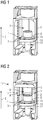
- a part of a housing 2 of a molded case circuit breaker is schematically shown in a perspective view.
- a fixation screw 4 is arranged in a cavity 7 of the housing 2.
- a shaft 12 of the fixation screw 4 is protruding through a screw hole 3 of a holding plate 14 of the housing 2.
- a washer 13 is sandwiched at the screw hole 12 between the holding plate 14 and a screw head 6 of the fixation screw 4. In this state, the fixation screw 4 is fully inserted in the screw hole 12.
- FIG. 2 the part of the housing 2 of the molded case circuit breaker of Fig. 1 is schematically shown in a perspective view, wherein an assembly device 1 is arranged within the cavity 7 above the screw head 6. Consequently, Fig. 2 shows a part of the circuit breaker system 11 according to the invention.
- the assembly device 1 comprises a screw head holding means 5 with a reception 8 for receiving and temporarily holding the screw head 6.
- the screw head 6 is insertable into the reception 8 in an engagement direction E that is parallel to a longitudinal axis of the fixation screw 4 through an opening 9. In this state, the screw head 6 is not engaged with the assembly device 1.
- FIG. 3 part of the circuit breaker system 11 of Fig. 2 is shown in a perspective view, wherein the fixation screw 4 is in a different position and is not fully inserted into the screw hole 3.
- the screw head 6 is fully arranged inside the reception 8 of the screw head holding means 5 and thus engaged with the screw head holding means 5.
- the washer 13 is still secured at the shaft 12 between the holding plate 14 and the screw head 6 because a part of the shaft 12 still protrudes through the screw hole 3.
- the fixation screw 4 is temporarily secured at the housing 2 of the circuit breaker system 11 against falling off unintentionally.
- Fig. 4 shows a part of a preferred embodiment of a circuit breaker system 11 according to the invention in a sectional side view.
- the assembly device 1 has a plurality of protrusions 15 that are inserted into respective clearances 16 of the housing 2.
- the protrusions 15 and clearances 16 are configured such that the assembly device 1 is linearly guided at the housing 2.
- the assembly device 1 could be secured at the housing 2 by not shown clicking means.
- the assembly device 1 further comprises a stop element 10 that is arranged at a side of the reception 8 that is opposite to the opening 9. By means of the stop element 10, the screw head 6 can only be moved in and out of the reception 8 of the side of the opening 9.
- the stop element 10 has a central bore 17 for allowing a tool, such as a screw driver or Allen key, to engage with a respective portion of the screw head 6 in order to fasten or unfasten the fixation screw 4.
- a tool such as a screw driver or Allen key
- the assembly device 1 can be removed from the housing 2.
- the screw head 6 can be moved inside the reception 8 through the opening 9 until the screw head 6 engages the stop element 10.
Landscapes
- Engineering & Computer Science (AREA)
- Manufacturing & Machinery (AREA)
- Power Engineering (AREA)
- Breakers (AREA)
Claims (9)
- Leistungsschaltersystem (11), das einen Kompaktleistungsschalter mit einem Gehäuse (2), zumindest einem Schraubenloch (3) zum Befestigen des Kompaktleistungsschalters mit einer Befestigungsschraube (4) an einer Stromschiene und mindestens einem Hohlraum (7) zum Aufnehmen einer Montagevorrichtung (1) zum Verbessern des Befestigens des Kompaktleistungsschalters an der Stromschiene umfasst,
wobei
die Montagevorrichtung (1) ein Schraubenkopfhaltemittel (5) zum Halten eines Schraubenkopfs (6) der Befestigungsschraube (4) umfasst, wobei die Montagevorrichtung (1) für ein derartiges Anordnen in einem Hohlraum (7) des Gehäuses (2) des Kompaktleistungsschalters ausgelegt ist, dass ein Schraubenkopf (6) der Befestigungsschraube (4), der zum Anbringen des Kompaktleistungsschalters an der Stromschiene an dem Schraubenloch (3) angeordnet ist, in Eingriffsrichtung (E) in das Schraubenkopfhaltemittel (5) eingreifen kann,
dadurch gekennzeichnet, dass
der Schraubenkopf (6) nicht in die Montagevorrichtung (1) eingreift, wenn die Befestigungsschraube (4) vollständig in das Schraubenloch (3) eingeführt ist. - Leistungsschaltersystem (11) nach Anspruch 1,
dadurch gekennzeichnet, dass
das Schraubenkopfhaltemittel (5) so ausgelegt ist, dass die Eingriffsrichtung (E) parallel zu einer Längsachse (L) der Befestigungsschraube (4) verläuft. - Leistungsschaltersystem (11) nach Anspruch 1 oder 2,
dadurch gekennzeichnet, dass
das Schraubenkopfhaltemittel (5) eine Innenaufnahme (8) aufweist, die zum Aufnehmen und Halten des Schraubenkopfs (6) ausgelegt ist. - Leistungsschaltersystem (11) nach Anspruch 3,
dadurch gekennzeichnet, dass
die Aufnahme (8) eine Öffnung (9) zum Aufnehmen des Schraubenkopfs (6) und zumindest ein Anschlagelement (10) aufweist, welches verhindert, dass der Schraubenkopf (6) in Eingriffsrichtung (E) durch die Aufnahme (8) hindurchgedrückt wird. - Leistungsschaltersystem (11) nach einem der vorhergehenden Ansprüche,
dadurch gekennzeichnet, dass
die Montagevorrichtung (1) drei gleichmäßig beabstandete Schraubenkopfhaltemittel (5) umfasst, die so angeordnet sind, dass sich die Montagevorrichtung (1) an dem Gehäuse (2) eines Kompaktleistungsschalters mit drei entsprechenden, gleichmäßig beabstandeten Schraubenlöchern (3) anbringen lässt, wobei sich jedes der drei Schraubenkopfhaltemittel (5) zum Aufnehmen eines Schraubenkopfs (6) einer durch das Schraubenloch (3) verlaufenden Befestigungsschraube (4) auf ein Schraubenloch (3) des Gehäuses (2) ausrichten lässt. - Leistungsschaltersystem (11) nach einem der vorhergehenden Ansprüche,
dadurch gekennzeichnet, dass
der Hohlraum (7) des Gehäuses (2) des Kompaktleistungsschalters die Form eines Kranzes aufweist, wobei sich die Montagevorrichtung (1) derart in dem Kranz anbringen lässt, dass sie lösbar an dem Leistungsschalter befestigt ist. - Verfahren zum Anbringen eines Kompaktleistungsschalters an einer Stromschiene, das folgende Schritte umfasst:- Bereitstellen eines Kompaktleistungsschaltersystems (11) nach einem der vorhergehenden Ansprüche,- Hindurchführen eines Schafts (12) einer Befestigungsschraube (4) durch ein Schraubenloch (3) eines Gehäuses (2) des Leistungsschalters,- derartiges Anordnen einer Montagevorrichtung (1) des Leistungsschaltersystems (11) an dem Gehäuse (2), dass ein Schraubenkopfhaltemittel (5) der Montagevorrichtung (5) auf einen Schraubenkopf (6) der Schraube (4) ausgerichtet ist,- Bewegen des Schraubenkopfs (6) in eine Aufnahme (8) des Schraubenkopfhaltemittels (5), bis er lösbar in dem Schraubenkopfhaltemittel (5) befestigt ist,- Anordnen des Kompaktleistungsschalters an einer Anbringstelle an der Stromschiene und- Befestigen der Befestigungsschraube (4) und dadurch des Kompaktleistungsschalters an der Stromschiene.
- Verfahren nach Anspruch 7,
dadurch gekennzeichnet, dass
die Montagevorrichtung (1) entfernt wird, wenn die Befestigungsschraube (4) teilweise oder vollständig mit einem mit Gewinde versehenen Abschnitt der Stromschiene in Eingriff steht. - Verfahren nach Anspruch 7 oder 8,
dadurch gekennzeichnet, dass
der Schraubenkopf (6) durch Drücken in die Aufnahme (8) bewegt wird.
Priority Applications (3)
| Application Number | Priority Date | Filing Date | Title |
|---|---|---|---|
| EP15185207.6A EP3144952B1 (de) | 2015-09-15 | 2015-09-15 | Montagevorrichtung, schutzschaltersystem und verfahren zur verbesserung der befestigung eines leistungsschalters mit gegossenem gehäuse an einer stromschiene |
| US15/183,898 US9978552B2 (en) | 2015-09-15 | 2016-06-16 | Assembly device, circuit breaker system and method for improving fixing a molded case circuit breaker to a bus bar |
| CN201610545829.9A CN106532525A (zh) | 2015-09-15 | 2016-07-12 | 装配设备、断路器系统和改善固定断路器到母线的方法 |
Applications Claiming Priority (1)
| Application Number | Priority Date | Filing Date | Title |
|---|---|---|---|
| EP15185207.6A EP3144952B1 (de) | 2015-09-15 | 2015-09-15 | Montagevorrichtung, schutzschaltersystem und verfahren zur verbesserung der befestigung eines leistungsschalters mit gegossenem gehäuse an einer stromschiene |
Publications (2)
| Publication Number | Publication Date |
|---|---|
| EP3144952A1 EP3144952A1 (de) | 2017-03-22 |
| EP3144952B1 true EP3144952B1 (de) | 2018-03-28 |
Family
ID=54147042
Family Applications (1)
| Application Number | Title | Priority Date | Filing Date |
|---|---|---|---|
| EP15185207.6A Not-in-force EP3144952B1 (de) | 2015-09-15 | 2015-09-15 | Montagevorrichtung, schutzschaltersystem und verfahren zur verbesserung der befestigung eines leistungsschalters mit gegossenem gehäuse an einer stromschiene |
Country Status (3)
| Country | Link |
|---|---|
| US (1) | US9978552B2 (de) |
| EP (1) | EP3144952B1 (de) |
| CN (1) | CN106532525A (de) |
Families Citing this family (1)
| Publication number | Priority date | Publication date | Assignee | Title |
|---|---|---|---|---|
| WO2019129520A1 (en) * | 2017-12-28 | 2019-07-04 | Datawalk Spolka Akcyjna | Systems and methods for combining data analyses |
Family Cites Families (11)
| Publication number | Priority date | Publication date | Assignee | Title |
|---|---|---|---|---|
| US4358815A (en) * | 1979-05-04 | 1982-11-09 | Eaton Corporation | Panelboard for bolt-in and plug-in circuit breakers |
| JPS60130068A (ja) * | 1983-12-15 | 1985-07-11 | 松下電工株式会社 | 端子装置 |
| DE8702835U1 (de) * | 1987-02-25 | 1988-03-24 | Licentia Patent-Verwaltungs-Gmbh, 6000 Frankfurt, De | |
| GB8802663D0 (en) * | 1988-02-05 | 1988-03-02 | Delta Electrical Holdings | Mounting assembly for electrical devices |
| DE9406404U1 (de) * | 1994-04-20 | 1994-06-23 | Kloeckner Moeller Gmbh | Elektrisches Schaltgerät mit Ausblaskanälen für Lichtbogengase |
| JP3156540B2 (ja) * | 1995-04-11 | 2001-04-16 | 富士電機株式会社 | 電気機器の端子装置 |
| DE102004017393B3 (de) * | 2004-04-08 | 2005-12-08 | Elektro-Bauelemente Gmbh | Befestigungselement für NH-Sicherungsleisten |
| CN202301369U (zh) * | 2011-11-10 | 2012-07-04 | 天佑电器(苏州)有限公司 | 系留螺钉 |
| PL224301B1 (pl) * | 2013-09-11 | 2016-12-30 | APATOR Spółka Akcyjna | Rozłącznik, zwłaszcza rozłącznik izolacyjny bezpiecznikowy z modułem szybkiego montażu |
| PL224552B1 (pl) * | 2013-09-11 | 2017-01-31 | APATOR Spółka Akcyjna | Obudowa modułu szybkiego montażu rozłącznika izolacyjnego bezpiecznikowego |
| WO2016057966A1 (en) * | 2014-10-09 | 2016-04-14 | Declark Daniel Dale | Flush mount screw anchor |
-
2015
- 2015-09-15 EP EP15185207.6A patent/EP3144952B1/de not_active Not-in-force
-
2016
- 2016-06-16 US US15/183,898 patent/US9978552B2/en active Active
- 2016-07-12 CN CN201610545829.9A patent/CN106532525A/zh active Pending
Non-Patent Citations (1)
| Title |
|---|
| None * |
Also Published As
| Publication number | Publication date |
|---|---|
| US20170076897A1 (en) | 2017-03-16 |
| CN106532525A (zh) | 2017-03-22 |
| US9978552B2 (en) | 2018-05-22 |
| EP3144952A1 (de) | 2017-03-22 |
Similar Documents
| Publication | Publication Date | Title |
|---|---|---|
| KR20060045066A (ko) | 전기기기의 단자 장치 | |
| US20190140388A1 (en) | Modular holding frame for plug connectors | |
| US10965110B2 (en) | Support apparatus usable with electrical enclosure | |
| CN102804320B (zh) | 用于电路断路器的改进的拴系配件 | |
| US7146833B2 (en) | Closing cylinder | |
| US10354812B1 (en) | Circuit breaker lockout device | |
| EP3144952B1 (de) | Montagevorrichtung, schutzschaltersystem und verfahren zur verbesserung der befestigung eines leistungsschalters mit gegossenem gehäuse an einer stromschiene | |
| US20080123256A1 (en) | Busbar assembly | |
| EP1187996A2 (de) | Anschlussklemme für schutzschalter | |
| US8454393B2 (en) | Device and method for the captive accommodation of a screw in a terminal | |
| US20020057551A1 (en) | Ready to wire terminal assembly with vibration resistant clamping screws | |
| EP2409098B1 (de) | Steuerkastenanordnung mit einem montageelement | |
| CA2706009A1 (en) | Mounting device with at least one captive mounting screw | |
| US6275126B1 (en) | Molded case power switch with secondary cover removably secured by quick release fasteners | |
| EP2716859B1 (de) | Rohrmotor mit Halterung für ein Befestigungselement | |
| US6208229B1 (en) | Moulded case power switch housing with removably secured secondary cover | |
| US4889299A (en) | Duct mounting fixture for securing a duct on a support section | |
| US20060251491A1 (en) | Fastener holder permitting centering between fastened components | |
| CN210068642U (zh) | 用于构件的固定件及具有它的组件 | |
| US10056215B1 (en) | Universal adjustable electrical circuit breaker locking device | |
| US6501021B1 (en) | Shimming device for electrical box | |
| US6281771B1 (en) | Molded case power switch with secondary cover removably secured by captured rotatable nut | |
| EP3207606B1 (de) | Wandbefestigtes elektrisches gehäuse | |
| US9829017B2 (en) | Mounting device for temporarily affixing an auxiliary device to a motor control center | |
| EP1806815A1 (de) | Ein Schaltschrankgehäuse |
Legal Events
| Date | Code | Title | Description |
|---|---|---|---|
| PUAI | Public reference made under article 153(3) epc to a published international application that has entered the european phase |
Free format text: ORIGINAL CODE: 0009012 |
|
| AK | Designated contracting states |
Kind code of ref document: A1 Designated state(s): AL AT BE BG CH CY CZ DE DK EE ES FI FR GB GR HR HU IE IS IT LI LT LU LV MC MK MT NL NO PL PT RO RS SE SI SK SM TR |
|
| AX | Request for extension of the european patent |
Extension state: BA ME |
|
| RAP1 | Party data changed (applicant data changed or rights of an application transferred) |
Owner name: SIEMENS AKTIENGESELLSCHAFT |
|
| 17P | Request for examination filed |
Effective date: 20170919 |
|
| RBV | Designated contracting states (corrected) |
Designated state(s): AL AT BE BG CH CY CZ DE DK EE ES FI FR GB GR HR HU IE IS IT LI LT LU LV MC MK MT NL NO PL PT RO RS SE SI SK SM TR |
|
| GRAP | Despatch of communication of intention to grant a patent |
Free format text: ORIGINAL CODE: EPIDOSNIGR1 |
|
| RIC1 | Information provided on ipc code assigned before grant |
Ipc: H01H 71/08 20060101AFI20171026BHEP Ipc: H02B 1/052 20060101ALI20171026BHEP |
|
| INTG | Intention to grant announced |
Effective date: 20171122 |
|
| GRAS | Grant fee paid |
Free format text: ORIGINAL CODE: EPIDOSNIGR3 |
|
| GRAA | (expected) grant |
Free format text: ORIGINAL CODE: 0009210 |
|
| AK | Designated contracting states |
Kind code of ref document: B1 Designated state(s): AL AT BE BG CH CY CZ DE DK EE ES FI FR GB GR HR HU IE IS IT LI LT LU LV MC MK MT NL NO PL PT RO RS SE SI SK SM TR |
|
| REG | Reference to a national code |
Ref country code: GB Ref legal event code: FG4D |
|
| REG | Reference to a national code |
Ref country code: CH Ref legal event code: EP |
|
| REG | Reference to a national code |
Ref country code: AT Ref legal event code: REF Ref document number: 984114 Country of ref document: AT Kind code of ref document: T Effective date: 20180415 |
|
| REG | Reference to a national code |
Ref country code: IE Ref legal event code: FG4D |
|
| REG | Reference to a national code |
Ref country code: DE Ref legal event code: R096 Ref document number: 602015009269 Country of ref document: DE |
|
| PG25 | Lapsed in a contracting state [announced via postgrant information from national office to epo] |
Ref country code: LT Free format text: LAPSE BECAUSE OF FAILURE TO SUBMIT A TRANSLATION OF THE DESCRIPTION OR TO PAY THE FEE WITHIN THE PRESCRIBED TIME-LIMIT Effective date: 20180328 Ref country code: NO Free format text: LAPSE BECAUSE OF FAILURE TO SUBMIT A TRANSLATION OF THE DESCRIPTION OR TO PAY THE FEE WITHIN THE PRESCRIBED TIME-LIMIT Effective date: 20180628 Ref country code: FI Free format text: LAPSE BECAUSE OF FAILURE TO SUBMIT A TRANSLATION OF THE DESCRIPTION OR TO PAY THE FEE WITHIN THE PRESCRIBED TIME-LIMIT Effective date: 20180328 Ref country code: HR Free format text: LAPSE BECAUSE OF FAILURE TO SUBMIT A TRANSLATION OF THE DESCRIPTION OR TO PAY THE FEE WITHIN THE PRESCRIBED TIME-LIMIT Effective date: 20180328 |
|
| REG | Reference to a national code |
Ref country code: NL Ref legal event code: MP Effective date: 20180328 |
|
| REG | Reference to a national code |
Ref country code: LT Ref legal event code: MG4D |
|
| PG25 | Lapsed in a contracting state [announced via postgrant information from national office to epo] |
Ref country code: RS Free format text: LAPSE BECAUSE OF FAILURE TO SUBMIT A TRANSLATION OF THE DESCRIPTION OR TO PAY THE FEE WITHIN THE PRESCRIBED TIME-LIMIT Effective date: 20180328 Ref country code: LV Free format text: LAPSE BECAUSE OF FAILURE TO SUBMIT A TRANSLATION OF THE DESCRIPTION OR TO PAY THE FEE WITHIN THE PRESCRIBED TIME-LIMIT Effective date: 20180328 Ref country code: SE Free format text: LAPSE BECAUSE OF FAILURE TO SUBMIT A TRANSLATION OF THE DESCRIPTION OR TO PAY THE FEE WITHIN THE PRESCRIBED TIME-LIMIT Effective date: 20180328 Ref country code: GR Free format text: LAPSE BECAUSE OF FAILURE TO SUBMIT A TRANSLATION OF THE DESCRIPTION OR TO PAY THE FEE WITHIN THE PRESCRIBED TIME-LIMIT Effective date: 20180629 Ref country code: BG Free format text: LAPSE BECAUSE OF FAILURE TO SUBMIT A TRANSLATION OF THE DESCRIPTION OR TO PAY THE FEE WITHIN THE PRESCRIBED TIME-LIMIT Effective date: 20180628 |
|
| PG25 | Lapsed in a contracting state [announced via postgrant information from national office to epo] |
Ref country code: ES Free format text: LAPSE BECAUSE OF FAILURE TO SUBMIT A TRANSLATION OF THE DESCRIPTION OR TO PAY THE FEE WITHIN THE PRESCRIBED TIME-LIMIT Effective date: 20180328 Ref country code: AL Free format text: LAPSE BECAUSE OF FAILURE TO SUBMIT A TRANSLATION OF THE DESCRIPTION OR TO PAY THE FEE WITHIN THE PRESCRIBED TIME-LIMIT Effective date: 20180328 Ref country code: IT Free format text: LAPSE BECAUSE OF FAILURE TO SUBMIT A TRANSLATION OF THE DESCRIPTION OR TO PAY THE FEE WITHIN THE PRESCRIBED TIME-LIMIT Effective date: 20180328 Ref country code: EE Free format text: LAPSE BECAUSE OF FAILURE TO SUBMIT A TRANSLATION OF THE DESCRIPTION OR TO PAY THE FEE WITHIN THE PRESCRIBED TIME-LIMIT Effective date: 20180328 Ref country code: PL Free format text: LAPSE BECAUSE OF FAILURE TO SUBMIT A TRANSLATION OF THE DESCRIPTION OR TO PAY THE FEE WITHIN THE PRESCRIBED TIME-LIMIT Effective date: 20180328 Ref country code: RO Free format text: LAPSE BECAUSE OF FAILURE TO SUBMIT A TRANSLATION OF THE DESCRIPTION OR TO PAY THE FEE WITHIN THE PRESCRIBED TIME-LIMIT Effective date: 20180328 Ref country code: NL Free format text: LAPSE BECAUSE OF FAILURE TO SUBMIT A TRANSLATION OF THE DESCRIPTION OR TO PAY THE FEE WITHIN THE PRESCRIBED TIME-LIMIT Effective date: 20180328 |
|
| PG25 | Lapsed in a contracting state [announced via postgrant information from national office to epo] |
Ref country code: SK Free format text: LAPSE BECAUSE OF FAILURE TO SUBMIT A TRANSLATION OF THE DESCRIPTION OR TO PAY THE FEE WITHIN THE PRESCRIBED TIME-LIMIT Effective date: 20180328 Ref country code: SM Free format text: LAPSE BECAUSE OF FAILURE TO SUBMIT A TRANSLATION OF THE DESCRIPTION OR TO PAY THE FEE WITHIN THE PRESCRIBED TIME-LIMIT Effective date: 20180328 Ref country code: CZ Free format text: LAPSE BECAUSE OF FAILURE TO SUBMIT A TRANSLATION OF THE DESCRIPTION OR TO PAY THE FEE WITHIN THE PRESCRIBED TIME-LIMIT Effective date: 20180328 |
|
| REG | Reference to a national code |
Ref country code: AT Ref legal event code: MK05 Ref document number: 984114 Country of ref document: AT Kind code of ref document: T Effective date: 20180328 |
|
| PG25 | Lapsed in a contracting state [announced via postgrant information from national office to epo] |
Ref country code: PT Free format text: LAPSE BECAUSE OF FAILURE TO SUBMIT A TRANSLATION OF THE DESCRIPTION OR TO PAY THE FEE WITHIN THE PRESCRIBED TIME-LIMIT Effective date: 20180730 |
|
| REG | Reference to a national code |
Ref country code: DE Ref legal event code: R097 Ref document number: 602015009269 Country of ref document: DE |
|
| PG25 | Lapsed in a contracting state [announced via postgrant information from national office to epo] |
Ref country code: AT Free format text: LAPSE BECAUSE OF FAILURE TO SUBMIT A TRANSLATION OF THE DESCRIPTION OR TO PAY THE FEE WITHIN THE PRESCRIBED TIME-LIMIT Effective date: 20180328 Ref country code: DK Free format text: LAPSE BECAUSE OF FAILURE TO SUBMIT A TRANSLATION OF THE DESCRIPTION OR TO PAY THE FEE WITHIN THE PRESCRIBED TIME-LIMIT Effective date: 20180328 |
|
| PLBE | No opposition filed within time limit |
Free format text: ORIGINAL CODE: 0009261 |
|
| STAA | Information on the status of an ep patent application or granted ep patent |
Free format text: STATUS: NO OPPOSITION FILED WITHIN TIME LIMIT |
|
| 26N | No opposition filed |
Effective date: 20190103 |
|
| REG | Reference to a national code |
Ref country code: DE Ref legal event code: R119 Ref document number: 602015009269 Country of ref document: DE |
|
| PG25 | Lapsed in a contracting state [announced via postgrant information from national office to epo] |
Ref country code: MC Free format text: LAPSE BECAUSE OF FAILURE TO SUBMIT A TRANSLATION OF THE DESCRIPTION OR TO PAY THE FEE WITHIN THE PRESCRIBED TIME-LIMIT Effective date: 20180328 |
|
| REG | Reference to a national code |
Ref country code: CH Ref legal event code: PL |
|
| PG25 | Lapsed in a contracting state [announced via postgrant information from national office to epo] |
Ref country code: SI Free format text: LAPSE BECAUSE OF FAILURE TO SUBMIT A TRANSLATION OF THE DESCRIPTION OR TO PAY THE FEE WITHIN THE PRESCRIBED TIME-LIMIT Effective date: 20180328 |
|
| REG | Reference to a national code |
Ref country code: BE Ref legal event code: MM Effective date: 20180930 |
|
| REG | Reference to a national code |
Ref country code: IE Ref legal event code: MM4A |
|
| PG25 | Lapsed in a contracting state [announced via postgrant information from national office to epo] |
Ref country code: LU Free format text: LAPSE BECAUSE OF NON-PAYMENT OF DUE FEES Effective date: 20180915 |
|
| PG25 | Lapsed in a contracting state [announced via postgrant information from national office to epo] |
Ref country code: IE Free format text: LAPSE BECAUSE OF NON-PAYMENT OF DUE FEES Effective date: 20180915 Ref country code: DE Free format text: LAPSE BECAUSE OF NON-PAYMENT OF DUE FEES Effective date: 20190402 |
|
| PG25 | Lapsed in a contracting state [announced via postgrant information from national office to epo] |
Ref country code: FR Free format text: LAPSE BECAUSE OF NON-PAYMENT OF DUE FEES Effective date: 20180930 Ref country code: BE Free format text: LAPSE BECAUSE OF NON-PAYMENT OF DUE FEES Effective date: 20180930 Ref country code: LI Free format text: LAPSE BECAUSE OF NON-PAYMENT OF DUE FEES Effective date: 20180930 Ref country code: CH Free format text: LAPSE BECAUSE OF NON-PAYMENT OF DUE FEES Effective date: 20180930 |
|
| PG25 | Lapsed in a contracting state [announced via postgrant information from national office to epo] |
Ref country code: MT Free format text: LAPSE BECAUSE OF NON-PAYMENT OF DUE FEES Effective date: 20180915 |
|
| PG25 | Lapsed in a contracting state [announced via postgrant information from national office to epo] |
Ref country code: TR Free format text: LAPSE BECAUSE OF FAILURE TO SUBMIT A TRANSLATION OF THE DESCRIPTION OR TO PAY THE FEE WITHIN THE PRESCRIBED TIME-LIMIT Effective date: 20180328 |
|
| PG25 | Lapsed in a contracting state [announced via postgrant information from national office to epo] |
Ref country code: CY Free format text: LAPSE BECAUSE OF FAILURE TO SUBMIT A TRANSLATION OF THE DESCRIPTION OR TO PAY THE FEE WITHIN THE PRESCRIBED TIME-LIMIT Effective date: 20180328 Ref country code: HU Free format text: LAPSE BECAUSE OF FAILURE TO SUBMIT A TRANSLATION OF THE DESCRIPTION OR TO PAY THE FEE WITHIN THE PRESCRIBED TIME-LIMIT; INVALID AB INITIO Effective date: 20150915 Ref country code: MK Free format text: LAPSE BECAUSE OF NON-PAYMENT OF DUE FEES Effective date: 20180328 |
|
| PG25 | Lapsed in a contracting state [announced via postgrant information from national office to epo] |
Ref country code: IS Free format text: LAPSE BECAUSE OF FAILURE TO SUBMIT A TRANSLATION OF THE DESCRIPTION OR TO PAY THE FEE WITHIN THE PRESCRIBED TIME-LIMIT Effective date: 20180728 |
|
| PGFP | Annual fee paid to national office [announced via postgrant information from national office to epo] |
Ref country code: GB Payment date: 20201002 Year of fee payment: 6 |
|
| GBPC | Gb: european patent ceased through non-payment of renewal fee |
Effective date: 20210915 |
|
| PG25 | Lapsed in a contracting state [announced via postgrant information from national office to epo] |
Ref country code: GB Free format text: LAPSE BECAUSE OF NON-PAYMENT OF DUE FEES Effective date: 20210915 |