EP3144778A1 - Bilayer haptic feedback actuator - Google Patents
Bilayer haptic feedback actuator Download PDFInfo
- Publication number
- EP3144778A1 EP3144778A1 EP16185272.8A EP16185272A EP3144778A1 EP 3144778 A1 EP3144778 A1 EP 3144778A1 EP 16185272 A EP16185272 A EP 16185272A EP 3144778 A1 EP3144778 A1 EP 3144778A1
- Authority
- EP
- European Patent Office
- Prior art keywords
- haptic feedback
- material strip
- bilayer material
- user
- thermal energy
- Prior art date
- Legal status (The legal status is an assumption and is not a legal conclusion. Google has not performed a legal analysis and makes no representation as to the accuracy of the status listed.)
- Withdrawn
Links
Images


Classifications
-
- G—PHYSICS
- G06—COMPUTING OR CALCULATING; COUNTING
- G06F—ELECTRIC DIGITAL DATA PROCESSING
- G06F3/00—Input arrangements for transferring data to be processed into a form capable of being handled by the computer; Output arrangements for transferring data from processing unit to output unit, e.g. interface arrangements
- G06F3/01—Input arrangements or combined input and output arrangements for interaction between user and computer
- G06F3/016—Input arrangements with force or tactile feedback as computer generated output to the user
-
- H—ELECTRICITY
- H02—GENERATION; CONVERSION OR DISTRIBUTION OF ELECTRIC POWER
- H02N—ELECTRIC MACHINES NOT OTHERWISE PROVIDED FOR
- H02N2/00—Electric machines in general using piezoelectric effect, electrostriction or magnetostriction
- H02N2/02—Electric machines in general using piezoelectric effect, electrostriction or magnetostriction producing linear motion, e.g. actuators; Linear positioners ; Linear motors
- H02N2/04—Constructional details
-
- H—ELECTRICITY
- H10—SEMICONDUCTOR DEVICES; ELECTRIC SOLID-STATE DEVICES NOT OTHERWISE PROVIDED FOR
- H10N—ELECTRIC SOLID-STATE DEVICES NOT OTHERWISE PROVIDED FOR
- H10N30/00—Piezoelectric or electrostrictive devices
- H10N30/20—Piezoelectric or electrostrictive devices with electrical input and mechanical output, e.g. functioning as actuators or vibrators
-
- H—ELECTRICITY
- H10—SEMICONDUCTOR DEVICES; ELECTRIC SOLID-STATE DEVICES NOT OTHERWISE PROVIDED FOR
- H10N—ELECTRIC SOLID-STATE DEVICES NOT OTHERWISE PROVIDED FOR
- H10N30/00—Piezoelectric or electrostrictive devices
- H10N30/80—Constructional details
- H10N30/85—Piezoelectric or electrostrictive active materials
-
- H—ELECTRICITY
- H01—ELECTRIC ELEMENTS
- H01H—ELECTRIC SWITCHES; RELAYS; SELECTORS; EMERGENCY PROTECTIVE DEVICES
- H01H2215/00—Tactile feedback
-
- Y—GENERAL TAGGING OF NEW TECHNOLOGICAL DEVELOPMENTS; GENERAL TAGGING OF CROSS-SECTIONAL TECHNOLOGIES SPANNING OVER SEVERAL SECTIONS OF THE IPC; TECHNICAL SUBJECTS COVERED BY FORMER USPC CROSS-REFERENCE ART COLLECTIONS [XRACs] AND DIGESTS
- Y10—TECHNICAL SUBJECTS COVERED BY FORMER USPC
- Y10S—TECHNICAL SUBJECTS COVERED BY FORMER USPC CROSS-REFERENCE ART COLLECTIONS [XRACs] AND DIGESTS
- Y10S310/00—Electrical generator or motor structure
- Y10S310/80—Piezoelectric polymers, e.g. PVDF
Definitions
- the present application relates generally to haptic feedback actuators and their construction and use in touch based systems.
- the haptic feedback actuators are suitably bilayer structures including at least two materials having different thermal coefficients, allowing the structure to deflect from a first position to a second position in response to heating and/or cooling of the structure.
- Haptic effects are used to enhance the interaction of an individual with an electronic device. Haptic effects enable the user to experience a touch sensation, which is typically generated by an actuator embedded in the device. Such a haptic effect actuator provides acknowledgement or feedback of a user's interaction with the electronic device, alternatively, or in addition to, visual and/or audio effects via a display or audio device. There continues to be a need for providing such feedback via non-visible user interfaces in a wide variety of sizes of devices. The size and power consumption of such haptic effect actuators become more important as an increasing number of electronic devices with user interfaces require efficient power consumption. There remains a need in the art for haptic effect actuators that have a low profile, such as by being thin or compact, and that consume less power.
- haptic feedback generator a device having a haptic feedback generator.
- the systems suitably include a device having a haptic feedback generator, wherein the haptic feedback generator includes a bilayer material strip.
- the bilayer material strip in response to a change in temperature, is configured to deflect between a first position and a second position to provide haptic feedback to the user.
- the methods include increasing the temperature of a first thermal energy source/sink in the haptic feedback generator system, thereby increasing the temperature of a bilayer material strip in the system, and deflecting the bilayer material strip between a first position and a second position to generate haptic feedback to the user.
- a system 100 suitably includes a device 104 having a haptic feedback generator 106A, which in embodiments, is also described herein as a user touchable haptic signal generator.
- haptic feedback refers to information such as vibration, texture, and/or heat, etc., that are transferred, via the sense of touch, from a system as described herein to a user. Haptic feedback can also be described as a haptic feedback signal in embodiments herein.
- Examples of device 104 which can include haptic feedback generator 106A include various wearables, mobile phones and tablets, touchpads, keyboards, gaming consoles and controllers, etc.
- a user 102 interacts with device 104.
- haptic feedback generator 106A deforms or deflects to deflected haptic feedback generator 106B (also described as deflected haptic signal generator in embodiments herein) by rising toward user 102 to thereby create haptic feedback 108 (e.g., pressure, touch or vibration) from haptic feedback generator 106A.
- user interaction suitably includes touching the surface of device 104, e.g., a substrate 110 of device 104 (such as a touchpad surface, touch screen, glass or plastic cover, etc.)
- the interaction can include directly touching haptic feedback generator 106A.
- the user interaction can also comprise the user coming sufficiently close enough to the haptic feedback generator to initiate the deflection without actually touching the haptic feedback generator.
- haptic feedback generator 106A includes a bilayer material strip 202 (see FIGS. 2A-2B ) for generating or providing a haptic feedback force that may be felt by a user.
- the generated haptic feedback provided by actuation of the bilayer material strip is of a sufficient force so as to not be inhibited or blocked by a user's normal contact pressure that the user may apply against a touch surface or touchable user interface, including haptic feedback generator 106A and substrate 110. That is, the haptic feedback force is sufficiently strong such that user 102 will be able to feel the deflection of bilayer material strip 202 upward against the touch of the user.
- Methods for increasing the haptic feedback force are described herein and include the use of adding materials, such as further layers or additional mass, to bilayer material strip 202 to increase its thickness or overall weight.
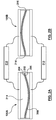
- FIGS. 2A and 2B are sectional views of exemplary haptic feedback generator 106A and deflected haptic feedback generator 106B, which are housed within or supported by device 104.
- haptic feedback generator 106A is a touchable feedback generator, though direct touching is not required to initiate the haptic feedback as described herein.
- Haptic feedback generator 106A suitably includes bilayer material strip 202 coupled to a substrate 110 or device 104, for example, at opposing ends 214 and 216 of the bilayer material strip 202, as shown in FIG. 2B .
- bilayer material strip 202 can be attached at opposing ends 214 and 216 using, for example, various adhesives or glues, rubber attachment points, or mechanical pivots, hinges, or other connection elements that allow the bilayer material strip to pivot or deflect between the first position and the second position, including allowing for oscillation and vibration, without becoming detached from haptic feedback generator 106A.
- a process is initiated which causes bilayer material strip 202 to deflect from a first position ( FIG. 2A ), in which the bilayer material strip has a substantially concave profile, protruding away from the user, to a second position ( FIG. 2B ), in which the bilayer material strip has a substantially convex profile, protruding toward the user, to provide the haptic feedback 108 to user 102.
- Haptic feedback 108 confirms the user contact (or sufficiently close interaction) with haptic feedback generator 106A.
- the haptic feedback generator 106A deflects (i.e., deforms or "snaps") to deflected haptic feedback generator 106B.
- bilayer material strip 202 includes a first layer 204 and a second layer 206.
- First layer 204 and second layer 206 are suitably two strip-shaped (or layered) materials which are associated, bonded or otherwise adhered to one another all along a common boundary 208 between first layer 204 and second layer 206.
- Strip-shaped denotes that first layer 204 and second layer 206, and thus bilayer material strip 202, has a structure in which the length of the structure is longer than it is wide, and that has a thickness that is smaller than its width.
- bilayer material strip 202 can include multiple layers which result in a structure displaying substantially similar mechanical characteristics of bilayer material strip 202, in that a multi-layer structure deflects from the first position to the second position in response to a change in temperature, as described herein.
- a multi-layer structure can include three, four, five, six, seven, eight, nine, ten, etc., layers, to ultimately form bilayer material strip 202.
- a multi-layer structure can be bound or adhered together to result in a structure similar to that of bilayer material strip 202, with essentially two distinct sections (each of which is made up of multiple layers) of the strip that have different material properties, as described herein.
- first layer 204 includes a first material
- second layer 206 includes a second material that is different from the first material.
- the first and second materials are metallic materials as described herein, resulting in a bimetal strip.
- the first material and the second material may be selected so as to have different coefficients of thermal expansion (CTE).
- CTE coefficients of thermal expansion
- the first material of first layer 204 in embodiments can have a higher CTE than the second material of second layer 206.
- the first material may be copper and the second material may be iron.
- Exemplary materials and structures for use in bilayer material strip 202, including bimetals, are described for example in S. Boisseau, et al., Semi-flexible Bimetal-based Thermal Energy Harvesters, Smart Mater. Struct. 22 (2013) 025021 (8pp ), the disclosure of which is hereby incorporated by reference herein in its entirety.
- first layer 204 can have a higher CTE than second layer 206. Upon heating, first layer 204 expands more rapidly than second layer 206, causing a stress, which can be a torque or other force, to be generated in the bilayer material 202 which subsequently causes bilayer material 202 to deflect from the first position to the second position in a "snapping" motion.
- the layers which make up bilayer material strip 202 are bonded together and processed in a way that establishes a particular pre-set, shape set, or shape memory configuration for bilayer material strip 202.
- the materials can be processed to be formed into a curved shape (i.e., the convex shape of FIG.
- the materials can be processed to be formed, such as by being stamped, into a V-shape, providing the initial or shape set/memory configuration of the bilayer material strip, prior to the changes in temperature that are described herein.
- setting in the curved shape or a V-shape configuration may be accomplished via stamping (e.g., using a mechanical die or stamp to form a bilayer material strip into a curve or a V-shape).
- bilayer material strip 202 By heating bilayer material strip 202, the material layers (2 or more as described herein) increase in temperature.
- the different coefficients of thermal expansion (CTE) of the different materials in bilayer material strip 202 cause differential forces between the two layers of the bilayer material strip 202 to increase.
- CTE coefficients of thermal expansion
- coupling moments occur at the fixed ends of bilayer material strip 202 (i.e., 214 and 216 in FIG. 2B ).
- the high lateral forces result from the different rates of thermal expansion due to the differences in the coefficients of thermal expansion of the materials which make up the strip.
- the magnitude of the couples overcome the curvature in the bilayer material strip, causing it to snap or deform.
- bilayer material strip 202 can deform or deflect from the first position in FIG. 2A to the second position in FIG. 2B upon heating, and then deform or deflect back to the first position of FIG. 2A upon cooling.
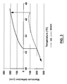
- FIG. 3 shows a hysteresis cycle for an exemplary bilayer material strip 202 (suitably a bimetallic strip) for use in embodiments described herein.
- FIG. 3 illustrates the deflection over a temperature range of about 42°C to about 48°C, showing maximum deflection in microns.
- FIG. 3 demonstrates that as the temperature of the bilayer material strip rises (dotted line in FIG. 3 ), the strip reaches a "snap activation temperature" (about 47 °C in FIG. 3 ), where the strip undergoes a rapid deflection without a further detectable temperature rise.
- the bilayer material strip 202 deflects or "snaps" from a lower thermal energy source/sink, i.e., lower or bottom hot source, to be in contact with an upper thermal energy source/sink, i.e., upper or top cold source, as described below.
- a lower thermal energy source/sink i.e., lower or bottom hot source
- an upper thermal energy source/sink i.e., upper or top cold source
- the temperature of the bilayer material strip decreases until it reaches an inflection temperature of approximately 42.5 °C (see solid line in FIG. 3 ).
- the material deflects or snaps from being in contact with the upper cold source, to being again in contact with the lower hot source.
- a displacement of bilayer material strip 202 that results from its deflection will be on the order of 100's of microns to several millimeters. This displacement or deflection is measured from an initial position of the strip (e.g., the concave configuration of FIG. 2A ) to a deflected position of the strip (e.g., the convex configuration, toward the user, in FIG. 2B ).
- the displacement of the bilayer material strip caused by the deflection is about 0.1 mm to about 5 mm, about 0.1 mm to about 2 mm, about 0.1 mm to about 1 mm, or about 0.1-0.5 mm, so as to provide various haptic feedback effects to a user.
- Such a displacement may take place only a single time for each interaction by a user, i.e., a single deflection or deformation for each time the user interacts with the system, or may take place several or a plurality of times for each interaction by a user.
- the displacement can be on the order of 10's of microns to 100's of microns, but occurring with a frequency of more than once per user interaction, i.e., multiple or a plurality of deflections or deformations each time the user interacts with the system, resulting in an oscillation or vibration.
- the frequency of oscillation of bilayer material strip 202 can be on the order of 1 Hz to about 1000 Hz, and suitably about 1 Hz to about 100 Hz, or the order of 10-100 Hz, 10-50 Hz, or about 10-20 Hz.
- bilayer material strip 202 is suitably of minimal thickness so as to maintain structural integrity while also allowing for haptic feedback.
- the use of a thin bilayer material strip allows for rapid heating and cooling, and thus rapid deflection or snapping.
- a thickness of bilayer material strip 202 is on the order of about 1 ⁇ m to about 1 mm, about 1 ⁇ m to about 500 ⁇ m, more suitably about 1 ⁇ m to about 400 ⁇ m, about 1 ⁇ m to about 300 ⁇ m, about 10 ⁇ m to about 300 ⁇ m, about 50 ⁇ m to about 300 ⁇ m, about 50 ⁇ m to about 200 ⁇ m, about 50 ⁇ m to about 150 ⁇ m, about 50 ⁇ m to about 100 ⁇ m, about 20 ⁇ m, about 30 ⁇ m, about 40 ⁇ m, about 50 ⁇ m, about 60 ⁇ m, about 70 ⁇ m, about 80 ⁇ m, about 90 ⁇ m, about 100 ⁇ m, about 110 ⁇ m, about 120 ⁇ m, about 130 ⁇ m, about 140 ⁇ m, about 150 ⁇ m, about 160 ⁇ m, about 170 ⁇ m, about 180 ⁇ m, about 190 ⁇ m, or about 200 ⁇
- bilayer material strip 202 is not limited to only rectangular or regular-shaped elements, but can have any geometry desired by the application or user, including various disk-shapes, circular-shapes, oblong-shapes, irregular-shapes, or other suitable geometries.
- the dimensions (i.e., length, width, diameter, circumference, etc.) of bilayer material strip 202 can also be dependent upon the final application, but will generally be on the order of millimeters to centimeters to 10's of centimeters.
- the process, impetus or change of condition/circumstance, that causes bilayer material strip 202 to deflect from the first position ( FIG. 2A ) to the second position ( FIG. 2B ) to provide haptic feedback 108 to user 102 (and thus confirming contact or near contact) is a change in temperature or also described herein as a thermal process.
- a "thermal process” refers to a process whereby heat is transferred to and/or from bilayer material strip 202, resulting in a change in temperature of the bilayer material strip and a deflection of the strip.
- bilayer material strip 202 is in a convex configuration (i.e., curved away from user 102) and toward a thermal energy source/sink 212.
- first layer 204 of the strip has a higher CTE and is disposed above second layer 206 having a lower CTE.
- bilayer material strip 202 is in a first position (or a downward state) and bilayer material strip 202 can be in contact with thermal energy source/sink 212.
- the first position shown in FIG. 2A is suitably a shape set or shape memory curved or V-shaped configuration of the strip.
- a change in temperature occurs as the result of a transfer of thermal energy from user 102 to a first thermal energy source/sink 212, caused by the user's contact, or sufficiently close interaction, with haptic feedback generator 106A or substrate 110 or other portion of device 104.
- haptic feedback generator 106A can comprise two thermal energy sources/sinks 210, 212 as shown, for instance, in FIGS. 2A and 2B . Additional thermal energy sources/sinks can also be utilized. Transfer of thermal energy from user 102 to, for example, thermal energy source/sink 212, increases the temperature of the thermal energy source/sink 212, which in turn increases the temperature of bilayer material strip 202, as described herein.
- Heat transfer between user 102 and thermal energy source/sink 212 can occur by a user's contact with thermal energy source/sink 210 (or other portion of device 104 including substrate 110), which can then transfer heat to thermal energy source/sink 212.
- the increase in temperature of bilayer material strip 202 results from the direct physical interaction (including conduction via contact) between bilayer material strip 202 and thermal energy source/sink 212. As described herein, the increase in temperature causes the bilayer material strip 202 to deflect from a first position ( FIG. 2A ) to a second position ( FIG. 2B ), as a result of the higher CTE material (layer 204) heating more rapidly than layer 206, which results in a force effect, thermal stress, thermal bowing, or torque in the material, and a deflection from the first position to the second position.
- the increase in temperature can also result from heat from thermal energy source/sink 210 transferring to bilayer material strip 202, simply by heating of surrounding air (e/g. convection) or other elements of the haptic feedback generator 106A.
- heating of thermal energy source/sink 210 caused by user 102 contact can transfer heat to thermal energy source/sink 212 by conduction (from one thermal energy source/sink to the other), thereby ultimately providing thermal energy source/sink 212 with sufficient heat to increase the temperature of bilayer material strip 202, and cause the deflection.
- thermal energy source/sink refers to a material that is able to absorb and transfer heat, either as a source of heat (conducting heat to another material), or as a sink for heat (removing or dissipating heat from another material).
- the thermal energy sources/sinks for use in the systems described herein can act as both a source and a sink, depending on the configuration and design of the systems.
- deflection of bilayer material strip 202 to its second position as shown in FIG. 2B causes a surface of the deflected haptic feedback generator 106B to contact the user, or be directed toward the user, such as shown in FIG. 1B .
- deflected haptic feedback generator 106B may bow to protrude above or beyond the surface of device 100.
- deflected haptic feedback generator can move substrate 110, which can be a touchpad surface, a touch screen, or a glass or plastic cover, etc., toward user 102.
- the change in temperature can further comprise a decrease in temperature of the bilayer material strip.
- This change in temperature can occur due to a transfer of thermal energy from bilayer material strip 202 to a thermal energy source/sink (e.g., 210), as a result of removal of the user's 102 contact with the deflected haptic feedback generator 106B. That is, when user 102 removes the contact from the deflected haptic feedback generator 106B, thermal energy source/sink 210 cools via passive diffusion of heat from thermal energy source/sink 210, allowing thermal energy from bilayer material strip 202 to transfer to thermal energy source/sink 210, which in turn decreases the temperature, or cools, bilayer material strip 202.
- this cooling can be rapid enough such that the temperature reduction of the bilayer material strip 202 causes the bilayer material strip 202 to deflect from the second position ( FIG. 2B ) back to the first position ( FIG. 2A ), or stated another way causes the bilayer material strip 202 to return or relax to its shape set or shape memory first position ( FIG. 2A ) from the second position ( FIG. 2B ).
- This process of heating, deflection, cooling, and return deflection can be repeated as often as desired or required by a particular application.
- Such embodiments which rely on the use of thermal energy from a user to heat (and ultimately cool) thermal sources/sinks are termed "passive" thermal processes or "passive" changes in temperature herein.
- bilayer material strip 202 can transfer thermal energy to an actively cooled thermal energy source/sink (e.g., 210), wherein the thermal energy source/sink (e.g., 210) may provide active cooling when triggered by, or in response to, the removal (or cessation) of a user's contact with the haptic feedback generator.
- the thermal energy source/sink e.g., 210
- the temperature of the bilayer material strip 202 decreases, causing the strip to deflect from the second position back to the first position.
- bilayer material strip 202 begins in a first position in FIG. 2A .
- bilayer material strip 202 deflects to a second position, as shown in FIG. 2B .
- the haptic feedback generator now deflected haptic feedback generator 106B
- Thermal energy can then transfer from bilayer material strip 202 to thermal energy source/sink 210, resulting in a decrease in the temperature of the strip.
- This thermal energy transfer causes the strip to deflect back to the first position, as the higher CTE of the upper or first layer 204 results in a faster cooling, and allows for the return to the initial curved configuration of bilayer material strip 202 in FIG. 2A .
- this process of heating, deflection, cooling, and return deflection can be repeated as often as desired by a particular application.
- thermal energy sources/sinks can comprise fluid channels which allow circulation of fluids to aid in cooling (heat dissipation) of thermal energy sinks, and can also be used to provide thermal energy sources (heating) in other embodiments.
- the fluid channels may provide one or more passages for a liquid cooling media, or cooling liquid, to pass through, wherein the liquid cooling media is circulated through a heat exchanger thermally isolated from the haptic feedback generator.
- a dual piezoelectric cooler can also be used to aid in cooling of the thermal energy sources/sinks.
- Such piezoelectric coolers generally rely on a bellowing action to emit pulses of air across a heat source. The action is driven by a piezoelectric actuator with the device to push air out and create a turbulent flow that entrains ambient air to create a jet-like stream and increase heat transfer. See for example, AAVID Thermalloy's "Dual Cool Jets," low profile air movers (San Jose, CA).
- thermal sources/sinks are termed "active" thermal processes herein, and utilize one or more heating elements or sources, and/or cooling mechanisms, to change the temperature of a thermal energy source/sink and thus change the temperature of bilayer material strip 202.
- an increase in temperature of the bilayer material strip can be triggered when user 102 makes contact with haptic feedback generator 106A (or substrate 100).
- This contact can trigger a heating of a thermal energy source/sink (e.g., 212), which in turn increases the temperature of bilayer material strip 202 as it is in contact with thermal energy source/sink 212.
- the increase in temperature causes the bilayer material strip to deflect from the first position ( FIG. 2A ) to the second position ( FIG. 2B ) once a particular temperature/stress is reached in the strip, which results in haptic feedback to user 102.
- the user's 102 contact serves simply as a signal to system 100 to trigger, or initiate, heating of a thermal energy source/sink (e.g., 212).
- a thermal energy source/sink e.g., 212
- it is not heat transfer from a user's touch that is used to raise the temperature of bilayer material strip 202, but simply the fact that a user is touching haptic feedback generator 106A (or substrate 110 or other portion of device 100), which then causes the thermal energy source/sink to be heated and thus increase in temperature.
- thermal energy source/sink 210 and 212 include various conductive methods, such as the use of electric heating elements, frictional heating elements, vibrational heating elements, and other methods of heating a thermal energy source as are known in the art. Heating of thermal energy source/sinks 210 and 212 can occur via any suitable method, including convention heating, conduction heating or radiation heating. Such methods can also be used to transfer heat from the energy source/sinks to the bilayer material strips so as to case the changes in temperature described herein.
- thermal energy is transferred to a second thermal energy source/sink (e.g. 210), when user 102 ceases contact with deflected haptic feedback generator 106B.
- thermal energy source/sink 210 can be cooled via various methods describe herein, allowing thermal energy to transfer from bilayer material strip 202 to thermal energy source/sink 210. This results in cooling of the strip, and causes the strip to deflect back to the first position. As described herein, this process of heating, deflection, cooling, and return deflection, can be repeated as often as desired by a particular application.
- Both the active and passive changes in temperature and the related thermal processes described herein can suitably cause bilayer material strip 202 to oscillate in a cavity 214, such as a cavity of a device 104, between a first thermal energy source/sink (e.g., 212) and a second thermal energy source/sink (e.g., 210).
- the oscillation suitably occurs with bilayer material strip 202 attached at opposing ends 214 and 216 using, for example, various adhesives or glues, rubber attachment points, or mechanical pivots, axes or other connection elements that allow bilayer material strip to pivot or deflect from the first position and the second position, including allowing for oscillation and vibration, without becoming detached from haptic feedback generator 106A.
- the oscillation of bilayer material strip 202 creates a vibrational haptic feedback in a localized surface area (e.g., haptic feedback shown as 108) providing feedback to user 102 confirming contact with haptic feedback generator 106A.
- a localized surface area e.g., haptic feedback shown as 108
- the frequency of oscillation of bilayer material strip 202 can be on the order of 1 Hz to about 1000 Hz, and suitably about 1 Hz to about 100 Hz, or the order of 10-100 Hz, 10-50 Hz, or about 10-20 Hz.
- the thermal energy sources/sinks utilized to transfer heat to/from bilayer material strip 202 suitably comprise a porous material.
- a porous material allows for rapid heating and cooling, as desired, of the thermal energy sources/sinks.
- At least one material (i.e., one of first layer 204 or second layer 206, and suitably both) of bilayer material strip 202 is porous.
- the porosity of the materials reduces the thermal mass of the materials by at least about 15% below the thermal mass of the corresponding material having the same geometric shape, if that material was nonporous.
- the thermal mass is reduced by at least about 20%, or at least about 30%, at least about 40%, or at least about 50% below the thermal mass of a corresponding, nonporous material, having the same geometric shape.
- systems 100 can further comprise a spring (including a lever, or other compressible or stretchable element) coupled to either the top surface of bottom surface of bilayer material strip 202.
- FIG. 2C shows an orientation where spring 220 can be attached to bottom surface 222 of bilayer material strip 202.
- the spring is either mechanically elongated or mechanically compressed ( FIG. 2C ), during deflection of the strip, and then returns bilayer material strip 202 to the first position upon the user ceasing contact with the haptic feedback generator 106A (suitably deflected user touchable haptic feedback generator 106B), see FIG. 2A .
- Spring 220 is a mechanical spring or lever, and is generally not activated by heating or cooling of the spring, but simply the extension or compression that causes the spring to return to its original shape and orientation.
- user 102 may directly contact bilayer material strip 202, resulting in direct heat transfer from user 102 to the strip, or from the strip to the user, heating (or cooling) the strip and causing a deflection from a first position to a second position.
- contact between user 102 i.e., user's finger
- first layer 204 of bilayer material strip 202 can act as a heat source or a heat sink to increase or reduce the differential stress in the bilayer material strip as the bilayer material strip is warmed to the skin temperature (approximately 34 °C) of the user.
- Exemplary materials for bilayer material strip 202 can be selected so as to have relative and absolute coefficients of thermal expansion that operate best at temperatures around 30-40°C.
- contact between user 102 and bilayer strip 202 will transfer thermal energy to cause the temperature of the bilayer material strip to rise and thereby provide haptic feedback to the user.
- ultra-thin bilayer materials suitable bimetal strips in the various systems 100.
- Exemplary materials include layers of A1 and silica (SiO 2 ) or layers of silica and poly(vinylidene fluoride) (PVDF), which can have a total strip thickness in the range of dimensions suitable for bimetallic oscillators (e.g., 1-100 ⁇ m).
- PVDF poly(vinylidene fluoride)
- multiple thin strips can be arranged in parallel or stacked configuration to create bilayer material strip 202 having two distinct layers or sections of materials having different thermal and material characteristics.
- bilayer material strip 202 includes two different material layers or sections, the materials having different coefficients of thermal expansion, i.e., (low and high) values.
- a single layer, or bilayer, of a metal can be combined with materials such as shape memory alloys (SMA) or shape memory polymers (SMP) to create a high-performance actuator.
- SMA shape memory alloys
- SMP shape memory polymers
- the shape change resulting from the change in temperature of the metal material, combined with the actuation resulting from the actuation of a SMA or SMP can result in synergistic effect, where the actuation is magnified or amplified.
- Such materials can be prepared in multiple layered structures and utilized in the various embodiments and applications discussed herein.
- Processing and manufacturing of bilayer material strip 202 as described herein includes for example, processing the strip materials to be used to make the bilayer strip, such as a bimetal alloy, by a rolling or a plating process to bond the two metal layers together.
- the strip materials to be used to make the bilayer strip such as a bimetal alloy
- PVD thermal evaporation (sputtering method)
- thin film A1 can be sputtered onto a thin section of a Silicon material.
- a thin oxide layer (such as Al 2 O 3 or SiO 2 ) can be formed between the A1 and silicon material layers to provide electrical protection (for the purpose of this description, such a structure would still be considered to be a bilayer material in accordance with the description herein).
- a thin film of PVDF material can be deposited using film casting methods (spin coating, solvent evaporation).
- a thin layer of A1 can be deposited onto one side of PVDF material strip.
- a simple bonding mechanism or plasma enhanced adhesion methods can be employed to enhance the adhesion between the two materials.
- a thin metal material layer can be laminated between two polymer layers in order to be used later as a (resistive) heating element (source).
- the methods and systems described herein are designed to operate under conditions in which heat transfer occurs very quickly, resulting in a very fast system response time (strip snapping).
- the very thin dimension of the bilayer material strips 202 translates to a very low thermal mass, so that strip heating and cooling can occur very quickly.
- the rate of cooling is limited by the rate of thermal conduction (heat transfer through conductive heat transfer) of the bilayer material strip 202.
- Thermal energy is suitably removed from the surface of the bilayer material strip 202, and thus utilizing a thin bilayer material strip 202 minimizes the amount of thermal energy that can be retained, aiding in rapid heating/cooling and rapid deflection.
- FIG. 4 shows a micro channel heat exchanger 400 where micro channels 402 in a top section 404 of a thermal energy source/sink receive coolant and guide the coolant fluid to the micro channels 402 of the lower section 406 as the space between the top and bottom section has heat transfer fins 408 in a corrugated pattern extending between them as is well known in radiator technologies to provide a large surface area to which the air flowing sideways (see arrow) through the fins can be exposed.
- FIG. 5 shows a similar embodiment of a microchannel heat exchanger 510, where only a single set of micro channels 402 are utilized.
- fluid in channels 802 can also be passed above or below thermal energy sources/sinks (e.g., 210/212) to control temperature (see FIG 8A ).
- fluid can be passed above or below bilayer material strip 202 in flexible tubes or channels 804, without the need for additional elements acting as thermal energy sources/sinks (e.g., 210/212) (see FIG. 8B ). While flexible tubes or channels 804 are shown extending only over and above a partial section of bilayer material strip 202, it should be understood that tubes or channels 804 suitably can extend over the entire length of the bilayer material strip 202.
- cooling or heating elements such as electronic heating elements, or fluid channels
- Single or multiple channels or tubes 806 can be used as required to properly control the temperature of bilayer material strip 202.
- tubes 806 can be made from flexible materials to allow for the deflection and movement that occurs with bilayer material strip 202.
- system 100 can comprise a dual piezoelectric cooler to act as a low power active cooling air mover (see cooler 902 of FIG. 9 ).
- a set of opposed plates can be charged to provide ionic charging of air molecules which when they move, influence the air molecules adjacent to the ionized molecule to move as well to induce air motion for enhanced cooling (see set of plates 904 of FIG. 9 ).
- bilayer material strip 202 is configured to deflect or "snap" at a temperature between about 30°C and 47 °C.
- Bilayer materials are suitably selected and configured (programmed) to work under a variety of desired temperatures and temperature differences.
- the ultrathin systems as described herein can be implemented on many devices (wearable, mobile, gaming, mobile phones, touchpads etc.) to provide haptic feedback and require minimal energy (from user's body heat or external heating devices).
- the time lapse between application of a user's finger to substrate 110 or haptic feedback generator 106A of system 100 and the user detecting haptic feedback in response is called the response time of the system.
- the response time of the system is dependent on the materials chosen to make up the bilayer material strip, and the physical configuration as described herein.
- the response time of a particular system is dependent on the thermal mass and rate of heat transfer between the hot and cold thermal sources/sinks and the materials of the bilayer material strip.
- the response time of the systems described herein are on the order milliseconds (i.e., 1-100 milliseconds).
- the following parameters are taken into consideration to improve the response time (performance) of the systems:
- the haptic feedback process can also be accelerated by configuring the bilayer material strip 202 between two thermal energy source/sinks, i.e., heating sources (or thermal heat sinks) to accelerate the heating of the bilayer material strip.
- the top surface of the bilayer material strip can be exposed to a thermal mass having a temperature T1 (cold source) and the bottom surface of the bilayer strip can be configured to thermally connect with a second thermal mass having a temperature T2 (hot source) (see Figures 2A and 2B ).
- T1 temperature
- T2 hot source
- the initial activation time and the subsequent rate at which the haptic feedback generator vibrates or deforms depends on the rate of thermal energy transfer from the thermal energy sources/sinks (hot and cold) to the bilayer material strip 202 and associated temperature fall and rise of both layers in the bilayer material strip, the CTEs (coefficients of thermal expansion) of the two materials making up the bilayer strip, and their ambient temperature geometry (configuration), as set during system assembly.
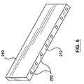
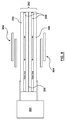
- FIGS. 6 and 7 show an alternate arrangement of a haptic feedback generator as described herein.
- a plurality of bilayer material strips 202 are shown assembled in a parallel configuration in a cavity 702 (see FIG. 7 ) of the haptic feedback generator, and are also shown disposed between two thermal energy sources/sinks (210/212), e.g., a hot source on first sides of the plurality of strips and a cold source on second sides of the plurality of strips.
- FIG. 7 shows a cutaway view where thermal energy sources/sinks 210/212 of the haptic feedback generator have been removed and bilayer material strips 202 are pictured.
- FIG. 2 provides a sectional view of an exemplary bilayer material strip 202 of the plurality of bilayer material strips shown in the embodiment of FIGS. 6 and 7 .
- the bilayer material strips as shown are ultrathin strips (straight or having some curvature) made, as described herein, of two different materials with two different coefficients of thermal expansion. They are arranged in a parallel configuration.
- bilayer material strips can be used, suitably 2 or more, more suitably about 2 to about 100 bilayer material strips, or about 10 to about 100, about 20 to about 100, about 20 to about 50, or about 10, about 20, about 30, about 40, about 50, about 60, about 70, about 80, about 90 or about 100 bilayer material strips.
- the bilayer material strips may have similar or varying thicknesses, suitably in the range of about 10 ⁇ m to 100 ⁇ m.
- such methods comprise increasing the temperature of a first thermal energy source/sink in the haptic feedback generator system, thereby increasing the temperature of a bilayer material strip in the system.
- the methods further comprise deflecting the bilayer material strip between a first position and a second position to generate haptic feedback to the user.
- increasing the temperature of the first thermal energy source/sink involves transferring thermal energy from the user to the first thermal energy source/sink as a result of the user's contact with the haptic feedback generator system (i.e., a passive temperature change as described herein).
- increasing the temperature of the first thermal energy source/sink utilizes heating the first thermal energy source/sink, triggered by the user's contact with the haptic feedback generator (i.e., an active temperature change as described herein).
- the methods further include transferring thermal energy from the bilayer material strip to a second energy source/sink, when the user ceases contact with the haptic feedback generator, and deflecting the bilayer material strip from the second position to the first position.
- thermal energy is transferred from the bilayer material strip to a second thermal energy source/sink, when the user ceases contact with the haptic feedback generator, and deflecting the bilayer material strip from the second position to the first position.
Landscapes
- Engineering & Computer Science (AREA)
- General Engineering & Computer Science (AREA)
- Theoretical Computer Science (AREA)
- Human Computer Interaction (AREA)
- Physics & Mathematics (AREA)
- General Physics & Mathematics (AREA)
- User Interface Of Digital Computer (AREA)
- Thermotherapy And Cooling Therapy Devices (AREA)
- Cooling Or The Like Of Electrical Apparatus (AREA)
Applications Claiming Priority (1)
| Application Number | Priority Date | Filing Date | Title |
|---|---|---|---|
| US201562209820P | 2015-08-25 | 2015-08-25 |
Publications (1)
| Publication Number | Publication Date |
|---|---|
| EP3144778A1 true EP3144778A1 (en) | 2017-03-22 |
Family
ID=56800184
Family Applications (1)
| Application Number | Title | Priority Date | Filing Date |
|---|---|---|---|
| EP16185272.8A Withdrawn EP3144778A1 (en) | 2015-08-25 | 2016-08-23 | Bilayer haptic feedback actuator |
Country Status (5)
| Country | Link |
|---|---|
| US (2) | US10180725B2 (enExample) |
| EP (1) | EP3144778A1 (enExample) |
| JP (1) | JP2017045458A (enExample) |
| KR (1) | KR20170024564A (enExample) |
| CN (1) | CN106484095A (enExample) |
Families Citing this family (8)
| Publication number | Priority date | Publication date | Assignee | Title |
|---|---|---|---|---|
| FR3042289B1 (fr) * | 2015-10-13 | 2019-08-16 | Dav | Module d'interface tactile et procede de generation d'un retour haptique |
| US10210978B2 (en) * | 2017-01-26 | 2019-02-19 | Immersion Corporation | Haptic actuator incorporating conductive coil and moving element with magnets |
| US20180286189A1 (en) * | 2017-03-31 | 2018-10-04 | Immersion Corporation | Multi-stable haptic feedback systems |
| CN108874243B (zh) * | 2017-05-11 | 2021-11-12 | 京东方科技集团股份有限公司 | 触控面板、电子装置及其驱动方法 |
| GB201817980D0 (en) * | 2018-11-02 | 2018-12-19 | Cambridge Mechatronics Ltd | Haptic button with SMA |
| KR20210093268A (ko) * | 2018-12-07 | 2021-07-27 | 소니그룹주식회사 | 촉각 및 온도의 피드백 시스템 |
| CN110097805A (zh) * | 2019-03-28 | 2019-08-06 | 吴少博 | 一种钢琴学习手型辅助矫正装置 |
| US12299201B2 (en) * | 2021-04-13 | 2025-05-13 | The Texas A&M University System | Systems and methods for providing tactile feedback to a user |
Citations (1)
| Publication number | Priority date | Publication date | Assignee | Title |
|---|---|---|---|---|
| US20130241718A1 (en) * | 2012-03-16 | 2013-09-19 | Qualcomm Incorporated | Methods and devices for selectively controlling and varying surface texture and/or force levels on a mobile device using haptic feedback |
Family Cites Families (8)
| Publication number | Priority date | Publication date | Assignee | Title |
|---|---|---|---|---|
| JPH10214158A (ja) * | 1997-01-30 | 1998-08-11 | Ricoh Co Ltd | 入力装置 |
| US20020191011A1 (en) * | 2001-06-04 | 2002-12-19 | Firooz Rasouli | Virtual remote touch system |
| US20040037016A1 (en) * | 2002-08-26 | 2004-02-26 | Norio Kaneko | Complex functional device and method of manufacturing the same, and haptic information system and information input apparatus comprising that complex functional device |
| JP3937982B2 (ja) * | 2002-08-29 | 2007-06-27 | ソニー株式会社 | 入出力装置および入出力装置を有する電子機器 |
| US7193316B2 (en) * | 2004-12-16 | 2007-03-20 | Intel Corporation | Integrated circuit coolant microchannel with movable portion |
| JP4297385B1 (ja) * | 2008-01-17 | 2009-07-15 | 謙太 中村 | ピン出力装置の昇降ピン制動機構 |
| US8237324B2 (en) * | 2008-12-10 | 2012-08-07 | The Regents Of The University Of California | Bistable electroactive polymers |
| JP6133220B2 (ja) * | 2014-02-03 | 2017-05-24 | ソフトバンク株式会社 | 表示装置 |
-
2016
- 2016-08-18 US US15/239,955 patent/US10180725B2/en not_active Expired - Fee Related
- 2016-08-23 EP EP16185272.8A patent/EP3144778A1/en not_active Withdrawn
- 2016-08-24 CN CN201610711560.7A patent/CN106484095A/zh active Pending
- 2016-08-25 KR KR1020160108323A patent/KR20170024564A/ko not_active Withdrawn
- 2016-08-25 JP JP2016164240A patent/JP2017045458A/ja not_active Ceased
-
2018
- 2018-12-13 US US16/219,941 patent/US10372220B2/en not_active Expired - Fee Related
Patent Citations (1)
| Publication number | Priority date | Publication date | Assignee | Title |
|---|---|---|---|---|
| US20130241718A1 (en) * | 2012-03-16 | 2013-09-19 | Qualcomm Incorporated | Methods and devices for selectively controlling and varying surface texture and/or force levels on a mobile device using haptic feedback |
Non-Patent Citations (4)
| Title |
|---|
| ROMAN VITUSHINSKY ET AL: "Bistable Thin-Film Shape Memory Actuators for Applications in Tactile Displays", JOURNAL OF MICROELECTROMECHANICAL SYSTEMS, vol. 18, no. 1, 1 February 2009 (2009-02-01), IEEE SERVICE CENTER, US, pages 186 - 194, XP011240897, ISSN: 1057-7157, DOI: 10.1109/JMEMS.2008.2009816 * |
| S. BOISSEAU ET AL.: "Semi-flexible Bimetal-based Thermal Energy Harvesters", SMART MATER. STRUCT., vol. 22, 025021, 25 January 2013 (2013-01-25), pages 1 - 8, XP002765750, DOI: 10.1088/0964-1726/22/2/025021 * |
| S. BOISSEAU ET AL.: "Semi-flexible Bimetalbased Thermal Energy Harvesters", SMART MATER. STRUCT., vol. 22, 2013, pages 025021 |
| TIMOSHENKO, S.: "Analysis of Bi-Metal Thermostats", JOURNAL OF THE OPTICAL SOCIETY OF AMERICA, vol. 11, 1925, pages 233 - 255 |
Also Published As
| Publication number | Publication date |
|---|---|
| KR20170024564A (ko) | 2017-03-07 |
| CN106484095A (zh) | 2017-03-08 |
| US20190121438A1 (en) | 2019-04-25 |
| JP2017045458A (ja) | 2017-03-02 |
| US10180725B2 (en) | 2019-01-15 |
| US10372220B2 (en) | 2019-08-06 |
| US20170060243A1 (en) | 2017-03-02 |
Similar Documents
| Publication | Publication Date | Title |
|---|---|---|
| US10372220B2 (en) | Bilayer haptic feedback actuator | |
| US7372348B2 (en) | Stressed material and shape memory material MEMS devices and methods for manufacturing | |
| TWI825478B (zh) | 用於製造基於微機電系統之冷卻系統的方法及系統 | |
| US7498715B2 (en) | Method and structure for an out-of plane compliant micro actuator | |
| Lee et al. | A micromachined refreshable Braille cell | |
| US6407482B2 (en) | Micro-relay and method for manufacturing the same | |
| US9181933B2 (en) | Temperature control device with a passive thermal feedback control valve | |
| US20110073788A1 (en) | Microvalve for control of compressed fluids | |
| US20110073188A1 (en) | Microvalve for control of compressed fluids | |
| KR20060048668A (ko) | 열 전달 장치와 그 동작 및 제조 방법 | |
| AbuZaiter et al. | Thermomechanical behavior of bulk NiTi shape-memory-alloy microactuators based on bimorph actuation | |
| Elbuken et al. | Design and analysis of a polymeric photo-thermal microactuator | |
| Dai et al. | Design and fabrication of a metal-silicon actuator with low voltage, low power consumption and large displacement | |
| US20180114659A1 (en) | Mechanical heat switch and method | |
| Hsu et al. | A two-way membrane-type micro-actuator with continuous deflections | |
| Huang et al. | Design, testing, and simulation of NiTi shape-memory-alloy thin-film-based microgrippers | |
| EP1494867B1 (en) | Thermoelastic inkjet actuator with heat conductive pathways | |
| Lau et al. | An in-plane thermal unimorph using confined polymers | |
| Suma et al. | Design and characterization of MEMS thermal actuator | |
| JP5707884B2 (ja) | マイクロポンプ及びこれを用いた半導体装置 | |
| Lau et al. | Optimum design of polymeric thermal microactuator with embedded silicon skeleton | |
| Demicoli et al. | Design and analysis of a MEMS-based electrothermal microgripper | |
| Shin et al. | Operating frequency of thin film NiTi in fluid media | |
| Hamedi et al. | A New MEMS assembly unit for hybrid self micropositioning and forced microclamping of submilimeter parts | |
| Paalvast et al. | Fast response thermal linear motor with reduced power consumption |
Legal Events
| Date | Code | Title | Description |
|---|---|---|---|
| PUAI | Public reference made under article 153(3) epc to a published international application that has entered the european phase |
Free format text: ORIGINAL CODE: 0009012 |
|
| STAA | Information on the status of an ep patent application or granted ep patent |
Free format text: STATUS: THE APPLICATION HAS BEEN PUBLISHED |
|
| AK | Designated contracting states |
Kind code of ref document: A1 Designated state(s): AL AT BE BG CH CY CZ DE DK EE ES FI FR GB GR HR HU IE IS IT LI LT LU LV MC MK MT NL NO PL PT RO RS SE SI SK SM TR |
|
| AX | Request for extension of the european patent |
Extension state: BA ME |
|
| STAA | Information on the status of an ep patent application or granted ep patent |
Free format text: STATUS: REQUEST FOR EXAMINATION WAS MADE |
|
| 17P | Request for examination filed |
Effective date: 20170921 |
|
| RBV | Designated contracting states (corrected) |
Designated state(s): AL AT BE BG CH CY CZ DE DK EE ES FI FR GB GR HR HU IE IS IT LI LT LU LV MC MK MT NL NO PL PT RO RS SE SI SK SM TR |
|
| STAA | Information on the status of an ep patent application or granted ep patent |
Free format text: STATUS: EXAMINATION IS IN PROGRESS |
|
| 17Q | First examination report despatched |
Effective date: 20180129 |
|
| STAA | Information on the status of an ep patent application or granted ep patent |
Free format text: STATUS: THE APPLICATION IS DEEMED TO BE WITHDRAWN |
|
| 18D | Application deemed to be withdrawn |
Effective date: 20200812 |