EP3144686A1 - Dispositif personnel de protection et methode pour detecter des champs electriques et/ou tension - Google Patents
Dispositif personnel de protection et methode pour detecter des champs electriques et/ou tension Download PDFInfo
- Publication number
- EP3144686A1 EP3144686A1 EP15380038.8A EP15380038A EP3144686A1 EP 3144686 A1 EP3144686 A1 EP 3144686A1 EP 15380038 A EP15380038 A EP 15380038A EP 3144686 A1 EP3144686 A1 EP 3144686A1
- Authority
- EP
- European Patent Office
- Prior art keywords
- electric field
- protective device
- personal protective
- movement
- variation
- Prior art date
- Legal status (The legal status is an assumption and is not a legal conclusion. Google has not performed a legal analysis and makes no representation as to the accuracy of the status listed.)
- Withdrawn
Links
Images

Classifications
-
- G—PHYSICS
- G01—MEASURING; TESTING
- G01R—MEASURING ELECTRIC VARIABLES; MEASURING MAGNETIC VARIABLES
- G01R29/00—Arrangements for measuring or indicating electric quantities not covered by groups G01R19/00 - G01R27/00
- G01R29/12—Measuring electrostatic fields or voltage-potential
-
- G—PHYSICS
- G01—MEASURING; TESTING
- G01R—MEASURING ELECTRIC VARIABLES; MEASURING MAGNETIC VARIABLES
- G01R15/00—Details of measuring arrangements of the types provided for in groups G01R17/00 - G01R29/00, G01R33/00 - G01R33/26 or G01R35/00
- G01R15/08—Circuits for altering the measuring range
-
- G—PHYSICS
- G01—MEASURING; TESTING
- G01R—MEASURING ELECTRIC VARIABLES; MEASURING MAGNETIC VARIABLES
- G01R15/00—Details of measuring arrangements of the types provided for in groups G01R17/00 - G01R29/00, G01R33/00 - G01R33/26 or G01R35/00
- G01R15/14—Adaptations providing voltage or current isolation, e.g. for high-voltage or high-current networks
- G01R15/16—Adaptations providing voltage or current isolation, e.g. for high-voltage or high-current networks using capacitive devices
- G01R15/165—Adaptations providing voltage or current isolation, e.g. for high-voltage or high-current networks using capacitive devices measuring electrostatic potential, e.g. with electrostatic voltmeters or electrometers, when the design of the sensor is essential
Definitions
- the present invention relates generally to the sector of devices for measuring electric fields and/or voltage.
- the invention particularly relates to a personal protective device for detecting electric fields and/or voltage, for example, of the type used in jobs involving an electrical hazard that can be found in most operations performed in medium- and high-voltage electrical installations.
- the proposed device operates as a safety device against possible accidents due to electric arcs or shocks from a live physical point to a nearby operator.
- the personal protective device can be worn by a user in a protective helmet, for example.
- the invention also relates to a method which comprises implementing a detection and warning strategy using the personal protective device as a safety element against electrical shock hazards.
- Devices existing on the market measure the electric field and generate a warning signal if it exceeds a predetermined threshold.
- the electric field is by definition the ratio between voltage and distance
- a field meter alone is not capable of discriminating between a high-voltage generator located far way or a low-voltage generator located nearby with respect to the operator, because the result of the ratio can be the same in the two circumstances and it may be dangerous in one case and not dangerous in another.
- Some of the known protective devices are therefore not effective.
- Another common feature of the existing detectors is directionality. There are preferred directions and blind directions in terms of detection capacity. Blind directions can cause dangerous situations for the user, particularly when such directions point to the back of the operator to be protected.
- omni-directionality in detection is a feature that would significantly increase user safety.
- Patent application EP1296150 discloses a portable electric field detector having a housing mountable on a user and including a sensing circuit responsive to an electric field to generate a signal which varies in proportion to the strength of the detected electric field, and an alarm circuit coupled to the detection circuit for producing an intermittent alarm signal with a repetition rate varying in proportion to the strength of the electric field.
- Patent document JP-B2-3421826 discloses a charge detector provided for being installed on the wrist of an operator.
- the detector comprises a detector body incorporating a circuit for detecting a microcurrent electrostatically induced in a human body when the latter approaches a charged part of a high-voltage machine housed in a metallic housing through a first capacitance formed between the charged part and a detection electrode and a second capacitance formed between the human body and the earth.
- the detector circuit also includes a circuit generating an alarm signal based on a detection signal.
- utility model CN2172479 discloses a safety helmet for high-voltage line operators, which has incorporated therein an alarm system, consisting of an audible message to keep operators out of the danger zone. Said system is activated by the induction of the electric field and the electronic components forming it.
- An object of the invention is to provide therefore a personal protective device for detecting electric fields and/or voltage, said device being located away from live electrical equipment or systems, being omni-directional and having a safety indication, preventing the drawbacks of earlier detectors and offering additional structural and operative advantages.
- the invention relates to a personal protective device for detecting electric fields and/or voltage of the type used as a safety element against electrical hazards which comprises, like detectors known in the state of the art, a housing holding an electric circuit provided for being incorporated on a user to be protected and preferably incorporated in a protective helmet of the user, and the mentioned electric circuit including acquisition means for acquiring electric field measuring signals responsive to the variation in strength of a detected electric field and alarm means (or element/module/device/unit) whereby a warning signal is generated.
- the personal protective device further comprises at least one movement measuring element for measuring the movement of the mentioned personal device.
- the mentioned electric circuit is connected to a control unit, such as a programmable integrated circuit or microcontroller, for processing the variation experienced by the personal protective device with respect to the detected electric field.
- the acquisition means for acquiring electric field measuring signals include two capacitive sensors acting in parallel, each including at least one charge amplifier and a step of conditioning the acquired electric field measuring signals.
- the acquisition means comprise only one capacitive sensor and one charge amplifier.
- the capacitive sensor or sensors can be sized to be responsive to different electric field values.
- the mentioned control unit can receive information about the movement of the personal protective device and control the actuation of the mentioned alarm means depending on the variation in the electric field and on the movement.
- the alarm means can be acoustic means, visual means, vibrating means, or a combination thereof.
- the movement measuring element comprises at least one accelerometer.
- the present invention also relates to a method for detecting electric fields and/or voltage which comprises using a personal protective device as a safety element against electrical hazards, wherein the mentioned personal protective device comprises an electric circuit including acquisition means for acquiring electric field measuring signals responsive to the variation in strength of a detected electric field, and alarm means whereby a warning signal is generated.
- the proposed method is characterized in that it calculates a variation in the electric field experienced by the personal protective device incorporated on a user and contemporaneously measures any movement of the personal device, as a result of a movement of said user.
- the calculation of the variation in the electric field is performed continuously.
- the calculation of the variation in the electric field and the measurement of movement are performed in the personal device itself.
- said calculation can be performed in a computing device located away from the personal device, the computing device being wirelessly connected to the personal device.
- the variation in the electric field can comprise the calculation of a derivative obtained from a consecutive sequence of electric field values acquired by the personal device, the alarm means being able to be controlled depending on said calculation of a derivative and on said measured movement of the personal device.
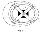
- the present invention provides a personal protective device 10, referred to in this description as an element for detecting electric fields and/or voltage, as well as a method by means of using the mentioned personal protective device 10, said device being for individual use by a user, located away from live electrical equipment or systems, omni-directional and providing a safety indication of the detected electric fields and/or voltage.
- FIG. 1 shows one embodiment of the proposed personal protective device 10, in this case incorporated in a protective helmet 1.
- the personal protective device 10 in this particular case comprises a housing holding therein an electric circuit including (see Figure 2 ) acquisition means 12 (alternating current or AC means) for acquiring electric field measuring signals (AC signals) responsive to the variation in strength of a detected electric field (and/or detected voltage) and alarm means or alarm device 11 (visual, acoustic, vibrating, etc.) generating a warning signal when the strength of the detected electric field exceeds a specific threshold value.
- acquisition means 12 alternating current or AC means
- AC signals electric field measuring signals
- alarm means or alarm device 11 visual, acoustic, vibrating, etc.
- the personal protective device 10 includes a movement measuring element 14 for measuring the movement of the personal protective device 10, for example, an accelerometer (without this being limiting since any element capable of measuring movement can be used), and a control unit 13, such as a microcontroller, connected to the electric circuit, for processing the acquired electric field measuring signals and calculating, preferably by means of computing the derivative of the consecutive sequence of the acquired/measured electric field values, the variation experienced by the personal protective device 10 with respect to the detected electric field (and/or detected voltage).
- a movement measuring element 14 for measuring the movement of the personal protective device 10
- an accelerometer without this being limiting since any element capable of measuring movement can be used
- a control unit 13 such as a microcontroller
- the personal protective device 10 allows, when the user approaches an electric field having a high strength comprised between 10 kV - 66 kV, for example, and goes over a threshold distance, about 1 meter for 10 kV and 3 meters for 66 kV, the personal protective device 10, by means of the alarm means 11, maintaining a warning signal (visual, acoustic, vibrating, etc.) to indicate to the user that (s)he is in a danger zone.
- the mentioned warning signal does not stop until the user moves away from the voltage source.
- the warning signal is kept active only for a specific time period. In this last case, the warning signal is repeated if the user has not moved away from the voltage source, i.e., if the movement measuring element 14 has not detected a variation in the movement of the user, and accordingly of the personal protective device 10.
- the mentioned acquisition means 12 in this case consist of two capacitive sensors S1, S2 connected in parallel and acting as antennas, each of them including a capacitor PCB1, PCB2 and a charge amplifier IC2, IC5 and a signal conditioner IC3-IC4, IC6-IC7.
- This dual configuration (use of two capacitive sensors in parallel) firstly allows broadening the range of use of the personal protective device 10, and secondly allows detecting situations in which a strong electric field due to a far away source masks a weaker electric field due to a nearby source, and it is this weaker electric field that actually generates a dangerous situation.
- the location of the two capacitive sensors S1, S2, sized for electric field levels occurring in operations in medium- and high-voltage electrical installations allows capturing electric fields affecting the user generated both by nearby and far away sources, regardless of the direction of origin. Therefore, the omni-directionality feature is supported in the personal protective device 10.
- processing of the data or electric field measuring signals by the control unit 13 allows calculating not only the variation in the electric field experienced by the personal protective device 10, but also the distance of the source generating it and the voltage level of said source.
- the first sensor S1 includes a capacitor PCB1 and a charge amplifier (operational amplifier) IC2.
- this operational amplifier IC2 by means of the negative feedback provided by C17, the charge induced in capacitor PCB1 due to the external electric field is obtained as voltage at the IC2 output (in low impedance) and can be analogically processed by the peak detector formed by IC3 and IC4 and diodes D2.
- the capacitor C21 maintains the peak value (positive maximum) of the AC signal of the IC2 output throughout successive cycles.
- the resistor R21 allows the capacitor C21 to discharge and to therefore follow the new IC2 output voltage maximum if the amplitude of the AC signal decreases (due to the decrease in the external field).
- the time constant resulting from the configuration of the resistor R21 in parallel with the capacitor C21 is about 1 second, so the response to the decrease in electric field is slow and the system responds smoothly to variations in the external electric field.
- this second sensor S2 is similar to the first sensor S1, with the particularity that the impedance values of the capacitors C17 and C3 are different, the capacity of C3 being less than the capacity of C17.
- the capacity of C17 By modifying the capacity of C17, in this case reducing it, the charge and discharge of the capacitor will be quicker. This situation is necessary for detecting high electric fields, since with more electric field, the circuit of the first sensor S1 will behave like the circuit of the second sensor S2, thereby preventing it from becoming saturated and preventing the signal from being non-interpretable.
- the mentioned acquisition means 12 only consist of a capacitive sensor and a charge amplifier.
- the operation with a single capacitive sensor is the same as the operation described above for two capacitive sensors.
- the proposed personal protective device 10 is preferably powered by cells or batteries which can be included in the housing itself.
Landscapes
- Physics & Mathematics (AREA)
- General Physics & Mathematics (AREA)
- Measurement Of The Respiration, Hearing Ability, Form, And Blood Characteristics Of Living Organisms (AREA)
Priority Applications (1)
| Application Number | Priority Date | Filing Date | Title |
|---|---|---|---|
| EP15380038.8A EP3144686A1 (fr) | 2015-09-18 | 2015-09-18 | Dispositif personnel de protection et methode pour detecter des champs electriques et/ou tension |
Applications Claiming Priority (1)
| Application Number | Priority Date | Filing Date | Title |
|---|---|---|---|
| EP15380038.8A EP3144686A1 (fr) | 2015-09-18 | 2015-09-18 | Dispositif personnel de protection et methode pour detecter des champs electriques et/ou tension |
Publications (1)
| Publication Number | Publication Date |
|---|---|
| EP3144686A1 true EP3144686A1 (fr) | 2017-03-22 |
Family
ID=54293200
Family Applications (1)
| Application Number | Title | Priority Date | Filing Date |
|---|---|---|---|
| EP15380038.8A Withdrawn EP3144686A1 (fr) | 2015-09-18 | 2015-09-18 | Dispositif personnel de protection et methode pour detecter des champs electriques et/ou tension |
Country Status (1)
| Country | Link |
|---|---|
| EP (1) | EP3144686A1 (fr) |
Cited By (1)
| Publication number | Priority date | Publication date | Assignee | Title |
|---|---|---|---|---|
| EP4016094A1 (fr) | 2020-12-18 | 2022-06-22 | Peek GmbH | Procédé et dispositif de détection des tensions électriques et/ou des courants électriques |
Citations (6)
| Publication number | Priority date | Publication date | Assignee | Title |
|---|---|---|---|---|
| CN2172479Y (zh) | 1993-06-17 | 1994-07-20 | 天津铁路分局古冶水电段工会职工技术协会 | 语言式近电报警安全帽 |
| EP1296150A1 (fr) | 2001-09-25 | 2003-03-26 | HD Electric Company | Détecteur de champs électriques portable |
| JP3421826B2 (ja) | 1995-02-10 | 2003-06-30 | 関西電力株式会社 | 手首装着式充電検出器 |
| US20060139031A1 (en) * | 2004-12-23 | 2006-06-29 | David Kalokitis | Sensor for sensing an electric field |
| ES1082733U (es) * | 2013-05-22 | 2013-06-18 | Sofamel, S.A. | Dispositivo personal de detección de campos eléctricos |
| CN104062488A (zh) * | 2014-07-09 | 2014-09-24 | 国网上海市电力公司 | 一种安全帽专用高压线路型预警器 |
-
2015
- 2015-09-18 EP EP15380038.8A patent/EP3144686A1/fr not_active Withdrawn
Patent Citations (6)
| Publication number | Priority date | Publication date | Assignee | Title |
|---|---|---|---|---|
| CN2172479Y (zh) | 1993-06-17 | 1994-07-20 | 天津铁路分局古冶水电段工会职工技术协会 | 语言式近电报警安全帽 |
| JP3421826B2 (ja) | 1995-02-10 | 2003-06-30 | 関西電力株式会社 | 手首装着式充電検出器 |
| EP1296150A1 (fr) | 2001-09-25 | 2003-03-26 | HD Electric Company | Détecteur de champs électriques portable |
| US20060139031A1 (en) * | 2004-12-23 | 2006-06-29 | David Kalokitis | Sensor for sensing an electric field |
| ES1082733U (es) * | 2013-05-22 | 2013-06-18 | Sofamel, S.A. | Dispositivo personal de detección de campos eléctricos |
| CN104062488A (zh) * | 2014-07-09 | 2014-09-24 | 国网上海市电力公司 | 一种安全帽专用高压线路型预警器 |
Cited By (2)
| Publication number | Priority date | Publication date | Assignee | Title |
|---|---|---|---|---|
| EP4016094A1 (fr) | 2020-12-18 | 2022-06-22 | Peek GmbH | Procédé et dispositif de détection des tensions électriques et/ou des courants électriques |
| DE102020134199A1 (de) | 2020-12-18 | 2022-06-23 | PEEK GmbH | Verfahren und vorrichtung zur detektion von elektrischen spannungen und/oder elektrischen strömen |
Similar Documents
| Publication | Publication Date | Title |
|---|---|---|
| KR102592177B1 (ko) | 에너지 검출 경고 디바이스 | |
| CN103344818B (zh) | 非接触式验电器和验电方法 | |
| EP3144686A1 (fr) | Dispositif personnel de protection et methode pour detecter des champs electriques et/ou tension | |
| CN101766355A (zh) | 可调式近电报警安全帽 | |
| CN207301108U (zh) | 一种自调节式非接触式电压检测装置 | |
| CN206348903U (zh) | 一种高压电磁安全预警系统 | |
| CN105411051B (zh) | 一种电力手套绝缘方法 | |
| JP2010206980A (ja) | 警報表示方法 | |
| CN212137105U (zh) | 一种智能化防触电安全信息综合采集终端 | |
| TR201714442A2 (tr) | Uyari si̇stemi̇, kontrol yöntemi̇ ve kontrolör | |
| CN207263819U (zh) | 一种便携型任意粘扣的工作服近电报警装置 | |
| CN203799473U (zh) | 可测电力安全距离安全带 | |
| CN105242126B (zh) | 一种高轨道卫星静电放电监测装置 | |
| CN209149534U (zh) | 高压输电线路防碰撞在线监测系统 | |
| CN207473019U (zh) | 一种110kV或220kV变电站跨步电压检测绝缘鞋 | |
| CN207232240U (zh) | 一种防触电报警电路以及手腕式近电报警装置 | |
| CN204203339U (zh) | 防触电装置 | |
| KR20130066062A (ko) | 감전사고 예방 작업복 | |
| CN110562550A (zh) | 一种温控离子风式化工粉体包装过程静电检测消除装置 | |
| CN218127167U (zh) | 矿用安全帽 | |
| CN202819759U (zh) | 振动式近电报警安全帽 | |
| CN201312570Y (zh) | 可调式近电报警安全帽 | |
| CN201328403Y (zh) | 可调式近电报警安全帽 | |
| KR20140065632A (ko) | 아몰퍼스 코어를 이용한 활선 접근 경보 장치 | |
| CN104515930A (zh) | 漏电检测报警电路 |
Legal Events
| Date | Code | Title | Description |
|---|---|---|---|
| PUAI | Public reference made under article 153(3) epc to a published international application that has entered the european phase |
Free format text: ORIGINAL CODE: 0009012 |
|
| AK | Designated contracting states |
Kind code of ref document: A1 Designated state(s): AL AT BE BG CH CY CZ DE DK EE ES FI FR GB GR HR HU IE IS IT LI LT LU LV MC MK MT NL NO PL PT RO RS SE SI SK SM TR |
|
| AX | Request for extension of the european patent |
Extension state: BA ME |
|
| 17P | Request for examination filed |
Effective date: 20170615 |
|
| RBV | Designated contracting states (corrected) |
Designated state(s): AL AT BE BG CH CY CZ DE DK EE ES FI FR GB GR HR HU IE IS IT LI LT LU LV MC MK MT NL NO PL PT RO RS SE SI SK SM TR |
|
| 17Q | First examination report despatched |
Effective date: 20200122 |
|
| STAA | Information on the status of an ep patent application or granted ep patent |
Free format text: STATUS: THE APPLICATION IS DEEMED TO BE WITHDRAWN |
|
| 18D | Application deemed to be withdrawn |
Effective date: 20200603 |