EP3144210A1 - Wakesurfing boat - Google Patents
Wakesurfing boat Download PDFInfo
- Publication number
- EP3144210A1 EP3144210A1 EP16187939.0A EP16187939A EP3144210A1 EP 3144210 A1 EP3144210 A1 EP 3144210A1 EP 16187939 A EP16187939 A EP 16187939A EP 3144210 A1 EP3144210 A1 EP 3144210A1
- Authority
- EP
- European Patent Office
- Prior art keywords
- starboard
- port
- boat
- transom
- hull
- Prior art date
- Legal status (The legal status is an assumption and is not a legal conclusion. Google has not performed a legal analysis and makes no representation as to the accuracy of the status listed.)
- Withdrawn
Links
- 230000003247 decreasing effect Effects 0.000 claims description 2
- XLYOFNOQVPJJNP-UHFFFAOYSA-N water Substances O XLYOFNOQVPJJNP-UHFFFAOYSA-N 0.000 description 12
- 238000006073 displacement reaction Methods 0.000 description 8
- 239000007789 gas Substances 0.000 description 5
- 238000005086 pumping Methods 0.000 description 5
- 230000003068 static effect Effects 0.000 description 5
- 244000221110 common millet Species 0.000 description 4
- 230000005923 long-lasting effect Effects 0.000 description 4
- 239000002352 surface water Substances 0.000 description 4
- 230000005484 gravity Effects 0.000 description 3
- JTJMJGYZQZDUJJ-UHFFFAOYSA-N phencyclidine Chemical compound C1CCCCN1C1(C=2C=CC=CC=2)CCCCC1 JTJMJGYZQZDUJJ-UHFFFAOYSA-N 0.000 description 3
- 230000007423 decrease Effects 0.000 description 2
- 230000003993 interaction Effects 0.000 description 2
- 239000007921 spray Substances 0.000 description 2
- 241000287828 Gallus gallus Species 0.000 description 1
- 230000001133 acceleration Effects 0.000 description 1
- 230000009286 beneficial effect Effects 0.000 description 1
- 230000033228 biological regulation Effects 0.000 description 1
- 230000005540 biological transmission Effects 0.000 description 1
- 239000012530 fluid Substances 0.000 description 1
- 238000000034 method Methods 0.000 description 1
- 230000007704 transition Effects 0.000 description 1
Images


Classifications
-
- B—PERFORMING OPERATIONS; TRANSPORTING
- B63—SHIPS OR OTHER WATERBORNE VESSELS; RELATED EQUIPMENT
- B63B—SHIPS OR OTHER WATERBORNE VESSELS; EQUIPMENT FOR SHIPPING
- B63B1/00—Hydrodynamic or hydrostatic features of hulls or of hydrofoils
- B63B1/32—Other means for varying the inherent hydrodynamic characteristics of hulls
-
- B—PERFORMING OPERATIONS; TRANSPORTING
- B63—SHIPS OR OTHER WATERBORNE VESSELS; RELATED EQUIPMENT
- B63B—SHIPS OR OTHER WATERBORNE VESSELS; EQUIPMENT FOR SHIPPING
- B63B1/00—Hydrodynamic or hydrostatic features of hulls or of hydrofoils
- B63B1/02—Hydrodynamic or hydrostatic features of hulls or of hydrofoils deriving lift mainly from water displacement
- B63B1/04—Hydrodynamic or hydrostatic features of hulls or of hydrofoils deriving lift mainly from water displacement with single hull
- B63B1/042—Hydrodynamic or hydrostatic features of hulls or of hydrofoils deriving lift mainly from water displacement with single hull the underpart of which being partly provided with channels or the like, e.g. catamaran shaped
-
- B—PERFORMING OPERATIONS; TRANSPORTING
- B63—SHIPS OR OTHER WATERBORNE VESSELS; RELATED EQUIPMENT
- B63B—SHIPS OR OTHER WATERBORNE VESSELS; EQUIPMENT FOR SHIPPING
- B63B1/00—Hydrodynamic or hydrostatic features of hulls or of hydrofoils
- B63B1/02—Hydrodynamic or hydrostatic features of hulls or of hydrofoils deriving lift mainly from water displacement
- B63B1/04—Hydrodynamic or hydrostatic features of hulls or of hydrofoils deriving lift mainly from water displacement with single hull
- B63B1/08—Shape of aft part
-
- B—PERFORMING OPERATIONS; TRANSPORTING
- B63—SHIPS OR OTHER WATERBORNE VESSELS; RELATED EQUIPMENT
- B63B—SHIPS OR OTHER WATERBORNE VESSELS; EQUIPMENT FOR SHIPPING
- B63B13/00—Conduits for emptying or ballasting; Self-bailing equipment; Scuppers
-
- B—PERFORMING OPERATIONS; TRANSPORTING
- B63—SHIPS OR OTHER WATERBORNE VESSELS; RELATED EQUIPMENT
- B63B—SHIPS OR OTHER WATERBORNE VESSELS; EQUIPMENT FOR SHIPPING
- B63B34/00—Vessels specially adapted for water sports or leisure; Body-supporting devices specially adapted for water sports or leisure
- B63B34/70—Arrangements on vessels specially adapted for generating waves for surfing, wakeboarding or the like, e.g. ballast tanks
-
- B—PERFORMING OPERATIONS; TRANSPORTING
- B63—SHIPS OR OTHER WATERBORNE VESSELS; RELATED EQUIPMENT
- B63H—MARINE PROPULSION OR STEERING
- B63H1/00—Propulsive elements directly acting on water
- B63H1/02—Propulsive elements directly acting on water of rotary type
- B63H1/12—Propulsive elements directly acting on water of rotary type with rotation axis substantially in propulsive direction
- B63H1/14—Propellers
- B63H1/26—Blades
-
- B—PERFORMING OPERATIONS; TRANSPORTING
- B63—SHIPS OR OTHER WATERBORNE VESSELS; RELATED EQUIPMENT
- B63H—MARINE PROPULSION OR STEERING
- B63H21/00—Use of propulsion power plant or units on vessels
- B63H21/32—Arrangements of propulsion power-unit exhaust uptakes; Funnels peculiar to vessels
-
- B—PERFORMING OPERATIONS; TRANSPORTING
- B63—SHIPS OR OTHER WATERBORNE VESSELS; RELATED EQUIPMENT
- B63B—SHIPS OR OTHER WATERBORNE VESSELS; EQUIPMENT FOR SHIPPING
- B63B2207/00—Buoyancy or ballast means
- B63B2207/02—Variable ballast or buoyancy
-
- Y—GENERAL TAGGING OF NEW TECHNOLOGICAL DEVELOPMENTS; GENERAL TAGGING OF CROSS-SECTIONAL TECHNOLOGIES SPANNING OVER SEVERAL SECTIONS OF THE IPC; TECHNICAL SUBJECTS COVERED BY FORMER USPC CROSS-REFERENCE ART COLLECTIONS [XRACs] AND DIGESTS
- Y02—TECHNOLOGIES OR APPLICATIONS FOR MITIGATION OR ADAPTATION AGAINST CLIMATE CHANGE
- Y02T—CLIMATE CHANGE MITIGATION TECHNOLOGIES RELATED TO TRANSPORTATION
- Y02T70/00—Maritime or waterways transport
- Y02T70/10—Measures concerning design or construction of watercraft hulls
Definitions
- the present invention relates to a wakesurfing boat, having a hull configuration adapted to produce a relatively large, long-lasting, and well-shaped wave in the wake of the boat, on which a wakesurfer can ride on a surf board, similar to surfing on a natural ocean wave.
- Wakesurfing is a watersport that is rapidly growing in popularity.
- a wakesurfer being towed behind a boat, while standing on a surf board and holding onto a tow rope, rides on a wave created in the wake of the boat, similar, in some respects, to a waterskier or a wakeboarder.
- the boat should generate, in its wake, a wave that as closely as possible mimics a size, a shape of a face, a shape of a crest, and a duration, of an ocean wave.
- the wakesurfer unlike a waterskier or a wakeboarder, can release the tow rope, and ride the surf board on the crest and the face of the wake wave, traversing back and forth on the wake wave, similar to an ocean surfer.
- wakesurfers have been attempting to surf primarily in the wakes of existing cruising boats, waterskiing boats, and wakeboarding boats.
- a problem with attempting to wakesurf behind such traditional boats, however, is that such boats fail to generate sufficiently large, sufficiently well-shaped, and sufficiently long-lasting wake waves necessary to give the wakesurfer a long, satisfying ride.
- Traditional boats also release engine exhaust gases into the air in the surfing area in the wake of the boat, causing discomfort to the wakesurfer.
- a boat when passing through a body of water, creates separate waves that move in the boat's wake.
- separate wake waves originate, respectively, from the boat's bow, centerline, quarter, and stern.
- Each wake wave generally forms the arms of a V, with the source of the respective wake wave being at the point of the V (i.e., the boat), and transverse curled wave crests forming offset from the path of the boat.
- Wake wave height is a function of several factors, including for example, a speed of the boat on the surface of the water, resistance to the boat as it moves through the water, a shape of the bottom of the hull, a length of the hull, a length/beam (L/B) ratio of the hull, a speed/length ratio (SLR) of the hull, a Froude number (Fr) of the hull, an amount of the bottom of the hull in contact with the body of water, hull displacement, hull trim, and an efficiency of the boat's propeller at the relatively high loads associated with wake surfing.
- a wakesurfing boat as depicted, disclosed, and claimed below, substantially obviates one or more of the shortcomings of the related art.
- a wakesurfing boat includes a hull, the hull having a bow, a stern, a transom positioned at the stern, a starboard bulwark, a port bulwark, a length L between the bow and the stern, a transom positioned at the stern, a beam B between the starboard and port bulwarks, a bottom, and a centerline CL extending between the bow and the stern.
- the boat moving through water, creates a wake with minimum losses when the hull has a L/B ratio of approximately 3.21, such as 3.21, with a rounded portion on the hull bottom proximate the transom.
- the rounded portion defines a fillet between the hull bottom and the starboard and port bulwarks proximate starboard and port points on the transom.
- the rounded portion on the hull bottom has a maximum radius related to the beam B of approximately 0.04(B), such as 0.04(B).
- the hull also has starboard and port arcuate portions defined on the starboard and port bulwarks, respectively, proximate the stern, extending outboard from the respective starboard and port points on the transom forward to respective starboard and port positions on the starboard and port bulwarks.
- the starboard and port arcuate portions each extend forward a distance equal to approximately 0.3(L), such as 0.3(L).
- the starboard and port arcuate portions define partial arcs of starboard and port ellipses, each ellipse defined by a major radius equal to 0.2(L) to 0.4(L), preferably 0.3(L) and a minor radius equal to 0.2(B) to 0.3(B), preferably 0.24(B).
- the respective starboard and port points on the transom are positioned spaced to starboard and port, respectively, of the CL.
- Each of the starboard and port points is spaced from the centerline by a distance equal to 0.26(B).
- the bottom of the hull defines an M-shaped portion, a V-shaped portion, a generally flat portion where the M-shaped portion meets the V-shaped portion, and a rounded portion proximate the transom.
- the M-shaped portion on the hull bottom extends from a position proximate the bow aft to a position located intermediate the bow and the stern, i.e., amidships, and more specifically, 0.4(L) to 0.5(L), measured aft from the bow.
- the V-shaped portion on the hull bottom extends from the transom to the amidships position, located approximately 0.4(L)-0.5(L) aft of the bow, such as 0.4(L)- 0.5(L) aft of the bow.
- an angle ⁇ is defined by the V-shaped portion of 10o. Angle ⁇ of the V-shaped portion decreases steadily to 7o at the amidships position where the hull bottom begins to transform into the M-shaped portion.
- the wakesurfing boat further includes a ballast system and a propulsion system.
- the propulsion system includes at least an engine and an exhaust pipe with an exhaust aperture.
- the exhaust pipe extends below the waterline of the hull and is attached to a wing-shaped body having a full wing profile between the bottom of the hull and the exhaust aperture.
- the exhaust aperture, through which the engine exhaust gases are omitted, is positioned forward of the transom.
- the propulsion system further includes a propeller.
- the propeller has a preselected disc area and a preselected blade area.
- the preselected blade area is larger than 70% of the preselected disc area.
- the boat's ballast system includes a plurality of ballast tanks, piping, and pumps for routing ballast water into the boat, between the ballast tanks, and overboard, as desired by a user of the boat.
- a controller operated by a boat operator, controls operation of both the ballast system and the propulsion system. The controller enables the boat operator to selectively change acceleration, speed, ballast, trim, and displacement, in order to operate the wakesurfing boat in different modes of operation, including at least a cruising mode, a static surfing mode, and a dynamic surfing mode.
- a wakesurfing boat 10 in accordance with the present invention, includes a hull 20.
- the hull 20 includes a bow 22, a stern 24, a transom 25 positioned at the stern, a starboard bulwark 26, a port bulwark 28, a centerline CL extending between the bow 22 and the stern 24 intermediate the starboard and port bulwarks 26, 28, a length L between the bow 22 and the stern 24, a beam B between the starboard bulwark 26 and the port bulwark 28, and a hull bottom 29.
- the length L of the hull is 13.37 meters.
- the maximum beam B is 4.54 meters. The actual preferred length L and beam B, however, will be selected to achieve a preferred length to beam (L/B) ratio, as discussed below.
- an M-shaped portion 30 is defined on the hull bottom 29.
- the M-shaped portion 30 includes a central vertex 32, defined by a keel line of the hull, a starboard vertex 34, a port vertex 36, a starboard nadir 37, and a port nadir 38.
- the bottom 29 of the hull 20 further includes a sheer line 132, first and second inner chines 134 and 136 on each of the starboard and port bulwarks, respectively (the chines on the starboard bulwark 26 are shown in Fig.
- the starboard and port vertices 34 and 36 of the M-shaped portion 30 correspond to forward portions of the first inner chines 136.
- the M-shaped portion 30 extends from the bow 22, along the bottom 29 of the hull 20, to a position P1, substantially amidships on the bottom 29 of the hull 20, between 0.4(L), and 0.5 (L) measured aft from the bow.
- the M-shaped portion 30 increases mass, and consequently increases efficient displacement, by trapping water and building up a bow wave between the starboard vertex 34 and the port vertex 36.
- the starboard and port vertices 34 and 36 also divide flow of the surface water under the bottom 29 of the hull 20, and direct spray towards the center of the bottom 29, thereby minimizing spray on the bulwarks of the hull 20 in the dynamic surfing mode M sd , thereby increasing the wave quality in the wake, leaving a more clean surface flowing aft, and providing a clean surface area to the wake wave.
- a V-shaped portion 40 is defined on the bottom 29 of the hull 20, extending from the transom 25 to the amidships position P1 where the bottom transforms into the M-shaped portion 30.
- the V-shaped portion 40 defines an angle ⁇ of 10o at the transom 25. Angle ⁇ decreases steadily along the length of the V-shaped portion 40 until it reaches an angle of 7o at amidships position P1.
- the transition of the V-shaped portion 40 to the M-shaped portion 30 at position P1 results in a section of the hull bottom which is relatively flat and nearly rectangular, a configuration which is beneficial for carrying an amount of ballast needed when the boat operates in the dynamic surfing mode M sd .
- the outer chine 138 transforms into a forward outer chine portion, and an aft outer chine portion.
- the first inner chine 134 converts into a forward first inner chine portion, and an aft first inner chine portion.
- the second inner chine 136 transforms into a forward second inner chine portion, and an aft second inner chine portion.
- the starboard and port forward second inner chine portions correspond to the starboard and port vertices 34 and 36, respectively, of the M-shaped portion 30.
- the combination of these bow, stern, and mid-hull configurations contributes to the capability of the hull 20 to carry a large quantity of ballast, and a wake wave having relatively high quality, quantified in height, steepness, and smoothness of the wave crest and wave face.
- the 10o angle at the transom 25 also assists in the creation of a large surfing wave.
- the hull 20 includes a preferred length to beam ratio L/B.
- a preferred L/B ratio is 2.9 to 3.65, preferably 3.1 to 3.3, and most preferably, in accordance with the invention, 3.21.
- the optimum L/B ratio of 3.21, with a rounded hull bottom proximate the transom, results in a closed wake wave.
- the closed wake wave meets a "rooster tail" of the wake, producing a diverging wake wave, with wave components W1 and W2 on starboard and port sides of the boat, respectively, as shown in Fig. 19 .
- This optimum L/B ratio combined with the rounded hull bottom proximate the transom, also results in the wake wave having minimum losses.
- a rounded portion 200 is defined on the bottom 29 of the hull 20, proximate the transom 25, thereby defining a fillet between the bottom 29 and the respective starboard and port bulwarks 26 and 28 at starboard and port points 55 and 56 defined on the transom 25.
- each of the starboard and port points 55 and 56 on the transom 25 are located, respectively, spaced to starboard and port of the centerline CL by an amount equal to 0.26(B), defining a total distance between the transom points 55 and 56 of 0.52(B).
- the rounded portion 200 as depicted in Fig. 10a , has a maximum radius relative to the beam B of 0.03(B) to 0.05(B), and most preferably 0.04(B). In the presently preferred embodiment, this maximum radius of 0.04(B) is equal to 154mm.
- the rounded portion 200 combined with the preferred L/B ratio of 3.21 minimizes losses due to turbulence in the wake wave.
- a portion of the aft hull body, proximate the stern 24, in a horizontal plane, is rounded, with the rounded aft hull body intersecting the transom 25 and the starboard and port bulwarks 26 and 28 of the hull 20.
- the hull 20 includes starboard and port arcuate portions 52 and 54, extending outboard from the respective starboard and port points 55 and 56 on the transom.
- the starboard and port arcuate portions 52 and 54 have generally partially-elliptical shapes each arcuate portion defining a partial arc of a respective starboard and port ellipse proximate the transom 25, as depicted in Fig. 9 , each of the ellipses being defined by a major radius equal to 0.2(L) to 0.4(L), preferably 0.3(L), and a minor radius equal to 0.2(B) to 0.3(B), preferably 0.24(B).
- the starboard and port arcuate portions 52 and 54 extend from the starboard and port transom points 55 and 56, forward to respective starboard and port positions 57 and 58 on the starboard and port bulwarks 26 and 28 of the hull 20.
- a preferred distance that the starboard and port arcuate portions 52 and 54, respectively, extend from the respective starboard and port transom points 55 and 56, to the respective starboard and port bulwark positions 57 and 58 is between 0.2(L)-0.4(L), preferably 0.3(L).
- the outboard rounding of the bulwarks 26 and 28 proximate the transom 25 increases the amount that the hull 20 sinks during the dynamic surfing mode M sd , thereby increasing hull displacement and resultant wake wave height.
- a ballast system 60 preferably includes six (6) ballast tanks, including a first ballast tank 62, a second ballast tank 64, a third ballast tank 65, a fourth ballast tank 66, a fifth ballast tank 67, and a sixth ballast tank 68, positioned at alternating positions above the hull bottom 29, adjacent the starboard and port bulwarks 26 and 28, between the stern 24 and the bow 22.
- Fig. 10 also depicts the position of the center of buoyancy CB of the hull 20.
- the first ballast tank 62 has a total capacity of 2,549 liters, a longitudinal center of gravity (LCG) of 1.81 meters, a vertical center of gravity (VCG) of 0.59 meters, and a transverse center of gravity (TCG) of 1.59 meters.
- the second ballast tank 64 has a total capacity of 2,549 liters, an LCG of 1.81 meters, a VCG of 0.59 meters, and a TCG of -1.59 meters.
- the third ballast tank 65 has a total capacity of 2,910 liters, an LCG of 7.65 meters, a VCG of 0.69 meters, and a TCG of 1.63 meters.
- the fourth ballast tank 66 has a total capacity of 2,910 liters, an LCG of 7.65 meters, a VCG of 0.69 meters, and a TCG of -1.63 meters.
- the fifth ballast tank 67 has a total capacity of 1,975 liters, an LCG of 10.72 meters, a VCG of 0.87 meters, and a TCG of 0.79 meters.
- the sixth ballast tank 68 has a total capacity of 1,975 liters, an LCG of 10.72 meters, a VCG of 0.87 meters, and a TCG of -0.79 meters.
- the ballast system 60 includes a ballast tank piping and pumping system 70.
- the ballast tank piping and pumping system 70 includes a plurality of ballast tank filling pipes 72, a plurality of ballast tank discharge pipes 74, and overflow vent pipes 77, with each of the various pipes 72, 74, 75, and 77 being associated with respective ballast tanks.
- the ballast tank piping, pumping, and control system 70 includes associated flow regulation valves, throttle valves, choke valves, and gate valves 76, ballast water pumps 78, and a controller 79.
- the controller 79 enables the operator of the wakesurfing boat 10 to manually or automatically control operation of the pumps 78 and valves 76, in order to selectively fill and drain various ballast tanks as desired.
- the configuration, and the principles of operation, of the automatically-controlled ballast piping and pumping system 70 are conventional, and known to persons of ordinary skill in the art, and therefore will not be further discussed here.
- a propulsion system 80 includes starboard and port engines 82 and 84, an engine exhaust discharge pipe 90, a propeller shaft (not shown), and a propeller 100.
- the controller 79 operated by the boat operator, in addition to controlling the ballast tank piping and pumping system 70, also controls the main engines 82 and 84 to regulate the speed of the wakesurfing boat 10.
- the speed of the wakesurfing boat 10, in combination with the ballast tank load, and the resultant trim and displacement of the wakesurfing boat 10, results in an ability to operate the boat 10 in different modes of operation, as explained below.
- the engine exhaust discharge pipe 90 extends from the transom 25 below the hull bottom 29 and offset from the centerline CL, with an exhaust opening 92 being defined in the exhaust pipe 100 mm forward of the transom 25.
- the exhaust from the engines 82 and 84 as a result, is released submerged in the water, and is carried aft in the wake wave aft of the hull 20, rather than being released and carried aft in the air aft of the hull 20.
- at least one wing-shaped portion 92 be attached to the exhaust pipe 90 between the exhaust pipe 90 and the hull bottom 29.
- the at least one wing-shaped portion 92 preferably has a portion with a height of approximately 120-150 mm, such as 120-150 mm, and a length approximately 4-5 times an outer diameter of the exhaust opening 92, such as 4-5 times an outer diameter of the exhaust opening 92.
- the propulsion system 80 includes a propeller 100.
- the propeller 100 includes a hub and at least three propeller blades 104.
- the hub and the blades define a disc102.
- the total area of the blades 104 defined by the projected blade area on the surface of the disc 102 defines a second area A2.
- Propulsion in the dynamic surfing mode M sd (discussed below) requires high efficiency at high load on the propeller. In the dynamic surfing mode M sd , the propeller 100 needs to propel the boat 10 up to an optimum surfing speed.
- Wakesurfing boat 10 in accordance with the invention, operating in the dynamic surfing mode M sd , with a large amount of ballast, enjoys maximum thrust and propeller efficiency because the second area A2, defined by a sum of the area of the projected area of the blades 104, is larger than 70% of the first area A 1 of the first circle C 1 defined by the disc 102.
- Use of a ducted propeller as the propeller 100 also is contemplated and within the scope of the invention.
- a cruising mode M c ( Fig. 16 )
- a static surfing mode M ss ( Fig. 17 )
- the dynamic surfing mode M sd ( Fig. 18 )
- a wake wave is created with an improved height, steepness, crest smoothness, face smoothness, and duration, all of which are very desirable for surfing.
- FIG. 19 graphically depicts a wave in the wake of the above-described preferred embodiment of the wakesurfing boat 10, in accordance with the invention, including a starboard wave component W1 and a port wave component W2, created by the wakesurfing boat 10 operating in the dynamic surfing mode M sd .
- Each of the wake wave components W1 and W2 defines a relatively large, relatively long-lasting, and relatively well-shaped wake wave, mimicking as closely as possible an ocean wave, thereby providing the wakesurfer a long satisfying surfing experience substantially similar to that of an ocean surfer.
Landscapes
- Chemical & Material Sciences (AREA)
- Engineering & Computer Science (AREA)
- Combustion & Propulsion (AREA)
- Mechanical Engineering (AREA)
- Ocean & Marine Engineering (AREA)
- Physics & Mathematics (AREA)
- Fluid Mechanics (AREA)
- Exhaust Silencers (AREA)
Abstract
Description
- The present invention relates to a wakesurfing boat, having a hull configuration adapted to produce a relatively large, long-lasting, and well-shaped wave in the wake of the boat, on which a wakesurfer can ride on a surf board, similar to surfing on a natural ocean wave.
- Wakesurfing is a watersport that is rapidly growing in popularity. A wakesurfer, being towed behind a boat, while standing on a surf board and holding onto a tow rope, rides on a wave created in the wake of the boat, similar, in some respects, to a waterskier or a wakeboarder. Ideally, the boat should generate, in its wake, a wave that as closely as possible mimics a size, a shape of a face, a shape of a crest, and a duration, of an ocean wave. If the wake wave reaches a sufficient size, shape, and duration, the wakesurfer, unlike a waterskier or a wakeboarder, can release the tow rope, and ride the surf board on the crest and the face of the wake wave, traversing back and forth on the wake wave, similar to an ocean surfer.
- Until now, wakesurfers have been attempting to surf primarily in the wakes of existing cruising boats, waterskiing boats, and wakeboarding boats. A problem with attempting to wakesurf behind such traditional boats, however, is that such boats fail to generate sufficiently large, sufficiently well-shaped, and sufficiently long-lasting wake waves necessary to give the wakesurfer a long, satisfying ride. Traditional boats also release engine exhaust gases into the air in the surfing area in the wake of the boat, causing discomfort to the wakesurfer.
- As is known in the field of fluid dynamics, a boat, when passing through a body of water, creates separate waves that move in the boat's wake. In general, separate wake waves originate, respectively, from the boat's bow, centerline, quarter, and stern. Each wake wave generally forms the arms of a V, with the source of the respective wake wave being at the point of the V (i.e., the boat), and transverse curled wave crests forming offset from the path of the boat. Wake wave height is a function of several factors, including for example, a speed of the boat on the surface of the water, resistance to the boat as it moves through the water, a shape of the bottom of the hull, a length of the hull, a length/beam (L/B) ratio of the hull, a speed/length ratio (SLR) of the hull, a Froude number (Fr) of the hull, an amount of the bottom of the hull in contact with the body of water, hull displacement, hull trim, and an efficiency of the boat's propeller at the relatively high loads associated with wake surfing.
- It is an object of the present invention to provide a wakesurfing boat that provides, in its wake, a relatively large, relatively long-lasting, and relatively well-shaped wake wave, mimicking as closely as possible an ocean wave, in order to give a wakesurfer a long satisfying surfing experience substantially similar to that of an ocean surfer.
- It is another object of the present invention to provide a wakesurfing boat and a hull for a wakesurfing boat capable of operating in separate modes, including a cruising mode, a static surfing mode, and a dynamic surfing mode.
- It is a further object of the invention to provide a wakesurfing boat, configured with a ballast system capable of moving ballast rapidly and efficiently, in order to change the trim and displacement of the boat rapidly and efficiently, to thereby rapidly and efficiently shift the modes of operation.
- It is a further object of the present invention to provide a wakesurfing boat configured to maximize wave resistance to the boat and the hull, to transform the power from the engine, and to maximize the efficiency of the propeller, in order to generate as much wave power as possible.
- It is a further object of the present invention to provide a wakesurfing boat configured to substantially prevent engine exhaust from being released behind the first wave crest and entering the air in the surfing area aft of the boat, thereby minimizing or preventing discomfort to the wakesurfer caused by the exhaust gases.
- These and other objects of the present invention will be apparent from review of the following specification and the accompanying drawings.
- In view of the above objectives of the invention, a wakesurfing boat as depicted, disclosed, and claimed below, substantially obviates one or more of the shortcomings of the related art.
- A wakesurfing boat includes a hull, the hull having a bow, a stern, a transom positioned at the stern, a starboard bulwark, a port bulwark, a length L between the bow and the stern, a transom positioned at the stern, a beam B between the starboard and port bulwarks, a bottom, and a centerline CL extending between the bow and the stern.
- The boat, moving through water, creates a wake with minimum losses when the hull has a L/B ratio of approximately 3.21, such as 3.21, with a rounded portion on the hull bottom proximate the transom. The rounded portion defines a fillet between the hull bottom and the starboard and port bulwarks proximate starboard and port points on the transom. The rounded portion on the hull bottom has a maximum radius related to the beam B of approximately 0.04(B), such as 0.04(B).
- The hull also has starboard and port arcuate portions defined on the starboard and port bulwarks, respectively, proximate the stern, extending outboard from the respective starboard and port points on the transom forward to respective starboard and port positions on the starboard and port bulwarks. The starboard and port arcuate portions each extend forward a distance equal to approximately 0.3(L), such as 0.3(L). The starboard and port arcuate portions define partial arcs of starboard and port ellipses, each ellipse defined by a major radius equal to 0.2(L) to 0.4(L), preferably 0.3(L) and a minor radius equal to 0.2(B) to 0.3(B), preferably 0.24(B).
- The respective starboard and port points on the transom are positioned spaced to starboard and port, respectively, of the CL. Each of the starboard and port points is spaced from the centerline by a distance equal to 0.26(B).
- The bottom of the hull defines an M-shaped portion, a V-shaped portion, a generally flat portion where the M-shaped portion meets the V-shaped portion, and a rounded portion proximate the transom.
- The M-shaped portion on the hull bottom extends from a position proximate the bow aft to a position located intermediate the bow and the stern, i.e., amidships, and more specifically, 0.4(L) to 0.5(L), measured aft from the bow.
- The V-shaped portion on the hull bottom extends from the transom to the amidships position, located approximately 0.4(L)-0.5(L) aft of the bow, such as 0.4(L)- 0.5(L) aft of the bow. At the transom, an angle α is defined by the V-shaped portion of 10º. Angle α of the V-shaped portion decreases steadily to 7º at the amidships position where the hull bottom begins to transform into the M-shaped portion.
- The wakesurfing boat further includes a ballast system and a propulsion system.
- The propulsion system includes at least an engine and an exhaust pipe with an exhaust aperture. The exhaust pipe extends below the waterline of the hull and is attached to a wing-shaped body having a full wing profile between the bottom of the hull and the exhaust aperture. The exhaust aperture, through which the engine exhaust gases are omitted, is positioned forward of the transom. As a result of the above combination of structural features, exhaust gases are emitted below the wake wave aft of the transom, not in the air of the surfing area aft of the transom.
- The propulsion system further includes a propeller. The propeller has a preselected disc area and a preselected blade area. The preselected blade area is larger than 70% of the preselected disc area.
- The boat's ballast system includes a plurality of ballast tanks, piping, and pumps for routing ballast water into the boat, between the ballast tanks, and overboard, as desired by a user of the boat. A controller, operated by a boat operator, controls operation of both the ballast system and the propulsion system. The controller enables the boat operator to selectively change acceleration, speed, ballast, trim, and displacement, in order to operate the wakesurfing boat in different modes of operation, including at least a cruising mode, a static surfing mode, and a dynamic surfing mode.
-
-
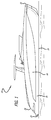
FIG. 1 is a side view of a wakesurfing boat in accordance with the invention; -
FIG. 2 is a top view of the wakesurfing boat in accordance with the invention; -
FIG. 3 is a front view of the wakesurfing boat in accordance with the invention; -
FIG. 4 is a rear top perspective view of the wakesurfing boat in accordance with the invention; -
FIG. 5a is a starboard side profile view of the wakesurfing boat in accordance with the invention, depicting locations along the length of the hull of spaced cross-sectional cuts A-O at preselected locations between them stern and the bow, respectively; -
FIG. 5b is an upper plan view of the wakesurfing boat in accordance with the invention, depicting the location of the spaced cross-sectional cuts shown inFig. 6 ; -
FIG. 6 is a body plan view of the wakesurfing boat in accordance with the invention, depicting the relative shape of each of the cross-sectional cuts A-O shown inFigs 5a and 5b ; -
Fig.7a is a front perspective view of a hull bottom in accordance with the invention; -
Fig. 7b is an upper perspective view depicting stern details of a hull in accordance with the invention; -
FIG. 8 is a graph depicting an optimum length to beam ratio L/B to obtain a large wave using the wakesurfing boat in accordance with the invention; -
Fig. 9 is a top view of the hull of the wakesurfing boat in accordance with the invention, proximate the stern, depicting laterally-projecting arcuate portions extending between starboard and port endpoints on the transom to respective starboard and port positions on the respective starboard and port bulwarks, configured to minimize losses from turbulence and speed gradients in the wake, each arcuate portion defining an arc of a respective ellipse; -
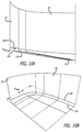
Fig. 10a is a side view of the stern of the wakesurfing boat in accordance with the invention, depicting a rounded stern portion connecting the hull bottom to the starboard bulwark and the transom; -
Fig. 10b is a side perspective view depicting the rounded stern portion ofFig. 10a ; -
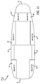
Fig. 11 is a top plan view depicting a preferred location of ballast tanks in the wakesurfing boat in accordance with the invention; -
Fig. 12a is a plan view depicting system details of ballast pipes and pumps, used with the ballast tanks depicted inFig. 11 in the wakesurfing boat in accordance with the invention; -
Fig. 12b is a cross-sectional view of a ballast tank ofFig. 11 , depicting a ballast filling and discharge principle for the ballast tank; -
Fig. 13 is a top plan view depicting a portion of a propulsion system in the wakesurfing boat in accordance with the invention, and an interaction of the propulsion system, and the ballast system in the wakesurfing boat in accordance with the invention; -
Fig. 14a is a side view depicting the configuration of an exhaust pipe in the wakesurfing boat in accordance with the invention, and the location of the exhaust pipe aperture in relation to the transom; -
Fig. 14b is a perspective view depicting the configuration of the exhaust pipe ofFig. 14a ; -
Fig. 15 is a front view of a propeller used in the wakesurfing boat in accordance with the invention; -
Fig. 16 is a side view of a wakesurfing boat in accordance with the invention, in a cruising mode; -
Fig. 17 is a side view of a wakesurfing boat in accordance with the invention, in a static surfing mode; -
Fig. 18 is a side view of a wakesurfing boat in accordance with the invention, in a dynamic surfing mode; and -
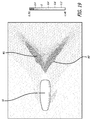
Fig. 19 is a top view graphically depicting a wave in the wake of a wakesurfing boat, in accordance with the invention, operating in a dynamic surfing mode. - Other embodiments of the invention will be apparent to those skilled in the art from consideration of the specification and practice of the invention disclosed herein. It is intended that the specification and examples be considered as exemplary only, with a true scope and spirit of the invention being indicated by the attached claims.
- In accordance with the invention, and as broadly embodied in
Figs. 1-7 , awakesurfing boat 10, in accordance with the present invention, includes ahull 20. Thehull 20 includes abow 22, a stern 24, atransom 25 positioned at the stern, astarboard bulwark 26, aport bulwark 28, a centerline CL extending between thebow 22 and the stern 24 intermediate the starboard and port bulwarks 26, 28, a length L between thebow 22 and the stern 24, a beam B between thestarboard bulwark 26 and theport bulwark 28, and ahull bottom 29. In one preferred embodiment, the length L of the hull is 13.37 meters. In one preferred embodiment, the maximum beam B is 4.54 meters. The actual preferred length L and beam B, however, will be selected to achieve a preferred length to beam (L/B) ratio, as discussed below. - In accordance with the invention, and as embodied in
Figs. 3 ,5a ,5b ,6 , and7a , an M-shapedportion 30 is defined on thehull bottom 29. The M-shapedportion 30 includes acentral vertex 32, defined by a keel line of the hull, astarboard vertex 34, aport vertex 36, astarboard nadir 37, and aport nadir 38. Referring toFigs. 5a and 5b , the bottom 29 of thehull 20 further includes asheer line 132, first and secondinner chines starboard bulwark 26 are shown inFig. 5a , and the chines on theport bulwark 28 are shown inFig. 5b ). Anouter chine 138 is also defined on each bulwark. The starboard andport vertices portion 30 correspond to forward portions of the firstinner chines 136. Referring toFig. 7a , the M-shapedportion 30 extends from thebow 22, along the bottom 29 of thehull 20, to a position P1, substantially amidships on the bottom 29 of thehull 20, between 0.4(L), and 0.5 (L) measured aft from the bow. The M-shapedportion 30 increases mass, and consequently increases efficient displacement, by trapping water and building up a bow wave between thestarboard vertex 34 and theport vertex 36. The starboard andport vertices hull 20, and direct spray towards the center of the bottom 29, thereby minimizing spray on the bulwarks of thehull 20 in the dynamic surfing mode Msd, thereby increasing the wave quality in the wake, leaving a more clean surface flowing aft, and providing a clean surface area to the wake wave. - In accordance with the invention, and as embodied in
Figs. 6 and7a , a V-shapedportion 40 is defined on the bottom 29 of thehull 20, extending from thetransom 25 to the amidships position P1 where the bottom transforms into the M-shapedportion 30. The V-shapedportion 40 defines an angle α of 10º at thetransom 25. Angle α decreases steadily along the length of the V-shapedportion 40 until it reaches an angle of 7º at amidships position P1. The transition of the V-shapedportion 40 to the M-shapedportion 30 at position P1 results in a section of the hull bottom which is relatively flat and nearly rectangular, a configuration which is beneficial for carrying an amount of ballast needed when the boat operates in the dynamic surfing mode Msd. At the position P1, theouter chine 138 transforms into a forward outer chine portion, and an aft outer chine portion. In addition, at position P1, the firstinner chine 134 converts into a forward first inner chine portion, and an aft first inner chine portion. Likewise, at position P1, the secondinner chine 136 transforms into a forward second inner chine portion, and an aft second inner chine portion. The starboard and port forward second inner chine portions correspond to the starboard andport vertices portion 30. The combination of these bow, stern, and mid-hull configurations contributes to the capability of thehull 20 to carry a large quantity of ballast, and a wake wave having relatively high quality, quantified in height, steepness, and smoothness of the wave crest and wave face. The 10º angle at thetransom 25 also assists in the creation of a large surfing wave. - In accordance with the invention, the
hull 20 includes a preferred length to beam ratio L/B. As embodied inFig. 8 , a preferred L/B ratio is 2.9 to 3.65, preferably 3.1 to 3.3, and most preferably, in accordance with the invention, 3.21. The optimum L/B ratio of 3.21, with a rounded hull bottom proximate the transom, results in a closed wake wave. The closed wake wave meets a "rooster tail" of the wake, producing a diverging wake wave, with wave components W1 and W2 on starboard and port sides of the boat, respectively, as shown inFig. 19 . This optimum L/B ratio, combined with the rounded hull bottom proximate the transom, also results in the wake wave having minimum losses. - As broadly embodied in
Figs. 5a, 5b ,7b ,10a, and 10b , arounded portion 200, between the aft portion of the firstinner chine 134 and the aft portion of theouter chine 138, is defined on the bottom 29 of thehull 20, proximate thetransom 25, thereby defining a fillet between the bottom 29 and the respective starboard and port bulwarks 26 and 28 at starboard and port points 55 and 56 defined on thetransom 25. Each of the starboard and port points 55 and 56 on thetransom 25 are located, respectively, spaced to starboard and port of the centerline CL by an amount equal to 0.26(B), defining a total distance between the transom points 55 and 56 of 0.52(B). In a preferred embodiment, therounded portion 200, as depicted inFig. 10a , has a maximum radius relative to the beam B of 0.03(B) to 0.05(B), and most preferably 0.04(B). In the presently preferred embodiment, this maximum radius of 0.04(B) is equal to 154mm. Therounded portion 200, combined with the preferred L/B ratio of 3.21 minimizes losses due to turbulence in the wake wave. - To further minimize losses in the wake wave from turbulence and large speed gradients, and in accordance with the invention, a portion of the aft hull body, proximate the stern 24, in a horizontal plane, is rounded, with the rounded aft hull body intersecting the
transom 25 and the starboard and port bulwarks 26 and 28 of thehull 20. In accordance with the invention, and as broadly embodied inFig. 9 , thehull 20 includes starboard and portarcuate portions arcuate portions transom 25, as depicted inFig. 9 , each of the ellipses being defined by a major radius equal to 0.2(L) to 0.4(L), preferably 0.3(L), and a minor radius equal to 0.2(B) to 0.3(B), preferably 0.24(B). The starboard and portarcuate portions port positions hull 20. A preferred distance that the starboard and portarcuate portions bulwarks hull 20 sinks during the dynamic surfing mode Msd, thereby increasing hull displacement and resultant wake wave height. - In accordance with the invention, and as broadly embodied in
Fig. 11 , aballast system 60 preferably includes six (6) ballast tanks, including afirst ballast tank 62, asecond ballast tank 64, athird ballast tank 65, afourth ballast tank 66, afifth ballast tank 67, and asixth ballast tank 68, positioned at alternating positions above the hull bottom 29, adjacent the starboard and port bulwarks 26 and 28, between the stern 24 and thebow 22.Fig. 10 also depicts the position of the center of buoyancy CB of thehull 20. Preferably, thefirst ballast tank 62 has a total capacity of 2,549 liters, a longitudinal center of gravity (LCG) of 1.81 meters, a vertical center of gravity (VCG) of 0.59 meters, and a transverse center of gravity (TCG) of 1.59 meters. Preferably, thesecond ballast tank 64 has a total capacity of 2,549 liters, an LCG of 1.81 meters, a VCG of 0.59 meters, and a TCG of -1.59 meters. Preferably, thethird ballast tank 65 has a total capacity of 2,910 liters, an LCG of 7.65 meters, a VCG of 0.69 meters, and a TCG of 1.63 meters. Preferably, thefourth ballast tank 66 has a total capacity of 2,910 liters, an LCG of 7.65 meters, a VCG of 0.69 meters, and a TCG of -1.63 meters. Preferably, thefifth ballast tank 67 has a total capacity of 1,975 liters, an LCG of 10.72 meters, a VCG of 0.87 meters, and a TCG of 0.79 meters. Preferably, thesixth ballast tank 68 has a total capacity of 1,975 liters, an LCG of 10.72 meters, a VCG of 0.87 meters, and a TCG of -0.79 meters. - As further broadly embodied in
Figs. 12a and 12b , theballast system 60 includes a ballast tank piping andpumping system 70. The ballast tank piping andpumping system 70 includes a plurality of ballasttank filling pipes 72, a plurality of ballasttank discharge pipes 74, andoverflow vent pipes 77, with each of thevarious pipes control system 70 includes associated flow regulation valves, throttle valves, choke valves, andgate valves 76, ballast water pumps 78, and acontroller 79. Thecontroller 79 enables the operator of thewakesurfing boat 10 to manually or automatically control operation of thepumps 78 andvalves 76, in order to selectively fill and drain various ballast tanks as desired. The configuration, and the principles of operation, of the automatically-controlled ballast piping andpumping system 70 are conventional, and known to persons of ordinary skill in the art, and therefore will not be further discussed here. - In accordance with the invention, and as broadly embodied in
Figs. 12-13 , a propulsion system 80 includes starboard andport engines exhaust discharge pipe 90, a propeller shaft (not shown), and apropeller 100. Thecontroller 79, operated by the boat operator, in addition to controlling the ballast tank piping andpumping system 70, also controls themain engines wakesurfing boat 10. The speed of thewakesurfing boat 10, in combination with the ballast tank load, and the resultant trim and displacement of thewakesurfing boat 10, results in an ability to operate theboat 10 in different modes of operation, as explained below. - In accordance with the invention, and as broadly embodied in
Fig.12 , the engineexhaust discharge pipe 90 extends from thetransom 25 below the hull bottom 29 and offset from the centerline CL, with anexhaust opening 92 being defined in theexhaust pipe 100 mm forward of thetransom 25. The exhaust from theengines hull 20, rather than being released and carried aft in the air aft of thehull 20. It is preferred that at least one wing-shapedportion 92 be attached to theexhaust pipe 90 between theexhaust pipe 90 and thehull bottom 29. The at least one wing-shapedportion 92 preferably has a portion with a height of approximately 120-150 mm, such as 120-150 mm, and a length approximately 4-5 times an outer diameter of theexhaust opening 92, such as 4-5 times an outer diameter of theexhaust opening 92. The above-described combination of structural features results in the wake wave closing above the exhaust gasses, thereby not allowing the exhaust gases to exit the water into the air in the wake of theboat 10, and hence avoiding discomfort to the wakesurfer. - In accordance with the invention, and as broadly embodied in
Fig. 15 , the propulsion system 80 includes apropeller 100. Thepropeller 100 includes a hub and at least threepropeller blades 104. The hub and the blades define a disc102. Thedisc 102 defines a first circle C1 having a first diameter D1, and a first area A1 = (Π/4) D1. The total area of theblades 104 defined by the projected blade area on the surface of thedisc 102, defines a second area A2. Propulsion in the dynamic surfing mode Msd (discussed below) requires high efficiency at high load on the propeller. In the dynamic surfing mode Msd, thepropeller 100 needs to propel theboat 10 up to an optimum surfing speed. This requires a large thrust at a relatively low speed, thereby placing a high load on theblades 104. Transmission of maximum thrust and power to the water requires a large blade area. In addition, if the blade area is too small, the water is unable to carry the load and will start to cavitate in the wake, reducing propeller efficiency and thrust.Wakesurfing boat 10, in accordance with the invention, operating in the dynamic surfing mode Msd, with a large amount of ballast, enjoys maximum thrust and propeller efficiency because the second area A2, defined by a sum of the area of the projected area of theblades 104, is larger than 70% of the first area A1 of the first circle C1 defined by thedisc 102. Use of a ducted propeller as thepropeller 100 also is contemplated and within the scope of the invention. - As embodied in
Figs. 16-19 , interaction of the ballast system and the propulsion system, with resultant changes in ballast volume, ballast weight, and boat displacement and trim, results in at least three different modes of operation for thewakesurfing boat 10, i.e., a cruising mode Mc (Fig. 16 ), with the ballast tanks empty, and theboat 10 being propelled through the surface water; a static surfing mode Mss (Fig. 17 ), with the ballast tanks in the process of filling, or full, and theboat 10 sitting static in the surface water; and the dynamic surfing mode Msd (Fig. 18 ), with the ballast tanks full, and theboat 10 being propelled through the surface water. In the dynamic surfing mode Msd, as a result of the greater hull displacement, greater propeller thrust, greater propeller efficiency, optimized L/B ratio, and minimized losses in the wake resulting from the rounded aft hull bottom and the rounded aft body hull, intersecting with the transom and the bulwarks, a wake wave is created with an improved height, steepness, crest smoothness, face smoothness, and duration, all of which are very desirable for surfing.Fig. 19 graphically depicts a wave in the wake of the above-described preferred embodiment of thewakesurfing boat 10, in accordance with the invention, including a starboard wave component W1 and a port wave component W2, created by thewakesurfing boat 10 operating in the dynamic surfing mode Msd. Each of the wake wave components W1 and W2 defines a relatively large, relatively long-lasting, and relatively well-shaped wake wave, mimicking as closely as possible an ocean wave, thereby providing the wakesurfer a long satisfying surfing experience substantially similar to that of an ocean surfer. -
- Features 1. A wakesurfing boat comprising: a hull, the hull comprising: a bow; a stern; a starboard bulwark; a port bulwark; a transom positioned at the stern, the transom having starboard and port points between the starboard and port bulwarks; a length L between the bow and the stern; a beam B between the starboard and port bulwarks; a bottom; a deck; a centerline extending between the bow and the stern midway between the port and starboard bulwarks; a rounded aft hull body intersecting the transom, the starboard bulwark, and the port bulwark, the rounded aft hull body including: a starboard arcuate portion extending outboard from the starboard bulwark proximate the stern, the starboard arcuate portion connecting the starboard point of the transom to a position on the starboard bulwark intermediate the starboard point on the transom and the bow, the starboard arcuate portion defining a partial arc of a starboard ellipse, the starboard ellipse defined on the deck at the starboard side of the hull proximate the stern, the starboard ellipse having a starboard major radius, the starboard major radius being equal to approximately 0.2(L) to 0.4(L), and a starboard minor radius, the starboard minor radius being equal to approximately 0.2(B) to 0.3(B); and a port arcuate portion extending outboard from the port bulwark proximate the stern, the port arcuate portion connecting the port point of the transom to a position on the port bulwark intermediate the port point on the transom and the bow, the port arcuate portion defining a partial arc of a port ellipse, the port ellipse defined on the deck at the port side of the hull proximate the stern, the port ellipse having a port major radius, the port major radius being equal to approximately 0.2(L) to 0.4(L), and a port minor radius, the port minor radius being equal to approximately 0.2(B) to 0.3(B);
wherein the starboard arcuate portion and the port arcuate portion intersect the starboard and port points on the transom, respectively to define a width between the starboard point of the transom and the port arc of the transom which is less than the beam B; and wherein the starboard partial arc of the starboard ellipse defining the starboard arcuate portion and the port partial arc of the port ellipse defining the port arcuate portion, thereby defining the rounded aft hull body, are configured to minimize losses in a wake wave; a ballast system; and a propulsion system. - Features 2. The wakesurfing boat of features 1, wherein the major radius of each of the starboard and port ellipses is equal to 0.3(L), and the minor radius is equal to 0.24(B).
- Features 3. The wakesurfing boat of any of the preceding features, further comprising a L/B ratio of approximately 3.1 to 3.3.
- Features 4. The wakesurfing boat of features 3, wherein the L/B ratio is equal to 3.21.
- Features 5. The wakesurfing boat of any of the preceding features, wherein the bottom comprises a substantial M-shaped portion and a substantial V-shaped portion.
- Features 6. The wakesurfing boat of any of the preceding features, wherein a length of each of the respective starboard and port positions on the respective starboard and port bulwarks, measured from the respective starboard and port points on the transom, is approximately 0.3(L).
- Features 7. The wakesurfing boat of any of the preceding features, wherein the respective
starboard and port points on the transom are located at respective starboard and port sides of the centerline, spaced away from the centerline by a distance equal to approximately 0.26(B). - Features 8. The wakesurfing boat of features 5, wherein the substantial M-shaped portion extends along the bottom of the hull from a first position proximate the bow to a second position located approximately 0.4(L) to approximately 0.5(L) aft of the bow.
- Features 9. The wakesurfing boat of features 8, wherein the substantial V-shaped portion extends from the transom to approximately the second position.
-
Features 10. The wakesurfing boat of features 8 or 9, wherein the substantial V-shaped portion defines an angle of approximately 10º at the stern, the angle decreasing to approximately 7º at the second position. - Features 11. The wakesurfing boat of any of the preceding features, wherein the propulsion system comprises at least an engine, an engine exhaust pipe with an exhaust opening, and a propeller.
- Features 12. The wakesurfing boat of features 11, wherein the propeller has a preselected blade area, and a preselected disc area, the preselected blade area being larger than 70% of the preselected disc area.
- Features 13. The wakesurfing boat of any of the preceding features, further comprising a rounded portion on the bottom proximate the transom, the rounded portion having a maximum radius related to the beam B, and defining a fillet between the bottom and the starboard and port bulwarks proximate the starboard and port points on the transom.
- Features 14. The wakesurfing boat of features 13, wherein a maximum radius of the rounded portion on the bottom related to the beam B is 0.03(B) to 0.05 (B). Features 15. The wakesurfing boat of any of the preceding features, wherein the width between the starboard point on the transom and the port point on the transom is approximately 0.52(B).
Claims (15)
- A wakesurfing boat comprising:a hull, the hull comprising:a transom positioned at the stern, the transom having starboard and port points between the starboard and port bulwarks;a bow;a stern;a starboard bulwark; a port bulwark;
a length L between the bow and the stern;a beam B between the starboard and port bulwarksa bottom;a deck;a centerline (32) extending between the bow and the stern midway betweenthe port and starboard bulwarks;a rounded aft hull body intersecting the transom, the starboard bulwark, and the port bulwark, the rounded aft hull body including:a first inner chine (134), a second inner chine (136) and an outer chine (138) with a rounded portion (200) lying between an aft portion of the first inner chine (134) and an aft portion of the outer chine (138) on the bottom (29) of the hull 20 proximate the transom (25) thereby defining the rounded aft hull body configured to minimize losses in a wake wave;a ballast system; anda propulsion system. - The boat of claim 1, wherein the rounded portion (200) defines a fillet between the bottom (29) and the respective starboard and port bulwarks (26,28).
- The boat of any preceding claim, wherein the rounded portion (200) has a maximum radius, Rmax between the first inner chine and the outer chine, relative to the beam B of 0.03(B) to 0.05(B) and most preferably 0.04(B).
- The boat of any preceding claim, wherein at a position P1, substantially amidships on the bottom (29) of the hull (20), between 0.4(L), and 0.5(L) measured aft from the bow, the first inner chine (134) converges with the outer chine (138).
- The wakesurfing boat of any preceding claim, further comprising a L/B ratio of approximately 3.1 to 3.3.
- The wakesurfing boat of claim 5, wherein the L/B ratio is equal to 3.21.
- The wakesurfing boat of any preceding claim, wherein the bottom comprises a substantial M-shaped portion and a substantial V-shaped portion.
- The wakesurfing boat of any preceding claim, wherein a length of each of the respective starboard and port positions on the respective starboard and port bulwarks, measured from the respective starboard and port points on the transom, is approximately 0.3(L).
- The wakesurfing boat of any preceding claim, wherein the respective star
board and port points on the transom are located at respective starboard andport sides of the centerline, spaced away from the centerline by a distance equal to approximately 0.26(B). - The wakesurfing boat of claim 6, wherein the substantial M-shaped portion extends along the bottom of the hull from a first position proximate the bow to a second position located approximately 0.4(L) to approximately 0.5(L) aft of the bow and preferably the substantial V-shaped portion extends from the transom to approximately the second position.
- The wakesurfing boat of claim 7 or 8, wherein the substantial V-shaped portion defines an angle of approximately 10º at the stern, the angle decreasing to approximately 7º at the second position.
- The wakesurfing boat of any preceding claim, wherein the propulsion system comprises at least an engine, an engine exhaust pipe with an exhaust opening, and a propeller, preferably the propeller has a preselected blade area, and a preselected disc area, the preselected blade area being larger than 70% of the preselected disc area.
- The wakesurfing boat of any preceding claim, wherein the rounded portion has a maximum radius related to the beam B, and defines the fillet between the bottom and the starboard and port bulwarks proximate the starboard and port points on the transom.
- The wakesurfing boat of claim 13, wherein a maximum radius of the rounded portion on the bottom related to the beam B is 0.03(B) to 0.05 (B).
- The wakesurfing boat of any of the preceding claims, wherein the width between the starboard point on the transom and the port point on the transom is approximately 0.52(B).
Applications Claiming Priority (2)
| Application Number | Priority Date | Filing Date | Title |
|---|---|---|---|
| US14/676,305 US9242700B1 (en) | 2015-04-01 | 2015-04-01 | Wakesurfing boat |
| EP16163389.6A EP3075646A1 (en) | 2015-04-01 | 2016-03-31 | Wakesurfing boat |
Related Parent Applications (1)
| Application Number | Title | Priority Date | Filing Date |
|---|---|---|---|
| EP16163389.6A Division EP3075646A1 (en) | 2015-04-01 | 2016-03-31 | Wakesurfing boat |
Publications (1)
| Publication Number | Publication Date |
|---|---|
| EP3144210A1 true EP3144210A1 (en) | 2017-03-22 |
Family
ID=55071352
Family Applications (2)
| Application Number | Title | Priority Date | Filing Date |
|---|---|---|---|
| EP16187939.0A Withdrawn EP3144210A1 (en) | 2015-04-01 | 2016-03-31 | Wakesurfing boat |
| EP16163389.6A Withdrawn EP3075646A1 (en) | 2015-04-01 | 2016-03-31 | Wakesurfing boat |
Family Applications After (1)
| Application Number | Title | Priority Date | Filing Date |
|---|---|---|---|
| EP16163389.6A Withdrawn EP3075646A1 (en) | 2015-04-01 | 2016-03-31 | Wakesurfing boat |
Country Status (2)
| Country | Link |
|---|---|
| US (2) | US9242700B1 (en) |
| EP (2) | EP3144210A1 (en) |
Families Citing this family (10)
| Publication number | Priority date | Publication date | Assignee | Title |
|---|---|---|---|---|
| CN103121495B (en) * | 2013-02-20 | 2015-09-02 | 陈振诚 | A kind of Water traffic transportation tool |
| US10422267B2 (en) | 2016-11-16 | 2019-09-24 | Benjamin Quinby | Marine rudder exhaust system |
| US11254391B2 (en) * | 2017-09-01 | 2022-02-22 | Mastercraft Boat Company, Llc | Ballast system for a boat and method of operating a boat |
| AU2019311094A1 (en) * | 2018-07-24 | 2021-02-11 | Running Tide Technologies, Inc. | System and method for the cultivation of aquatic animals |
| USD895525S1 (en) * | 2018-09-07 | 2020-09-08 | Bombardier Recreational Products Inc. | Watercraft bow |
| US10518842B1 (en) | 2018-11-15 | 2019-12-31 | James H. Kyle | Boat hull |
| CN110450903B (en) * | 2019-07-05 | 2021-04-27 | 哈尔滨工程大学 | A longitudinal flow transition type semi-planing boat |
| USD981322S1 (en) | 2021-02-18 | 2023-03-21 | Bombardier Recreational Products Inc. | Watercraft hull |
| USD974274S1 (en) * | 2021-04-27 | 2023-01-03 | Saxdor Yachts Oy | Boat |
| USD969053S1 (en) * | 2021-06-24 | 2022-11-08 | Optima Projects Ltd | Boat hull |
Citations (2)
| Publication number | Priority date | Publication date | Assignee | Title |
|---|---|---|---|---|
| EP2602178A1 (en) * | 2011-12-09 | 2013-06-12 | 3Madmen | Wakesurfing boat and hull for a wakesurfing boat with ballast system. |
| EP2778038A2 (en) * | 2013-03-15 | 2014-09-17 | 3Madmen | Wakesurfing boat and hull for a wakesurfing boat |
Family Cites Families (89)
| Publication number | Priority date | Publication date | Assignee | Title |
|---|---|---|---|---|
| US1316762A (en) | 1919-09-23 | bigelow | ||
| US652876A (en) | 1899-04-17 | 1900-07-03 | Cipriano Andrade Jr | Hull for ships or boats. |
| US1204355A (en) | 1914-03-12 | 1916-11-07 | William Albert Hickman | Motor-boat. |
| US1644725A (en) | 1922-10-23 | 1927-10-11 | Hickman William Albert | Boat |
| US1620349A (en) | 1923-01-10 | 1927-03-08 | Hickman William Albert | Boat |
| US1681342A (en) | 1923-01-10 | 1928-08-21 | Hickman William Albert | Boat |
| US1670623A (en) | 1923-01-10 | 1928-05-22 | Hickman William Albert | Boat |
| US2285959A (en) | 1939-10-10 | 1942-06-09 | Alphonse A Dubay | Hull construction |
| US2515005A (en) | 1945-05-03 | 1950-07-11 | Hickman William Albert | Boat |
| US2423796A (en) | 1946-03-06 | 1947-07-08 | Jr Lester B Platt | Hydroplane |
| US3191572A (en) | 1963-08-21 | 1965-06-29 | Wilson Henry Allen | Reduced friction hull construction for power boats |
| US3330239A (en) | 1964-09-03 | 1967-07-11 | Henry J Dornak | Boat hull with tunneled v-bottom |
| US3200782A (en) | 1964-11-06 | 1965-08-17 | Samuel L Walden | Power boat attachment |
| FR1432674A (en) | 1965-02-08 | 1966-03-25 | Navili S A R L | Boat |
| US3503358A (en) | 1968-10-29 | 1970-03-31 | Carl Moesly | Self-stabilizing boat hull |
| US3709179A (en) | 1970-07-06 | 1973-01-09 | Wyle Laboratories | High speed boat |
| US3675605A (en) | 1970-07-29 | 1972-07-11 | Hugh S Knerr | Ship or boat hull construction |
| US3797437A (en) | 1971-11-22 | 1974-03-19 | Exxon Research Engineering Co | Water ballast arrangement for externally insulated tankers |
| US3902445A (en) | 1972-07-11 | 1975-09-02 | Leonard Dirk Stolk | Air-cushioned planing hull |
| US3800725A (en) | 1973-03-30 | 1974-04-02 | Heureux R L | Boat hull |
| US4192248A (en) | 1978-01-23 | 1980-03-11 | Moyer Richard D | Scooped boat hull having tri-keel surfaces |
| US4478166A (en) | 1980-12-22 | 1984-10-23 | Sorensen George C | Boat |
| AU95503S (en) | 1986-01-09 | 1987-03-12 | Boat hull | |
| USD306631S (en) | 1987-04-10 | 1990-03-13 | Aguilar John J | Towed watercraft |
| CA1315158C (en) | 1987-04-30 | 1993-03-30 | John A. Lund | Water craft |
| US5664910A (en) | 1987-05-27 | 1997-09-09 | Light Wave, Ltd. | Boat activated wave generator |
| IT212308Z2 (en) | 1987-07-01 | 1989-07-04 | Akzo Srl | MOTOR BOAT |
| JPH0195991A (en) | 1987-10-07 | 1989-04-14 | Busco Roberto & Co Snc | Tank installed to keel for ship in longitudinal direction |
| USD302969S (en) | 1987-10-19 | 1989-08-22 | Pipkorn Howard W | Boat hull |
| USD318041S (en) | 1988-05-27 | 1991-07-09 | Meredith Wilbur R | Boat hull |
| US5231949A (en) | 1990-05-08 | 1993-08-03 | Robert Hadley | Dihedral tunnel boat hull |
| US5215025A (en) | 1990-07-10 | 1993-06-01 | K10 Corporation | Boat |
| US5265554A (en) | 1992-06-23 | 1993-11-30 | Meredith Marine, Inc. | Boat construction |
| US5351641A (en) | 1993-02-09 | 1994-10-04 | Scott Robson | Boat hull construction |
| CA2101912C (en) | 1993-08-04 | 1997-03-25 | Peter J. Van Diepen | Planing boat hull form |
| USD355881S (en) | 1993-09-28 | 1995-02-28 | Carlson Arthur E | Boat hull |
| US5526762A (en) | 1994-02-15 | 1996-06-18 | Kiley; John C. | Power planing catamaran |
| US5427048A (en) | 1994-03-01 | 1995-06-27 | Takeuchi; Richard T. | Multi-concave hydrodynamically designed hull |
| US5458078A (en) | 1994-06-29 | 1995-10-17 | Perette; Robert J. | High speed catamaran hull and boat |
| US5474014A (en) | 1995-03-16 | 1995-12-12 | Russell; Daniel N. | Non-linear tunnel hull boat |
| US5549071A (en) | 1995-07-03 | 1996-08-27 | Tige Boats | Ski tow boat with wake control device and method for operation |
| USD382850S (en) | 1996-07-01 | 1997-08-26 | Schmidt William J | Tri-hull boat |
| USD400156S (en) | 1996-07-26 | 1998-10-27 | Arthur Herbert Duvenage | Boat hull exterior |
| US5655473A (en) | 1996-09-06 | 1997-08-12 | Lynn Davis Nebel | Boat hull |
| US5718184A (en) | 1996-11-21 | 1998-02-17 | Holland; Herbert A. | Hydro-lift boat hull |
| US6105527A (en) | 1996-12-18 | 2000-08-22 | Light Wave Ltd. | Boat activated wake enhancement method and system |
| AUPO521597A0 (en) | 1997-02-19 | 1997-04-11 | John Young Developments Pty. Ltd. | Boat hulls |
| US6374762B1 (en) | 1997-10-27 | 2002-04-23 | Correct Craft, Inc. | Water sport towing apparatus |
| US6192819B1 (en) | 1997-10-27 | 2001-02-27 | Correct Craft, Inc. | Water sport towing apparatus |
| US5860384A (en) | 1997-12-02 | 1999-01-19 | Castillo; James D. | Wake control apparatus |
| USD405411S (en) | 1998-01-30 | 1999-02-09 | Schmidt William J | Boat hull |
| JPH11248462A (en) | 1998-03-04 | 1999-09-17 | Alps Electric Co Ltd | Vibratory gyroscope |
| US6006689A (en) | 1998-04-28 | 1999-12-28 | Profjord Ab | Arrangement for dynamic control of running trim and list of a boat |
| USD418104S (en) | 1998-09-08 | 1999-12-28 | Vittorio Bove | Boat hull |
| US6250245B1 (en) | 1998-09-22 | 2001-06-26 | Mangia Onda Co., Llc | M-shaped boat hull |
| US6314903B2 (en) | 1998-09-22 | 2001-11-13 | Mangia Onda Co., Llc | M-shaped boat hull |
| US6526903B2 (en) | 1998-09-22 | 2003-03-04 | Mangia Onda Co., Llc | High speed M-shaped boat hull |
| US6047657A (en) | 1999-07-19 | 2000-04-11 | Cox; Steve Jon | Surfable wave making device |
| US6293216B1 (en) | 1999-11-16 | 2001-09-25 | Bruce R. Barsumian | Surface effect ship (SES) hull configuration having improved high speed performance and handling characteristics |
| US6604478B2 (en) | 1999-11-16 | 2003-08-12 | Bruce R. Barsumian | Hull configuration utilizing multiple effects for enhanced speed, range and efficiency |
| FR2808250B1 (en) | 2000-04-28 | 2002-08-16 | Stephane Chollet | PLANING HULL MOTOR BOAT |
| US6708642B1 (en) | 2002-02-22 | 2004-03-23 | Reflex Advanced Marine Corp. | Tri-sponson boat hull and method of making boat hulls |
| US7328668B2 (en) | 2002-10-07 | 2008-02-12 | Roger Gamble Doughty Guérard | Hybrid vee-hull / wing-in-ground effect vessel |
| US6868798B2 (en) | 2003-07-23 | 2005-03-22 | M Ship Co., Llc. | Powered watercraft |
| US7093553B2 (en) | 2003-07-23 | 2006-08-22 | M Ship Co., Llc. | Super high speed multi-hull watercraft |
| US6983713B1 (en) | 2003-07-23 | 2006-01-10 | M Ship Co., Llc. | Powered watercraft |
| GB2419115B (en) | 2003-07-30 | 2008-05-28 | Buddie Gordon Miller | Slotted Hulls For Boats |
| US6941884B2 (en) | 2003-12-15 | 2005-09-13 | Steven Clay Moore | Wake control mechanism |
| US7063031B2 (en) | 2004-05-28 | 2006-06-20 | Pivotal Designs Inc. | Wake control device for boat |
| US7578250B2 (en) | 2005-01-03 | 2009-08-25 | Baker Elbert H | Watercraft with wave deflecting hull |
| US20090308300A1 (en) | 2005-01-03 | 2009-12-17 | Baker Elbert H | Watercraft with wave deflecting hull |
| US7316193B1 (en) | 2005-04-29 | 2008-01-08 | Hydroeye Marine Group, Llc | Vessel for water travel |
| US7305926B2 (en) | 2005-06-10 | 2007-12-11 | Seider Dennis J | Ported tri-hull boat |
| US7458332B2 (en) | 2005-07-22 | 2008-12-02 | Jim Wilson | High speed marine vessel |
| US7252047B1 (en) | 2005-09-20 | 2007-08-07 | Baucom Jr Donald L | Wave-forming apparatus for boats |
| US7625153B2 (en) | 2006-02-14 | 2009-12-01 | Sauerbier Charles E | Floating oceanic surfing reef |
| US7418915B2 (en) | 2006-03-15 | 2008-09-02 | Navatek, Ltd. | Entrapment tunnel monohull optimized waterjet and high payload |
| US7677192B2 (en) | 2006-04-20 | 2010-03-16 | Randy Scism | Slot-V hull system |
| USD570278S1 (en) | 2007-02-01 | 2008-06-03 | Alan Horais | Hull for catamaran type windsurfing vessel |
| JP5143510B2 (en) | 2007-09-11 | 2013-02-13 | 国好 笹山 | Hull structure |
| USD581340S1 (en) | 2007-11-30 | 2008-11-25 | Chaparral Boats, Inc. | Boat Hull |
| NO333766B1 (en) | 2007-12-07 | 2013-09-16 | Marine Roll & Pitch Control As | System and method for active and passive stabilization of vessel |
| CN102015437B (en) | 2008-03-12 | 2013-10-09 | 汉弗莱有限责任公司 | Arrangement for dynamic control of running trim and list of a boat |
| US8109221B2 (en) | 2008-08-20 | 2012-02-07 | Aspen Power Catamarans Llc | Single drive catamaran hull |
| USD595204S1 (en) | 2008-09-10 | 2009-06-30 | Robinson Charles W | M-shaped boat hull |
| US8281730B2 (en) | 2010-02-04 | 2012-10-09 | William Munson | Watercraft with asymmetrical and symmetrical boat hull |
| USD651551S1 (en) | 2010-12-02 | 2012-01-03 | Moore Boats, LLC | Boat hull |
| USD643357S1 (en) | 2010-12-02 | 2011-08-16 | Moore Boats, LLC | Boat hull |
| US8590475B2 (en) | 2011-12-09 | 2013-11-26 | 3Madmen | Wakesurfing boat and hull for a wakesurfing boat |
-
2015
- 2015-04-01 US US14/676,305 patent/US9242700B1/en active Active
- 2015-06-22 US US14/746,125 patent/US9238499B1/en active Active
-
2016
- 2016-03-31 EP EP16187939.0A patent/EP3144210A1/en not_active Withdrawn
- 2016-03-31 EP EP16163389.6A patent/EP3075646A1/en not_active Withdrawn
Patent Citations (2)
| Publication number | Priority date | Publication date | Assignee | Title |
|---|---|---|---|---|
| EP2602178A1 (en) * | 2011-12-09 | 2013-06-12 | 3Madmen | Wakesurfing boat and hull for a wakesurfing boat with ballast system. |
| EP2778038A2 (en) * | 2013-03-15 | 2014-09-17 | 3Madmen | Wakesurfing boat and hull for a wakesurfing boat |
Also Published As
| Publication number | Publication date |
|---|---|
| US9238499B1 (en) | 2016-01-19 |
| EP3075646A1 (en) | 2016-10-05 |
| US9242700B1 (en) | 2016-01-26 |
Similar Documents
| Publication | Publication Date | Title |
|---|---|---|
| US9238499B1 (en) | Wakesurfing boat | |
| US7997221B2 (en) | Apparatus for reducing drag on a nautical vessel | |
| KR101348081B1 (en) | Air cavity and air lubrication type ship with stern of step shape forming at propeller area | |
| US7581508B2 (en) | Monohull fast ship or semi-planing monohull with a drag reduction method | |
| US8955451B2 (en) | Foil structure for providing buoyancy and lift | |
| US10518842B1 (en) | Boat hull | |
| CN101484351A (en) | Ship | |
| US8857364B2 (en) | Wakesurfing boat and hull for a wakesurfing boat | |
| US10988210B2 (en) | Hybrid chine boat hull and methods of manufacture and use | |
| CN102171093B (en) | Hull form intended for vessels provided with an air cavity | |
| CN111836758A (en) | inflatable motor boat | |
| RU2364544C2 (en) | Method of high-speed cruising and ship to this end (versions) | |
| CN102958791B (en) | Method for moving a ship in water and ship moving in water according to said method | |
| US8813672B2 (en) | Swimming platform for a boat | |
| RU2527244C1 (en) | Aft end of two-shaft vessel | |
| US20210316817A1 (en) | Hybrid chine boat hull and methods of manufacture and use | |
| US9193423B2 (en) | Hull configuration for submarines and vessel of the displacement type with multihull structure | |
| US12179883B2 (en) | Hybrid chine boat hull and methods of manufacture and use | |
| RU2302356C2 (en) | Hull of ship provided with central keel and side bilges | |
| KR102612234B1 (en) | Hull type of planning vessel with Air Lubricating System | |
| CN203832700U (en) | Marine cruise | |
| RU144285U1 (en) | Hull of a Gliding Ship | |
| US2303437A (en) | Means for the propulsion of ships | |
| RU2499721C1 (en) | Ship tunnel-type hull | |
| WO2017069673A1 (en) | Boat hull |
Legal Events
| Date | Code | Title | Description |
|---|---|---|---|
| PUAI | Public reference made under article 153(3) epc to a published international application that has entered the european phase |
Free format text: ORIGINAL CODE: 0009012 |
|
| AC | Divisional application: reference to earlier application |
Ref document number: 3075646 Country of ref document: EP Kind code of ref document: P |
|
| AK | Designated contracting states |
Kind code of ref document: A1 Designated state(s): AL AT BE BG CH CY CZ DE DK EE ES FI FR GB GR HR HU IE IS IT LI LT LU LV MC MK MT NL NO PL PT RO RS SE SI SK SM TR |
|
| AX | Request for extension of the european patent |
Extension state: BA ME |
|
| STAA | Information on the status of an ep patent application or granted ep patent |
Free format text: STATUS: THE APPLICATION IS DEEMED TO BE WITHDRAWN |
|
| 18D | Application deemed to be withdrawn |
Effective date: 20170923 |