EP3144131A1 - Tire manufacturing method - Google Patents
Tire manufacturing method Download PDFInfo
- Publication number
- EP3144131A1 EP3144131A1 EP16183373.6A EP16183373A EP3144131A1 EP 3144131 A1 EP3144131 A1 EP 3144131A1 EP 16183373 A EP16183373 A EP 16183373A EP 3144131 A1 EP3144131 A1 EP 3144131A1
- Authority
- EP
- European Patent Office
- Prior art keywords
- ply
- layered body
- turning
- end portions
- layering
- Prior art date
- Legal status (The legal status is an assumption and is not a legal conclusion. Google has not performed a legal analysis and makes no representation as to the accuracy of the status listed.)
- Withdrawn
Links
Images


Classifications
-
- B—PERFORMING OPERATIONS; TRANSPORTING
- B29—WORKING OF PLASTICS; WORKING OF SUBSTANCES IN A PLASTIC STATE IN GENERAL
- B29D—PRODUCING PARTICULAR ARTICLES FROM PLASTICS OR FROM SUBSTANCES IN A PLASTIC STATE
- B29D30/00—Producing pneumatic or solid tyres or parts thereof
- B29D30/06—Pneumatic tyres or parts thereof (e.g. produced by casting, moulding, compression moulding, injection moulding, centrifugal casting)
- B29D30/08—Building tyres
- B29D30/20—Building tyres by the flat-tyre method, i.e. building on cylindrical drums
- B29D30/32—Fitting the bead-rings or bead-cores; Folding the textile layers around the rings or cores
-
- B—PERFORMING OPERATIONS; TRANSPORTING
- B29—WORKING OF PLASTICS; WORKING OF SUBSTANCES IN A PLASTIC STATE IN GENERAL
- B29D—PRODUCING PARTICULAR ARTICLES FROM PLASTICS OR FROM SUBSTANCES IN A PLASTIC STATE
- B29D30/00—Producing pneumatic or solid tyres or parts thereof
- B29D30/06—Pneumatic tyres or parts thereof (e.g. produced by casting, moulding, compression moulding, injection moulding, centrifugal casting)
- B29D30/0601—Vulcanising tyres; Vulcanising presses for tyres
-
- B—PERFORMING OPERATIONS; TRANSPORTING
- B29—WORKING OF PLASTICS; WORKING OF SUBSTANCES IN A PLASTIC STATE IN GENERAL
- B29D—PRODUCING PARTICULAR ARTICLES FROM PLASTICS OR FROM SUBSTANCES IN A PLASTIC STATE
- B29D30/00—Producing pneumatic or solid tyres or parts thereof
- B29D30/06—Pneumatic tyres or parts thereof (e.g. produced by casting, moulding, compression moulding, injection moulding, centrifugal casting)
- B29D30/0681—Parts of pneumatic tyres; accessories, auxiliary operations
-
- B—PERFORMING OPERATIONS; TRANSPORTING
- B29—WORKING OF PLASTICS; WORKING OF SUBSTANCES IN A PLASTIC STATE IN GENERAL
- B29D—PRODUCING PARTICULAR ARTICLES FROM PLASTICS OR FROM SUBSTANCES IN A PLASTIC STATE
- B29D30/00—Producing pneumatic or solid tyres or parts thereof
- B29D30/06—Pneumatic tyres or parts thereof (e.g. produced by casting, moulding, compression moulding, injection moulding, centrifugal casting)
- B29D30/08—Building tyres
- B29D30/10—Building tyres on round cores, i.e. the shape of the core is approximately identical with the shape of the completed tyre
- B29D30/16—Applying the layers; Guiding or stretching the layers during application
-
- B—PERFORMING OPERATIONS; TRANSPORTING
- B29—WORKING OF PLASTICS; WORKING OF SUBSTANCES IN A PLASTIC STATE IN GENERAL
- B29D—PRODUCING PARTICULAR ARTICLES FROM PLASTICS OR FROM SUBSTANCES IN A PLASTIC STATE
- B29D30/00—Producing pneumatic or solid tyres or parts thereof
- B29D30/06—Pneumatic tyres or parts thereof (e.g. produced by casting, moulding, compression moulding, injection moulding, centrifugal casting)
- B29D30/08—Building tyres
- B29D30/34—Building tyres by jointly covering two bead-rings, located parallel to each other at a distance apart, with fabric or cord layers
-
- B—PERFORMING OPERATIONS; TRANSPORTING
- B60—VEHICLES IN GENERAL
- B60C—VEHICLE TYRES; TYRE INFLATION; TYRE CHANGING; CONNECTING VALVES TO INFLATABLE ELASTIC BODIES IN GENERAL; DEVICES OR ARRANGEMENTS RELATED TO TYRES
- B60C15/00—Tyre beads, e.g. ply turn-up or overlap
- B60C15/0009—Tyre beads, e.g. ply turn-up or overlap features of the carcass terminal portion
-
- B—PERFORMING OPERATIONS; TRANSPORTING
- B60—VEHICLES IN GENERAL
- B60C—VEHICLE TYRES; TYRE INFLATION; TYRE CHANGING; CONNECTING VALVES TO INFLATABLE ELASTIC BODIES IN GENERAL; DEVICES OR ARRANGEMENTS RELATED TO TYRES
- B60C15/00—Tyre beads, e.g. ply turn-up or overlap
- B60C15/04—Bead cores
-
- B—PERFORMING OPERATIONS; TRANSPORTING
- B29—WORKING OF PLASTICS; WORKING OF SUBSTANCES IN A PLASTIC STATE IN GENERAL
- B29D—PRODUCING PARTICULAR ARTICLES FROM PLASTICS OR FROM SUBSTANCES IN A PLASTIC STATE
- B29D30/00—Producing pneumatic or solid tyres or parts thereof
- B29D30/06—Pneumatic tyres or parts thereof (e.g. produced by casting, moulding, compression moulding, injection moulding, centrifugal casting)
- B29D30/08—Building tyres
- B29D30/20—Building tyres by the flat-tyre method, i.e. building on cylindrical drums
- B29D30/32—Fitting the bead-rings or bead-cores; Folding the textile layers around the rings or cores
- B29D2030/3221—Folding over means, e.g. bladders or rigid arms
- B29D2030/3278—Folding down the ends of the tubular tyre component, e.g. the carcass, over the drum shoulders
Definitions
- the present invention relates to a tire manufacturing method. Specifically, the present invention relates to a tire manufacturing method for manufacturing a tire in which a carcass is turned down around beads.
- JP7-68661 discloses a tire manufacturing method.
- a second carcass ply is turned back around beads from the outer side toward the inner side in the axial direction.
- the end portions of the second carcass ply are turned back around the beads from the outer side toward the inner side in the axial direction in a state where the inner side portions, in the axial direction, around the beads are supported.
- the second carcass ply by the second carcass ply being turned back, a main portion that is extended on and between the paired beads, and turned-back portions positioned inward of the beads in the radial direction, are formed.
- a main portion of a first carcass ply is extended on and between the paired beads on the axially inner side.
- the main portion of the second carcass ply is extended on and between the paired beads on the axially outer side.
- the beads are sandwiched between the main portion of the first carcass ply and the main portion of the second carcass ply in the axial direction.
- the main portion of the second carcass ply is drawn radially outward around the beads.
- the end portions of the second carcass ply are not extended up to the axially inner sides of the beads, and positional displacement of the end portions of the second carcass ply is likely to occur. This positional displacement may cause variation in stiffness among tires.
- the end portions of the second carcass ply are extended up to the axially inner sides of the beads, whereby the positional displacement of the end portions of the second carcass ply can be reduced.
- variation in stiffness among tires can be reduced.
- An object of the present invention is to provide a tire manufacturing method for manufacturing a tire in which a carcass ply is turned down.
- a tire manufacturing method includes: a manufacturing step of manufacturing a bead carcass member; a preforming step; and a vulcanization step.
- the manufacturing step of manufacturing the bead carcass member includes:
- the ply layered body is supported at an outer circumferential surface thereof.
- a raw cover including the bead carcass member is formed.
- the raw cover is placed in a mold, and is vulcanized and molded to obtain a tire.
- the first ply is supported on an outer circumferential surface of a drum in the ply turning-up step.
- the ply turned-up body is supported on the outer circumferential surface of the drum in the ply layering step.
- the outer circumferential surface of the ply layered body is supported by a first receiver table.
- the axial end portions of the second ply having been turned down to the inner side of the ply layered body are layered over the inner circumferential surface of the ply layered body by a layering stitcher while the ply layered body is rotated.
- the first receiver table and the layering stitcher rotate the ply layered body.
- the axial end portions of the second ply are turned down around the bead members from the radially outer side toward the radially inner side by a turning-down stitcher while the ply layered body is rotated.
- the turning-down stitcher turns down the axial end portions of the second ply from an axially outer side toward an axially inner side
- the layering stitcher is positioned axially inward of the axial end portions of the second ply having been turned down.
- the outer circumferential surface of the ply layered body is supported by a second receiver table.
- the first receiver table and the second receiver table are spaced from each other in a circumferential direction of the ply layered body.
- a center of rotation of the ply layered body is between the first receiver table and the second receiver table in a horizontal direction.
- the turning-down stitcher is positioned between the first receiver table and the second receiver table in the circumferential direction of the ply layered body.
- the outer circumferential surface of the ply layered body is supported by a third receiver table.
- the bead members include cores.
- Each core has an inner diameter D, and the inner diameter D is less than or equal to 600 mm.
- a manufacturing method for manufacturing a bead carcass member for a tire according to the present invention includes:
- the ply layered body is supported at an outer circumferential surface thereof.
- the axial end portions of the second ply are easily turned down around the bead members. This method allows a carcass ply to be easily turned back around the beads of the tire from the axially outer side toward the axially inner side.
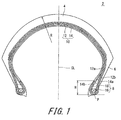
- FIG. 1 illustrates a pneumatic tire 2 manufactured by a manufacturing method according to the present invention.
- the tire 2 is mounted to a two-wheeled automotive vehicle.
- the tire 2 is for front wheels.
- the up-down direction represents the radial direction of the tire 2
- the left-right direction represents the axial direction of the tire 2
- the direction orthogonal to the surface of the drawing sheet represents the circumferential direction of the tire 2.
- an alternate long and short dash line CL represents the equator plane of the tire 2.
- the tire 2 has a shape that is almost bilaterally symmetric with respect to the equator plane.
- the tire 2 includes a tread 4, a pair of sidewalls 6, a pair of beads 8, and a carcass 10.
- the sidewalls 6 extend almost inward from the ends, respectively, of the tread 4 in the radial direction.
- the beads 8 are positioned almost inward of the sidewalls 6, respectively, in the radial direction.
- the carcass 10 is extended between one of the beads 8 and the other of the beads 8 along the inner sides of the tread 4 and the sidewalls 6.
- the tread 4 forms a tread surface that can contact with a road surface.
- the sidewalls 6 absorb impact from the road surface due to their flexure.
- the sidewalls 6 prevent damage to the carcass 10.
- Each bead 8 includes a core 16, and an apex 18 that extends radially outward from the core 16.
- the core 16 is ring-shaped, and includes a non-stretchable wound wire. A typical material of the wire is steel.
- the apex 18 is tapered radially outward.
- the apex 18 is formed of a highly hard crosslinked rubber.
- the carcass 10 includes a first carcass ply 12, and a second carcass ply 14 that is layered outside the first carcass ply 12.
- the first carcass ply 12 is turned up around the beads 8 from the inner side toward the outer side in the axial direction.
- the first carcass ply 12 includes a main portion 12a and turned-up portions 12b.
- the second carcass ply 14 is turned up around the beads 8 from the outer side toward the inner side in the axial direction.
- the second carcass ply 14 By the second carcass ply 14 being turned up, the second carcass ply 14 includes a main portion 14a and turned-up portions 14b.
- the first carcass ply 12 includes a first carcass cord and a topping rubber, which are not shown.
- the first carcass cord is tilted relative to the equator plane.
- An absolute value of an angle of the tilt relative to the equator plane is greater than or equal to 60°, and not greater than 90°.
- the second carcass ply 14 includes a second carcass cord and a topping rubber.
- the second carcass cord is tilted relative to the equator plane.
- An absolute value of an angle of the tilt relative to the equator plane is greater than or equal to 60°, and not greater than 90°.
- the tire 2 is a radial tire.
- first carcass cord and the second carcass cord intersect each other, a direction in which the first carcass cord is tilted and a direction in which the second carcass cord is tilted are opposite to each other with respect to the equator plane.
- the absolute value of the tilt angle of the first carcass cord and the absolute value of the tilt angle of the second carcass cord are equal to each other.
- the first carcass cord and the second carcass cord are each formed from an organic fiber in general.
- the organic fiber include polyester fibers, nylon fibers, rayon fibers, polyethylene naphthalate fibers, and aramid fibers.
- an arrow R represents a radius of curvature of the tread 4 at the equator plane.
- Reference character P represents a radially inner end of the second carcass ply 14 that is turned up around the bead 8.
- a double-headed arrow H represents the height of the turned-up portion 14b of the second carcass ply 14. The height H is measured as a distance, in the radial direction, from the inner end P to the outer end of the turned-up portion 14b.
- the main portion 12a of the first carcass ply 12 is extended from the axially inner side of one of the beads 8 to the axially inner side of the other of the beads 8.
- a tensile force acts on the axially inner sides of the paired beads 8.
- the main portion 14a of the second carcass ply 14 is extended from the axially outer side of one of the beads 8 to the axially outer side of the other of the beads 8.
- a tensile force acts on the axially outer sides of the paired beads 8.
- a tensile force acts on both the axially inner side and the axially outer side of each of the paired beads 8.
- the beads 8 are surrounded by the main portion 12a and the main portion 14a in which the tensile force acts.
- the carcass 10 allows stiffness of the tire 2 to be appropriately improved in a range from the one of the beads 8 to the other of the beads 8.
- the turned-up portions 14b of the second carcass ply 14 are positioned axially inward of the beads 8.
- the second carcass ply 14 is assuredly fixed.
- positional displacement of the second carcass ply 14 is inhibited.
- the turned-up portions 14b being provided, variation in stiffness among the tires 2 is reduced.
- the height H of each turned-up portion 14b of the second carcass ply 14 is preferably greater than or equal to 10 mm and more preferably greater than or equal to 15 mm. Meanwhile, in the tire 2 in which the height H is great to some degree, even when the height H is further increased, further enhancement of an effect of reducing variation in stiffness cannot be expected. In this view point, the height H is preferably not greater than 40 mm.
- the manufacturing method includes a member preparing step, a preforming step, and a vulcanization step.
- the member preparing step members forming the components, of the tire 2, such as the tread 4, the sidewalls 6, the beads 8, and the carcass 10, are prepared.
- the preforming step the members forming the components of the tire 2 are assembled to obtain a raw cover (green tire).
- the vulcanization step the raw cover is placed in a mold. The raw cover is vulcanized and molded in the mold. The tire 2 is obtained from the raw cover.
- a bead carcass member 19 (see FIG. 6(c) ) is prepared.
- the bead carcass member 19 is a member for forming the beads 8 and the carcass 10.
- the member preparing step includes a manufacturing step of manufacturing the bead carcass member 19.
- the manufacturing step of manufacturing the bead carcass member 19 will be described.
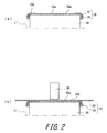
- the manufacturing step includes a ply turning-up step, a ply layering step, and a ply turning-down step.
- a former 20 as a drum is prepared.
- the former 20 has a cylindrical shape.
- the former 20 has an outer circumferential surface 20a.
- an alternate long and short dash line L1 represents the axis of the former 20.
- the diameter of the former 20 can be enlarged and reduced in the radial direction thereof.
- the former 20 can rotate about the axis L1 that acts as a rotation axis.
- the former 20 is rotated.
- a first ply 22 is wound, around the former 20 that is rotating, upon the outer circumferential surface 20a of the former 20.
- the first ply 22 is formed into a cylindrical shape.
- the first ply 22 is a member for forming the first carcass ply 12.
- a main portion 22a of the first ply 22 is wound around the former 20 upon the outer circumferential surface 20a of the former 20.
- An inner circumferential surface of the main portion 22a of the first ply 22 is supported on the outer circumferential surface 20a of the former 20.
- the first ply 22 is wound upon the outer circumferential surface 20a.
- a rubber sheet member may be wound upon the outer circumferential surface 20a.
- the first ply 22 may be cylindrically wound upon the outer circumferential surface of the rubber sheet member.
- End portions 22b, in the axial direction, of the first ply 22 having been cylindrically wound are extended axially outward of the former 20.
- Bead members 24 are disposed on the radially outer sides of the end portions 22b.
- the former 20 includes a pair of end surfaces that extend radially inward from the outer circumferential surface 20a.
- the end surface is a plane that is orthogonal to the axial direction of the former 20.
- the paired bead members 24 are positioned by the end surfaces and are spaced from each other by a predetermined distance in the axial direction.
- the bead members 24 are members for forming the beads 8.
- the end portions 22b are turned up around the bead members 24 from the inner side toward the outer side in the radial direction.
- the end portions 22b having been turned up are layered over the main portion 22a. In this manner, a ply turned-up body 26 that includes the first ply 22 and the bead members 24 is formed.
- turning a ply or the like around each bead member 24 from the inner side toward the outer side in the radial direction is referred to as "turn up”. Meanwhile, turning a ply or the like around each bead member 24 from the outer side toward the inner side in the radial direction is referred to as "turn down”.
- the ply turned-up body 26 is wound around the former 20 upon the outer circumferential surface 20a of the former 20.
- the inner circumferential surface of the ply turned-up body 26 is supported on the outer circumferential surface 20a of the former 20.
- the former 20 is rotated.
- a second ply 28 is wound upon the outer circumferential surface of the ply turned-up body 26.
- the second ply 28 is formed into a cylindrical shape.
- the second ply 28 is a member for forming the second carcass ply 14.
- a stitcher 30 which is rotating, presses the axially center portion of a main portion 28a of the second ply 28 onto the outer circumferential surface of the ply turned-up body 26.
- the stitcher 30 moves in a range from one end of the outer circumferential surface 20a of the former 20 to the other end thereof in the axial direction.
- the second ply 28 is cylindrically layered over the outer circumferential surface of the ply turned-up body 26, to form a ply layered body 32.
- a gap is between the main portion 28a of the second ply 28 and the main portion 22a of the first ply 22.
- the main portion 28a is adhered against the main portion 22a.
- the ply layered body 32 is held by a not-illustrated conveying device.
- the diameter of the former 20 is reduced.
- the ply layered body 32 is moved in the axial direction.
- the ply layered body 32 is removed from the former 20.
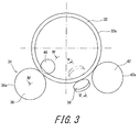
- FIG. 3 illustrates: a part of a ply turning-down machine 34 used in a second-ply turning-down step; and the ply layered body 32.
- the not-illustrated conveying device conveys the ply layered body 32 to the ply turning-down machine 34.
- the ply turning-down machine 34 includes a first roller 36 that serves as a first receiver table, turning-down stitchers 38, layering stitchers 40, and a second roller 42 that serves as a second receiver table.
- the left-right direction represents the front-rear direction of the ply turning-down machine 34.
- the direction perpendicular to the drawing sheet represents the left-right direction of the ply turning-down machine 34.
- the front-rear direction and the left-right direction of the ply turning-down machine 34 are also the horizontal direction.
- the direction perpendicular to the drawing sheet represents the axial direction of the ply layered body 32 placed in the ply turning-down machine 34.
- the first roller 36 has a cylindrical shape.
- the first roller 36 can be rotated about its axis that acts as the rotation axis by a not-illustrated driving device.
- the ply turning-down machine 34 has a pair of left and right turning-down stitchers 38 (see FIG. 5(a) ). Each turning-down stitcher 38 is almost disk-shaped. Each turning-down stitcher 38 is supported so as to be rotatable about its axis that acts as the rotation axis. The turning-down stitchers 38 can be moved around the bead members 24 in the radial direction of the ply layered body 32. In the circumferential direction of the ply layered body 32, the turning-down stitchers 38 are positioned between the first roller 36 and the second roller 42.
- the ply turning-down machine 34 includes a pair of left and right layering stitchers 40 (see FIG. 4(a) ).
- the layering stitchers 40 are almost disk-shaped. Each layering stitcher 40 can be rotated about its axis that acts as the rotation axis.
- the first roller 36 is disposed outward of the layering stitchers 40 in the radial direction.
- the rotation axis of each layering stitcher 40 is parallel to the rotation axis of the first roller 36.
- the layering stitchers 40 can be moved in the radial direction and the axial direction.
- the second roller 42 is positioned in the rear of the first roller 36.
- the second roller 42 and the first roller 36 are spaced from each other in the circumferential direction of the ply layered body 32.
- the second roller 42 has a cylindrical shape.
- the second roller 42 can be rotated about its axis that acts as the rotation axis.
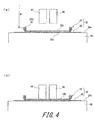
- FIG. 4(a) and FIG. 4(b) show a cross-section taken along a line IV-IV in FIG. 3 .
- an outer circumferential surface 32a of the ply layered body 32 is supported on an outer circumferential surface 36a of the first roller 36.
- the outer circumferential surface 32a of the ply layered body 32 is also supported on an outer circumferential surface 42a of the second roller 42, which is not shown.
- the first roller 36 and the second roller 42 support the ply layered body 32. In this state, the ply layered body 32 can be mounted to or removed from the ply turning-down machine 34.
- the layering stitchers 40 are distant from the ply layered body 32.
- the layering stitchers 40 are in a stand-by orientation in which the layering stitchers 40 are at radially inward positions.
- the layering stitchers 40 in the stand-by orientation are positioned so as not to interfere with the ply layered body 32 when the ply layered body 32 is mounted to or removed from the ply turning-down machine 34.
- a single-headed arrow D represents an inner diameter of the core 16 of the core member 24.
- the inner diameter D of the core 16 is measured at the radially inner end of the core 16.
- the layering stitchers 40 are in contact with an inner circumferential surface 32b of the ply layered body 32.
- the layering stitchers 40 press the ply layered body 32 toward the first roller 36.
- the layering stitchers 40 are in a first pressing orientation.
- the ply layered body 32 is sandwiched between the first roller 36 and the layering stitchers 40.
- the first roller 36 and the layering stitchers 40 support the ply layered body 32.
- the ply layered body 32 sandwiched between the first roller 36 and the layering stitchers 40 is rotated about its axis that acts as the rotation axis.
- the first roller 36 and the layering stitchers 40 rotate the ply layered body 32.
- the first roller 36 rotates clockwise, whereby the ply layered body 32 and the layering stitchers 40 rotate counterclockwise.
- FIG. 5(a) to FIG. 5(c) show a cross-section taken along a line V-V in FIG. 3 .
- the turning-down stitchers 38 are in a stand-by orientation. In the stand-by orientation, the turning-down stitchers 38 are positioned radially outward of the ply layered body 32.
- alternate long and two short dashes lines represent the first roller 36 and the layering stitchers 40 in the cross-section taken along the line IV-IV in FIG. 3 .
- the layering stitchers 40 are in the first pressing orientation. The first roller 36 and the layering stitchers 40 sandwich the ply layered body 32 therebetween.
- the turning-down stitchers 38 are positioned axially outward of the bead members 24. While the outer circumferential surfaces of the turning-down stitchers 38 contact with axial end portions 28b of the second ply 28, each turning-down stitcher 38 rotates about its axis that acts as the rotation axis. The turning-down stitchers 38 turn back the axial end portions 28b of the second ply 28 around the bead members 24. The end portions 28b are turned back from the radially outer side toward the radially inner side.
- the layering stitchers 40 are in the first pressing orientation. The first roller 36 and the layering stitchers 40 sandwich the ply layered body 32 therebetween.
- the turning-down stitchers 38 are positioned axially outward and radially inward of the bead members 24.
- an alternate long and two short dashes line represents the turning-down stitcher 38 in this state. While the outer circumferential surfaces of the turning-down stitchers 38 contact with the axial end portions 28b of the second ply 28, each turning-down stitcher 38 rotates about its axis that acts as the rotation axis. In FIG. 5(c) , the turning-down stitchers 38 further turn back the end portions 28b of the second ply 28, around the bead members 24, from the position shown in FIG. 5(b) .
- the end portions 28b of the second ply 28 are turned back from the axially outer side toward the axially inner side.
- the end portions 28b are turned back toward the radially inner side of the ply layered body 32.
- the layering stitchers 40 are in the first pressing orientation.
- the first roller 36 and the layering stitchers 40 sandwich the ply layered body 32 therebetween.
- FIG. 6(a) to FIG. 6(c) show a cross-section taken along the line IV-IV in FIG. 3 .
- the layering stitchers 40 are in the first pressing orientation.
- the first roller 36 and the layering stitchers 40 sandwich the ply layered body 32 therebetween.
- the end portions 28b of the second ply 28 are turned back toward the radially inner side of the ply layered body 32.
- alternate long and two short dashes lines represent the turning-down stitchers 38 in the cross-section taken along the line V-V in FIG. 3 .
- the turning-down stitchers 38 turn back the end portions 28b of the second ply 28 from the outer side toward the inner side in the axial direction, over the entire circumference of the ply layered body 32.
- the layering stitchers 40 are distant from the ply layered body 32.
- the first roller 36 and the second roller 42 support the outer circumferential surface 32a of the ply layered body 32.
- the layering stitchers 40 are positioned radially inward of the end portions 28b of the second ply 28.
- the layering stitchers 40 are positioned on the radially inner side of the end portions 28b.
- the first roller 36 and the layering stitchers 40 sandwich the end portions 28b of the second ply 28 therebetween.
- the layering stitchers 40 press the end portions 28b onto the first ply 22 of the ply layered body 32.
- the layering stitchers 40 are in a second pressing orientation.
- the turning-down step will be described.
- the not-illustrated conveying device mounts the ply layered body 32 to the ply turning-down machine 34.
- the turning-down stitchers 38 and the layering stitchers 40 are in the stand-by orientation.
- the first roller 36 and the second roller 42 support the ply layered body 32.
- the outer circumferential surface 32a of the ply layered body 32 is supported on the outer circumferential surface 36a of the first roller 36.
- the outer circumferential surface 32a of the ply layered body 32 is supported on the outer circumferential surface 42a of the second roller 42, which is not shown.
- the layering stitchers 40 move toward the outer circumferential surface 36a of the first roller 36.
- the layering stitchers 40 press the ply layered body 32 toward the first roller 36.
- Each layering stitcher 40 shifts its orientation from the stand-by orientation and is in the first pressing orientation.
- the ply layered body 32 is sandwiched between the first roller 36 and the layering stitchers 40.
- the first roller 36 rotates about its axis that acts as the rotation axis. By rotating of the first roller 36, the ply layered body 32 and the layering stitchers 40 rotate about their axes that act as the rotation axes.
- the ply layered body 32 is rotated about its axis that acts as the rotation axis.
- Each turning-down stitcher 38 rotates about its axis that acts as the rotation axis.
- the turning-down stitchers 38 move around the bead members 24 from the radially outer side of the ply layered body 32 toward the radially inner side thereof.
- the turning-down stitchers 38 turn back the end portions 28b of the second ply 28 from the radially outer side of the ply layered body 32 toward the radially inner side thereof.
- the end portions 28b of the second ply 28 are shifted from a position shown in FIG. 5(a) through a position shown in FIG. 5(b) to a position shown in FIG. 5(c) .
- the end portions 28b of the second ply 28 are turned back toward the radially inner side of the ply layered body 32 over the entire circumference.
- the rotation of the first roller 36 is stopped.
- the rotation of the ply layered body 32 is stopped.
- the layering stitchers 40 in the first pressing orientation move radially inward of the ply layered body 32.
- the layering stitchers 40 move toward the axially outer sides of the ply layered body 32.
- the layering stitchers 40 move radially inward of the end portions 28b of the second ply 28. In this manner, the layering stitchers 40 in the first pressing orientation shown in FIG. 6(a) move to positions shown in FIG. 6(b) .
- the layering stitchers 40 move from the positions shown in FIG. 6(b) toward the outer circumferential surface 36a of the first roller 36.
- the first roller 36 and the layering stitchers 40 sandwich the ply layered body 32 therebetween.
- the layering stitchers 40 press the end portions 28b onto the first ply 22 of the ply layered body 32.
- the layering stitchers 40 shift from positions shown in FIG. 6(b) and are in the second pressing orientation shown in FIG. 6(c) .
- the first roller 36 rotates about its axis that acts as the rotation axis. By rotating of the first roller 36, the ply layered body 32 and the layering stitchers 40 rotate. In this manner, the end portions 28b of the second ply 28 are layered over the radially inner side portion of the first ply 22 over the entire circumference.
- the bead carcass member 19 is formed from the ply layered body 32.
- the layering stitchers 40 are returned to the stand-by orientation.
- the not-illustrated conveying device removes the bead carcass member 19 from the ply turning-down machine 34.
- the members including the bead carcass member 19, the tread 4, the sidewalls 6, and the like, which form the components of the tire 2 are assembled to obtain a raw cover (green tire).
- the raw cover is placed in a mold.
- the raw cover is vulcanized and molded at predetermined pressure and temperature. Rubber composition of the members that form the components of the tire 2 is vulcanized.
- the tire 2 is obtained from the raw cover.
- the outer circumferential surface 32a of the ply layered body 32 is supported and the end portions 28b of the second ply 28 are turned down.
- the end portions 28b are easily layered over the radially inner side portion of the first ply 22.
- the turned-up portions 14b of the second carcass ply 14 are layered over the axially inner side portions of the beads 8.
- the ply layered body 32 is rotatably supported. While the ply layered body 32 is rotated, the turning-down stitchers 38 turn the end portions 28b of the second ply 28 down. While the ply layered body 32 is rotated, the layering stitchers 40 operate so as to layer the end portions 28b over the first ply 22. Thus, turning-down and layering of the end portions 28b are easily performed over the entire circumference of the ply layered body 32.
- the first roller 36 supports the outer circumferential surface 32a of the ply layered body 32.
- the first roller 36 and the layering stitchers 40 support the ply layered body 32 such that the ply layered body 32 is rotatable. Further, the first roller 36 and the layering stitchers 40 sandwich the end portions 28b and the first ply 22 therebetween, and rotate the ply layered body 32.
- the layering stitchers 40 operate so as to layer the end portions 28b and rotate the ply layered body 32.
- the layering stitchers 40 are positioned axially inward of the end portions 28b having been turned down.
- the layering stitchers 40 rotate the ply layered body 32 without preventing the end portions 28b from being turned down. Even when the end portions 28b to be turned down are long, the end portions 28b can be turned down.
- the layering stitchers 40 are preferably positioned at the axially center portion of the ply layered body 32.
- the outer circumferential surface 32a of the ply layered body 32 is supported and the end portions 28b of the second ply 28 are turned down.
- the first ply 22 is held over a distance between the paired bead members 24.
- the main portion 28a of the second ply 28 is cylindrically layered over the outer circumference of the main portion 22a of the first ply 22.
- the ply layered body 32 is used, whereby the second ply 28 is layered so as to maintain the distance between the paired bead members 24.
- the first ply 22 is wound around the former 20 upon the outer circumferential surface 20a of the former 20.
- the first ply 22 holds the bead members 24 such that the bead members 24 are accurately spaced by a predetermined distance.
- the second ply 28 is layered over the outer circumferential surface of the ply turned-up body 26 having been wound around the former 20.
- the main portion 28a of the second ply 28 is layered accurately over the outer side portion of the main portion 22a of the first ply 22 without generating looseness and distortion.
- the outer circumferential surface 32a of the ply layered body 32 is supported by the first roller 36 and the second roller 42.
- the first roller 36 and the second roller 42 are spaced from each other in the circumferential direction of the ply layered body 32.
- the center of the rotation of the ply layered body 32 is between the first roller 36 and the second roller 42 in the front-rear direction.
- the ply layered body 32 is stably supported by the ply turning-down machine 34.
- the bead carcass member 19 is stably supported.
- the ply layered body 32 is easily mounted and the bead carcass member 19 is easily removed.
- the conveying device is allowed to easily mount the ply layered body 32 and easily remove the bead carcass member 19.
- a third roller that serves as a third receiver table may be provided in addition to the first roller 36 and the second roller 42.
- the first roller 36, the second roller 42, and the third roller are spaced from each other in the circumferential direction of the ply layered body 32.
- the third roller is disposed above the ply layered body 32 supported by the first roller 36 and the second roller 42, which is not shown.
- the third roller may be pressed onto the outer circumferential surface 32a of the ply layered body 32 by a force which does not deform the ply layered body 32. In this manner, the first roller 36, the second roller 42, and the third roller sandwich the ply layered body 32, whereby the ply layered body 32 is accurately positioned.
- a fourth roller may be provided in addition to the third roller.
- the turning-down stitchers 38 are disposed between the first roller 36 and the second roller 42 in the circumferential direction of the ply layered body 32.
- the end portions 28b of the second ply 28 can be easily turned down.
- the inner diameter D of the core members 24 is preferably less than or equal to 600 mm.
- the layering stitchers 40 can be easily positioned radially inward of the ply layered body 32.
- the inner diameter D is preferably not less than 200 mm, and more preferably not less than 350 mm.
- the raw cover of the tire 2 is vulcanized.
- the raw cover is heated and pressurized.
- the main portion 28a of the second ply 28 is drawn radially outward.
- the end portions 28b of the second ply 28 are extended up to the axially inner side of the bead members 24. Even when a tensile force acts in the main portion 28a, positional displacement of the end portions 28b is inhibited in the second ply 28.
- generation of positional displacement of the second carcass ply 14 is inhibited. For the tire 2, an effect of stably improving stiffness can be obtained.
- a two-wheeled automotive vehicle turns such that the vehicle body is inclined inward.
- the radius R of curvature of the tread 4 is small in the tire 2.
- the radius R of curvature at the equator plane is greater than or equal to 50 mm and not greater than 150 mm in general.
- the radius R of curvature at the equator plane is greater than or equal to 500 mm and not greater than 1000 mm in general.
- a force for drawing toward the center region of the tread 4 acts in the end portions 28b of the second ply 28 around the bead members 24.
- the second ply 28 is turned back around the beads 8.
- the second ply 28 is sandwiched and fixed between the bead members 24 and a cavity surface of the mold. Positional displacement of the end portions 28b of the second ply 28 is inhibited.
- the manufacturing method for manufacturing the tire 2 allows an effect of improving stiffness of the tire 2 to be stably obtained. The quality of the tire 2 is stabilized.
- a load applied to the tire 2 mounted to a two-wheeled automotive vehicle is less than a load applied to a tire mounted to a four-wheeled automotive vehicle. Therefore, the second ply 28 need not be turned back around the cores 16 for assuring stiffness of the tire 2. On the contrary, productivity is reduced by the second ply 28 being turned back around the cores 16.
- the second ply 28 is turned back around the cores 16 purposely to stably obtain an effect of improving stiffness of the tire 2.
- the outer circumferential surface 32a of the ply layered body 32 is supported, and the end portions 28a of the second ply 28 are turned down. For the tire 2, the end portions 28a of the second ply 28 are turned down without increasing reduction of productivity.
- the tire 2 can be manufactured without increasing reduction in productivity of the tire 2.
- the method described above is applicable widely to a tire manufacturing method for manufacturing tires in which the second carcass ply is turned down.
- the method described above is applicable to a manufacturing method for manufacturing tires in which a radius of curvature of the tread is small, for example, for manufacturing tires of two-wheeled automotive vehicles.
Landscapes
- Engineering & Computer Science (AREA)
- Mechanical Engineering (AREA)
- Tyre Moulding (AREA)
- Tires In General (AREA)
Abstract
Description
- This application claims priority on Patent Application No.
2015-185378 - The present invention relates to a tire manufacturing method. Specifically, the present invention relates to a tire manufacturing method for manufacturing a tire in which a carcass is turned down around beads.
-
JP7-68661 - In the tire, a main portion of a first carcass ply is extended on and between the paired beads on the axially inner side. The main portion of the second carcass ply is extended on and between the paired beads on the axially outer side. In the tire, the beads are sandwiched between the main portion of the first carcass ply and the main portion of the second carcass ply in the axial direction. By the first carcass ply and the second carcass ply being provided, stiffness of the tire can be appropriately improved. In the tire, the improvement of stiffness allows improvement of ride comfort and steering stability.
- In the tire manufacturing method disclosed in
JP7-68661 - In the tire vulcanization step, the main portion of the second carcass ply is drawn radially outward around the beads. In the tire, the end portions of the second carcass ply are not extended up to the axially inner sides of the beads, and positional displacement of the end portions of the second carcass ply is likely to occur. This positional displacement may cause variation in stiffness among tires.
- The end portions of the second carcass ply are extended up to the axially inner sides of the beads, whereby the positional displacement of the end portions of the second carcass ply can be reduced. Thus, variation in stiffness among tires can be reduced. However, it is difficult to extend the end portions of the second carcass ply up to the axially inner sides of the beads in the conventional manufacturing method.
- An object of the present invention is to provide a tire manufacturing method for manufacturing a tire in which a carcass ply is turned down.
- A tire manufacturing method according to the present invention includes: a manufacturing step of manufacturing a bead carcass member; a preforming step; and a vulcanization step.
- The manufacturing step of manufacturing the bead carcass member includes:
- a ply turning-up step of turning up axial end portions of a first ply having been cylindrically wound, around bead members from a radially inner side toward a radially outer side, to form a ply turned-up body;
- a ply layering step of layering a second ply over an outer circumferential surface of the ply turned-up body to form a ply layered body; and
- a ply turning-down step of turning down axial end portions of the second ply in the ply layered body, around the bead members from the radially outer side toward the radially inner side, to form the bead carcass member.
- In the ply turning-down step,
the ply layered body is supported at an outer circumferential surface thereof. - While the ply layered body is rotated, the axial end portions of the second ply are turned down around the bead members from the radially outer side toward the radially inner side.
- While the ply layered body is rotated, the axial end portions of the second ply having been turned down to an inner side of the ply layered body are layered over an inner circumferential surface of the ply layered body, to form the bead carcass member.
- In the preforming step, a raw cover including the bead carcass member is formed. In the vulcanization step, the raw cover is placed in a mold, and is vulcanized and molded to obtain a tire.
- Preferably, the first ply is supported on an outer circumferential surface of a drum in the ply turning-up step. The ply turned-up body is supported on the outer circumferential surface of the drum in the ply layering step.
- Preferably, in the ply turning-down step, the outer circumferential surface of the ply layered body is supported by a first receiver table. The axial end portions of the second ply having been turned down to the inner side of the ply layered body are layered over the inner circumferential surface of the ply layered body by a layering stitcher while the ply layered body is rotated. The first receiver table and the layering stitcher rotate the ply layered body.
- Preferably, in the ply turning-down step, the axial end portions of the second ply are turned down around the bead members from the radially outer side toward the radially inner side by a turning-down stitcher while the ply layered body is rotated. When the turning-down stitcher turns down the axial end portions of the second ply from an axially outer side toward an axially inner side, the layering stitcher is positioned axially inward of the axial end portions of the second ply having been turned down.
- Preferably, in the ply turning-down step, the outer circumferential surface of the ply layered body is supported by a second receiver table. The first receiver table and the second receiver table are spaced from each other in a circumferential direction of the ply layered body. A center of rotation of the ply layered body is between the first receiver table and the second receiver table in a horizontal direction.
- Preferably, the turning-down stitcher is positioned between the first receiver table and the second receiver table in the circumferential direction of the ply layered body.
- Preferably, in the ply turning-down step, the outer circumferential surface of the ply layered body is supported by a third receiver table. The first receiver table, the second receiver table, and the third receiver
- table are spaced from each other in the circumferential direction of the ply layered body.
- Preferably, the bead members include cores. Each core has an inner diameter D, and the inner diameter D is less than or equal to 600 mm.
- A manufacturing method for manufacturing a bead carcass member for a tire according to the present invention includes:
- a ply turning-up step of turning up axial end portions of a first ply having been cylindrically wound, around bead members from a radially inner side toward a radially outer side, to form a ply turned-up body;
- a ply layering step of layering a second ply over an outer circumferential surface of the ply turned-up body to form a ply layered body; and
- a ply turning-down step of turning down axial end portions of the second ply in the ply layered body, around the bead members from the radially outer side toward the radially inner side, to form the bead carcass member.
- In the ply turning-down step,
the ply layered body is supported at an outer circumferential surface thereof. - While the ply layered body is rotated, the axial end portions of the second ply are turned down around the bead members from the radially outer side toward the radially inner side.
- While the ply layered body is rotated, the axial end portions of the second ply having been turned down to an inner side of the ply layered body are layered over an inner circumferential surface of the ply layered body, to form the bead carcass member.
- In the manufacturing method for manufacturing the bead carcass member according to the present invention, the axial end portions of the second ply are easily turned down around the bead members. This method allows a carcass ply to be easily turned back around the beads of the tire from the axially outer side toward the axially inner side.
-
-
FIG. 1 is a cross-sectional view of a tire manufactured by a manufacturing method according to one embodiment of the present invention; -
FIG. 2(a) illustrates a first-ply turning-up step of the manufacturing method according to one embodiment of the present invention, andFIG. 2(b) illustrates a second-ply layering step thereof; -
FIG. 3 illustrates a ply turning-down machine used for the manufacturing method according to one embodiment of the present invention; -
FIG. 4(a) illustrates a second-ply turning-down step of the manufacturing method according to one embodiment of the present invention, andFIG. 4(b) illustrates another second-ply turning-down step thereof; -
FIG. 5(a) illustrates still another second-ply turning-down step,FIG. 5(b) illustrates still another second-ply turning-down step, andFIG. 5(c) illustrates still another second-ply turning-down step; and -
FIG. 6(a) illustrates still another second-ply turning-down step,FIG. 6(b) illustrates still another second-ply turning-down step, andFIG. 6(c) illustrates still another second-ply turning-down step. - The following will describe in detail the present invention based on preferred embodiments with reference to the accompanying drawing.
-
FIG. 1 illustrates apneumatic tire 2 manufactured by a manufacturing method according to the present invention. Thetire 2 is mounted to a two-wheeled automotive vehicle. Thetire 2 is for front wheels. InFIG. 1 , the up-down direction represents the radial direction of thetire 2, the left-right direction represents the axial direction of thetire 2, and the direction orthogonal to the surface of the drawing sheet represents the circumferential direction of thetire 2. InFIG. 1 , an alternate long and short dash line CL represents the equator plane of thetire 2. Thetire 2 has a shape that is almost bilaterally symmetric with respect to the equator plane. - The
tire 2 includes atread 4, a pair ofsidewalls 6, a pair of beads 8, and acarcass 10. Thesidewalls 6 extend almost inward from the ends, respectively, of thetread 4 in the radial direction. The beads 8 are positioned almost inward of thesidewalls 6, respectively, in the radial direction. Thecarcass 10 is extended between one of the beads 8 and the other of the beads 8 along the inner sides of thetread 4 and thesidewalls 6. - The
tread 4 forms a tread surface that can contact with a road surface. Thesidewalls 6 absorb impact from the road surface due to their flexure. Thesidewalls 6 prevent damage to thecarcass 10. Each bead 8 includes a core 16, and an apex 18 that extends radially outward from thecore 16. Thecore 16 is ring-shaped, and includes a non-stretchable wound wire. A typical material of the wire is steel. The apex 18 is tapered radially outward. The apex 18 is formed of a highly hard crosslinked rubber. - The
carcass 10 includes afirst carcass ply 12, and a second carcass ply 14 that is layered outside thefirst carcass ply 12. Thefirst carcass ply 12 is turned up around the beads 8 from the inner side toward the outer side in the axial direction. By the first carcass ply 12 being turned up, thefirst carcass ply 12 includes amain portion 12a and turned-upportions 12b. The second carcass ply 14 is turned up around the beads 8 from the outer side toward the inner side in the axial direction. By the second carcass ply 14 being turned up, the second carcass ply 14 includes amain portion 14a and turned-upportions 14b. - The
first carcass ply 12 includes a first carcass cord and a topping rubber, which are not shown. The first carcass cord is tilted relative to the equator plane. An absolute value of an angle of the tilt relative to the equator plane is greater than or equal to 60°, and not greater than 90°. The second carcass ply 14 includes a second carcass cord and a topping rubber. The second carcass cord is tilted relative to the equator plane. An absolute value of an angle of the tilt relative to the equator plane is greater than or equal to 60°, and not greater than 90°. In other words, thetire 2 is a radial tire. In thetire 2 in which the first carcass cord and the second carcass cord intersect each other, a direction in which the first carcass cord is tilted and a direction in which the second carcass cord is tilted are opposite to each other with respect to the equator plane. The absolute value of the tilt angle of the first carcass cord and the absolute value of the tilt angle of the second carcass cord are equal to each other. The first carcass cord and the second carcass cord are each formed from an organic fiber in general. Preferable examples of the organic fiber include polyester fibers, nylon fibers, rayon fibers, polyethylene naphthalate fibers, and aramid fibers. - In
FIG. 1 , an arrow R represents a radius of curvature of thetread 4 at the equator plane. Reference character P represents a radially inner end of the second carcass ply 14 that is turned up around the bead 8. A double-headed arrow H represents the height of the turned-upportion 14b of thesecond carcass ply 14. The height H is measured as a distance, in the radial direction, from the inner end P to the outer end of the turned-upportion 14b. - In the
tire 2, themain portion 12a of thefirst carcass ply 12 is extended from the axially inner side of one of the beads 8 to the axially inner side of the other of the beads 8. In themain portion 12a, a tensile force acts on the axially inner sides of the paired beads 8. Themain portion 14a of the second carcass ply 14 is extended from the axially outer side of one of the beads 8 to the axially outer side of the other of the beads 8. In themain portion 14a, a tensile force acts on the axially outer sides of the paired beads 8. In thecarcass 10, a tensile force acts on both the axially inner side and the axially outer side of each of the paired beads 8. The beads 8 are surrounded by themain portion 12a and themain portion 14a in which the tensile force acts. Thecarcass 10 allows stiffness of thetire 2 to be appropriately improved in a range from the one of the beads 8 to the other of the beads 8. - In the
tire 2, the turned-upportions 14b of the second carcass ply 14 are positioned axially inward of the beads 8. By the turned-upportions 14b, the second carcass ply 14 is assuredly fixed. Also in the vulcanization step of a process in which thetire 2 is manufactured, positional displacement of the second carcass ply 14 is inhibited. By the turned-upportions 14b being provided, variation in stiffness among thetires 2 is reduced. - In view of reducing the variation in stiffness, the height H of each turned-up
portion 14b of the second carcass ply 14 is preferably greater than or equal to 10 mm and more preferably greater than or equal to 15 mm. Meanwhile, in thetire 2 in which the height H is great to some degree, even when the height H is further increased, further enhancement of an effect of reducing variation in stiffness cannot be expected. In this view point, the height H is preferably not greater than 40 mm. - A manufacturing method for manufacturing the
tire 2 will be described. The manufacturing method includes a member preparing step, a preforming step, and a vulcanization step. In the member preparing step, members forming the components, of thetire 2, such as thetread 4, thesidewalls 6, the beads 8, and thecarcass 10, are prepared. In the preforming step, the members forming the components of thetire 2 are assembled to obtain a raw cover (green tire). In the vulcanization step, the raw cover is placed in a mold. The raw cover is vulcanized and molded in the mold. Thetire 2 is obtained from the raw cover. - In the member preparing step, as one of the members forming the components of the
tire 2, a bead carcass member 19 (seeFIG. 6(c) ) is prepared. Thebead carcass member 19 is a member for forming the beads 8 and thecarcass 10. The member preparing step includes a manufacturing step of manufacturing thebead carcass member 19. - The manufacturing step of manufacturing the
bead carcass member 19 will be described. The manufacturing step includes a ply turning-up step, a ply layering step, and a ply turning-down step. - As shown in
FIG. 2(a) , in the ply turning-up step, a former 20 as a drum is prepared. The former 20 has a cylindrical shape. The former 20 has an outercircumferential surface 20a. InFIG. 2(a) , an alternate long and short dash line L1 represents the axis of the former 20. The diameter of the former 20 can be enlarged and reduced in the radial direction thereof. The former 20 can rotate about the axis L1 that acts as a rotation axis. - In the ply turning-up step, the former 20 is rotated. A
first ply 22 is wound, around the former 20 that is rotating, upon the outercircumferential surface 20a of the former 20. Thefirst ply 22 is formed into a cylindrical shape. Thefirst ply 22 is a member for forming thefirst carcass ply 12. Amain portion 22a of thefirst ply 22 is wound around the former 20 upon the outercircumferential surface 20a of the former 20. An inner circumferential surface of themain portion 22a of thefirst ply 22 is supported on the outercircumferential surface 20a of the former 20. In the description herein, thefirst ply 22 is wound upon the outercircumferential surface 20a. A rubber sheet member may be wound upon the outercircumferential surface 20a. Thefirst ply 22 may be cylindrically wound upon the outer circumferential surface of the rubber sheet member. -
End portions 22b, in the axial direction, of thefirst ply 22 having been cylindrically wound are extended axially outward of the former 20.Bead members 24 are disposed on the radially outer sides of theend portions 22b. The former 20 includes a pair of end surfaces that extend radially inward from the outercircumferential surface 20a. The end surface is a plane that is orthogonal to the axial direction of the former 20. The pairedbead members 24 are positioned by the end surfaces and are spaced from each other by a predetermined distance in the axial direction. Thebead members 24 are members for forming the beads 8. Theend portions 22b are turned up around thebead members 24 from the inner side toward the outer side in the radial direction. Theend portions 22b having been turned up are layered over themain portion 22a. In this manner, a ply turned-upbody 26 that includes thefirst ply 22 and thebead members 24 is formed. - In the present invention, turning a ply or the like around each
bead member 24 from the inner side toward the outer side in the radial direction is referred to as "turn up". Meanwhile, turning a ply or the like around eachbead member 24 from the outer side toward the inner side in the radial direction is referred to as "turn down". - As shown in
FIG. 2(b) , in the ply layering step, the ply turned-upbody 26 is wound around the former 20 upon the outercircumferential surface 20a of the former 20. The inner circumferential surface of the ply turned-upbody 26 is supported on the outercircumferential surface 20a of the former 20. The former 20 is rotated. Asecond ply 28 is wound upon the outer circumferential surface of the ply turned-upbody 26. Thesecond ply 28 is formed into a cylindrical shape. Thesecond ply 28 is a member for forming thesecond carcass ply 14. - In the ply layering step, a
stitcher 30 which is rotating, presses the axially center portion of amain portion 28a of thesecond ply 28 onto the outer circumferential surface of the ply turned-upbody 26. Thestitcher 30 moves in a range from one end of the outercircumferential surface 20a of the former 20 to the other end thereof in the axial direction. In this manner, thesecond ply 28 is cylindrically layered over the outer circumferential surface of the ply turned-upbody 26, to form a ply layeredbody 32. InFIG. 2(b) , a gap is between themain portion 28a of thesecond ply 28 and themain portion 22a of thefirst ply 22. However, in the ply layeredbody 32, themain portion 28a is adhered against themain portion 22a. - The ply layered
body 32 is held by a not-illustrated conveying device. The diameter of the former 20 is reduced. The ply layeredbody 32 is moved in the axial direction. The ply layeredbody 32 is removed from the former 20. -
FIG. 3 illustrates: a part of a ply turning-downmachine 34 used in a second-ply turning-down step; and the ply layeredbody 32. The not-illustrated conveying device conveys the ply layeredbody 32 to the ply turning-downmachine 34. The ply turning-downmachine 34 includes afirst roller 36 that serves as a first receiver table, turning-downstitchers 38,layering stitchers 40, and asecond roller 42 that serves as a second receiver table. InFIG. 3 , the left-right direction represents the front-rear direction of the ply turning-downmachine 34. InFIG. 3 , the direction perpendicular to the drawing sheet represents the left-right direction of the ply turning-downmachine 34. The front-rear direction and the left-right direction of the ply turning-downmachine 34 are also the horizontal direction. InFIG. 3 , the direction perpendicular to the drawing sheet represents the axial direction of the ply layeredbody 32 placed in the ply turning-downmachine 34. - The
first roller 36 has a cylindrical shape. Thefirst roller 36 can be rotated about its axis that acts as the rotation axis by a not-illustrated driving device. - The ply turning-down
machine 34 has a pair of left and right turning-down stitchers 38 (seeFIG. 5(a) ). Each turning-downstitcher 38 is almost disk-shaped. Each turning-downstitcher 38 is supported so as to be rotatable about its axis that acts as the rotation axis. The turning-downstitchers 38 can be moved around thebead members 24 in the radial direction of the ply layeredbody 32. In the circumferential direction of the ply layeredbody 32, the turning-downstitchers 38 are positioned between thefirst roller 36 and thesecond roller 42. - The ply turning-down
machine 34 includes a pair of left and right layering stitchers 40 (seeFIG. 4(a) ). The layering stitchers 40 are almost disk-shaped. Eachlayering stitcher 40 can be rotated about its axis that acts as the rotation axis. Thefirst roller 36 is disposed outward of thelayering stitchers 40 in the radial direction. The rotation axis of eachlayering stitcher 40 is parallel to the rotation axis of thefirst roller 36. The layering stitchers 40 can be moved in the radial direction and the axial direction. - The
second roller 42 is positioned in the rear of thefirst roller 36. Thesecond roller 42 and thefirst roller 36 are spaced from each other in the circumferential direction of the ply layeredbody 32. Thesecond roller 42 has a cylindrical shape. Thesecond roller 42 can be rotated about its axis that acts as the rotation axis. -
FIG. 4(a) and FIG. 4(b) show a cross-section taken along a line IV-IV inFIG. 3 . InFIG. 4(a) , an outercircumferential surface 32a of the ply layeredbody 32 is supported on an outercircumferential surface 36a of thefirst roller 36. The outercircumferential surface 32a of the ply layeredbody 32 is also supported on an outercircumferential surface 42a of thesecond roller 42, which is not shown. InFIG. 4(a) , thefirst roller 36 and thesecond roller 42 support the ply layeredbody 32. In this state, the ply layeredbody 32 can be mounted to or removed from the ply turning-downmachine 34. - In
FIG. 4(a) , thelayering stitchers 40 are distant from the ply layeredbody 32. The layering stitchers 40 are in a stand-by orientation in which thelayering stitchers 40 are at radially inward positions. The layering stitchers 40 in the stand-by orientation are positioned so as not to interfere with the ply layeredbody 32 when the ply layeredbody 32 is mounted to or removed from the ply turning-downmachine 34. - In
FIG. 4(a) , a single-headed arrow D represents an inner diameter of thecore 16 of thecore member 24. The inner diameter D of thecore 16 is measured at the radially inner end of thecore 16. - In
FIG. 4(b) , thelayering stitchers 40 are in contact with an innercircumferential surface 32b of the ply layeredbody 32. The layering stitchers 40 press the ply layeredbody 32 toward thefirst roller 36. The layering stitchers 40 are in a first pressing orientation. The ply layeredbody 32 is sandwiched between thefirst roller 36 and thelayering stitchers 40. Thefirst roller 36 and thelayering stitchers 40 support the ply layeredbody 32. By rotating of thefirst roller 36, the ply layeredbody 32 sandwiched between thefirst roller 36 and thelayering stitchers 40 is rotated about its axis that acts as the rotation axis. Thefirst roller 36 and thelayering stitchers 40 rotate the ply layeredbody 32. For example, inFIG. 3 , thefirst roller 36 rotates clockwise, whereby the ply layeredbody 32 and thelayering stitchers 40 rotate counterclockwise. -
FIG. 5(a) to FIG. 5(c) show a cross-section taken along a line V-V inFIG. 3 . InFIG. 5(a) , the turning-downstitchers 38 are in a stand-by orientation. In the stand-by orientation, the turning-downstitchers 38 are positioned radially outward of the ply layeredbody 32. InFIG. 5(a) , alternate long and two short dashes lines represent thefirst roller 36 and thelayering stitchers 40 in the cross-section taken along the line IV-IV inFIG. 3 . InFIG. 5(a) , thelayering stitchers 40 are in the first pressing orientation. Thefirst roller 36 and thelayering stitchers 40 sandwich the ply layeredbody 32 therebetween. - In
FIG. 5(b) , the turning-downstitchers 38 are positioned axially outward of thebead members 24. While the outer circumferential surfaces of the turning-downstitchers 38 contact withaxial end portions 28b of thesecond ply 28, each turning-downstitcher 38 rotates about its axis that acts as the rotation axis. The turning-downstitchers 38 turn back theaxial end portions 28b of thesecond ply 28 around thebead members 24. Theend portions 28b are turned back from the radially outer side toward the radially inner side. InFIG. 5(b) , thelayering stitchers 40 are in the first pressing orientation. Thefirst roller 36 and thelayering stitchers 40 sandwich the ply layeredbody 32 therebetween. - In
FIG. 5(c) , the turning-downstitchers 38 are positioned axially outward and radially inward of thebead members 24. InFIG. 3 , an alternate long and two short dashes line represents the turning-downstitcher 38 in this state. While the outer circumferential surfaces of the turning-downstitchers 38 contact with theaxial end portions 28b of thesecond ply 28, each turning-downstitcher 38 rotates about its axis that acts as the rotation axis. InFIG. 5(c) , the turning-downstitchers 38 further turn back theend portions 28b of thesecond ply 28, around thebead members 24, from the position shown inFIG. 5(b) . Theend portions 28b of thesecond ply 28 are turned back from the axially outer side toward the axially inner side. Theend portions 28b are turned back toward the radially inner side of the ply layeredbody 32. InFIG. 5(c) , thelayering stitchers 40 are in the first pressing orientation. Thefirst roller 36 and thelayering stitchers 40 sandwich the ply layeredbody 32 therebetween. -
FIG. 6(a) to FIG. 6(c) show a cross-section taken along the line IV-IV inFIG. 3 . InFIG. 6(a) , thelayering stitchers 40 are in the first pressing orientation. Thefirst roller 36 and thelayering stitchers 40 sandwich the ply layeredbody 32 therebetween. InFIG. 6(a) , theend portions 28b of thesecond ply 28 are turned back toward the radially inner side of the ply layeredbody 32. InFIG. 6(a) , alternate long and two short dashes lines represent the turning-downstitchers 38 in the cross-section taken along the line V-V inFIG. 3 . InFIG. 6(a) , the turning-downstitchers 38 turn back theend portions 28b of thesecond ply 28 from the outer side toward the inner side in the axial direction, over the entire circumference of the ply layeredbody 32. - In
FIG. 6(b) , thelayering stitchers 40 are distant from the ply layeredbody 32. Thefirst roller 36 and thesecond roller 42 support the outercircumferential surface 32a of the ply layeredbody 32. The layering stitchers 40 are positioned radially inward of theend portions 28b of thesecond ply 28. - In
FIG. 6(c) , thelayering stitchers 40 are positioned on the radially inner side of theend portions 28b. Thefirst roller 36 and thelayering stitchers 40 sandwich theend portions 28b of thesecond ply 28 therebetween. The layering stitchers 40 press theend portions 28b onto thefirst ply 22 of the ply layeredbody 32. InFIG. 6(c) , thelayering stitchers 40 are in a second pressing orientation. - With reference to
FIG. 3 to FIG. 6 , the turning-down step will be described. In the turning-down step, the not-illustrated conveying device mounts the ply layeredbody 32 to the ply turning-downmachine 34. At this time, the turning-downstitchers 38 and thelayering stitchers 40 are in the stand-by orientation. In the ply turning-downmachine 34, thefirst roller 36 and thesecond roller 42 support the ply layeredbody 32. As shown inFIG. 4(a) , the outercircumferential surface 32a of the ply layeredbody 32 is supported on the outercircumferential surface 36a of thefirst roller 36. The outercircumferential surface 32a of the ply layeredbody 32 is supported on the outercircumferential surface 42a of thesecond roller 42, which is not shown. - As shown in
FIG. 4(b) , thelayering stitchers 40 move toward the outercircumferential surface 36a of thefirst roller 36. The layering stitchers 40 press the ply layeredbody 32 toward thefirst roller 36. Eachlayering stitcher 40 shifts its orientation from the stand-by orientation and is in the first pressing orientation. The ply layeredbody 32 is sandwiched between thefirst roller 36 and thelayering stitchers 40. Thefirst roller 36 rotates about its axis that acts as the rotation axis. By rotating of thefirst roller 36, the ply layeredbody 32 and thelayering stitchers 40 rotate about their axes that act as the rotation axes. - In
FIG. 5(a), FIG. 5(b), and FIG. 5(c) , the ply layeredbody 32 is rotated about its axis that acts as the rotation axis. Each turning-downstitcher 38 rotates about its axis that acts as the rotation axis. The turning-downstitchers 38 move around thebead members 24 from the radially outer side of the ply layeredbody 32 toward the radially inner side thereof. The turning-downstitchers 38 turn back theend portions 28b of thesecond ply 28 from the radially outer side of the ply layeredbody 32 toward the radially inner side thereof. In the ply layeredbody 32, theend portions 28b of thesecond ply 28 are shifted from a position shown inFIG. 5(a) through a position shown inFIG. 5(b) to a position shown inFIG. 5(c) . - In
FIG. 6(a) , theend portions 28b of thesecond ply 28 are turned back toward the radially inner side of the ply layeredbody 32 over the entire circumference. The rotation of thefirst roller 36 is stopped. The rotation of the ply layeredbody 32 is stopped. The layering stitchers 40 in the first pressing orientation move radially inward of the ply layeredbody 32. Further, thelayering stitchers 40 move toward the axially outer sides of the ply layeredbody 32. The layering stitchers 40 move radially inward of theend portions 28b of thesecond ply 28. In this manner, thelayering stitchers 40 in the first pressing orientation shown inFIG. 6(a) move to positions shown inFIG. 6(b) . - The layering stitchers 40 move from the positions shown in
FIG. 6(b) toward the outercircumferential surface 36a of thefirst roller 36. Thefirst roller 36 and thelayering stitchers 40 sandwich the ply layeredbody 32 therebetween. The layering stitchers 40 press theend portions 28b onto thefirst ply 22 of the ply layeredbody 32. The layering stitchers 40 shift from positions shown inFIG. 6(b) and are in the second pressing orientation shown inFIG. 6(c) . Thefirst roller 36 rotates about its axis that acts as the rotation axis. By rotating of thefirst roller 36, the ply layeredbody 32 and thelayering stitchers 40 rotate. In this manner, theend portions 28b of thesecond ply 28 are layered over the radially inner side portion of thefirst ply 22 over the entire circumference. - In this manner, the
bead carcass member 19 is formed from the ply layeredbody 32. The layering stitchers 40 are returned to the stand-by orientation. The not-illustrated conveying device removes thebead carcass member 19 from the ply turning-downmachine 34. - In the preforming step, the members, including the
bead carcass member 19, thetread 4, thesidewalls 6, and the like, which form the components of thetire 2 are assembled to obtain a raw cover (green tire). - In the vulcanization step, the raw cover is placed in a mold. The raw cover is vulcanized and molded at predetermined pressure and temperature. Rubber composition of the members that form the components of the
tire 2 is vulcanized. Thetire 2 is obtained from the raw cover. - In the ply turning-down step of the manufacturing method, the outer
circumferential surface 32a of the ply layeredbody 32 is supported and theend portions 28b of thesecond ply 28 are turned down. In this method, theend portions 28b are easily layered over the radially inner side portion of thefirst ply 22. Thus, in thetire 2, the turned-upportions 14b of the second carcass ply 14 are layered over the axially inner side portions of the beads 8. - In the ply turning-down step, the ply layered
body 32 is rotatably supported. While the ply layeredbody 32 is rotated, the turning-downstitchers 38 turn theend portions 28b of thesecond ply 28 down. While the ply layeredbody 32 is rotated, thelayering stitchers 40 operate so as to layer theend portions 28b over thefirst ply 22. Thus, turning-down and layering of theend portions 28b are easily performed over the entire circumference of the ply layeredbody 32. - In the ply turning-down step, the
first roller 36 supports the outercircumferential surface 32a of the ply layeredbody 32. Thefirst roller 36 and thelayering stitchers 40 support the ply layeredbody 32 such that the ply layeredbody 32 is rotatable. Further, thefirst roller 36 and thelayering stitchers 40 sandwich theend portions 28b and thefirst ply 22 therebetween, and rotate the ply layeredbody 32. The layering stitchers 40 operate so as to layer theend portions 28b and rotate the ply layeredbody 32. - In the ply turning-down step, when the turning-down
stitchers 38 turn down theend portions 28b of thesecond ply 28 from the axially outer side toward the axially inner side, thelayering stitchers 40 are positioned axially inward of theend portions 28b having been turned down. The layering stitchers 40 rotate the ply layeredbody 32 without preventing theend portions 28b from being turned down. Even when theend portions 28b to be turned down are long, theend portions 28b can be turned down. In this viewpoint, thelayering stitchers 40 are preferably positioned at the axially center portion of the ply layeredbody 32. - In the ply turning-down step, the outer
circumferential surface 32a of the ply layeredbody 32 is supported and theend portions 28b of thesecond ply 28 are turned down. In the ply layeredbody 32, thefirst ply 22 is held over a distance between the pairedbead members 24. In the ply layeredbody 32, themain portion 28a of thesecond ply 28 is cylindrically layered over the outer circumference of themain portion 22a of thefirst ply 22. The ply layeredbody 32 is used, whereby thesecond ply 28 is layered so as to maintain the distance between the pairedbead members 24. - In the ply turning-up step, the
first ply 22 is wound around the former 20 upon the outercircumferential surface 20a of the former 20. Thus, in the ply layeredbody 32, thefirst ply 22 holds thebead members 24 such that thebead members 24 are accurately spaced by a predetermined distance. In the ply layering step, thesecond ply 28 is layered over the outer circumferential surface of the ply turned-upbody 26 having been wound around the former 20. Thus, in the ply layeredbody 32, themain portion 28a of thesecond ply 28 is layered accurately over the outer side portion of themain portion 22a of thefirst ply 22 without generating looseness and distortion. - In the ply turning-down step, the outer
circumferential surface 32a of the ply layeredbody 32 is supported by thefirst roller 36 and thesecond roller 42. Thefirst roller 36 and thesecond roller 42 are spaced from each other in the circumferential direction of the ply layeredbody 32. The center of the rotation of the ply layeredbody 32 is between thefirst roller 36 and thesecond roller 42 in the front-rear direction. Thus, the ply layeredbody 32 is stably supported by the ply turning-downmachine 34. Thebead carcass member 19 is stably supported. Thus, in the ply turning-downmachine 34, the ply layeredbody 32 is easily mounted and thebead carcass member 19 is easily removed. The conveying device is allowed to easily mount the ply layeredbody 32 and easily remove thebead carcass member 19. - In the turning-down step, in order to stably support the outer
circumferential surface 32a of the ply layeredbody 32, a third roller that serves as a third receiver table may be provided in addition to thefirst roller 36 and thesecond roller 42. Thefirst roller 36, thesecond roller 42, and the third roller are spaced from each other in the circumferential direction of the ply layeredbody 32. For example, the third roller is disposed above the ply layeredbody 32 supported by thefirst roller 36 and thesecond roller 42, which is not shown. The third roller may be pressed onto the outercircumferential surface 32a of the ply layeredbody 32 by a force which does not deform the ply layeredbody 32. In this manner, thefirst roller 36, thesecond roller 42, and the third roller sandwich the ply layeredbody 32, whereby the ply layeredbody 32 is accurately positioned. Further, a fourth roller may be provided in addition to the third roller. - In the turning-down step, the turning-down
stitchers 38 are disposed between thefirst roller 36 and thesecond roller 42 in the circumferential direction of the ply layeredbody 32. Thus, theend portions 28b of thesecond ply 28 can be easily turned down. - In the turning-down step, when an inner diameter D of the
core members 24 is small, the ply layeredbody 32 is stably supported by the outercircumferential surface 32a being supported. In this viewpoint, the inner diameter D of thecore members 24 is preferably less than or equal to 600 mm. Meanwhile, when the inner diameter D of thecore members 24 is large in the ply layeredbody 32, thelayering stitchers 40 can be easily positioned radially inward of the ply layeredbody 32. In this viewpoint, the inner diameter D is preferably not less than 200 mm, and more preferably not less than 350 mm. - In the vulcanization step, the raw cover of the
tire 2 is vulcanized. In the vulcanization step, the raw cover is heated and pressurized. By the raw cover being heated and pressurized, themain portion 28a of thesecond ply 28 is drawn radially outward. In thebead carcass member 19, theend portions 28b of thesecond ply 28 are extended up to the axially inner side of thebead members 24. Even when a tensile force acts in themain portion 28a, positional displacement of theend portions 28b is inhibited in thesecond ply 28. In thetire 2, generation of positional displacement of the second carcass ply 14 is inhibited. For thetire 2, an effect of stably improving stiffness can be obtained. - A two-wheeled automotive vehicle turns such that the vehicle body is inclined inward. In order to facilitate the turning, the radius R of curvature of the
tread 4 is small in thetire 2. When the vehicle runs straight with thetire 2, a center region positioned at the axially center of thetread 4 contacts with the ground, and when the vehicle turns with thetire 2, a shoulder region positioned on the axially outer side of thetread 4 contacts with the ground. In thetire 2 mounted to a two-wheeled automotive vehicle, the radius R of curvature at the equator plane is greater than or equal to 50 mm and not greater than 150 mm in general. Meanwhile, in a tire mounted to a four-wheeled automotive vehicle, the radius R of curvature at the equator plane is greater than or equal to 500 mm and not greater than 1000 mm in general. - In the vulcanization step, in a raw cover of the
tire 2 in which the radius R of curvature is small, a force for drawing toward the center region of thetread 4 acts in theend portions 28b of thesecond ply 28 around thebead members 24. In thetire 2, thesecond ply 28 is turned back around the beads 8. Thesecond ply 28 is sandwiched and fixed between thebead members 24 and a cavity surface of the mold. Positional displacement of theend portions 28b of thesecond ply 28 is inhibited. The manufacturing method for manufacturing thetire 2 allows an effect of improving stiffness of thetire 2 to be stably obtained. The quality of thetire 2 is stabilized. - A load applied to the
tire 2 mounted to a two-wheeled automotive vehicle is less than a load applied to a tire mounted to a four-wheeled automotive vehicle. Therefore, thesecond ply 28 need not be turned back around thecores 16 for assuring stiffness of thetire 2. On the contrary, productivity is reduced by thesecond ply 28 being turned back around thecores 16. Thesecond ply 28 is turned back around thecores 16 purposely to stably obtain an effect of improving stiffness of thetire 2. In the present invention, the outercircumferential surface 32a of the ply layeredbody 32 is supported, and theend portions 28a of thesecond ply 28 are turned down. For thetire 2, theend portions 28a of thesecond ply 28 are turned down without increasing reduction of productivity. In the present invention, thetire 2 can be manufactured without increasing reduction in productivity of thetire 2. - The method described above is applicable widely to a tire manufacturing method for manufacturing tires in which the second carcass ply is turned down. In particular, the method described above is applicable to a manufacturing method for manufacturing tires in which a radius of curvature of the tread is small, for example, for manufacturing tires of two-wheeled automotive vehicles.
- The foregoing description is in all aspects illustrative, and various modifications can be devised without departing from the essential features of the invention.
Claims (9)
- A tire manufacturing method comprising:a manufacturing step of manufacturing a bead carcass member;a preforming step; anda vulcanization step, whereinthe manufacturing step of manufacturing the bead carcass member includes:a ply turning-up step of turning up axial end portions of a first ply having been cylindrically wound, around bead members from a radially inner side toward a radially outer side, to form a ply turned-up body;a ply layering step of layering a second ply over an outer circumferential surface of the ply turned-up body to form a ply layered body; anda ply turning-down step of turning down axial end portions of the second ply in the ply layered body, around the bead members from the radially outer side toward the radially inner side, to form the bead carcass member,in the ply turning-down step,
the ply layered body is supported at an outer circumferential surface thereof,
while the ply layered body is rotated, the axial end portions of the second ply are turned down around the bead members from the radially outer side toward the radially inner side, and
while the ply layered body is rotated, the axial end portions of the second ply having been turned down to an inner side of the ply layered body are layered over an inner circumferential surface of the ply layered body, to form the bead carcass member,
in the preforming step, a raw cover including the bead carcass member is formed, and
in the vulcanization step, the raw cover is placed in a mold, and is vulcanized and molded to obtain a tire. - The manufacturing method according to claim 1, wherein
the first ply is supported on an outer circumferential surface of a drum in the ply turning-up step, and
the ply turned-up body is supported on the outer circumferential surface of the drum in the ply layering step. - The manufacturing method according to claim 1, wherein in the ply turning-down step,
the outer circumferential surface of the ply layered body is supported by a first receiver table,
the axial end portions of the second ply having been turned down to the inner side of the ply layered body are layered over the inner circumferential surface of the ply layered body by a layering stitcher while the ply layered body is rotated, and
the first receiver table and the layering stitcher rotate the ply layered body. - The manufacturing method according to claim 3, wherein in the ply turning-down step,
the axial end portions of the second ply are turned down around the bead members from the radially outer side toward the radially inner side by a turning-down stitcher while the ply layered body is rotated, and
when the turning-down stitcher turns down the axial end portions of the second ply from an axially outer side toward an axially inner side, the layering stitcher is positioned axially inward of the axial end portions of the second ply having been turned down. - The manufacturing method according to claim 3, wherein in the ply turning-down step,
the outer circumferential surface of the ply layered body is supported by a second receiver table,
the first receiver table and the second receiver table are spaced from each other in a circumferential direction of the ply layered body, and
a center of rotation of the ply layered body is between the first receiver table and the second receiver table in a horizontal direction. - The manufacturing method according to claim 5, wherein the turning-down stitcher is positioned between the first receiver table and the second receiver table in the circumferential direction of the ply layered body.
- The manufacturing method according to claim 5, wherein in the ply turning-down step,
the outer circumferential surface of the ply layered body is supported by a third receiver table, and
the first receiver table, the second receiver table, and the third receiver table are spaced from each other in the circumferential direction of the ply layered body. - The manufacturing method according to claim 1, wherein
the bead members include cores, and
each core has an inner diameter D, and the inner diameter D is less than or equal to 600 mm. - A manufacturing method for manufacturing a bead carcass member for a tire, the manufacturing method comprising:a ply turning-up step of turning up axial end portions of a first ply having been cylindrically wound, around bead members from a radially inner side toward a radially outer side, to form a ply turned-up body;a ply layering step of layering a second ply over an outer circumferential surface of the ply turned-up body to form a ply layered body; anda ply turning-down step of turning down axial end portions of the second ply in the ply layered body, around the bead members from the radially outer side toward the radially inner side, to form the bead carcass member,in the ply turning-down step,
the ply layered body is supported at an outer circumferential surface thereof,
while the ply layered body is rotated, the axial end portions of the second ply are turned down around the bead members from the radially outer side toward the radially inner side, and
while the ply layered body is rotated, the axial end portions of the second ply having been turned down to an inner side of the ply layered body are layered over an inner circumferential surface of the ply layered body, to form the bead carcass member.
Applications Claiming Priority (1)
| Application Number | Priority Date | Filing Date | Title |
|---|---|---|---|
| JP2015185378A JP2017056680A (en) | 2015-09-18 | 2015-09-18 | Method for manufacturing tire |
Publications (1)
| Publication Number | Publication Date |
|---|---|
| EP3144131A1 true EP3144131A1 (en) | 2017-03-22 |
Family
ID=56615913
Family Applications (1)
| Application Number | Title | Priority Date | Filing Date |
|---|---|---|---|
| EP16183373.6A Withdrawn EP3144131A1 (en) | 2015-09-18 | 2016-08-09 | Tire manufacturing method |
Country Status (4)
| Country | Link |
|---|---|
| US (1) | US20170080658A1 (en) |
| EP (1) | EP3144131A1 (en) |
| JP (1) | JP2017056680A (en) |
| CN (1) | CN106541594A (en) |
Cited By (1)
| Publication number | Priority date | Publication date | Assignee | Title |
|---|---|---|---|---|
| EP3753722B1 (en) * | 2018-02-16 | 2024-10-09 | The Yokohama Rubber Co., Ltd. | Method for manufacturing tire |
Families Citing this family (1)
| Publication number | Priority date | Publication date | Assignee | Title |
|---|---|---|---|---|
| NL2029249B1 (en) * | 2021-09-24 | 2023-03-30 | Vmi Holland Bv | Stitcher, tire building machine comprising said stitcher and method for stitching a tire component |
Citations (6)
| Publication number | Priority date | Publication date | Assignee | Title |
|---|---|---|---|---|
| GB448501A (en) * | 1934-11-09 | 1936-06-09 | Dunlop Rubber Co | Improvements in or relating to the building-up of pneumatic tyre covers |
| US2259162A (en) * | 1937-11-04 | 1941-10-14 | Us Rubber Co | Apparatus for manufacturing tires |
| US2409974A (en) * | 1942-08-06 | 1946-10-22 | Gen Tire & Rubber Co | Tire building machine |
| US3032093A (en) * | 1957-03-21 | 1962-05-01 | Dunlop Rubber Co | Tire manufacture apparatus |
| JPH0768661A (en) | 1993-09-03 | 1995-03-14 | Sumitomo Rubber Ind Ltd | Tire molding method |
| WO2014103110A1 (en) * | 2012-12-26 | 2014-07-03 | 東洋ゴム工業株式会社 | Pneumatic tire and method for manufacturing same |
Family Cites Families (5)
| Publication number | Priority date | Publication date | Assignee | Title |
|---|---|---|---|---|
| US1664259A (en) * | 1926-05-10 | 1928-03-27 | Fisk Rubber Co | Method of building tire casings |
| GB479092A (en) * | 1935-08-05 | 1938-01-31 | Wingfoot Corp | Improvements relating to method and apparatus for building tires |
| JPH07117151A (en) * | 1993-10-21 | 1995-05-09 | Toyo Tire & Rubber Co Ltd | Molding of radial tire |
| DE69706212T2 (en) * | 1996-03-26 | 2002-01-10 | Sumitomo Rubber Industries Ltd., Kobe | tire |
| EP1625931B1 (en) * | 2003-05-20 | 2008-09-24 | The Yokohama Rubber Co., Ltd. | Method of producing pneumatic radial tire |
-
2015
- 2015-09-18 JP JP2015185378A patent/JP2017056680A/en active Pending
-
2016
- 2016-05-20 CN CN201610341458.2A patent/CN106541594A/en active Pending
- 2016-08-09 EP EP16183373.6A patent/EP3144131A1/en not_active Withdrawn
- 2016-08-22 US US15/243,102 patent/US20170080658A1/en not_active Abandoned
Patent Citations (6)
| Publication number | Priority date | Publication date | Assignee | Title |
|---|---|---|---|---|
| GB448501A (en) * | 1934-11-09 | 1936-06-09 | Dunlop Rubber Co | Improvements in or relating to the building-up of pneumatic tyre covers |
| US2259162A (en) * | 1937-11-04 | 1941-10-14 | Us Rubber Co | Apparatus for manufacturing tires |
| US2409974A (en) * | 1942-08-06 | 1946-10-22 | Gen Tire & Rubber Co | Tire building machine |
| US3032093A (en) * | 1957-03-21 | 1962-05-01 | Dunlop Rubber Co | Tire manufacture apparatus |
| JPH0768661A (en) | 1993-09-03 | 1995-03-14 | Sumitomo Rubber Ind Ltd | Tire molding method |
| WO2014103110A1 (en) * | 2012-12-26 | 2014-07-03 | 東洋ゴム工業株式会社 | Pneumatic tire and method for manufacturing same |
Cited By (1)
| Publication number | Priority date | Publication date | Assignee | Title |
|---|---|---|---|---|
| EP3753722B1 (en) * | 2018-02-16 | 2024-10-09 | The Yokohama Rubber Co., Ltd. | Method for manufacturing tire |
Also Published As
| Publication number | Publication date |
|---|---|
| CN106541594A (en) | 2017-03-29 |
| US20170080658A1 (en) | 2017-03-23 |
| JP2017056680A (en) | 2017-03-23 |
Similar Documents
| Publication | Publication Date | Title |
|---|---|---|
| EP3225427B1 (en) | Pneumatic tire and method for manufacturing pneumatic tire | |
| US20150013863A1 (en) | Tire With Pre-Formed Tread And Method Of Making Same | |
| US7361243B2 (en) | Tire manufacturing method and green tire manufacturing apparatus | |
| EP3192672A1 (en) | Pneumatic tire | |
| US11383560B2 (en) | Tire for two-wheeled automotive vehicle | |
| EP3530485B1 (en) | Pneumatic tire | |
| US20170080658A1 (en) | Tire manufacturing method | |
| EP3202599B1 (en) | Pneumatic tire | |
| EP3189979B1 (en) | Pneumatic tire | |
| CN103158441A (en) | Pneumatic tire and its manufacturing method | |
| EP2561980B1 (en) | Tire production method | |
| EP2492115B1 (en) | Radial tire for use in two-wheeled vehicle | |
| EP3366492B1 (en) | Pneumatic tire for two-wheeled automotive vehicle | |
| JP6193626B2 (en) | Pneumatic tire | |
| EP4282666B1 (en) | Tire | |
| JP5798319B2 (en) | Method for forming cylindrical green tire | |
| JP4995520B2 (en) | Pneumatic tire | |
| JP4813070B2 (en) | Pneumatic tires for motorcycles | |
| EP3228476B1 (en) | Pneumatic tire | |
| JP2024010614A (en) | Tire manufacturing method | |
| JP6298351B2 (en) | Pneumatic tire assembly | |
| JP2014144544A (en) | Tire manufacturing method |
Legal Events
| Date | Code | Title | Description |
|---|---|---|---|
| PUAI | Public reference made under article 153(3) epc to a published international application that has entered the european phase |
Free format text: ORIGINAL CODE: 0009012 |
|
| STAA | Information on the status of an ep patent application or granted ep patent |
Free format text: STATUS: THE APPLICATION HAS BEEN PUBLISHED |
|
| AK | Designated contracting states |
Kind code of ref document: A1 Designated state(s): AL AT BE BG CH CY CZ DE DK EE ES FI FR GB GR HR HU IE IS IT LI LT LU LV MC MK MT NL NO PL PT RO RS SE SI SK SM TR |
|
| AX | Request for extension of the european patent |
Extension state: BA ME |
|
| STAA | Information on the status of an ep patent application or granted ep patent |
Free format text: STATUS: REQUEST FOR EXAMINATION WAS MADE |
|
| 17P | Request for examination filed |
Effective date: 20170911 |
|
| RBV | Designated contracting states (corrected) |
Designated state(s): AL AT BE BG CH CY CZ DE DK EE ES FI FR GB GR HR HU IE IS IT LI LT LU LV MC MK MT NL NO PL PT RO RS SE SI SK SM TR |
|
| GRAP | Despatch of communication of intention to grant a patent |
Free format text: ORIGINAL CODE: EPIDOSNIGR1 |
|
| STAA | Information on the status of an ep patent application or granted ep patent |
Free format text: STATUS: GRANT OF PATENT IS INTENDED |
|
| RIC1 | Information provided on ipc code assigned before grant |
Ipc: B60C 15/04 20060101ALI20181001BHEP Ipc: B29D 30/16 20060101ALI20181001BHEP Ipc: B29D 30/06 20060101ALI20181001BHEP Ipc: B60C 15/00 20060101ALI20181001BHEP Ipc: B29D 30/34 20060101ALI20181001BHEP Ipc: B29D 30/32 20060101AFI20181001BHEP |
|
| INTG | Intention to grant announced |
Effective date: 20181025 |
|
| STAA | Information on the status of an ep patent application or granted ep patent |
Free format text: STATUS: THE APPLICATION IS DEEMED TO BE WITHDRAWN |
|
| 18D | Application deemed to be withdrawn |
Effective date: 20190305 |