EP3144091B1 - Rotating replacement device for welding torch - Google Patents
Rotating replacement device for welding torch Download PDFInfo
- Publication number
- EP3144091B1 EP3144091B1 EP16794915.5A EP16794915A EP3144091B1 EP 3144091 B1 EP3144091 B1 EP 3144091B1 EP 16794915 A EP16794915 A EP 16794915A EP 3144091 B1 EP3144091 B1 EP 3144091B1
- Authority
- EP
- European Patent Office
- Prior art keywords
- rotator
- rotational axis
- torch
- nozzle
- interlocking
- Prior art date
- Legal status (The legal status is an assumption and is not a legal conclusion. Google has not performed a legal analysis and makes no representation as to the accuracy of the status listed.)
- Active
Links
- 238000003466 welding Methods 0.000 title claims description 61
- 230000002093 peripheral effect Effects 0.000 claims description 51
- 229920001971 elastomer Polymers 0.000 description 9
- 239000005060 rubber Substances 0.000 description 9
- 230000007246 mechanism Effects 0.000 description 7
- 230000007423 decrease Effects 0.000 description 5
- 230000003247 decreasing effect Effects 0.000 description 4
- 238000003780 insertion Methods 0.000 description 4
- 230000037431 insertion Effects 0.000 description 4
- 238000000034 method Methods 0.000 description 4
- 229910000831 Steel Inorganic materials 0.000 description 3
- 238000003825 pressing Methods 0.000 description 3
- 239000010959 steel Substances 0.000 description 3
- 238000004891 communication Methods 0.000 description 2
- 230000008878 coupling Effects 0.000 description 2
- 238000010168 coupling process Methods 0.000 description 2
- 238000005859 coupling reaction Methods 0.000 description 2
- 238000004519 manufacturing process Methods 0.000 description 2
- 229920002379 silicone rubber Polymers 0.000 description 2
- 239000004945 silicone rubber Substances 0.000 description 2
- RYGMFSIKBFXOCR-UHFFFAOYSA-N Copper Chemical compound [Cu] RYGMFSIKBFXOCR-UHFFFAOYSA-N 0.000 description 1
- 239000005062 Polybutadiene Substances 0.000 description 1
- 230000000712 assembly Effects 0.000 description 1
- 238000000429 assembly Methods 0.000 description 1
- 230000008859 change Effects 0.000 description 1
- 229910052802 copper Inorganic materials 0.000 description 1
- 239000010949 copper Substances 0.000 description 1
- 238000003754 machining Methods 0.000 description 1
- 229920001084 poly(chloroprene) Polymers 0.000 description 1
- 229920002857 polybutadiene Polymers 0.000 description 1
- 230000003252 repetitive effect Effects 0.000 description 1
- 230000000087 stabilizing effect Effects 0.000 description 1
Images


Classifications
-
- B—PERFORMING OPERATIONS; TRANSPORTING
- B23—MACHINE TOOLS; METAL-WORKING NOT OTHERWISE PROVIDED FOR
- B23K—SOLDERING OR UNSOLDERING; WELDING; CLADDING OR PLATING BY SOLDERING OR WELDING; CUTTING BY APPLYING HEAT LOCALLY, e.g. FLAME CUTTING; WORKING BY LASER BEAM
- B23K9/00—Arc welding or cutting
- B23K9/32—Accessories
-
- B—PERFORMING OPERATIONS; TRANSPORTING
- B23—MACHINE TOOLS; METAL-WORKING NOT OTHERWISE PROVIDED FOR
- B23K—SOLDERING OR UNSOLDERING; WELDING; CLADDING OR PLATING BY SOLDERING OR WELDING; CUTTING BY APPLYING HEAT LOCALLY, e.g. FLAME CUTTING; WORKING BY LASER BEAM
- B23K9/00—Arc welding or cutting
- B23K9/12—Automatic feeding or moving of electrodes or work for spot or seam welding or cutting
- B23K9/122—Devices for guiding electrodes, e.g. guide tubes
- B23K9/123—Serving also as contacting devices supplying welding current to an electrode
-
- B—PERFORMING OPERATIONS; TRANSPORTING
- B23—MACHINE TOOLS; METAL-WORKING NOT OTHERWISE PROVIDED FOR
- B23K—SOLDERING OR UNSOLDERING; WELDING; CLADDING OR PLATING BY SOLDERING OR WELDING; CUTTING BY APPLYING HEAT LOCALLY, e.g. FLAME CUTTING; WORKING BY LASER BEAM
- B23K9/00—Arc welding or cutting
- B23K9/16—Arc welding or cutting making use of shielding gas
- B23K9/173—Arc welding or cutting making use of shielding gas and of a consumable electrode
-
- B—PERFORMING OPERATIONS; TRANSPORTING
- B23—MACHINE TOOLS; METAL-WORKING NOT OTHERWISE PROVIDED FOR
- B23K—SOLDERING OR UNSOLDERING; WELDING; CLADDING OR PLATING BY SOLDERING OR WELDING; CUTTING BY APPLYING HEAT LOCALLY, e.g. FLAME CUTTING; WORKING BY LASER BEAM
- B23K9/00—Arc welding or cutting
- B23K9/24—Features related to electrodes
- B23K9/26—Accessories for electrodes, e.g. ignition tips
Definitions
- the present disclosure relates to a rotary changer for welding torches configured to automatically replace a torch component such as a cylindrical nozzle or a contact tip bar to be screwed on, and coupled to, a tip portion of the body of a welding torch for use in arc welding.
- a torch component such as a cylindrical nozzle or a contact tip bar
- Changer assemblies for replacing torch components automatically and efficiently have been known in the art.
- torch components include cylindrical nozzles and contact tip bars to be screwed on, and coupled to, a tip portion of the body of a welding torch for use in arc welding.
- a changer assembly of this type is disclosed, for example, in Patent Document 1 and presents the base for the preamble of claim 1.
- the assembly includes a plurality of changers, each having a recess that opens at the top.
- Each of those changers is designed to rotate on a rotational axis to be displaced vertically by a drive motor and a gear meshing mechanism.
- the welding torch is inserted into the recess with the changer kept rotating, thereby getting the recess interlocked with the torch component and rotating the torch component along with the changer to allow the torch component to get removed from the torch body.
- the torch component is placed in the changer such that its tip end faces downward and the torch body is gradually lowered with the changer kept rotating. In this manner, the torch component is attached onto the torch body so as to be screwed onto the tip portion of the torch body.
- PATENT DOCUMENT 1 Japanese Unexamined Patent Publication No. 2002-192345
- the changer assembly of Japanese Unexamined Patent Publication No. 2002-192345 fails to specify exactly how the recess of the changer needs to be interlocked with the torch component in order to attach and remove the component onto/from the torch body. For example, misalignment of the center axis of the torch component to be inserted into the recess with the rotational axis of the changer would allow the torch component to unintentionally contact with a portion of the changer's recess to get interlocked with the torch component, which would possibly cause deformation or damage to the recess of the changer.
- the changer according to the present disclosure may be configured such that while the torch component is being inserted into a rotator configured to attach or remove the torch component to/from the torch body by rotating, that portion of the rotator interlockable with the torch component is arranged to avoid contact with the torch component.
- the changer may also be configured such that on contacting with the torch component, the interlockable portion of the rotator immediately starts going away from the torch component.
- the present disclosure is directed to a rotary changer for welding torches configured to replace a cylindrical or bar-shaped torch component screwed on, and coupled to, a tip portion of the body of a welding torch.
- This changer may be implemented in at least one of the following embodiments.
- a first aspect of the present disclosure is a rotary changer comprising: a rotator arranged rotatably on a rotational axis and having an opening located at one end of the rotator, and a hollow into which the torch component is insertable through the opening such that a center axis of the torch component is aligned with the rotational axis of the rotator; and an interlocking member configured to rotate integrally with the rotator and to be movable in a direction intersecting with the rotational axis.
- the interlocking member includes an interlocking portion provided on one side of the interlocking member facing the rotational axis.
- the interlocking portion is interlockable with the torch component.
- the rotator rotates with the interlocking portion interlocked with the torch component, thereby turning the torch component on its center axis to either remove or attach the torch component from/onto the tip portion of the torch component's body.
- the rotator comprises a cam means including a sliding portion and a cam portion.
- the sliding portion is slidable along its rotational axis and configured to slide toward the other end of the rotator when pressed by the torch component being inserted into the hollow.
- the cam portion is configured to move the interlocking member toward the rotational axis while the sliding portion is sliding toward the other end of the rotator.
- a second aspect of the present disclosure is an embodiment of the first aspect.
- the rotator includes a rotary case configured to house the sliding portion in a slidable state.
- the other side of the interlocking member facing away from the rotational axis has a first sloping surface sloping toward the rotational axis as a point of interest moves toward the other end of the rotator.
- the sliding portion defines a cylinder having the hollow inside, and has a peripheral wall with a guide hole that guides the interlocking member in a direction intersecting with the rotational axis.
- the cam portion is provided for the rotary case, and has a second sloping surface causing the interlocking member to move toward the rotational axis by allowing the first sloping surface to make sliding contact with the second sloping surface while the sliding portion is sliding toward the other end of the rotator.
- a first biasing means for biasing the interlocking member toward the rotational axis is provided between the interlocking member and the rotator.
- the first biasing means includes a plurality of biasing means arranged at regular intervals around the rotational axis.
- the torch component is a cylindrical nozzle having, on its outer peripheral surface, a knurled engaging portion extending in a circumferential direction.
- the interlocking portion has an engageable portion engageable with the engaging portion.
- the rotator includes: a first cylindrical member, of which the center axis is aligned with the rotational axis; a second cylindrical member, of which the center axis is aligned with the rotational axis and which is provided inside the first cylindrical member so as to be slidable along the rotational axis; and a second biasing means configured to bias the second cylindrical member toward the one end of the rotator.
- the hollow is provided inside the second cylindrical member.
- the first biasing means comprises ball plungers.
- the rotary changer includes: a supporting plate configured to support the rotator; a base plate arranged in parallel with the supporting plate so as to face one side of the supporting plate opposite from the rotator; a tilt maintaining means arranged between the supporting plate and the base plate to maintain the tilt of the supporting plate with respect to the base plate; and a plurality of stretchable means configured to be stretchable along the rotational axis and arranged between the supporting plate and the base plate and around the tilt maintaining means.
- Each of the stretchable means has one end thereof secured to the supporting plate and the other end thereof secured to the base plate.
- the tilt maintaining means includes: a first supporting member secured to one of the supporting plate or the base plate and having a curved recessed portion with a recess having a diameter gradually decreasing toward the secured portion of the first supporting member; and a second supporting member secured to the other of the supporting plate or the base plate and having a curved raised portion to be slidably fitted into the curved recessed portion.
- the stretchable means is comprised of: a stretchable rubber portion; and mounting portions configured to mount the rubber portion to the supporting plate and the base plate.
- the torch component and the interlocking member may have their relative positions changed in a direction intersecting with the rotational axis.
- the interlocking member may be moved in advance away from the rotational axis to avoid accidental contact with the torch component.
- An outer peripheral portion of the torch component possibly contacts with the interlocking portion of the interlocking member. Even so, bringing the outer peripheral portion of the torch component into sliding contact with the interlocking portion of the interlocking member still allows the interlocking member to move such that the position of the interlocking portion agrees with that of the outer peripheral surface of the torch component. This results in avoidance of deformation or damage around the interlocking member.
- inserting the torch component into the hollow of the rotator allows the interlocking member to move toward the rotational axis and get interlocked with the outer peripheral surface of the torch component. This eliminates the need to provide any separate drive source to actuate the interlocking member and eventually cuts down the cost of the machine.
- pressing the interlocking portion of the interlocking member against the outer peripheral surface of the torch component increases not only the degree of close contact, but also the linkage, between the torch component and the interlocking member as well.
- the interlocking member moves integrally with the sliding portion and the torch component toward the other end of the rotator while moving toward the rotational axis.
- the respective center axes of the tip portion of the torch body and the torch component may be misaligned with the rotational axis of the rotator.
- the misalignment causes the interlocking member to move in the direction of the misalignment and get interlocked with the torch component as each of the first biasing means stretches and shrinks. Then, the respective first biasing means keep the interlocking member misaligned such that the rotation of the rotator causes the interlocking member to turn on the center axis of the torch component.
- the torch component turns on the respective center axes of the tip portion of the torch body and the torch component that are still misaligned with respect to the rotational axis of the rotator. This substantially eliminates the imposition of unnecessary load on the tip portion of the torch body while the torch component is being removed, which thus significantly reduces failures of welding torches.
- the tip portion of the torch body is brought closer to, and eventually mounted onto, the torch component with the rotator allowed to rotate while the torch component is interlocked with the interlocking member and while the center axis of the tip portion of the torch body is misaligned with the rotational axis of the rotator.
- the torch component starts to get screwed on, and coupled to, the tip portion of the torch body such that its center axis is shifted to agree with that of the tip portion of the torch body as each of the first biasing means stretches and shrinks.
- the torch component may be mounted onto the tip portion of the torch body while rotating on the center axis of the tip portion of the torch body with their respective center axes aligned with each other. This substantially eliminates the imposition of unnecessary load on the tip portion of the torch body while the torch component is being mounted, which thus significantly reduces failures of welding torches.
- the engaging portion is a knurled one.
- rotating the rotator while inserting the welding torch into the hollow makes the engaging portion of the nozzle contact with the engageable portion of the interlocking member first and then allows the respective teeth and spaces of the engaging portion to face, and mesh with, their counterparts of the engageable portion at predetermined timings.
- This allows the engaging portion to get engaged with the engageable portion while letting the nozzle move toward the other end of the rotator. Consequently, simply inserting the welding torch into the hollow allows the nozzle and interlocking member to get interlocked with each other.
- rotating the rotator while inserting the welding torch into the hollow allows the second cylindrical member to slide toward the other end of the rotator against the biasing force of the second biasing means since the engaging portion has contacted with the engageable portion and until the respective teeth and spaces of the engaging portion face their counterparts of the engageable portion.
- the second biasing means absorbs the force applied to the second cylindrical member.
- the nozzle moves toward the other end of the rotator and the second cylindrical member slides toward the one end of the rotator under the biasing force of the second biasing means, thus causing the engaging portion to get engaged with the engageable portion.
- This sufficiently reduces the load to be imposed on the rotator while the engaging portion is getting engaged with the engageable portion, thus making the machine less fragile and getting the engaging portion engaged more easily with the engageable portion.
- the respective ball portions of the ball plungers reduce the frictional resistance between the ball plungers and the interlocking member moving through the hollow. This thus allows the interlocking member to smoothly move to a position facing the torch component.
- inserting the welding torch in a tilted position into the hollow of the rotator causes the supporting plate to get tilted around the tilt maintaining means to the same degree as the welding torch and also allows each stretchable means to stretch or shrink to a degree corresponding to the tilt of the supporting plate.
- the torch component may also be replaced with no load imposed on the torch body.
- the sliding contact between the curved raised and recessed portions of the tilt maintaining means allows the supporting plate to smoothly tilt toward any direction.
- the supporting plate may be tilted flexibly to any desired degree corresponding to the specific degree of tilt each time.
- the stretchable means is allowed to stretch and shrink with a simple structure, which lowers the manufacturing unit price of the stretchable means, and ultimately, cuts down the overall cost of the machine.
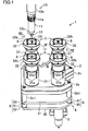
- FIG. 1 illustrates a rotary changer 1 for welding torches according to a first example which is not in the scope of the present invention.
- This rotary changer 1 is designed to automatically replace a metallic nozzle 11, which is an exemplary torch component of a welding torch 10 for use to weld a steel plate, for example, by arc welding.
- this welding torch 10 includes a circular columnar torch body 10a, and the nozzle 11 having a cylindrical shape is screwed on, and coupled to, a tip portion of the torch body 10a.
- the tip portion of the nozzle 11 has a tapered shape, of which the diameter gradually decreases toward an opening at the tip end. Meanwhile, a base-end outer peripheral surface of the nozzle 11 has a knurled engaging portion 11a extending in the circumferential direction.
- the engaging portion 11a has a large number of teeth and spaces which extend along the center axis of the nozzle 11 and which are arranged alternately around the center axis.
- a copper contact tip 12 (which is an exemplary torch component) in a fine bar shape is screwed on, and coupled to, the tip of the torch body 10a.
- the tip portion of the contact tip 12 sticks out of the opening at the tip end of the nozzle 11.
- a portion of the contact tip 12 covering a middle through the tip of its outer peripheral surface has a tapered shape, of which the diameter gradually decreases toward the tip of the contact tip 12.
- the outer peripheral surface of the contact tip 12 also has two flat portions 12b which are parallel to each other with the center axis interposed between them and which are located closer to the base end.
- this rotary changer 1 includes a gearbox 2 having an arrow shape in a plan view, three cylindrical rotators 3 provided on the upper surface of the gearbox 2, and a tilt unit 4 having a substantially triangular shape in a plan view.
- the gearbox 2 is comprised of a thick triangular plate portion 2a and a thick rectangular plate portion 2b continuous with the triangular plate portion 2a.
- the tilt unit 4 is arranged under the triangular plate portion 2a of the gearbox 2 in parallel with the gearbox 2.
- the three corners of the triangular plate portion 2a of the gearbox 2 and the three corners of the tilt unit 4 are respectively coupled together with vertically extending coupling shafts Sh1.
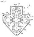
- a motor 5 to be activated when supplied with compressed air is mounted to the lower surface of the rectangular plate portion 2b of the gearbox 2.
- the output shaft 5a of the motor 5 extends vertically and faces the inside of the rectangular plate portion 2b of the gearbox 2 as shown in FIG. 5 .
- the motor 5 is supposed to operate under air control.
- a servo control motor may be used instead.
- a substantially disklike input gear 21 rotatable on a rotational axis C1 that extends vertically.
- the output shaft 5a is connected to the center of the input gear 21.
- An idler gear 22 meshing with the input gear 21 is provided to be rotatable on a rotational axis C2 extending vertically and is arranged inside the triangular plate portion 2a of the gearbox 2 and adjacent to the rectangular plate portion 2b.
- the upper surface of the triangular plate portion 2a has three upper through holes 2c with a circular cross section as shown in FIG. 4 .
- the lower surface of the triangular plate portion 2a has three lower through holes 2d, each squarely facing an associated one of the upper through holes 2c.
- a substantially disklike output gear 23 is arranged between each associated pair of the upper and lower through holes 2c and 2d.
- the output gear 23 has a horizontally broad and vertically projecting pivot 23a at its center.
- the pivot 23a has a gear recess 23b that forms an upward opening.
- a cylindrical guide member 24 is fitted into the gear recess 23b so as to protrude out of the opening of the gear recess 23b.
- An upper end portion of the pivot 23a is fitted into the upper through hole 2c, while a lower end portion of the pivot 23a is fitted into the lower through hole 2d.
- the output gear 23 meshes with the idler gear 22, and is rotatable on a vertically extending rotational axis C3 by having upper and lower end portions of the pivot 23a supported rotatably by the triangular plate portion 2a via bearings B1 and B2, respectively.
- the rotator 3 includes a first cylindrical member 31 secured to the output gear 23 such that its center axis extends vertically so as to be aligned with the rotational axis C3. As shown in FIGS. 1 and 2 , an upper half portion of the first cylindrical member 31 has four vertically elongated slits 31a which are arranged at regular intervals around the center axis of the cylinder.
- a second cylindrical member 32 with a vertically extending center axis is inserted from above into the first cylindrical member 31.
- the respective center axes of the first and second cylindrical members 31 and 32 agree with each other.
- a cap member 33 is fitted into the lower portion of the second cylindrical member 32 to close the bottom opening of the second cylindrical member 32.
- the cap member 33 and the second cylindrical member 32 together form a hollow 30 opening at the upper end (i.e., at one end of the rotator).
- the upper surface of the cap member 33 has a housing recess 33a at its center. Meanwhile, the lower surface of the cap member 33 has a protrusion 33b, corresponding to the housing recess 33a and protruding downward, at its center.
- An upper end portion of the second cylindrical member 32 has an annular projection 32b projecting outward and sideward and extending around the center axis. Inside the annular projection 32b, a recessed groove 32c has been formed to extend along the annular projection 32b.
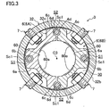
- an interlocking member 6 having a generally annular shape in a plan view as shown in FIG. 3 .
- the outer peripheral portion of the interlocking member 6 is freely fitted into the recessed groove 32c.
- This interlocking member 6 is divided, virtually along a horizontal centerline, into a generally C-shaped first member 6A located on one side of the line and a generally C-shaped second member 6B located on the other side of the line.
- the first member 6A has, at its middle portion facing away from the second member 6B, a first expanding portion 6a expanding outward and sideward and having a generally rectangular shape in a plan view.
- An insertion hole 6b runs vertically through a middle of the first expanding portion 6a.
- the first member 6A also has, at both ends thereof, a pair of second expanding portions 6c also expanding outward and sideward.
- a portion of each of these second expanding portions 6c facing the second member 6B has a guide groove 6d extending vertically and opening at the top and bottom.
- a portion of the first member 6A facing the second member 6B and located between the two guide grooves 6d is an interlocking groove 60 opening not only toward the second member 6B but also at top and bottom ends as well.
- the interlocking groove 60 has a recessed shape to mesh with a half of the outer peripheral surface of the nozzle 11.
- Portions of the inner peripheral surface of the interlocking groove 60 that are located between the first expanding portion 6a and the respective second expanding portions 6c function as engageable portions 60a engageable with the engaging portion 11a of the nozzle 11.
- the engageable portions 60a have respective teeth and spaces that are engageable with their corresponding spaces and teeth of the engaging portion 11a and arranged alternately along an arc inner peripheral surface of the interlocking groove 60.
- the second member 6B has the same structure as the first member 6A and is only arranged horizontally symmetrically to the first member 6A in a plan view.
- the respective portions of the second member 6B will be identified by the same reference numerals as those of their counterparts of the first member 6A and detailed description thereof will be omitted herein.
- This interlocking member 6 is mounted to the second cylindrical member 32 with screws Sc1 screwed into the respective insertion holes 6b and the mutually facing guide grooves 6d. Before being screwed up, the interlocking member 6 is arranged such that the respective interlocking grooves 60 of the first and second members 6A and 6B face each other and that one guide groove 6d of the first member 6A faces one guide groove 6d of the second member 6B and that the other guide groove 6d of the first member 6A faces the other guide groove 6d of the second member 6B.
- the interlocking member 6 is configured such that when the interlocking member 6 is mounted to the second cylindrical member 32, gaps S1 and S2 respectively are left between the inner peripheral surface of each insertion hole 6b and the outer peripheral surface of a screw Sc1 screwed therein and between the inner peripheral surface of each pair of guide grooves 6d and the outer peripheral surface of a screw Sc1 screwed therein. That is to say, the interlocking member 6 is allowed to turn on the rotational axis C3 or move horizontally with respect to the second cylindrical member 32 to the degrees allowed by those gaps S1 and S2.
- interlocking member 6 is designed to be rotatable about 0-5 degrees on the rotational axis C3.
- ball plungers 7 (first biasing means) are arranged at regular intervals between the interlocking member 6 and the recessed groove 32c and around the rotational axis C3. Each of these ball plungers 7 is configured such that its ball contacts with the surface of the interlocking member 6 between the first and second expanding portions 6a and 6b thereof to bias the interlocking member 6 toward the rotational axis C3.
- a coil spring 8 (second biasing means) is arranged inside the first cylindrical member 31. An upper portion of the coil spring 8 is externally engaged with the protrusion 33b of the cap member 33, while a lower portion of the coil spring 8 is housed inside the guide member 24 so as to bias the second cylindrical member 32 upward (i.e., toward one end of the rotator).
- the welding torch 10 is inserted into the hollow 30 of each rotator 3 from over the rotator 3 such that the center axis of the welding torch 10 is aligned with the rotational axis C3, and moved along the rotational axis C3.
- driving the output shaft 5a of the motor 5 in one direction allows each rotator 3 to rotate clockwise (i.e., in the direction X1) on the rotational axis C3 via the input gear 21, idler gear 22 and three output gears 23.
- the engaging portion 11a gets engaged with the engageable portion 60a, thereby getting the interlocking member 6 interlocked with the outer peripheral surface of the nozzle 11.
- rotating the rotator 3 clockwise while inserting the welding torch 10 into the hollow 30 allows the second cylindrical member 32 to slide toward the first cylindrical member 31 against the biasing force of the coil spring 8 since the engaging portion 11a has contacted with the engageable portion 60a and until the respective teeth and spaces of the engaging portion 11a face their counterparts of the engageable portion 60a. Thereafter, when the respective teeth and spaces of the engaging portion 11a face their counterparts of the engageable portion 60a, the nozzle 11 starts to move downward and the second cylindrical member 32 starts to slide upward under the biasing force of the coil spring 8, thus causing the engaging portion 11a to get engaged with the engageable portion 60a and also causing the interlocking member 6 to get interlocked with the outer peripheral surface of the nozzle 11.
- the tip of the contact tip 12 is housed in the housing recess 33a and the opening peripheral edge of the nozzle 11 contacts with that of the housing recess 33a.
- the rotator 3 is configured to remove the nozzle 11 from the tip portion of the torch body 10a by rotating clockwise with the interlocking member 6 interlocked with the nozzle 11.
- this rotary changer 1 is also configured to allow the nozzle 11 to be screwed on, and coupled to, the tip portion of the torch body 10a by setting the nozzle 11 in place into the hollow 30 such that the interlocking member 6 gets interlocked with the nozzle 11 and by rotating the rotator 3 counterclockwise (i.e., in the direction X2) while bringing the torch body 10a closer to the rotator 3 from over the rotator 3.
- this rotary changer 1 is designed to replace the nozzle 11 to be screwed on, and coupled to, the tip portion of the torch body 10a by rotating the rotator 3 either clockwise or counterclockwise.
- the tilt unit 4 includes a supporting plate 41 having a generally triangular shape in a plan view, and a base plate 42 provided on the other side of the supporting plate 41 opposite from the rotators 3 and in parallel with the supporting plate 41 and also having a generally triangular shape in a plan view.
- the supporting plate 41 supports the respective rotators 3 via the gearbox 2 and the respective coupling shafts Sh1.
- the base plate 42 has a first fitting hole 42a at a substantially center thereof, and also has first mounting holes 42b at three corners thereof.
- the supporting plate 41 has a second fitting hole 41a at a substantially center thereof, and also has second mounting holes 41b at respective positions corresponding to the first mounting holes 42b.
- a tilt maintaining mechanism 43 (tilt maintaining means) for keeping the supporting plate 41 tilted with respect to the base plate 42 is provided between the supporting plate 41 and base plate 42 and around the center of the supporting and base plates 41 and 42.
- the tilt maintaining mechanism 43 includes a generally disklike first supporting member 44, of which the lower portion functions as a first fitting portion 44a to be fitted into the first fitting hole 42a.
- the first supporting member 44 is secured to the base plate 42 by having the first fitting portion 44a fitted into the first fitting hole 42a.
- the upper surface of the first supporting member 44 has a curved recess 44b, of which the diameter gradually decreases toward the portion of the first supporting member 44 secured to the base plate 42.
- the tilt maintaining mechanism 43 also includes a generally disklike second supporting member 45, of which the upper portion functions as a second fitting portion 45a to be fitted into the second fitting hole 41a.
- the second supporting member 45 is secured to the supporting plate 41 by having the second fitting portion 45a fitted into the second fitting hole 41a.
- the lower surface of the second supporting member 45 has a curved projection 45b to be fitted slidably into the curved recess 44b.
- three stretchers 9 which stretch and shrink vertically (i.e., along the rotational axis) are provided between the three corners of the supporting plate 41 and the three corners of the base plate 42.
- Each of the stretchers 9 includes a rubber portion 91 of silicone rubber having, on a side view, a generally Japanese hand drum shape, of which the diameter gradually decreases from top and bottom toward the middle.
- Each stretcher 9 may have its bottom portion (i.e., the other end) fixed to the base plate 42 by having the first projection 92a thereof fitted into an associated one of the first mounting holes 42b of the base plate 42.
- each stretcher 9 may have its top portion (i.e., one end) fixed to the supporting plate 41 by having the second projection 93a thereof fitted into an associated one of the second mounting holes 41b of the supporting plate 41.
- a welding torch 10 is transported by an industrial robot (not shown) to a predetermined standby position over one of the four rotators as shown in FIG. 9 .
- the welding torch 10 is inserted from over the rotator 3 into the hollow 30 thereof such that its center axis is aligned with the rotational axis C3. Then, the engaging portion 11a comes into contact with the engageable portion 60a, thus allowing the second cylindrical member 32 to start to slide downward against the biasing force of the coil spring 8.
- the motor 5 is activated to turn its output shaft 5a in one direction and thereby trigger clockwise rotation (i.e., rotation in the direction X1) of each rotator 3 on the rotational axis C3 via the input gear 21, idler gear 22, and output gears 23.
- the respective teeth and spaces of the engaging portion 11a face their counterparts of the engageable portion 60a, thereby allowing the nozzle 11 to go downward and the second cylindrical member 32 to slide upward under the biasing force of the coil spring 8.
- the engaging portion 11a soon gets engaged with the engageable portion 60a to have the interlocking member 6 interlocked with the outer peripheral surface of the nozzle 11.
- the tip of the contact tip 12 gets housed in the housing recess 33a, and the opening peripheral edge at the tip of the nozzle 11 abuts with that of the housing recess 33a.
- the respective center axes of the tip portion of the torch body 10a and the nozzle 11 may be misaligned with the rotational axis C3 of the rotator 3.
- the misalignment causes the interlocking member 6 to shift in the direction of the misalignment and get interlocked with the outer peripheral surface of the nozzle 11 as each of the ball plungers 7 stretches and shrinks.
- the respective ball plungers 7 keep the interlocking member 6 misaligned such that the rotation of the rotator 3 causes the interlocking member 6 to rotate on the center axis of the nozzle 11.
- the nozzle 11 starts to rotate on the respective center axes of the tip portion of the torch body 10a and the nozzle 11 that are still misaligned with the rotational axis C3 of the rotator 3. This substantially eliminates the imposition of unnecessary load on the tip portion of the torch body 10a while the nozzle 11 is being removed, which thus significantly reduces failures of welding torches 10.
- the nozzle 11 is set in place in the hollow 30 of one of the four rotators 3 as shown in FIG. 11 . Specifically, while the nozzle 11 is inserted into the hollow 30 of the rotator 3, the engaging portion 11a of the nozzle 11 is brought into engagement with the engageable portion 60a of the interlocking member 6.
- the torch body 10a is transported by an industrial robot (not shown) to a predetermined standby position over the rotator 3 in which the nozzle 11 has been set.
- the torch body 10a is moved downward to bring its tip portion into contact with the opening peripheral edge at the base end of the nozzle 11. This causes the second cylindrical member 32 to start to slide downward against the biasing force of the coil spring 8.
- the nozzle 11 starts to get screwed on, and coupled to, the tip portion of the torch body 10a such that its center axis is shifted to get aligned with that of the tip portion of the torch body 10a as each of the ball plungers 7 stretches and shrinks.
- the nozzle 11 may be mounted onto the tip portion of the torch body 10a while rotating on the center axis of the tip portion of the torch body 10a with their respective center axes aligned with each other. This substantially eliminates the imposition of unnecessary load on the tip portion of the torch body 10a while the nozzle 11 is being mounted, which thus significantly reduces the failure of the welding torches 10.
- the rotary changer 1 allows the nozzle 11 and the interlocking member 6 to change their relative positions in a direction intersecting with the rotational axis C3.
- an outer peripheral portion of the nozzle 11 may contact with the engageable portion 60a of the interlocking member 6 in the meantime.
- bringing the outer peripheral portion of the nozzle 11 into sliding contact with the engageable portion 60a of the interlocking member 6 still allows the interlocking member 6 to move such that the position of the engageable portion 60a agrees with that of the outer peripheral surface of the nozzle 11. This results in avoidance of deformation or damage around the interlocking member 6.
- the engaging portion 11a is a knurled one.
- rotating the rotator 3 while inserting the welding torch 10 into the hollow 30 makes the engaging portion 11a of the nozzle 11 contact with the engageable portion 60a of the interlocking member 6 first and then allows the respective teeth and spaces of the engaging portion 11a to face, and mesh with, their counterparts of the engageable portion 60a at predetermined timings.
- This allows the engaging portion 11a to get engaged with the engageable portion 60a while letting the nozzle 11 move downward. Consequently, simply inserting the welding torch 10 into the hollow 30 allows the nozzle 11 and interlocking member 6 to get interlocked with each other.
- the respective ball portions of the ball plungers 7 reduce the frictional resistance between the ball plungers 7 and the interlocking member 6 moving through the hollow 30. This thus allows the interlocking member 6 to be smoothly moved to a position facing the nozzle 11.
- inserting the welding torch 10 in a tilted position into the hollow 30 of the rotator 3 causes the supporting plate 41 to get tilted with respect to the tilt maintaining mechanism 43 to the same degree as the welding torch 10 and also allows each stretcher 9 to stretch or shrink to a degree corresponding to the tilt of the supporting plate 41.
- the nozzle 11 may also be replaced with no load imposed on the torch body 10a.
- the sliding contact between the curved projection and curved recess 45b, 44b of the tilt maintaining mechanism 43 allows the supporting plate 41 to smoothly tilt toward any direction.
- the supporting plate 41 may be tilted flexibly to any desired degree corresponding to the specific degree of tilt each time.
- the stretcher 9 may be stretched with a simple structure, which lowers the manufacturing unit price of the stretcher 9, and ultimately, cuts down the overall cost of the rotary changer 1.
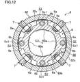
- FIG. 12 illustrates an internal structure of a rotator 3 in a rotary changer 1 according to a second example which is not in the scope of the present invention.
- This second example is the same as the first example except that an interlocking member 6 according to the second example has a different structure from the counterpart of the first example.
- the following description of the second example will be focused on only the difference from the first example.
- the interlocking member 6 of the second example has an annular shape, and has a through hole 60b (as an exemplary interlocking portion) running through the member 6 vertically (i.e., along the rotational axis C3) and allowing the nozzle 11 of the welding torch 10 to pass through itself.
- first expanding portions 6a are provided at respective positions on the outer peripheral edge of the interlocking member 6 that correspond to the respective engageable portions 60a. According to this second example, however, no second expanding portions 6c are provided unlike the first example. Additionally, between each pair of the first expanding portions 6a on the outer peripheral edge of the interlocking member 6, there is an inwardly dented step portion 6e having a generally rectangular shape in a plan view.
- the interlocking member 6 is configured such that when the interlocking member 6 is mounted to the second cylindrical member 32, a gap S1 is left between the inner peripheral surface of each insertion hole 6b and the outer peripheral surface of a screw Sc1 screwed therein. That is to say, the interlocking member 6 is allowed to turn on the center axis, or move horizontally, with respect to the second cylindrical member 32 to the degree allowed by the gap S1 left there.
- this interlocking member 6 is arranged in the hollow 30 such that the respective ball plungers 7 face the respective step portions 6e.
- Each of these ball plungers 7 is configured such that its ball contacts with the surface of an associated one of the step portions 6e to bias the interlocking member 6 toward the rotational axis C3.
- the second example has the same advantages as the first example described above.
- the annular interlocking member 6 of this example is rigid enough to prevent the rotary changer 1 from getting out of order easily even after having gone through repetitive replacements.
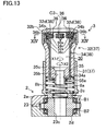
- FIGS. 13-17 depict a rotary changer 1 according to a first embodiment of the present disclosure.
- This first embodiment is the same as the first example except that a rotator 3, a welding torch 10, and output gears 23 of the first embodiment have different structures from the counterparts of the first example.
- the following description of the first embodiment will be focused on only the difference from the first example.
- Each output gear 23 according to this first embodiment has a communication hole 23c as a center hole vertically running through the gear 23 as shown in FIG. 13 .
- the nozzle 11 also has the engaging portion 11a halfway on its outer peripheral surface.
- the lower portion of the nozzle 11 closer to the tip than the engaging portion 11a is has a tapered outer peripheral surface with a diameter gradually decreasing toward the tip as shown in FIGS. 15-17 .
- the first cylindrical member 31 of the first embodiment has a bottom opening, which has a smaller diameter than its top opening and of which the peripheral edge is fitted into the upper through hole 2c of the gearbox 2.
- first cylindrical member 31 of the first embodiment has no slits 31a unlike the counterpart 31 of the first example.
- each of these recesses 32d gradually slopes toward the rotational axis C1 as the point of interest moves downward (i.e., toward the other end of the rotator along the rotational axis C1) as shown in FIG. 13 .
- a generally cylindrical sliding member 34 (sliding portion) having a center axis aligned with the rotational axis C1 is fitted and inserted so as to be slidable vertically.
- the sliding member 34 has the hollow 30 that forms an upward opening, and has a fitting hole 34a at the center of its bottom.
- first and second cylindrical members 31 and 32 according to the first embodiment together form a rotary case 37 according to the present disclosure, which houses the sliding member 34 in a slidable state.
- a pressable member 35 having a convex cross section is fitted inside the bottom of the sliding member 34.
- the pressable member 35 has a downwardly protruding fitting portion 35a at the center of its lower surface.
- the fitting portion 35a fits into the fitting hole 34a and projects out of the fitting hole 34a into the inner space of the first cylindrical member 31.
- the pressable member 35 has a tip avoiding hole 35b running vertically along the center axis of the member 35.
- the top opening of the tip avoiding hole 35b has a diameter-decreasing portion 35c, of which the diameter decreases downward so as to come gradually closer to the rotational axis C1 as the point of interest moves downward.
- protrusions 34b are provided at respective positions facing the recesses 32d so as to protrude outward and sideward. These protrusions 34b are provided to get hooked with the opening peripheral edge at the top of each recess 32d when the sliding member 34 slides upward to reach the protrusions 34b and to stop the sliding member 34 from sliding further upward.
- the sliding member 34 also has guide holes 34c, which have been cut through the peripheral wall of the sliding member 34 and which are located under the respective protrusions 34b.
- a moving block 36 (interlocking member) is fitted and inserted into each of the guide holes 34c such that each guide hole 34c guides the movement of its associated moving block 36 in a direction intersecting with the rotational axis C3.
- Each moving block 36 has the engageable portion 60a (interlocking portion) on one side thereof that faces the rotational axis C3.
- each moving block 36 On the other side of each moving block 36 opposite from the rotational axis C3, the moving block 36 has a broadened portion 36b having a vertically broader width than any other portion thereof.
- the broadened portion 36b has a slidable surface 36c (i.e., a first sloping surface) sloping toward the rotational axis C3 as the point of interest goes downward.
- the slidable surface 36c contacts slidably with the bottom 32e of its associated recess 32d.
- a smaller coil spring 8a and a larger coil spring 8b Inside the first cylindrical member 31, arranged are a smaller coil spring 8a and a larger coil spring 8b.
- the smaller coil spring 8a is located inside the larger coil spring 8b such that their centers of spring agree with each other.
- An upper portion of the smaller coil spring 8a is mounted on the outer surface of the fitting portion 35a.
- a lower portion of the smaller coil spring 8a is not only inserted into the bottom opening of the first cylindrical member 31 but also abuts with the opening peripheral edge at the top of the communication hole 23c of the output gear 23, thus biasing the sliding member 34 upward.
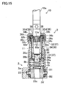
- the welding torch 10 is inserted from over the rotator 3 into the hollow 30 thereof such that its center axis is aligned with the rotational axis C3 and moved downward along the rotational axis C3, the tip of the contact tip 12 is inserted into the tip avoiding hole 35b of the pressable member 35 and a tip portion of the nozzle 11 comes into contact with the decreasing diameter portion 35c as shown in FIG. 16 . As a result, the pressable portion 35 is pressed downward by the welding torch 10.
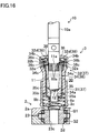
- each recess 32d of the second cylindrical member 32 makes sliding contact with the slidable surface 36c of an associated moving block 36 that moves downward along with the sliding member 34 sliding downward with respect to the second cylindrical member 32, thereby pressing the moving block 36 toward the rotational axis C3.
- the moving blocks 36 thus pressed are guided along the respective guide holes 34c to move toward the rotational axis C3.
- the respective recesses 32d are configured to allow their associated moving blocks 36 to move toward the rotational axis C3 synchronously with downward sliding of the sliding member 34.
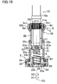
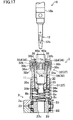
- the rotator 3 rotates clockwise (i.e., in the direction X1) as shown in FIG. 17 with the respective moving blocks 36 interlocked with the nozzle 11, thereby turning the nozzle 11 on its center axis and removing the nozzle 11 from the tip portion of the torch body 10a.
- the nozzle 11 may be turned on its center axis in the following manner. Specifically, the sliding member 34 may be allowed to slide downward with respect to the second cylindrical member 32 with pressure applied downward from the torch body 10a to the nozzle 11 already placed in position in the hollow 30. In the meantime, the rotator 3 may be allowed to rotate counterclockwise (i.e., in the direction X2) with the respective moving blocks 36 moved toward the rotational axis C3 to bring the engaging portion 11a of the nozzle 11 into engagement with the engageable portions 60a of the respective moving blocks 36.
- the sliding member 34 may be allowed to slide downward with respect to the second cylindrical member 32 with pressure applied downward from the torch body 10a to the nozzle 11 already placed in position in the hollow 30.
- the rotator 3 may be allowed to rotate counterclockwise (i.e., in the direction X2) with the respective moving blocks 36 moved toward the rotational axis C3 to bring the engaging portion 11a of the nozzle 11 into engagement with the engageable portions 60a of the respective moving blocks 36.
- a welding torch 10 is transported by an industrial robot (not shown) to a predetermined standby position over one of the three rotators 3 as shown in FIG. 13 .
- the welding torch 10 is inserted from over the rotator 3 into the hollow 30 thereof such that its center axis is aligned with the rotational axis C3. Then, the tip of the contact tip 12 is inserted into the tip avoiding hole 35b of the pressable member 35 and a tip portion of the nozzle 11 comes into contact with the decreasing diameter portion 35c. Thus, the welding torch 10 presses the pressable portion 35 downward.
- the pressable member 35 pressed downward by the welding torch 10 starts to slide, along with the sliding member 34, downward with respect to the second cylindrical member 32 against the biasing force of the smaller coil spring 8a.
- the respective moving blocks 36 also move downward along with the sliding member 34 to bring the slidable surface 36c of each of the moving blocks 36 into sliding contact with the bottom 32e of its associated recess 32d of the second cylindrical member 32.
- force is applied to press the respective moving blocks 36 toward the rotational axis C3 as shown in FIG. 16 .
- the respective moving blocks 36 move toward the rotational axis C3 to bring the engageable portions 60a into engagement with the engaging portion 11a of the nozzle 11.
- the nozzle 11 prevents the respective moving blocks 36 from moving toward the rotational axis C3 any farther, thus stopping the sliding contact between the respective bottoms 32e of the recesses 32d and the respective slidable surfaces 36c of the moving blocks 36.
- the motor 5 is activated to trigger clockwise rotation (i.e., rotation in the direction X1) of each rotator 3 on the rotational axis C3 via the input gear 21, idler gear 22, and output gears 23.
- clockwise rotation i.e., rotation in the direction X1
- the motor 5 is activated to trigger clockwise rotation (i.e., rotation in the direction X1) of each rotator 3 on the rotational axis C3 via the input gear 21, idler gear 22, and output gears 23.
- the nozzle 11 is set in place in the hollow 30 of one of the four rotators 3 as shown in FIG. 17 .
- the torch body 10a is transported by an industrial robot (not shown) to a predetermined standby position over the rotator 3 in which the nozzle 11 has been set.
- the torch body 10a is moved downward to bring its tip into contact with the opening peripheral edge at the base end of the nozzle 11. This allows the sliding member 34 to be pressed by the nozzle 11 in contact with the diameter-decreasing portion 35c of the pressable member 35 and start sliding downward with respect to the second cylindrical member 32 against the biasing force of the smaller coil spring 8a.
- the respective moving blocks 36 also move downward along with the sliding member 34 to bring the slidable surface 36c of each of the moving blocks 36 into sliding contact with the bottom 32e of its associated recess 32d of the second cylindrical member 32. Then, force is applied to press the respective moving blocks 36 toward the rotational axis C3 as shown in FIG. 16 . As a result, the respective moving blocks 36 move toward the rotational axis C3 to bring the respective engageable portions 60a of the moving blocks 36 into engagement with the engaging portion 11a of the nozzle 11.
- the nozzle 11 prevents the respective moving blocks 36 from moving toward the rotational axis C3 any farther, thus stopping the sliding contact between the respective bottoms 32e of the recesses 32d and the respective slidable surfaces 36c of the moving blocks 36.
- the motor 5 is activated to trigger counterclockwise rotation (i.e., rotation in the direction X2) of each rotator 3 on the rotational axis C3 via the input gear 21, idler gear 22, and output gears 23.
- counterclockwise rotation i.e., rotation in the direction X2
- the motor 5 is activated to trigger counterclockwise rotation (i.e., rotation in the direction X2) of each rotator 3 on the rotational axis C3 via the input gear 21, idler gear 22, and output gears 23.
- the moving blocks 36 are movable away from the rotational axis C3 of the rotator 3.
- the moving blocks 36 may be moved in advance away from the rotational axis C3 to avoid contact with the nozzle 11. This results in minimized deformation or damage caused around the moving block 36.
- inserting the nozzle 11 into the hollow 30 of the rotator 3 allows the moving blocks 36 to move toward the rotational axis C3 and get interlocked with the outer peripheral surface of the nozzle 11. This eliminates the need to provide any separate drive source to actuate the moving blocks 36 and eventually cuts down the cost of the rotary changer 1. Additionally, pressing the engageable portions 60 of the moving blocks 36 against the outer peripheral surface of the nozzle 11 increases not only the degree of close contact, but also the linkage, between the nozzle 11 and the moving blocks 36 as well.
- the moving block 36 moves downward integrally with the sliding member 34 while moving toward the rotational axis C3.
- the rotary changer 1 is designed to replace the nozzle 11 at a tip portion of the torch body 10a.
- this embodiment is just exemplary one, not limiting.
- the rotary changer 1 may also be designed such that the flat surfaces 12b of the contact tip 12 get interlocked with the engageable portions 60a of the interlocking member 6 (or the moving blocks 36) and that the contact tip 12 is replaced by being rotated on its center axis.
- the interlocking member 6 is biased toward the rotational axis C3 by means of the ball plungers 7.
- the interlocking member 6 may be biased toward the rotational axis C3 by any other type of biasing means as well.
- the engaging portion 11a is configured as a knurled member. Nevertheless, the engaging portion 11a may also be formed by any other type of machining as long as the nozzle 11 inserted into the hollow 30 of the rotator 3 can get interlocked with the interlocking member 6 (or the moving blocks 36).
- the rotary changer 1 according to the first embodiment of the present disclosure includes the tilt unit 4 but may also be implemented without any tilt units 4.
- the stretcher 9 is stretchable and shrinkable due to the resilience of the rubber portion 91 in the first embodiment of the present disclosure, but may also stretch and shrink using some spring, for example.
- the second cylindrical member 32 and sliding member 34 are supposed to be biased upward with the coil spring 8 or the smaller and larger coil springs 8a and 8b in the first embodiment of the present disclosure, but may also be biased by any other type of spring for the same purpose.
- the rubber portion 91 made of silicone rubber in the first embodiment of the present disclosure may be made of butadiene rubber, chloroprene rubber, or any other suitable type of rubber as well.
- first and second supporting members 44 and 45 are secured to the base plate 42 and supporting plate 41, respectively.
- second and first supporting members 45 and 44 may be secured to the base plate 42 and supporting plate 41, respectively.
- the diameter-decreasing portion 35c may also have a tapered shape corresponding to that of the outer peripheral surface of the nozzle 11.
- the outer peripheral surface of the nozzle 11 smoothly fits into the diameter-decreasing portion 35c, thus stabilizing the position of the nozzle 11 such that the cylinder center axis of the nozzle 11 is aligned with the rotational axis C3.
- the cylinder center axis of the nozzle 11 may be aligned more easily with that of the tip portion of the torch body 10a. This thus allows the nozzle 11 to be attached to the torch body 10a more reliably.
- the present disclosure is useful for a rotary changer for welding torches configured to automatically replace a torch component such as a cylindrical nozzle or a contact tip bar to be screwed on, and coupled to, a tip portion of the body of a welding torch for use in arc welding.
- a torch component such as a cylindrical nozzle or a contact tip bar
Description
- The present disclosure relates to a rotary changer for welding torches configured to automatically replace a torch component such as a cylindrical nozzle or a contact tip bar to be screwed on, and coupled to, a tip portion of the body of a welding torch for use in arc welding.
- Changer assemblies for replacing torch components automatically and efficiently have been known in the art. Examples of such torch components include cylindrical nozzles and contact tip bars to be screwed on, and coupled to, a tip portion of the body of a welding torch for use in arc welding. A changer assembly of this type is disclosed, for example, in
Patent Document 1 and presents the base for the preamble ofclaim 1. - The assembly includes a plurality of changers, each having a recess that opens at the top. Each of those changers is designed to rotate on a rotational axis to be displaced vertically by a drive motor and a gear meshing mechanism. To remove the torch component from the torch body, the welding torch is inserted into the recess with the changer kept rotating, thereby getting the recess interlocked with the torch component and rotating the torch component along with the changer to allow the torch component to get removed from the torch body. Meanwhile, to attach the torch component to the torch body, the torch component is placed in the changer such that its tip end faces downward and the torch body is gradually lowered with the changer kept rotating. In this manner, the torch component is attached onto the torch body so as to be screwed onto the tip portion of the torch body.
- PATENT DOCUMENT 1: Japanese Unexamined Patent Publication No.
2002-192345 - The changer assembly of Japanese Unexamined Patent Publication No.
2002-192345 - In view of the foregoing background, it is therefore an object of the present disclosure to provide a rotary changer for welding torches configured to prevent a portion of the changer interlockable with the torch component from being significantly deformed or damaged while the torch component is repeatedly attached to, or removed from, the torch body.
- To achieve this object, the changer according to the present disclosure may be configured such that while the torch component is being inserted into a rotator configured to attach or remove the torch component to/from the torch body by rotating, that portion of the rotator interlockable with the torch component is arranged to avoid contact with the torch component. Alternatively, the changer may also be configured such that on contacting with the torch component, the interlockable portion of the rotator immediately starts going away from the torch component.
- Specifically, the present disclosure is directed to a rotary changer for welding torches configured to replace a cylindrical or bar-shaped torch component screwed on, and coupled to, a tip portion of the body of a welding torch. This changer may be implemented in at least one of the following embodiments.
- Specifically, a first aspect of the present disclosure is a rotary changer comprising: a rotator arranged rotatably on a rotational axis and having an opening located at one end of the rotator, and a hollow into which the torch component is insertable through the opening such that a center axis of the torch component is aligned with the rotational axis of the rotator; and an interlocking member configured to rotate integrally with the rotator and to be movable in a direction intersecting with the rotational axis. The interlocking member includes an interlocking portion provided on one side of the interlocking member facing the rotational axis. The interlocking portion is interlockable with the torch component. The rotator rotates with the interlocking portion interlocked with the torch component, thereby turning the torch component on its center axis to either remove or attach the torch component from/onto the tip portion of the torch component's body.
- Furthermore, the rotator comprises a cam means including a sliding portion and a cam portion. The sliding portion is slidable along its rotational axis and configured to slide toward the other end of the rotator when pressed by the torch component being inserted into the hollow.
- The cam portion is configured to move the interlocking member toward the rotational axis while the sliding portion is sliding toward the other end of the rotator.
- A second aspect of the present disclosure is an embodiment of the first aspect. In the second aspect, the rotator includes a rotary case configured to house the sliding portion in a slidable state. The other side of the interlocking member facing away from the rotational axis has a first sloping surface sloping toward the rotational axis as a point of interest moves toward the other end of the rotator. The sliding portion defines a cylinder having the hollow inside, and has a peripheral wall with a guide hole that guides the interlocking member in a direction intersecting with the rotational axis. The cam portion is provided for the rotary case, and has a second sloping surface causing the interlocking member to move toward the rotational axis by allowing the first sloping surface to make sliding contact with the second sloping surface while the sliding portion is sliding toward the other end of the rotator.
- According to an example not covered by the claims, a first biasing means for biasing the interlocking member toward the rotational axis is provided between the interlocking member and the rotator. The first biasing means includes a plurality of biasing means arranged at regular intervals around the rotational axis.
- According to an example not covered by the claims, the torch component is a cylindrical nozzle having, on its outer peripheral surface, a knurled engaging portion extending in a circumferential direction. The interlocking portion has an engageable portion engageable with the engaging portion. As the welding torch is moved along the rotational axis such that the center axis of the welding torch is aligned with the rotational axis, the engaging portion gets engaged with the engageable portion, thus allowing the interlocking member to get interlocked with the outer peripheral surface of the nozzle.
- According to an example not covered by the claims, the rotator includes: a first cylindrical member, of which the center axis is aligned with the rotational axis; a second cylindrical member, of which the center axis is aligned with the rotational axis and which is provided inside the first cylindrical member so as to be slidable along the rotational axis; and a second biasing means configured to bias the second cylindrical member toward the one end of the rotator. The hollow is provided inside the second cylindrical member.
- According to an example not covered by the claims, the first biasing means comprises ball plungers.
- According to an example not covered by the claims, the rotary changer includes:
a supporting plate configured to support the rotator; a base plate arranged in parallel with the supporting plate so as to face one side of the supporting plate opposite from the rotator; a tilt maintaining means arranged between the supporting plate and the base plate to maintain the tilt of the supporting plate with respect to the base plate; and a plurality of stretchable means configured to be stretchable along the rotational axis and arranged between the supporting plate and the base plate and around the tilt maintaining means. Each of the stretchable means has one end thereof secured to the supporting plate and the other end thereof secured to the base plate. - According to an example not covered by the claims, the tilt maintaining means includes: a first supporting member secured to one of the supporting plate or the base plate and having a curved recessed portion with a recess having a diameter gradually decreasing toward the secured portion of the first supporting member; and a second supporting member secured to the other of the supporting plate or the base plate and having a curved raised portion to be slidably fitted into the curved recessed portion.
- According to an example not covered by the claims, the stretchable means is comprised of: a stretchable rubber portion; and mounting portions configured to mount the rubber portion to the supporting plate and the base plate.
- According to the first aspect, the torch component and the interlocking member may have their relative positions changed in a direction intersecting with the rotational axis. Thus, while the torch component is being inserted into the hollow of the rotator, the interlocking member may be moved in advance away from the rotational axis to avoid accidental contact with the torch component. An outer peripheral portion of the torch component possibly contacts with the interlocking portion of the interlocking member. Even so, bringing the outer peripheral portion of the torch component into sliding contact with the interlocking portion of the interlocking member still allows the interlocking member to move such that the position of the interlocking portion agrees with that of the outer peripheral surface of the torch component. This results in avoidance of deformation or damage around the interlocking member.
- According to the first aspect, inserting the torch component into the hollow of the rotator allows the interlocking member to move toward the rotational axis and get interlocked with the outer peripheral surface of the torch component. This eliminates the need to provide any separate drive source to actuate the interlocking member and eventually cuts down the cost of the machine. In addition, pressing the interlocking portion of the interlocking member against the outer peripheral surface of the torch component increases not only the degree of close contact, but also the linkage, between the torch component and the interlocking member as well.
- According to the second aspect, the interlocking member moves integrally with the sliding portion and the torch component toward the other end of the rotator while moving toward the rotational axis. Thus, when the interlocking portion contacts with the outer peripheral surface of the torch component, no frictional resistance is produced between them, which significantly reduces the wear of the interlocking portion and the torch component.
- While the torch component and the interlocking member are getting interlocked with each other via the interlocking portion, the respective center axes of the tip portion of the torch body and the torch component may be misaligned with the rotational axis of the rotator. In that case, according to an example not covered by the claims, the misalignment causes the interlocking member to move in the direction of the misalignment and get interlocked with the torch component as each of the first biasing means stretches and shrinks. Then, the respective first biasing means keep the interlocking member misaligned such that the rotation of the rotator causes the interlocking member to turn on the center axis of the torch component. Thus, the torch component turns on the respective center axes of the tip portion of the torch body and the torch component that are still misaligned with respect to the rotational axis of the rotator. This substantially eliminates the imposition of unnecessary load on the tip portion of the torch body while the torch component is being removed, which thus significantly reduces failures of welding torches.
- Also, assume that the tip portion of the torch body is brought closer to, and eventually mounted onto, the torch component with the rotator allowed to rotate while the torch component is interlocked with the interlocking member and while the center axis of the tip portion of the torch body is misaligned with the rotational axis of the rotator. In that case, the torch component starts to get screwed on, and coupled to, the tip portion of the torch body such that its center axis is shifted to agree with that of the tip portion of the torch body as each of the first biasing means stretches and shrinks. Thus, the torch component may be mounted onto the tip portion of the torch body while rotating on the center axis of the tip portion of the torch body with their respective center axes aligned with each other. This substantially eliminates the imposition of unnecessary load on the tip portion of the torch body while the torch component is being mounted, which thus significantly reduces failures of welding torches.
- According to an example not covered by the claims, the engaging portion is a knurled one. Thus, rotating the rotator while inserting the welding torch into the hollow makes the engaging portion of the nozzle contact with the engageable portion of the interlocking member first and then allows the respective teeth and spaces of the engaging portion to face, and mesh with, their counterparts of the engageable portion at predetermined timings. This allows the engaging portion to get engaged with the engageable portion while letting the nozzle move toward the other end of the rotator. Consequently, simply inserting the welding torch into the hollow allows the nozzle and interlocking member to get interlocked with each other.
- According to an example not covered by the claims, rotating the rotator while inserting the welding torch into the hollow allows the second cylindrical member to slide toward the other end of the rotator against the biasing force of the second biasing means since the engaging portion has contacted with the engageable portion and until the respective teeth and spaces of the engaging portion face their counterparts of the engageable portion. As a result, the second biasing means absorbs the force applied to the second cylindrical member. Also, when the respective teeth and spaces of the engaging portion face their counterparts of the engageable portion, the nozzle moves toward the other end of the rotator and the second cylindrical member slides toward the one end of the rotator under the biasing force of the second biasing means, thus causing the engaging portion to get engaged with the engageable portion. This sufficiently reduces the load to be imposed on the rotator while the engaging portion is getting engaged with the engageable portion, thus making the machine less fragile and getting the engaging portion engaged more easily with the engageable portion.
- According to an example not covered by the claims, the respective ball portions of the ball plungers reduce the frictional resistance between the ball plungers and the interlocking member moving through the hollow. This thus allows the interlocking member to smoothly move to a position facing the torch component.
- According to an example not covered by the claims, inserting the welding torch in a tilted position into the hollow of the rotator causes the supporting plate to get tilted around the tilt maintaining means to the same degree as the welding torch and also allows each stretchable means to stretch or shrink to a degree corresponding to the tilt of the supporting plate. Thus, even if the welding torch in such a tilted position is inserted into the hollow of the rotator, the torch component may also be replaced with no load imposed on the torch body.
- According to an example not covered by the claims, the sliding contact between the curved raised and recessed portions of the tilt maintaining means allows the supporting plate to smoothly tilt toward any direction. Thus, even if the welding torch tilts to varying degrees every time the torch component is replaced at the tip portion of the torch body, the supporting plate may be tilted flexibly to any desired degree corresponding to the specific degree of tilt each time.
- According to an example not covered by the claims, the stretchable means is allowed to stretch and shrink with a simple structure, which lowers the manufacturing unit price of the stretchable means, and ultimately, cuts down the overall cost of the machine.
-
-
FIG. 1 is a perspective view illustrating a rotary changer for welding torches according to a first example not covered by the claims. -
FIG. 2 is an exploded perspective view illustrating a rotator and its associated parts of the rotary changer. -
FIG. 3 is a cross-sectional view taken along the plane III-III shown inFIG. 1 . -
FIG. 4 is a cross-sectional view taken along the plane IV-IV shown inFIG. 1 . -
FIG. 5 is a plan view illustrating how respective gears mesh with each other inside a gearbox. -
FIG. 6 is a perspective view illustrating a tilt unit. -
FIG. 7 is an exploded perspective view of the tilt unit shown inFIG. 6 . -
FIG. 8 is a cross-sectional view taken along the plane VIII-VIII shown inFIG. 6 . -
FIG. 9 is a view corresponding to the cross-sectional view shown inFIG. 4 and illustrating either a state where a nozzle is on the verge of being removed from the tip portion of a torch body or a state where the nozzle has just been attached to the tip portion of the torch body. -
FIG. 10 is a view corresponding to the cross-sectional view shown inFIG. 4 and illustrating either a state where a nozzle is being removed from the tip portion of a torch body or a state where the nozzle is being attached to the tip portion of the torch body. -
FIG. 11 is a view corresponding to the cross-sectional view shown inFIG. 4 and illustrating either a state where a nozzle has just been removed from the tip portion of a torch body or a state where the nozzle is on the verge of being attached to the tip portion of the torch body. -
FIG. 12 is a view corresponding toFIG. 3 according to a second example not covered by the claims. -
FIG. 13 is a view corresponding toFIG. 4 according to a third exemplary embodiment of the present disclosure. -
FIG. 14 is a cross-sectional view taken along the plane XIV-XIV shown inFIG. 13 . -
FIG. 15 is a view corresponding toFIG. 9 according to a first embodiment. -
FIG. 16 is a view corresponding toFIG. 10 according to the first embodiment. -
FIG. 17 is a view corresponding toFIG. 11 according to the first embodiment. -
FIG. 1 illustrates arotary changer 1 for welding torches according to a first example which is not in the scope of the present invention. Thisrotary changer 1 is designed to automatically replace ametallic nozzle 11, which is an exemplary torch component of awelding torch 10 for use to weld a steel plate, for example, by arc welding. - As shown in
FIGS. 9-11 , thiswelding torch 10 includes a circularcolumnar torch body 10a, and thenozzle 11 having a cylindrical shape is screwed on, and coupled to, a tip portion of thetorch body 10a. - The tip portion of the
nozzle 11 has a tapered shape, of which the diameter gradually decreases toward an opening at the tip end. Meanwhile, a base-end outer peripheral surface of thenozzle 11 has aknurled engaging portion 11a extending in the circumferential direction. - That is to say, the engaging
portion 11a has a large number of teeth and spaces which extend along the center axis of thenozzle 11 and which are arranged alternately around the center axis. - A copper contact tip 12 (which is an exemplary torch component) in a fine bar shape is screwed on, and coupled to, the tip of the
torch body 10a. The tip portion of thecontact tip 12 sticks out of the opening at the tip end of thenozzle 11. - As shown in
FIG. 11 , a portion of thecontact tip 12 covering a middle through the tip of its outer peripheral surface has a tapered shape, of which the diameter gradually decreases toward the tip of thecontact tip 12. The outer peripheral surface of thecontact tip 12 also has twoflat portions 12b which are parallel to each other with the center axis interposed between them and which are located closer to the base end. - As shown in
FIG. 1 , thisrotary changer 1 includes agearbox 2 having an arrow shape in a plan view, threecylindrical rotators 3 provided on the upper surface of thegearbox 2, and atilt unit 4 having a substantially triangular shape in a plan view. Thegearbox 2 is comprised of a thicktriangular plate portion 2a and a thickrectangular plate portion 2b continuous with thetriangular plate portion 2a. Thetilt unit 4 is arranged under thetriangular plate portion 2a of thegearbox 2 in parallel with thegearbox 2. The three corners of thetriangular plate portion 2a of thegearbox 2 and the three corners of thetilt unit 4 are respectively coupled together with vertically extending coupling shafts Sh1. - A
motor 5 to be activated when supplied with compressed air is mounted to the lower surface of therectangular plate portion 2b of thegearbox 2. Theoutput shaft 5a of themotor 5 extends vertically and faces the inside of therectangular plate portion 2b of thegearbox 2 as shown inFIG. 5 . In the first example, themotor 5 is supposed to operate under air control. However, a servo control motor may be used instead. - Inside the
rectangular plate portion 2b of thegearbox 2, provided is a substantiallydisklike input gear 21 rotatable on a rotational axis C1 that extends vertically. Theoutput shaft 5a is connected to the center of theinput gear 21. - An
idler gear 22 meshing with theinput gear 21 is provided to be rotatable on a rotational axis C2 extending vertically and is arranged inside thetriangular plate portion 2a of thegearbox 2 and adjacent to therectangular plate portion 2b. - Around the three corners of the
triangular plate portion 2a of thegearbox 2, the upper surface of thetriangular plate portion 2a has three upper throughholes 2c with a circular cross section as shown inFIG. 4 . Meanwhile, the lower surface of thetriangular plate portion 2a has three lower throughholes 2d, each squarely facing an associated one of the upper throughholes 2c. - A substantially
disklike output gear 23 is arranged between each associated pair of the upper and lower throughholes - The
output gear 23 has a horizontally broad and vertically projectingpivot 23a at its center. Thepivot 23a has agear recess 23b that forms an upward opening. - A
cylindrical guide member 24 is fitted into thegear recess 23b so as to protrude out of the opening of thegear recess 23b. - An upper end portion of the
pivot 23a is fitted into the upper throughhole 2c, while a lower end portion of thepivot 23a is fitted into the lower throughhole 2d. - The
output gear 23 meshes with theidler gear 22, and is rotatable on a vertically extending rotational axis C3 by having upper and lower end portions of thepivot 23a supported rotatably by thetriangular plate portion 2a via bearings B1 and B2, respectively. - The
rotator 3 includes a firstcylindrical member 31 secured to theoutput gear 23 such that its center axis extends vertically so as to be aligned with the rotational axis C3. As shown inFIGS. 1 and2 , an upper half portion of the firstcylindrical member 31 has four verticallyelongated slits 31a which are arranged at regular intervals around the center axis of the cylinder. - A second
cylindrical member 32 with a vertically extending center axis is inserted from above into the firstcylindrical member 31. The respective center axes of the first and secondcylindrical members - To a vertically lower portion of the outer peripheral surface of the second
cylindrical member 32, fourpins 32a fitted into therespective slits 31a are attached as shown inFIG. 4 . Guiding these fourpins 32a inside therespective slits 31a allows the secondcylindrical member 32 to slide vertically (i.e., along the rotational axis) inside the firstcylindrical member 31. - A
cap member 33 is fitted into the lower portion of the secondcylindrical member 32 to close the bottom opening of the secondcylindrical member 32. Thecap member 33 and the secondcylindrical member 32 together form a hollow 30 opening at the upper end (i.e., at one end of the rotator). - The upper surface of the
cap member 33 has ahousing recess 33a at its center. Meanwhile, the lower surface of thecap member 33 has aprotrusion 33b, corresponding to thehousing recess 33a and protruding downward, at its center. - An upper end portion of the second
cylindrical member 32 has anannular projection 32b projecting outward and sideward and extending around the center axis. Inside theannular projection 32b, a recessedgroove 32c has been formed to extend along theannular projection 32b. - Inside an upper end portion of the second
cylindrical member 32, provided is an interlockingmember 6 having a generally annular shape in a plan view as shown inFIG. 3 . - The outer peripheral portion of the interlocking
member 6 is freely fitted into the recessedgroove 32c. - This interlocking
member 6 is divided, virtually along a horizontal centerline, into a generally C-shapedfirst member 6A located on one side of the line and a generally C-shapedsecond member 6B located on the other side of the line. - The
first member 6A has, at its middle portion facing away from thesecond member 6B, a first expandingportion 6a expanding outward and sideward and having a generally rectangular shape in a plan view. Aninsertion hole 6b runs vertically through a middle of the first expandingportion 6a. - The
first member 6A also has, at both ends thereof, a pair of second expandingportions 6c also expanding outward and sideward. A portion of each of these second expandingportions 6c facing thesecond member 6B has aguide groove 6d extending vertically and opening at the top and bottom. - A portion of the
first member 6A facing thesecond member 6B and located between the twoguide grooves 6d is an interlockinggroove 60 opening not only toward thesecond member 6B but also at top and bottom ends as well. The interlockinggroove 60 has a recessed shape to mesh with a half of the outer peripheral surface of thenozzle 11. - Portions of the inner peripheral surface of the interlocking
groove 60 that are located between the first expandingportion 6a and the respective second expandingportions 6c function asengageable portions 60a engageable with the engagingportion 11a of thenozzle 11. - That is to say, the
engageable portions 60a have respective teeth and spaces that are engageable with their corresponding spaces and teeth of the engagingportion 11a and arranged alternately along an arc inner peripheral surface of the interlockinggroove 60. - Note that the
second member 6B has the same structure as thefirst member 6A and is only arranged horizontally symmetrically to thefirst member 6A in a plan view. Thus, the respective portions of thesecond member 6B will be identified by the same reference numerals as those of their counterparts of thefirst member 6A and detailed description thereof will be omitted herein. - This interlocking
member 6 is mounted to the secondcylindrical member 32 with screws Sc1 screwed into therespective insertion holes 6b and the mutually facingguide grooves 6d. Before being screwed up, the interlockingmember 6 is arranged such that therespective interlocking grooves 60 of the first andsecond members guide groove 6d of thefirst member 6A faces oneguide groove 6d of thesecond member 6B and that theother guide groove 6d of thefirst member 6A faces theother guide groove 6d of thesecond member 6B. - The interlocking
member 6 is configured such that when the interlockingmember 6 is mounted to the secondcylindrical member 32, gaps S1 and S2 respectively are left between the inner peripheral surface of eachinsertion hole 6b and the outer peripheral surface of a screw Sc1 screwed therein and between the inner peripheral surface of each pair ofguide grooves 6d and the outer peripheral surface of a screw Sc1 screwed therein. That is to say, the interlockingmember 6 is allowed to turn on the rotational axis C3 or move horizontally with respect to the secondcylindrical member 32 to the degrees allowed by those gaps S1 and S2. - Note that the interlocking
member 6 is designed to be rotatable about 0-5 degrees on the rotational axis C3. - Four ball plungers 7 (first biasing means) are arranged at regular intervals between the interlocking
member 6 and the recessedgroove 32c and around the rotational axis C3. Each of theseball plungers 7 is configured such that its ball contacts with the surface of the interlockingmember 6 between the first and second expandingportions member 6 toward the rotational axis C3. - A coil spring 8 (second biasing means) is arranged inside the first
cylindrical member 31. An upper portion of thecoil spring 8 is externally engaged with theprotrusion 33b of thecap member 33, while a lower portion of thecoil spring 8 is housed inside theguide member 24 so as to bias the secondcylindrical member 32 upward (i.e., toward one end of the rotator). - Then, as shown in
FIG. 10 , thewelding torch 10 is inserted into the hollow 30 of eachrotator 3 from over therotator 3 such that the center axis of thewelding torch 10 is aligned with the rotational axis C3, and moved along the rotational axis C3. In the meantime, driving theoutput shaft 5a of themotor 5 in one direction allows eachrotator 3 to rotate clockwise (i.e., in the direction X1) on the rotational axis C3 via theinput gear 21,idler gear 22 and three output gears 23. As a result, the engagingportion 11a gets engaged with theengageable portion 60a, thereby getting the interlockingmember 6 interlocked with the outer peripheral surface of thenozzle 11. - Specifically, rotating the
rotator 3 clockwise while inserting thewelding torch 10 into the hollow 30 allows the secondcylindrical member 32 to slide toward the firstcylindrical member 31 against the biasing force of thecoil spring 8 since the engagingportion 11a has contacted with theengageable portion 60a and until the respective teeth and spaces of the engagingportion 11a face their counterparts of theengageable portion 60a. Thereafter, when the respective teeth and spaces of the engagingportion 11a face their counterparts of theengageable portion 60a, thenozzle 11 starts to move downward and the secondcylindrical member 32 starts to slide upward under the biasing force of thecoil spring 8, thus causing the engagingportion 11a to get engaged with theengageable portion 60a and also causing the interlockingmember 6 to get interlocked with the outer peripheral surface of thenozzle 11. In addition, the tip of thecontact tip 12 is housed in thehousing recess 33a and the opening peripheral edge of thenozzle 11 contacts with that of thehousing recess 33a. - Furthermore, as shown in
FIG. 11 , therotator 3 is configured to remove thenozzle 11 from the tip portion of thetorch body 10a by rotating clockwise with the interlockingmember 6 interlocked with thenozzle 11. - On the other hand, this
rotary changer 1 is also configured to allow thenozzle 11 to be screwed on, and coupled to, the tip portion of thetorch body 10a by setting thenozzle 11 in place into the hollow 30 such that the interlockingmember 6 gets interlocked with thenozzle 11 and by rotating therotator 3 counterclockwise (i.e., in the direction X2) while bringing thetorch body 10a closer to therotator 3 from over therotator 3. - As can be seen, this
rotary changer 1 is designed to replace thenozzle 11 to be screwed on, and coupled to, the tip portion of thetorch body 10a by rotating therotator 3 either clockwise or counterclockwise. - Referring to
FIGS. 6-8 , thetilt unit 4 includes a supportingplate 41 having a generally triangular shape in a plan view, and abase plate 42 provided on the other side of the supportingplate 41 opposite from therotators 3 and in parallel with the supportingplate 41 and also having a generally triangular shape in a plan view. The supportingplate 41 supports therespective rotators 3 via thegearbox 2 and the respective coupling shafts Sh1. - The
base plate 42 has a firstfitting hole 42a at a substantially center thereof, and also has first mountingholes 42b at three corners thereof. - On the other hand, the supporting
plate 41 has a secondfitting hole 41a at a substantially center thereof, and also has second mountingholes 41b at respective positions corresponding to the first mountingholes 42b. - A tilt maintaining mechanism 43 (tilt maintaining means) for keeping the supporting
plate 41 tilted with respect to thebase plate 42 is provided between the supportingplate 41 andbase plate 42 and around the center of the supporting andbase plates - The
tilt maintaining mechanism 43 includes a generally disklike first supportingmember 44, of which the lower portion functions as a firstfitting portion 44a to be fitted into the firstfitting hole 42a. The first supportingmember 44 is secured to thebase plate 42 by having the firstfitting portion 44a fitted into the firstfitting hole 42a. - The upper surface of the first supporting
member 44 has acurved recess 44b, of which the diameter gradually decreases toward the portion of the first supportingmember 44 secured to thebase plate 42. - The
tilt maintaining mechanism 43 also includes a generally disklike second supportingmember 45, of which the upper portion functions as a secondfitting portion 45a to be fitted into the secondfitting hole 41a. The second supportingmember 45 is secured to the supportingplate 41 by having the secondfitting portion 45a fitted into the secondfitting hole 41a. - The lower surface of the second supporting
member 45 has acurved projection 45b to be fitted slidably into thecurved recess 44b. - Furthermore, three stretchers 9 (stretchable means) which stretch and shrink vertically (i.e., along the rotational axis) are provided between the three corners of the supporting
plate 41 and the three corners of thebase plate 42. - Each of the
stretchers 9 includes arubber portion 91 of silicone rubber having, on a side view, a generally Japanese hand drum shape, of which the diameter gradually decreases from top and bottom toward the middle. - At the bottom of the
rubber portion 91, provided is a generally disklike first mountingportion 92 having afirst projection 92a at the center of the lower surface thereof. Eachstretcher 9 may have its bottom portion (i.e., the other end) fixed to thebase plate 42 by having thefirst projection 92a thereof fitted into an associated one of the first mountingholes 42b of thebase plate 42. - On the other hand, at the top of the
rubber portion 91, provided is a generally disklike second mountingportion 93 having asecond projection 93a at the center of the upper surface thereof. Eachstretcher 9 may have its top portion (i.e., one end) fixed to the supportingplate 41 by having thesecond projection 93a thereof fitted into an associated one of the second mountingholes 41b of the supportingplate 41. - Next, a specific procedure of removing the
nozzle 11 will be described as exemplary replacement work to be done by thisrotary changer 1. - First of all, after having done arc welding to a steel plate, for example, a
welding torch 10 is transported by an industrial robot (not shown) to a predetermined standby position over one of the four rotators as shown inFIG. 9 . - Next, as shown in
FIG. 10 , thewelding torch 10 is inserted from over therotator 3 into the hollow 30 thereof such that its center axis is aligned with the rotational axis C3. Then, the engagingportion 11a comes into contact with theengageable portion 60a, thus allowing the secondcylindrical member 32 to start to slide downward against the biasing force of thecoil spring 8. - Next, the
motor 5 is activated to turn itsoutput shaft 5a in one direction and thereby trigger clockwise rotation (i.e., rotation in the direction X1) of eachrotator 3 on the rotational axis C3 via theinput gear 21,idler gear 22, and output gears 23. - Then, the respective teeth and spaces of the engaging
portion 11a face their counterparts of theengageable portion 60a, thereby allowing thenozzle 11 to go downward and the secondcylindrical member 32 to slide upward under the biasing force of thecoil spring 8. As a result, the engagingportion 11a soon gets engaged with theengageable portion 60a to have the interlockingmember 6 interlocked with the outer peripheral surface of thenozzle 11. In addition, the tip of thecontact tip 12 gets housed in thehousing recess 33a, and the opening peripheral edge at the tip of thenozzle 11 abuts with that of thehousing recess 33a. - Thereafter, as shown in
FIG. 11 , further clockwise rotation of therotator 3 with the interlockingmember 6 interlocked with thenozzle 11 removes thenozzle 11 from the tip portion of thetorch body 10a. - At this time, the respective center axes of the tip portion of the
torch body 10a and thenozzle 11 may be misaligned with the rotational axis C3 of therotator 3. In that case, the misalignment causes the interlockingmember 6 to shift in the direction of the misalignment and get interlocked with the outer peripheral surface of thenozzle 11 as each of theball plungers 7 stretches and shrinks. Then, therespective ball plungers 7 keep the interlockingmember 6 misaligned such that the rotation of therotator 3 causes the interlockingmember 6 to rotate on the center axis of thenozzle 11. Thus, thenozzle 11 starts to rotate on the respective center axes of the tip portion of thetorch body 10a and thenozzle 11 that are still misaligned with the rotational axis C3 of therotator 3. This substantially eliminates the imposition of unnecessary load on the tip portion of thetorch body 10a while thenozzle 11 is being removed, which thus significantly reduces failures of welding torches 10. - Next, a specific procedure of attaching the
nozzle 11 will be described as exemplary replacement work to be done by thisrotary changer 1. - First of all, the
nozzle 11 is set in place in the hollow 30 of one of the fourrotators 3 as shown inFIG. 11 . Specifically, while thenozzle 11 is inserted into the hollow 30 of therotator 3, the engagingportion 11a of thenozzle 11 is brought into engagement with theengageable portion 60a of the interlockingmember 6. - Next, the
torch body 10a is transported by an industrial robot (not shown) to a predetermined standby position over therotator 3 in which thenozzle 11 has been set. - Subsequently, as shown in
FIG. 10 , thetorch body 10a is moved downward to bring its tip portion into contact with the opening peripheral edge at the base end of thenozzle 11. This causes the secondcylindrical member 32 to start to slide downward against the biasing force of thecoil spring 8. - After that, rotating the
rotator 3 counterclockwise (i.e., in the direction X2) with the secondcylindrical member 32 slid downward allows thenozzle 11 to start getting screwed onto the tip portion of thetorch body 10a. In this case, assume the tip portion of thetorch body 10a is brought closer to, and eventually mounted onto, thenozzle 11 with therotator 3 allowed to rotate while the center axis of the tip portion of thetorch body 10a is misaligned with the rotational axis C3 of therotator 3. In that case, thenozzle 11 starts to get screwed on, and coupled to, the tip portion of thetorch body 10a such that its center axis is shifted to get aligned with that of the tip portion of thetorch body 10a as each of theball plungers 7 stretches and shrinks. Thus, thenozzle 11 may be mounted onto the tip portion of thetorch body 10a while rotating on the center axis of the tip portion of thetorch body 10a with their respective center axes aligned with each other. This substantially eliminates the imposition of unnecessary load on the tip portion of thetorch body 10a while thenozzle 11 is being mounted, which thus significantly reduces the failure of the welding torches 10. - As can be seen from the foregoing description, the
rotary changer 1 according to the first embodiment of the present disclosure allows thenozzle 11 and the interlockingmember 6 to change their relative positions in a direction intersecting with the rotational axis C3. Thus, while thenozzle 11 is being inserted into the hollow 30 of therotator 3, an outer peripheral portion of thenozzle 11 may contact with theengageable portion 60a of the interlockingmember 6 in the meantime. Even so, bringing the outer peripheral portion of thenozzle 11 into sliding contact with theengageable portion 60a of the interlockingmember 6 still allows the interlockingmember 6 to move such that the position of theengageable portion 60a agrees with that of the outer peripheral surface of thenozzle 11. This results in avoidance of deformation or damage around the interlockingmember 6. - In addition, the engaging
portion 11a is a knurled one. Thus, rotating therotator 3 while inserting thewelding torch 10 into the hollow 30 makes theengaging portion 11a of thenozzle 11 contact with theengageable portion 60a of the interlockingmember 6 first and then allows the respective teeth and spaces of the engagingportion 11a to face, and mesh with, their counterparts of theengageable portion 60a at predetermined timings. This allows the engagingportion 11a to get engaged with theengageable portion 60a while letting thenozzle 11 move downward. Consequently, simply inserting thewelding torch 10 into the hollow 30 allows thenozzle 11 and interlockingmember 6 to get interlocked with each other. - Furthermore, rotating the
rotator 3 while inserting thewelding torch 10 into the hollow 30 allows the secondcylindrical member 32 to slide downward against the biasing force of thecoil spring 8 since the engagingportion 11a has contacted with theengageable portion 60a and until the respective teeth and spaces of the engagingportion 11a face their counterparts of theengageable portion 60a. As a result, thecoil spring 8 absorbs the force applied to the secondcylindrical member 32. Also, when the respective teeth and spaces of the engagingportion 11a face their counterparts of theengageable portion 60a, thenozzle 11 moves downward and the secondcylindrical member 32 slides upward under the biasing force of thecoil spring 8, thus causing the engagingportion 11a to get engaged with theengageable portion 60a. This sufficiently reduces the load to be imposed on therotator 3 while the engagingportion 11a is getting engaged with theengageable portion 60a, thus making therotary changer 1 less fragile and getting theengaging portion 11a engaged more easily with theengageable portion 60a. - Moreover, the respective ball portions of the
ball plungers 7 reduce the frictional resistance between theball plungers 7 and the interlockingmember 6 moving through the hollow 30. This thus allows the interlockingmember 6 to be smoothly moved to a position facing thenozzle 11. - In addition, inserting the
welding torch 10 in a tilted position into the hollow 30 of therotator 3 causes the supportingplate 41 to get tilted with respect to thetilt maintaining mechanism 43 to the same degree as thewelding torch 10 and also allows eachstretcher 9 to stretch or shrink to a degree corresponding to the tilt of the supportingplate 41. Thus, even if thewelding torch 10 in such a tilted position is inserted into the hollow 30 of therotator 3, thenozzle 11 may also be replaced with no load imposed on thetorch body 10a. - Besides, the sliding contact between the curved projection and
curved recess tilt maintaining mechanism 43 allows the supportingplate 41 to smoothly tilt toward any direction. Thus, even if thewelding torch 10 tilts to varying degrees every time thenozzle 11 is replaced with respect to the tip portion of thetorch body 10a, the supportingplate 41 may be tilted flexibly to any desired degree corresponding to the specific degree of tilt each time. - Moreover, the
stretcher 9 may be stretched with a simple structure, which lowers the manufacturing unit price of thestretcher 9, and ultimately, cuts down the overall cost of therotary changer 1. -
FIG. 12 illustrates an internal structure of arotator 3 in arotary changer 1 according to a second example which is not in the scope of the present invention. This second example is the same as the first example except that an interlockingmember 6 according to the second example has a different structure from the counterpart of the first example. Thus, the following description of the second example will be focused on only the difference from the first example. - The interlocking
member 6 of the second example has an annular shape, and has a throughhole 60b (as an exemplary interlocking portion) running through themember 6 vertically (i.e., along the rotational axis C3) and allowing thenozzle 11 of thewelding torch 10 to pass through itself. - In the second example, four
engageable portions 60a are arranged at regular intervals in the circumferential direction along the inner peripheral surface of the throughhole 60b. - Also, in this second example, four first expanding
portions 6a are provided at respective positions on the outer peripheral edge of the interlockingmember 6 that correspond to the respectiveengageable portions 60a. According to this second example, however, no second expandingportions 6c are provided unlike the first example. Additionally, between each pair of the first expandingportions 6a on the outer peripheral edge of the interlockingmember 6, there is an inwardly dentedstep portion 6e having a generally rectangular shape in a plan view. - The interlocking
member 6 is configured such that when the interlockingmember 6 is mounted to the secondcylindrical member 32, a gap S1 is left between the inner peripheral surface of eachinsertion hole 6b and the outer peripheral surface of a screw Sc1 screwed therein. That is to say, the interlockingmember 6 is allowed to turn on the center axis, or move horizontally, with respect to the secondcylindrical member 32 to the degree allowed by the gap S1 left there. - Also, this interlocking
member 6 is arranged in the hollow 30 such that therespective ball plungers 7 face therespective step portions 6e. Each of theseball plungers 7 is configured such that its ball contacts with the surface of an associated one of thestep portions 6e to bias the interlockingmember 6 toward the rotational axis C3. - As can be seen from the foregoing description, the second example has the same advantages as the first example described above. Besides, the
annular interlocking member 6 of this example is rigid enough to prevent therotary changer 1 from getting out of order easily even after having gone through repetitive replacements. The first embodiment of the present disclosure will now be described in detail with reference to the accompanying drawings. Note that the following description of embodiment is only an example in nature and is not intended to limit the scope, application, or uses of the present disclosure. -
FIGS. 13-17 depict arotary changer 1 according to a first embodiment of the present disclosure. This first embodiment is the same as the first example except that arotator 3, awelding torch 10, and output gears 23 of the first embodiment have different structures from the counterparts of the first example. Thus, the following description of the first embodiment will be focused on only the difference from the first example. - Each
output gear 23 according to this first embodiment has acommunication hole 23c as a center hole vertically running through thegear 23 as shown inFIG. 13 . - In each
welding torch 10 according to the first embodiment, thenozzle 11 also has the engagingportion 11a halfway on its outer peripheral surface. However, the lower portion of thenozzle 11 closer to the tip than the engagingportion 11a is has a tapered outer peripheral surface with a diameter gradually decreasing toward the tip as shown inFIGS. 15-17 . - According to the first embodiment, no
guide member 24 is provided. In addition, the firstcylindrical member 31 of the first embodiment has a bottom opening, which has a smaller diameter than its top opening and of which the peripheral edge is fitted into the upper throughhole 2c of thegearbox 2. - Furthermore, the first
cylindrical member 31 of the first embodiment has noslits 31a unlike thecounterpart 31 of the first example. - Moreover, no
pins 32a are attached to the secondcylindrical member 32 of the first embodiment unlike thecounterpart 32 of the first example. - Inside the
annular projection 32b of the secondcylindrical member 32, fourrecesses 32d (cam portions) dented outward and sideward are arranged at regular intervals around the rotational axis C3 as shown inFIG. 14 . The bottom 32e (i.e., a second sloping surface) of each of theserecesses 32d gradually slopes toward the rotational axis C1 as the point of interest moves downward (i.e., toward the other end of the rotator along the rotational axis C1) as shown inFIG. 13 . - Inside the second
cylindrical member 32, a generally cylindrical sliding member 34 (sliding portion) having a center axis aligned with the rotational axis C1 is fitted and inserted so as to be slidable vertically. - The sliding
member 34 has the hollow 30 that forms an upward opening, and has afitting hole 34a at the center of its bottom. - That is to say, the first and second
cylindrical members rotary case 37 according to the present disclosure, which houses the slidingmember 34 in a slidable state. - A
pressable member 35 having a convex cross section is fitted inside the bottom of the slidingmember 34. - The
pressable member 35 has a downwardly protrudingfitting portion 35a at the center of its lower surface. Thefitting portion 35a fits into thefitting hole 34a and projects out of thefitting hole 34a into the inner space of the firstcylindrical member 31. - The
pressable member 35 has atip avoiding hole 35b running vertically along the center axis of themember 35. The top opening of thetip avoiding hole 35b has a diameter-decreasingportion 35c, of which the diameter decreases downward so as to come gradually closer to the rotational axis C1 as the point of interest moves downward. - At the top of the sliding
member 34, fourprotrusions 34b are provided at respective positions facing therecesses 32d so as to protrude outward and sideward. Theseprotrusions 34b are provided to get hooked with the opening peripheral edge at the top of eachrecess 32d when the slidingmember 34 slides upward to reach theprotrusions 34b and to stop the slidingmember 34 from sliding further upward. - The sliding
member 34 also hasguide holes 34c, which have been cut through the peripheral wall of the slidingmember 34 and which are located under therespective protrusions 34b. - A moving block 36 (interlocking member) is fitted and inserted into each of the guide holes 34c such that each
guide hole 34c guides the movement of its associated movingblock 36 in a direction intersecting with the rotational axis C3. - Each moving
block 36 has theengageable portion 60a (interlocking portion) on one side thereof that faces the rotational axis C3. - On the other side of each moving
block 36 opposite from the rotational axis C3, the movingblock 36 has a broadenedportion 36b having a vertically broader width than any other portion thereof. - The broadened
portion 36b has aslidable surface 36c (i.e., a first sloping surface) sloping toward the rotational axis C3 as the point of interest goes downward. Theslidable surface 36c contacts slidably with the bottom 32e of its associatedrecess 32d. - Inside the first
cylindrical member 31, arranged are asmaller coil spring 8a and alarger coil spring 8b. Thesmaller coil spring 8a is located inside thelarger coil spring 8b such that their centers of spring agree with each other. - An upper portion of the
smaller coil spring 8a is mounted on the outer surface of thefitting portion 35a. On the other hand, a lower portion of thesmaller coil spring 8a is not only inserted into the bottom opening of the firstcylindrical member 31 but also abuts with the opening peripheral edge at the top of thecommunication hole 23c of theoutput gear 23, thus biasing the slidingmember 34 upward. - An upper portion of the
larger coil spring 8b abuts with the bottom of the secondcylindrical member 32. On the other hand, a lower portion of thelarger coil spring 8b abuts downward with the opening peripheral edge at the bottom of the firstcylindrical member 31, thus biasing the secondcylindrical member 32 upward. - If the
welding torch 10 is inserted from over therotator 3 into the hollow 30 thereof such that its center axis is aligned with the rotational axis C3 and moved downward along the rotational axis C3, the tip of thecontact tip 12 is inserted into thetip avoiding hole 35b of thepressable member 35 and a tip portion of thenozzle 11 comes into contact with the decreasingdiameter portion 35c as shown inFIG. 16 . As a result, thepressable portion 35 is pressed downward by thewelding torch 10. - As the
pressable member 35 is pressed downward by thewelding torch 10, the slidingmember 34 slides downward with respect to the secondcylindrical member 32 against the biasing force of thesmaller coil spring 8a. - The respective recesses 32d and the sliding
member 34 together form a cam means 38 according to the present disclosure. The bottom 32e of eachrecess 32d of the secondcylindrical member 32 makes sliding contact with theslidable surface 36c of an associated movingblock 36 that moves downward along with the slidingmember 34 sliding downward with respect to the secondcylindrical member 32, thereby pressing the movingblock 36 toward the rotational axis C3. The moving blocks 36 thus pressed are guided along therespective guide holes 34c to move toward the rotational axis C3. - In other words, the
respective recesses 32d are configured to allow their associated movingblocks 36 to move toward the rotational axis C3 synchronously with downward sliding of the slidingmember 34. - The movement of the respective moving
blocks 36 toward the rotational axis C3 brings the engagingportion 11a into engagement with the respectiveengageable portions 60a, and allows the respective movingblocks 36 to get interlocked with the outer peripheral surface of thenozzle 11. - As the
pressable member 35 is pressed further downward by thewelding torch 10 with the engagingportion 11a engaged with the respectiveengageable portions 60a, the slidingmember 34 and the secondcylindrical member 32 slide integrally downward with respect to the firstcylindrical member 31 against the biasing forces of the smaller andlarger coil springs - Then, the
rotator 3 rotates clockwise (i.e., in the direction X1) as shown inFIG. 17 with the respective movingblocks 36 interlocked with thenozzle 11, thereby turning thenozzle 11 on its center axis and removing thenozzle 11 from the tip portion of thetorch body 10a. - Meanwhile, to screw and couple the
nozzle 11 onto the tip portion of thetorch body 10a, thenozzle 11 may be turned on its center axis in the following manner. Specifically, the slidingmember 34 may be allowed to slide downward with respect to the secondcylindrical member 32 with pressure applied downward from thetorch body 10a to thenozzle 11 already placed in position in the hollow 30. In the meantime, therotator 3 may be allowed to rotate counterclockwise (i.e., in the direction X2) with the respective movingblocks 36 moved toward the rotational axis C3 to bring the engagingportion 11a of thenozzle 11 into engagement with theengageable portions 60a of the respective moving blocks 36. - Next, a specific procedure of attaching the
nozzle 11 will be described as exemplary replacement work to be done by arotary changer 1 according to the first embodiment. - First of all, after having done arc welding to a steel plate, for example, a
welding torch 10 is transported by an industrial robot (not shown) to a predetermined standby position over one of the threerotators 3 as shown inFIG. 13 . - Next, as shown in
FIG. 15 , thewelding torch 10 is inserted from over therotator 3 into the hollow 30 thereof such that its center axis is aligned with the rotational axis C3. Then, the tip of thecontact tip 12 is inserted into thetip avoiding hole 35b of thepressable member 35 and a tip portion of thenozzle 11 comes into contact with the decreasingdiameter portion 35c. Thus, thewelding torch 10 presses thepressable portion 35 downward. - The
pressable member 35 pressed downward by thewelding torch 10 starts to slide, along with the slidingmember 34, downward with respect to the secondcylindrical member 32 against the biasing force of thesmaller coil spring 8a. - Then, the respective moving
blocks 36 also move downward along with the slidingmember 34 to bring theslidable surface 36c of each of the movingblocks 36 into sliding contact with the bottom 32e of its associatedrecess 32d of the secondcylindrical member 32. Then, force is applied to press the respective movingblocks 36 toward the rotational axis C3 as shown inFIG. 16 . As a result, the respective movingblocks 36 move toward the rotational axis C3 to bring theengageable portions 60a into engagement with the engagingportion 11a of thenozzle 11. At this time, thenozzle 11 prevents the respective movingblocks 36 from moving toward the rotational axis C3 any farther, thus stopping the sliding contact between therespective bottoms 32e of therecesses 32d and the respectiveslidable surfaces 36c of the moving blocks 36. - Moving the
welding torch 10 further downward with the engagingportion 11a engaged with the respectiveengageable portions 60a allows the slidingmember 34 and the secondcylindrical member 32 to slide integrally downward with respect to the firstcylindrical member 31 against the biasing force of the smaller andlarger coil springs - Next, as shown in
FIG. 17 , themotor 5 is activated to trigger clockwise rotation (i.e., rotation in the direction X1) of eachrotator 3 on the rotational axis C3 via theinput gear 21,idler gear 22, and output gears 23. This allows thenozzle 11 to rotate on its center axis and be removed from the tip portion of thetorch body 10a. - Next, a specific procedure of attaching the
nozzle 11 will be described as exemplary replacement work to be done by therotary changer 1 according to the first embodiment. - First of all, the
nozzle 11 is set in place in the hollow 30 of one of the fourrotators 3 as shown inFIG. 17 . - Next, the
torch body 10a is transported by an industrial robot (not shown) to a predetermined standby position over therotator 3 in which thenozzle 11 has been set. - Subsequently, the
torch body 10a is moved downward to bring its tip into contact with the opening peripheral edge at the base end of thenozzle 11. This allows the slidingmember 34 to be pressed by thenozzle 11 in contact with the diameter-decreasingportion 35c of thepressable member 35 and start sliding downward with respect to the secondcylindrical member 32 against the biasing force of thesmaller coil spring 8a. - Then, the respective moving
blocks 36 also move downward along with the slidingmember 34 to bring theslidable surface 36c of each of the movingblocks 36 into sliding contact with the bottom 32e of its associatedrecess 32d of the secondcylindrical member 32. Then, force is applied to press the respective movingblocks 36 toward the rotational axis C3 as shown inFIG. 16 . As a result, the respective movingblocks 36 move toward the rotational axis C3 to bring the respectiveengageable portions 60a of the movingblocks 36 into engagement with the engagingportion 11a of thenozzle 11. At this time, thenozzle 11 prevents the respective movingblocks 36 from moving toward the rotational axis C3 any farther, thus stopping the sliding contact between therespective bottoms 32e of therecesses 32d and the respectiveslidable surfaces 36c of the moving blocks 36. - Moving the
torch body 10a further downward with the engagingportion 11a engaged with the respectiveengageable portions 60a allows the slidingmember 34 and the secondcylindrical member 32 to slide integrally downward with respect to the firstcylindrical member 31 against the biasing force of the smaller andlarger coil springs - Thereafter, as shown in
FIG. 15 , themotor 5 is activated to trigger counterclockwise rotation (i.e., rotation in the direction X2) of eachrotator 3 on the rotational axis C3 via theinput gear 21,idler gear 22, and output gears 23. This allows thenozzle 11 to rotate on its center axis and be attached to the tip portion of thetorch body 10a. - As can be seen from the foregoing description, according to the first embodiment of the present disclosure, the moving
blocks 36 are movable away from the rotational axis C3 of therotator 3. Thus, while thenozzle 11 is being inserted into the hollow 30 of therotator 3, the movingblocks 36 may be moved in advance away from the rotational axis C3 to avoid contact with thenozzle 11. This results in minimized deformation or damage caused around the movingblock 36. - In addition, inserting the
nozzle 11 into the hollow 30 of therotator 3 allows the movingblocks 36 to move toward the rotational axis C3 and get interlocked with the outer peripheral surface of thenozzle 11. This eliminates the need to provide any separate drive source to actuate the movingblocks 36 and eventually cuts down the cost of therotary changer 1. Additionally, pressing theengageable portions 60 of the movingblocks 36 against the outer peripheral surface of thenozzle 11 increases not only the degree of close contact, but also the linkage, between thenozzle 11 and the movingblocks 36 as well. - Furthermore, the moving
block 36 moves downward integrally with the slidingmember 34 while moving toward the rotational axis C3. Thus, when theengageable portions 60a contact with the outer peripheral surface of thenozzle 11, no frictional resistance is produced between them, which significantly reduces the wear of theengageable portions 60a and thenozzle 11. - The
rotary changer 1 according to the first embodiment of the present disclosure is designed to replace thenozzle 11 at a tip portion of thetorch body 10a. However, this embodiment is just exemplary one, not limiting. Alternatively, therotary changer 1 may also be designed such that theflat surfaces 12b of thecontact tip 12 get interlocked with theengageable portions 60a of the interlocking member 6 (or the moving blocks 36) and that thecontact tip 12 is replaced by being rotated on its center axis. - Also, in the first and second examples of the present disclosure, the interlocking
member 6 is biased toward the rotational axis C3 by means of theball plungers 7. However, the interlockingmember 6 may be biased toward the rotational axis C3 by any other type of biasing means as well. - Furthermore, in the first embodiment of the present disclosure, the engaging
portion 11a is configured as a knurled member. Nevertheless, the engagingportion 11a may also be formed by any other type of machining as long as thenozzle 11 inserted into the hollow 30 of therotator 3 can get interlocked with the interlocking member 6 (or the moving blocks 36). - The
rotary changer 1 according to the first embodiment of the present disclosure includes thetilt unit 4 but may also be implemented without anytilt units 4. - Moreover, the
stretcher 9 is stretchable and shrinkable due to the resilience of therubber portion 91 in the first embodiment of the present disclosure, but may also stretch and shrink using some spring, for example. - In addition, the second
cylindrical member 32 and slidingmember 34 are supposed to be biased upward with thecoil spring 8 or the smaller andlarger coil springs - The
rubber portion 91 made of silicone rubber in the first embodiment of the present disclosure may be made of butadiene rubber, chloroprene rubber, or any other suitable type of rubber as well. - Furthermore, in the first embodiment of the present disclosure, the first and second supporting
members base plate 42 and supportingplate 41, respectively. Alternatively, the second and first supportingmembers base plate 42 and supportingplate 41, respectively. - Optionally, the diameter-decreasing
portion 35c according to the first embodiment of the present disclosure may also have a tapered shape corresponding to that of the outer peripheral surface of thenozzle 11. In that case, when thenozzle 11 is inserted from over therotator 3 into the hollow 30 thereof, the outer peripheral surface of thenozzle 11 smoothly fits into the diameter-decreasingportion 35c, thus stabilizing the position of thenozzle 11 such that the cylinder center axis of thenozzle 11 is aligned with the rotational axis C3. Thus, when thenozzle 11 is going to be attached to thetorch body 10a, the cylinder center axis of thenozzle 11 may be aligned more easily with that of the tip portion of thetorch body 10a. This thus allows thenozzle 11 to be attached to thetorch body 10a more reliably. - The present disclosure is useful for a rotary changer for welding torches configured to automatically replace a torch component such as a cylindrical nozzle or a contact tip bar to be screwed on, and coupled to, a tip portion of the body of a welding torch for use in arc welding.
-
- 1
- Rotary Changer for Welding Torches
- 3
- Rotator
- 6
- Interlocking Member
- 7
- Ball Plunger (First Biasing Means)
- 8
- Coil Spring (Second Biasing Means)
- 9
- Stretcher (Stretchable Means)
- 10
- Welding Torch
- 10a
- Torch Body
- 11
- Nozzle (Torch Component)
- 11a
- Engaging Portion
- 12
- Contact Tip (Torch Component)
- 12a
- Flat Portion (Engageable Portion)
- 30
- Hollow
- 31
- First Cylindrical Member
- 32
- Second Cylindrical Member
- 32d
- Recess (Cam Portion)
- 32e
- Bottom (Second Sloping Surface)
- 34
- Sliding Member (Sliding Portion)
- 34c
- Guide Hole
- 36
- Moving Block (Interlocking Member)
- 36c
- Slidable Surface (First Sloping Surface)
- 37
- Rotary Case
- 38
- Cam Means
- 41
- Supporting Plate
- 42
- Base Plate
- 43
- Tilt Supporting Mechanism (Tilt Maintaining Means)
- 44
- First Supporting Member
- 44b
- Curved Recess
- 45
- Second Supporting Member
- 45b
- Curved Projection
- 60
- Interlocking Groove (Interlocking Portion)
- 60a
- Engageable Portion
- 60b
- Through Hole (Interlocking Portion)
- 91
- Rubber Portion
- 92
- First Attaching Portion
- 93
- Second Attaching Portion
- C3
- Rotational Axis
Claims (2)
- A rotary changer (1) for welding torches, the changer (1) being configured to replace a cylindrical or bar-shaped torch component screwed on, and coupled to, a tip portion of a body (10a) of a welding torch (10), the changer (1) comprising:a rotator (3) arranged rotatably on a rotational axis (C3) and havingi) an opening located at one end of the rotator (3), andii) a hollow (30) into which the torch component is insertable through the opening such that a center axis of the torch component is aligned with the rotational axis (C3) of the rotator (3); andan interlocking member (36) configured to rotate integrally with the rotator (3) and to be movable in a direction intersecting with the rotational axis (C3), the interlocking member (36) including an interlocking portion (60a, 60b) on one side of the interlocking member (36) facing the rotational axis (C3), the interlocking portion (60a, 60b) being interlockable with the torch component, wherein the rotator (3) rotates with the interlocking portion (60a, 60b) interlocked with the torch component, thereby turning the torch component on its center axis to either remove or attach the torch component from/onto the tip portion of the torch component's body,characterized in thatthe rotator (3) comprises a cam means (38) including a sliding portion (34) and a cam portion (32d),the sliding portion (34) being slidable along its rotational axis (C3) and configured to slide toward the other end of the rotator (3) when pressed by the torch component being inserted into the hollow (30),the cam portion (32d) being configured to move the interlocking member (36) toward the rotational axis (C3) while the sliding portion (34) is sliding toward the other end of the rotator (3).
- The rotary changer (1) of claim 1, wherein
the rotator (3) includes a rotary case (37) configured to house the sliding portion (34) in a slidable state,
the other side of the interlocking member (36) facing away from the rotational axis (C3) has a first sloping surface (36c) sloping toward the rotational axis (C3) as a point of interest moves toward the other end of the rotator (3),
the sliding portion (34) defines a cylinder having the hollow (30) inside, and has a peripheral wall with a guide hole (34c) that guides the interlocking member (36) in a direction intersecting with the rotational axis (C3), and
the cam portion (32d) is provided for the rotary case (37), and has a second sloping surface (32e) causing the interlocking member (36) to move toward the rotational axis (C3) by allowing the first sloping surface (36c) to make sliding contact with the second sloping surface (32e) while the sliding portion (34) is sliding toward the other end of the rotator (3).
Applications Claiming Priority (3)
| Application Number | Priority Date | Filing Date | Title |
|---|---|---|---|
| JP2015116485 | 2015-06-09 | ||
| JP2015182053A JP6655923B2 (en) | 2015-06-09 | 2015-09-15 | Rotary exchange device for welding torch |
| PCT/JP2016/002614 WO2016199369A1 (en) | 2015-06-09 | 2016-05-30 | Rotating replacement device for welding torch |
Publications (3)
| Publication Number | Publication Date |
|---|---|
| EP3144091A1 EP3144091A1 (en) | 2017-03-22 |
| EP3144091A4 EP3144091A4 (en) | 2017-05-10 |
| EP3144091B1 true EP3144091B1 (en) | 2019-09-04 |
Family
ID=57750959
Family Applications (1)
| Application Number | Title | Priority Date | Filing Date |
|---|---|---|---|
| EP16794915.5A Active EP3144091B1 (en) | 2015-06-09 | 2016-05-30 | Rotating replacement device for welding torch |
Country Status (6)
| Country | Link |
|---|---|
| US (1) | US10350697B2 (en) |
| EP (1) | EP3144091B1 (en) |
| JP (1) | JP6655923B2 (en) |
| KR (1) | KR101933196B1 (en) |
| CN (1) | CN106457447B (en) |
| MX (1) | MX2016015650A (en) |
Families Citing this family (6)
| Publication number | Priority date | Publication date | Assignee | Title |
|---|---|---|---|---|
| US9796039B2 (en) * | 2014-07-17 | 2017-10-24 | Changer & Dresser Inc. | Method and apparatus for changing the electrode tip of a TIG welder |
| US10150177B2 (en) * | 2016-04-11 | 2018-12-11 | Tipman Co., Ltd. | Rotary changer |
| EP3874916A1 (en) * | 2018-10-30 | 2021-09-08 | Hypertherm, INC. | Automated consumable exchangers |
| CN111637810B (en) * | 2020-04-30 | 2021-11-16 | 四川航天川南火工技术有限公司 | Quick change device for thread connection and disconnection detection equipment |
| CN112872669A (en) * | 2021-01-22 | 2021-06-01 | 温州市飞马特科技有限公司 | Rotary replacing device for welding gun |
| KR102518893B1 (en) * | 2021-05-28 | 2023-04-06 | (주)화신 | Welding tip replacement device |
Family Cites Families (15)
| Publication number | Priority date | Publication date | Assignee | Title |
|---|---|---|---|---|
| US4000954A (en) * | 1975-10-31 | 1977-01-04 | Digital Systems, Inc. | Automatic tool changing apparatus for drilling machines and the like |
| DE3400111C1 (en) * | 1984-01-04 | 1985-08-29 | Fraunhofer-Gesellschaft zur Förderung der angewandten Forschung e.V., 8000 München | Device for the automatic replacement of welding torches in an industrial robot welding system |
| US4676142A (en) * | 1984-06-04 | 1987-06-30 | Eoa Systems, Inc. | Adapter with modular components for a robot end-of-arm interchangeable tooling system |
| DE3710472A1 (en) * | 1987-03-30 | 1988-10-20 | Erowa Ag | DEVICE FOR DETACHABLE FASTENING OF TOOLS ON A HANDLING DEVICE |
| DE8809841U1 (en) * | 1988-08-02 | 1988-09-15 | Roehm, Guenter Horst, 7927 Sontheim, De | |
| JPH0531636A (en) * | 1991-07-26 | 1993-02-09 | Jiototsupu:Kk | Fastening-releasing device |
| JP2515423Y2 (en) * | 1991-10-18 | 1996-10-30 | 新日本製鐵株式会社 | Welding torch |
| JP3587684B2 (en) * | 1997-06-27 | 2004-11-10 | 利晃 島田 | Electrode tip loosening device for spot welding |
| JP2000107832A (en) * | 1998-10-06 | 2000-04-18 | Matsushita Electric Ind Co Ltd | Manufacture of nozzle for welding |
| JP2001105134A (en) * | 1999-10-04 | 2001-04-17 | Toyo Denyo Kk | Automatic exchangeing device for nozzle tip of welding torch |
| JP2002059329A (en) * | 2000-08-23 | 2002-02-26 | Sankyo Mfg Co Ltd | Tool magazine |
| JP2002192345A (en) * | 2000-12-25 | 2002-07-10 | Sekisui Chem Co Ltd | Changing apparatus of welding nozzles and chips |
| JP5492067B2 (en) * | 2010-12-20 | 2014-05-14 | 株式会社神戸製鋼所 | Contact tip changer |
| JP5879158B2 (en) * | 2012-03-05 | 2016-03-08 | 株式会社神戸製鋼所 | Contact tip changing device and contact tip changing method |
| KR101216192B1 (en) * | 2012-07-31 | 2012-12-28 | 이승해 | Apparatus for changing welding tip of a spot welding gun |
-
2015
- 2015-09-15 JP JP2015182053A patent/JP6655923B2/en active Active
-
2016
- 2016-05-30 CN CN201680001436.XA patent/CN106457447B/en active Active
- 2016-05-30 MX MX2016015650A patent/MX2016015650A/en active IP Right Grant
- 2016-05-30 KR KR1020177007000A patent/KR101933196B1/en active IP Right Grant
- 2016-05-30 EP EP16794915.5A patent/EP3144091B1/en active Active
- 2016-11-22 US US15/358,193 patent/US10350697B2/en active Active
Non-Patent Citations (1)
| Title |
|---|
| None * |
Also Published As
| Publication number | Publication date |
|---|---|
| JP2017001092A (en) | 2017-01-05 |
| EP3144091A4 (en) | 2017-05-10 |
| CN106457447A (en) | 2017-02-22 |
| EP3144091A1 (en) | 2017-03-22 |
| MX2016015650A (en) | 2017-04-13 |
| JP6655923B2 (en) | 2020-03-04 |
| KR20170038075A (en) | 2017-04-05 |
| US20170072500A1 (en) | 2017-03-16 |
| KR101933196B1 (en) | 2018-12-27 |
| US10350697B2 (en) | 2019-07-16 |
| CN106457447B (en) | 2019-01-22 |
Similar Documents
| Publication | Publication Date | Title |
|---|---|---|
| EP3144091B1 (en) | Rotating replacement device for welding torch | |
| US10730136B2 (en) | Rotary changer | |
| JP2005305638A (en) | Fastener having chuck and pallet detachably installable in this chuck | |
| CN104828125A (en) | Steering device | |
| EP1829650B1 (en) | Robot hand device | |
| CA2948636C (en) | Rotary changer for welding torches | |
| JP2015530266A (en) | Coupling mechanism | |
| US10150177B2 (en) | Rotary changer | |
| JP2014012327A (en) | Slitter device | |
| US9951854B2 (en) | Differential gear set assembling method and differential gear set assembling device | |
| JP2012213847A (en) | Tool exchanger | |
| RU2446501C2 (en) | Driving system for electric main contact drive | |
| EP1406277B1 (en) | Rotary switch device | |
| JP6981396B2 (en) | Pushbutton switch | |
| KR102065517B1 (en) | Kit type vise | |
| JP2010012559A (en) | Snap ring contraction device | |
| JP6888475B2 (en) | Punch press device | |
| JP5610476B2 (en) | Positioning device | |
| JP5314624B2 (en) | Retaining ring mounting jig | |
| US11325636B2 (en) | Steering column device | |
| KR102122958B1 (en) | Apparatus for servo | |
| JP4939566B2 (en) | Tap selector | |
| JP6672028B2 (en) | Centering device | |
| JP2006142432A (en) | Rotation positioning device and transfer device | |
| KR20170024791A (en) | Flat bearing |
Legal Events
| Date | Code | Title | Description |
|---|---|---|---|
| STAA | Information on the status of an ep patent application or granted ep patent |
Free format text: STATUS: UNKNOWN |
|
| STAA | Information on the status of an ep patent application or granted ep patent |
Free format text: STATUS: THE INTERNATIONAL PUBLICATION HAS BEEN MADE |
|
| PUAI | Public reference made under article 153(3) epc to a published international application that has entered the european phase |
Free format text: ORIGINAL CODE: 0009012 |
|
| STAA | Information on the status of an ep patent application or granted ep patent |
Free format text: STATUS: REQUEST FOR EXAMINATION WAS MADE |
|
| 17P | Request for examination filed |
Effective date: 20161117 |
|
| AK | Designated contracting states |
Kind code of ref document: A1 Designated state(s): AL AT BE BG CH CY CZ DE DK EE ES FI FR GB GR HR HU IE IS IT LI LT LU LV MC MK MT NL NO PL PT RO RS SE SI SK SM TR |
|
| AX | Request for extension of the european patent |
Extension state: BA ME |
|
| A4 | Supplementary search report drawn up and despatched |
Effective date: 20170410 |
|
| RIC1 | Information provided on ipc code assigned before grant |
Ipc: B23Q 3/155 20060101ALI20170404BHEP Ipc: B23K 9/32 20060101ALI20170404BHEP Ipc: B23K 9/12 20060101ALI20170404BHEP Ipc: B23K 9/26 20060101AFI20170404BHEP |
|
| STAA | Information on the status of an ep patent application or granted ep patent |
Free format text: STATUS: EXAMINATION IS IN PROGRESS |
|
| DAV | Request for validation of the european patent (deleted) | ||
| DAX | Request for extension of the european patent (deleted) | ||
| 17Q | First examination report despatched |
Effective date: 20180816 |
|
| REG | Reference to a national code |
Ref country code: DE Ref legal event code: R079 Ref document number: 602016020098 Country of ref document: DE Free format text: PREVIOUS MAIN CLASS: B23K0009260000 Ipc: B23K0009173000 |
|
| GRAP | Despatch of communication of intention to grant a patent |
Free format text: ORIGINAL CODE: EPIDOSNIGR1 |
|
| STAA | Information on the status of an ep patent application or granted ep patent |
Free format text: STATUS: GRANT OF PATENT IS INTENDED |
|
| RIC1 | Information provided on ipc code assigned before grant |
Ipc: B23K 9/12 20060101ALI20190214BHEP Ipc: B23K 9/26 20060101ALI20190214BHEP Ipc: B23K 9/32 20060101ALI20190214BHEP Ipc: B23K 9/173 20060101AFI20190214BHEP |
|
| INTG | Intention to grant announced |
Effective date: 20190320 |
|
| GRAS | Grant fee paid |
Free format text: ORIGINAL CODE: EPIDOSNIGR3 |
|
| GRAA | (expected) grant |
Free format text: ORIGINAL CODE: 0009210 |
|
| STAA | Information on the status of an ep patent application or granted ep patent |
Free format text: STATUS: THE PATENT HAS BEEN GRANTED |
|
| AK | Designated contracting states |
Kind code of ref document: B1 Designated state(s): AL AT BE BG CH CY CZ DE DK EE ES FI FR GB GR HR HU IE IS IT LI LT LU LV MC MK MT NL NO PL PT RO RS SE SI SK SM TR |
|
| REG | Reference to a national code |
Ref country code: GB Ref legal event code: FG4D |
|
| REG | Reference to a national code |
Ref country code: CH Ref legal event code: EP |
|
| REG | Reference to a national code |
Ref country code: AT Ref legal event code: REF Ref document number: 1174674 Country of ref document: AT Kind code of ref document: T Effective date: 20190915 |
|
| REG | Reference to a national code |
Ref country code: DE Ref legal event code: R096 Ref document number: 602016020098 Country of ref document: DE |
|
| REG | Reference to a national code |
Ref country code: IE Ref legal event code: FG4D |
|
| REG | Reference to a national code |
Ref country code: NL Ref legal event code: MP Effective date: 20190904 |
|
| REG | Reference to a national code |
Ref country code: LT Ref legal event code: MG4D |
|
| PG25 | Lapsed in a contracting state [announced via postgrant information from national office to epo] |
Ref country code: NO Free format text: LAPSE BECAUSE OF FAILURE TO SUBMIT A TRANSLATION OF THE DESCRIPTION OR TO PAY THE FEE WITHIN THE PRESCRIBED TIME-LIMIT Effective date: 20191204 Ref country code: BG Free format text: LAPSE BECAUSE OF FAILURE TO SUBMIT A TRANSLATION OF THE DESCRIPTION OR TO PAY THE FEE WITHIN THE PRESCRIBED TIME-LIMIT Effective date: 20191204 Ref country code: FI Free format text: LAPSE BECAUSE OF FAILURE TO SUBMIT A TRANSLATION OF THE DESCRIPTION OR TO PAY THE FEE WITHIN THE PRESCRIBED TIME-LIMIT Effective date: 20190904 Ref country code: LT Free format text: LAPSE BECAUSE OF FAILURE TO SUBMIT A TRANSLATION OF THE DESCRIPTION OR TO PAY THE FEE WITHIN THE PRESCRIBED TIME-LIMIT Effective date: 20190904 Ref country code: SE Free format text: LAPSE BECAUSE OF FAILURE TO SUBMIT A TRANSLATION OF THE DESCRIPTION OR TO PAY THE FEE WITHIN THE PRESCRIBED TIME-LIMIT Effective date: 20190904 Ref country code: HR Free format text: LAPSE BECAUSE OF FAILURE TO SUBMIT A TRANSLATION OF THE DESCRIPTION OR TO PAY THE FEE WITHIN THE PRESCRIBED TIME-LIMIT Effective date: 20190904 |
|
| PG25 | Lapsed in a contracting state [announced via postgrant information from national office to epo] |
Ref country code: AL Free format text: LAPSE BECAUSE OF FAILURE TO SUBMIT A TRANSLATION OF THE DESCRIPTION OR TO PAY THE FEE WITHIN THE PRESCRIBED TIME-LIMIT Effective date: 20190904 Ref country code: LV Free format text: LAPSE BECAUSE OF FAILURE TO SUBMIT A TRANSLATION OF THE DESCRIPTION OR TO PAY THE FEE WITHIN THE PRESCRIBED TIME-LIMIT Effective date: 20190904 Ref country code: RS Free format text: LAPSE BECAUSE OF FAILURE TO SUBMIT A TRANSLATION OF THE DESCRIPTION OR TO PAY THE FEE WITHIN THE PRESCRIBED TIME-LIMIT Effective date: 20190904 Ref country code: GR Free format text: LAPSE BECAUSE OF FAILURE TO SUBMIT A TRANSLATION OF THE DESCRIPTION OR TO PAY THE FEE WITHIN THE PRESCRIBED TIME-LIMIT Effective date: 20191205 Ref country code: ES Free format text: LAPSE BECAUSE OF FAILURE TO SUBMIT A TRANSLATION OF THE DESCRIPTION OR TO PAY THE FEE WITHIN THE PRESCRIBED TIME-LIMIT Effective date: 20190904 |
|
| REG | Reference to a national code |
Ref country code: AT Ref legal event code: MK05 Ref document number: 1174674 Country of ref document: AT Kind code of ref document: T Effective date: 20190904 |
|
| PG25 | Lapsed in a contracting state [announced via postgrant information from national office to epo] |
Ref country code: PT Free format text: LAPSE BECAUSE OF FAILURE TO SUBMIT A TRANSLATION OF THE DESCRIPTION OR TO PAY THE FEE WITHIN THE PRESCRIBED TIME-LIMIT Effective date: 20200106 Ref country code: PL Free format text: LAPSE BECAUSE OF FAILURE TO SUBMIT A TRANSLATION OF THE DESCRIPTION OR TO PAY THE FEE WITHIN THE PRESCRIBED TIME-LIMIT Effective date: 20190904 Ref country code: AT Free format text: LAPSE BECAUSE OF FAILURE TO SUBMIT A TRANSLATION OF THE DESCRIPTION OR TO PAY THE FEE WITHIN THE PRESCRIBED TIME-LIMIT Effective date: 20190904 Ref country code: EE Free format text: LAPSE BECAUSE OF FAILURE TO SUBMIT A TRANSLATION OF THE DESCRIPTION OR TO PAY THE FEE WITHIN THE PRESCRIBED TIME-LIMIT Effective date: 20190904 Ref country code: NL Free format text: LAPSE BECAUSE OF FAILURE TO SUBMIT A TRANSLATION OF THE DESCRIPTION OR TO PAY THE FEE WITHIN THE PRESCRIBED TIME-LIMIT Effective date: 20190904 Ref country code: RO Free format text: LAPSE BECAUSE OF FAILURE TO SUBMIT A TRANSLATION OF THE DESCRIPTION OR TO PAY THE FEE WITHIN THE PRESCRIBED TIME-LIMIT Effective date: 20190904 |
|
| PG25 | Lapsed in a contracting state [announced via postgrant information from national office to epo] |
Ref country code: CZ Free format text: LAPSE BECAUSE OF FAILURE TO SUBMIT A TRANSLATION OF THE DESCRIPTION OR TO PAY THE FEE WITHIN THE PRESCRIBED TIME-LIMIT Effective date: 20190904 Ref country code: SM Free format text: LAPSE BECAUSE OF FAILURE TO SUBMIT A TRANSLATION OF THE DESCRIPTION OR TO PAY THE FEE WITHIN THE PRESCRIBED TIME-LIMIT Effective date: 20190904 Ref country code: SK Free format text: LAPSE BECAUSE OF FAILURE TO SUBMIT A TRANSLATION OF THE DESCRIPTION OR TO PAY THE FEE WITHIN THE PRESCRIBED TIME-LIMIT Effective date: 20190904 Ref country code: IS Free format text: LAPSE BECAUSE OF FAILURE TO SUBMIT A TRANSLATION OF THE DESCRIPTION OR TO PAY THE FEE WITHIN THE PRESCRIBED TIME-LIMIT Effective date: 20200224 |
|
| REG | Reference to a national code |
Ref country code: DE Ref legal event code: R097 Ref document number: 602016020098 Country of ref document: DE |
|
| PLBE | No opposition filed within time limit |
Free format text: ORIGINAL CODE: 0009261 |
|
| STAA | Information on the status of an ep patent application or granted ep patent |
Free format text: STATUS: NO OPPOSITION FILED WITHIN TIME LIMIT |
|
| PG2D | Information on lapse in contracting state deleted |
Ref country code: IS |
|
| PG25 | Lapsed in a contracting state [announced via postgrant information from national office to epo] |
Ref country code: DK Free format text: LAPSE BECAUSE OF FAILURE TO SUBMIT A TRANSLATION OF THE DESCRIPTION OR TO PAY THE FEE WITHIN THE PRESCRIBED TIME-LIMIT Effective date: 20190904 Ref country code: IS Free format text: LAPSE BECAUSE OF FAILURE TO SUBMIT A TRANSLATION OF THE DESCRIPTION OR TO PAY THE FEE WITHIN THE PRESCRIBED TIME-LIMIT Effective date: 20200105 |
|
| 26N | No opposition filed |
Effective date: 20200605 |
|
| PG25 | Lapsed in a contracting state [announced via postgrant information from national office to epo] |
Ref country code: SI Free format text: LAPSE BECAUSE OF FAILURE TO SUBMIT A TRANSLATION OF THE DESCRIPTION OR TO PAY THE FEE WITHIN THE PRESCRIBED TIME-LIMIT Effective date: 20190904 |
|
| PG25 | Lapsed in a contracting state [announced via postgrant information from national office to epo] |
Ref country code: CH Free format text: LAPSE BECAUSE OF NON-PAYMENT OF DUE FEES Effective date: 20200531 Ref country code: MC Free format text: LAPSE BECAUSE OF FAILURE TO SUBMIT A TRANSLATION OF THE DESCRIPTION OR TO PAY THE FEE WITHIN THE PRESCRIBED TIME-LIMIT Effective date: 20190904 Ref country code: LI Free format text: LAPSE BECAUSE OF NON-PAYMENT OF DUE FEES Effective date: 20200531 |
|
| REG | Reference to a national code |
Ref country code: BE Ref legal event code: MM Effective date: 20200531 |
|
| PG25 | Lapsed in a contracting state [announced via postgrant information from national office to epo] |
Ref country code: LU Free format text: LAPSE BECAUSE OF NON-PAYMENT OF DUE FEES Effective date: 20200530 |
|
| PG25 | Lapsed in a contracting state [announced via postgrant information from national office to epo] |
Ref country code: IE Free format text: LAPSE BECAUSE OF NON-PAYMENT OF DUE FEES Effective date: 20200530 |
|
| PG25 | Lapsed in a contracting state [announced via postgrant information from national office to epo] |
Ref country code: BE Free format text: LAPSE BECAUSE OF NON-PAYMENT OF DUE FEES Effective date: 20200531 |
|
| PG25 | Lapsed in a contracting state [announced via postgrant information from national office to epo] |
Ref country code: TR Free format text: LAPSE BECAUSE OF FAILURE TO SUBMIT A TRANSLATION OF THE DESCRIPTION OR TO PAY THE FEE WITHIN THE PRESCRIBED TIME-LIMIT Effective date: 20190904 Ref country code: MT Free format text: LAPSE BECAUSE OF FAILURE TO SUBMIT A TRANSLATION OF THE DESCRIPTION OR TO PAY THE FEE WITHIN THE PRESCRIBED TIME-LIMIT Effective date: 20190904 Ref country code: CY Free format text: LAPSE BECAUSE OF FAILURE TO SUBMIT A TRANSLATION OF THE DESCRIPTION OR TO PAY THE FEE WITHIN THE PRESCRIBED TIME-LIMIT Effective date: 20190904 |
|
| PG25 | Lapsed in a contracting state [announced via postgrant information from national office to epo] |
Ref country code: MK Free format text: LAPSE BECAUSE OF FAILURE TO SUBMIT A TRANSLATION OF THE DESCRIPTION OR TO PAY THE FEE WITHIN THE PRESCRIBED TIME-LIMIT Effective date: 20190904 |
|
| PGFP | Annual fee paid to national office [announced via postgrant information from national office to epo] |
Ref country code: IT Payment date: 20230526 Year of fee payment: 8 Ref country code: FR Payment date: 20230526 Year of fee payment: 8 Ref country code: DE Payment date: 20230519 Year of fee payment: 8 |
|
| PGFP | Annual fee paid to national office [announced via postgrant information from national office to epo] |
Ref country code: GB Payment date: 20230524 Year of fee payment: 8 |