EP3144060B1 - Optimised structured packing for fluid contacting column and method of manufacture - Google Patents
Optimised structured packing for fluid contacting column and method of manufacture Download PDFInfo
- Publication number
- EP3144060B1 EP3144060B1 EP16188390.5A EP16188390A EP3144060B1 EP 3144060 B1 EP3144060 B1 EP 3144060B1 EP 16188390 A EP16188390 A EP 16188390A EP 3144060 B1 EP3144060 B1 EP 3144060B1
- Authority
- EP
- European Patent Office
- Prior art keywords
- tubes
- tube
- rectangular parallelepiped
- orifices
- previous
- Prior art date
- Legal status (The legal status is an assumption and is not a legal conclusion. Google has not performed a legal analysis and makes no representation as to the accuracy of the status listed.)
- Not-in-force
Links
Images


Classifications
-
- B—PERFORMING OPERATIONS; TRANSPORTING
- B01—PHYSICAL OR CHEMICAL PROCESSES OR APPARATUS IN GENERAL
- B01J—CHEMICAL OR PHYSICAL PROCESSES, e.g. CATALYSIS OR COLLOID CHEMISTRY; THEIR RELEVANT APPARATUS
- B01J19/00—Chemical, physical or physico-chemical processes in general; Their relevant apparatus
- B01J19/30—Loose or shaped packing elements, e.g. Raschig rings or Berl saddles, for pouring into the apparatus for mass or heat transfer
-
- B—PERFORMING OPERATIONS; TRANSPORTING
- B01—PHYSICAL OR CHEMICAL PROCESSES OR APPARATUS IN GENERAL
- B01J—CHEMICAL OR PHYSICAL PROCESSES, e.g. CATALYSIS OR COLLOID CHEMISTRY; THEIR RELEVANT APPARATUS
- B01J19/00—Chemical, physical or physico-chemical processes in general; Their relevant apparatus
- B01J19/32—Packing elements in the form of grids or built-up elements for forming a unit or module inside the apparatus for mass or heat transfer
-
- B—PERFORMING OPERATIONS; TRANSPORTING
- B01—PHYSICAL OR CHEMICAL PROCESSES OR APPARATUS IN GENERAL
- B01D—SEPARATION
- B01D3/00—Distillation or related exchange processes in which liquids are contacted with gaseous media, e.g. stripping
- B01D3/14—Fractional distillation or use of a fractionation or rectification column
- B01D3/16—Fractionating columns in which vapour bubbles through liquid
-
- B—PERFORMING OPERATIONS; TRANSPORTING
- B01—PHYSICAL OR CHEMICAL PROCESSES OR APPARATUS IN GENERAL
- B01D—SEPARATION
- B01D3/00—Distillation or related exchange processes in which liquids are contacted with gaseous media, e.g. stripping
- B01D3/14—Fractional distillation or use of a fractionation or rectification column
- B01D3/26—Fractionating columns in which vapour and liquid flow past each other, or in which the fluid is sprayed into the vapour, or in which a two-phase mixture is passed in one direction
- B01D3/28—Fractionating columns with surface contact and vertical guides, e.g. film action
-
- B—PERFORMING OPERATIONS; TRANSPORTING
- B01—PHYSICAL OR CHEMICAL PROCESSES OR APPARATUS IN GENERAL
- B01D—SEPARATION
- B01D53/00—Separation of gases or vapours; Recovering vapours of volatile solvents from gases; Chemical or biological purification of waste gases, e.g. engine exhaust gases, smoke, fumes, flue gases, aerosols
- B01D53/14—Separation of gases or vapours; Recovering vapours of volatile solvents from gases; Chemical or biological purification of waste gases, e.g. engine exhaust gases, smoke, fumes, flue gases, aerosols by absorption
- B01D53/1456—Removing acid components
-
- B—PERFORMING OPERATIONS; TRANSPORTING
- B01—PHYSICAL OR CHEMICAL PROCESSES OR APPARATUS IN GENERAL
- B01D—SEPARATION
- B01D53/00—Separation of gases or vapours; Recovering vapours of volatile solvents from gases; Chemical or biological purification of waste gases, e.g. engine exhaust gases, smoke, fumes, flue gases, aerosols
- B01D53/14—Separation of gases or vapours; Recovering vapours of volatile solvents from gases; Chemical or biological purification of waste gases, e.g. engine exhaust gases, smoke, fumes, flue gases, aerosols by absorption
- B01D53/18—Absorbing units; Liquid distributors therefor
- B01D53/185—Liquid distributors
-
- B—PERFORMING OPERATIONS; TRANSPORTING
- B01—PHYSICAL OR CHEMICAL PROCESSES OR APPARATUS IN GENERAL
- B01D—SEPARATION
- B01D53/00—Separation of gases or vapours; Recovering vapours of volatile solvents from gases; Chemical or biological purification of waste gases, e.g. engine exhaust gases, smoke, fumes, flue gases, aerosols
- B01D53/34—Chemical or biological purification of waste gases
- B01D53/38—Removing components of undefined structure
- B01D53/40—Acidic components
-
- B—PERFORMING OPERATIONS; TRANSPORTING
- B01—PHYSICAL OR CHEMICAL PROCESSES OR APPARATUS IN GENERAL
- B01D—SEPARATION
- B01D53/00—Separation of gases or vapours; Recovering vapours of volatile solvents from gases; Chemical or biological purification of waste gases, e.g. engine exhaust gases, smoke, fumes, flue gases, aerosols
- B01D53/34—Chemical or biological purification of waste gases
- B01D53/74—General processes for purification of waste gases; Apparatus or devices specially adapted therefor
- B01D53/77—Liquid phase processes
- B01D53/78—Liquid phase processes with gas-liquid contact
-
- B—PERFORMING OPERATIONS; TRANSPORTING
- B01—PHYSICAL OR CHEMICAL PROCESSES OR APPARATUS IN GENERAL
- B01J—CHEMICAL OR PHYSICAL PROCESSES, e.g. CATALYSIS OR COLLOID CHEMISTRY; THEIR RELEVANT APPARATUS
- B01J20/00—Solid sorbent compositions or filter aid compositions; Sorbents for chromatography; Processes for preparing, regenerating or reactivating thereof
- B01J20/02—Solid sorbent compositions or filter aid compositions; Sorbents for chromatography; Processes for preparing, regenerating or reactivating thereof comprising inorganic material
- B01J20/20—Solid sorbent compositions or filter aid compositions; Sorbents for chromatography; Processes for preparing, regenerating or reactivating thereof comprising inorganic material comprising free carbon; comprising carbon obtained by carbonising processes
-
- B—PERFORMING OPERATIONS; TRANSPORTING
- B01—PHYSICAL OR CHEMICAL PROCESSES OR APPARATUS IN GENERAL
- B01J—CHEMICAL OR PHYSICAL PROCESSES, e.g. CATALYSIS OR COLLOID CHEMISTRY; THEIR RELEVANT APPARATUS
- B01J20/00—Solid sorbent compositions or filter aid compositions; Sorbents for chromatography; Processes for preparing, regenerating or reactivating thereof
- B01J20/22—Solid sorbent compositions or filter aid compositions; Sorbents for chromatography; Processes for preparing, regenerating or reactivating thereof comprising organic material
- B01J20/26—Synthetic macromolecular compounds
-
- B—PERFORMING OPERATIONS; TRANSPORTING
- B01—PHYSICAL OR CHEMICAL PROCESSES OR APPARATUS IN GENERAL
- B01J—CHEMICAL OR PHYSICAL PROCESSES, e.g. CATALYSIS OR COLLOID CHEMISTRY; THEIR RELEVANT APPARATUS
- B01J20/00—Solid sorbent compositions or filter aid compositions; Sorbents for chromatography; Processes for preparing, regenerating or reactivating thereof
- B01J20/28—Solid sorbent compositions or filter aid compositions; Sorbents for chromatography; Processes for preparing, regenerating or reactivating thereof characterised by their form or physical properties
- B01J20/28014—Solid sorbent compositions or filter aid compositions; Sorbents for chromatography; Processes for preparing, regenerating or reactivating thereof characterised by their form or physical properties characterised by their form
- B01J20/28023—Fibres or filaments
-
- B—PERFORMING OPERATIONS; TRANSPORTING
- B01—PHYSICAL OR CHEMICAL PROCESSES OR APPARATUS IN GENERAL
- B01J—CHEMICAL OR PHYSICAL PROCESSES, e.g. CATALYSIS OR COLLOID CHEMISTRY; THEIR RELEVANT APPARATUS
- B01J20/00—Solid sorbent compositions or filter aid compositions; Sorbents for chromatography; Processes for preparing, regenerating or reactivating thereof
- B01J20/28—Solid sorbent compositions or filter aid compositions; Sorbents for chromatography; Processes for preparing, regenerating or reactivating thereof characterised by their form or physical properties
- B01J20/28014—Solid sorbent compositions or filter aid compositions; Sorbents for chromatography; Processes for preparing, regenerating or reactivating thereof characterised by their form or physical properties characterised by their form
- B01J20/28052—Several layers of identical or different sorbents stacked in a housing, e.g. in a column
-
- B—PERFORMING OPERATIONS; TRANSPORTING
- B01—PHYSICAL OR CHEMICAL PROCESSES OR APPARATUS IN GENERAL
- B01J—CHEMICAL OR PHYSICAL PROCESSES, e.g. CATALYSIS OR COLLOID CHEMISTRY; THEIR RELEVANT APPARATUS
- B01J20/00—Solid sorbent compositions or filter aid compositions; Sorbents for chromatography; Processes for preparing, regenerating or reactivating thereof
- B01J20/28—Solid sorbent compositions or filter aid compositions; Sorbents for chromatography; Processes for preparing, regenerating or reactivating thereof characterised by their form or physical properties
- B01J20/28054—Solid sorbent compositions or filter aid compositions; Sorbents for chromatography; Processes for preparing, regenerating or reactivating thereof characterised by their form or physical properties characterised by their surface properties or porosity
- B01J20/28057—Surface area, e.g. B.E.T specific surface area
- B01J20/28059—Surface area, e.g. B.E.T specific surface area being less than 100 m2/g
-
- B—PERFORMING OPERATIONS; TRANSPORTING
- B01—PHYSICAL OR CHEMICAL PROCESSES OR APPARATUS IN GENERAL
- B01J—CHEMICAL OR PHYSICAL PROCESSES, e.g. CATALYSIS OR COLLOID CHEMISTRY; THEIR RELEVANT APPARATUS
- B01J20/00—Solid sorbent compositions or filter aid compositions; Sorbents for chromatography; Processes for preparing, regenerating or reactivating thereof
- B01J20/281—Sorbents specially adapted for preparative, analytical or investigative chromatography
- B01J20/282—Porous sorbents
-
- B—PERFORMING OPERATIONS; TRANSPORTING
- B01—PHYSICAL OR CHEMICAL PROCESSES OR APPARATUS IN GENERAL
- B01J—CHEMICAL OR PHYSICAL PROCESSES, e.g. CATALYSIS OR COLLOID CHEMISTRY; THEIR RELEVANT APPARATUS
- B01J20/00—Solid sorbent compositions or filter aid compositions; Sorbents for chromatography; Processes for preparing, regenerating or reactivating thereof
- B01J20/30—Processes for preparing, regenerating, or reactivating
- B01J20/3092—Packing of a container, e.g. packing a cartridge or column
-
- C—CHEMISTRY; METALLURGY
- C10—PETROLEUM, GAS OR COKE INDUSTRIES; TECHNICAL GASES CONTAINING CARBON MONOXIDE; FUELS; LUBRICANTS; PEAT
- C10L—FUELS NOT OTHERWISE PROVIDED FOR; NATURAL GAS; SYNTHETIC NATURAL GAS OBTAINED BY PROCESSES NOT COVERED BY SUBCLASSES C10G, C10K; LIQUEFIED PETROLEUM GAS; ADDING MATERIALS TO FUELS OR FIRES TO REDUCE SMOKE OR UNDESIRABLE DEPOSITS OR TO FACILITATE SOOT REMOVAL; FIRELIGHTERS
- C10L3/00—Gaseous fuels; Natural gas; Synthetic natural gas obtained by processes not covered by subclass C10G, C10K; Liquefied petroleum gas
- C10L3/06—Natural gas; Synthetic natural gas obtained by processes not covered by C10G, C10K3/02 or C10K3/04
- C10L3/10—Working-up natural gas or synthetic natural gas
- C10L3/101—Removal of contaminants
-
- B—PERFORMING OPERATIONS; TRANSPORTING
- B01—PHYSICAL OR CHEMICAL PROCESSES OR APPARATUS IN GENERAL
- B01J—CHEMICAL OR PHYSICAL PROCESSES, e.g. CATALYSIS OR COLLOID CHEMISTRY; THEIR RELEVANT APPARATUS
- B01J2219/00—Chemical, physical or physico-chemical processes in general; Their relevant apparatus
- B01J2219/30—Details relating to random packing elements
- B01J2219/302—Basic shape of the elements
- B01J2219/30223—Cylinder
-
- B—PERFORMING OPERATIONS; TRANSPORTING
- B01—PHYSICAL OR CHEMICAL PROCESSES OR APPARATUS IN GENERAL
- B01J—CHEMICAL OR PHYSICAL PROCESSES, e.g. CATALYSIS OR COLLOID CHEMISTRY; THEIR RELEVANT APPARATUS
- B01J2219/00—Chemical, physical or physico-chemical processes in general; Their relevant apparatus
- B01J2219/30—Details relating to random packing elements
- B01J2219/304—Composition or microstructure of the elements
- B01J2219/30408—Metal
-
- B—PERFORMING OPERATIONS; TRANSPORTING
- B01—PHYSICAL OR CHEMICAL PROCESSES OR APPARATUS IN GENERAL
- B01J—CHEMICAL OR PHYSICAL PROCESSES, e.g. CATALYSIS OR COLLOID CHEMISTRY; THEIR RELEVANT APPARATUS
- B01J2219/00—Chemical, physical or physico-chemical processes in general; Their relevant apparatus
- B01J2219/30—Details relating to random packing elements
- B01J2219/304—Composition or microstructure of the elements
- B01J2219/30416—Ceramic
- B01J2219/30425—Carbon
-
- B—PERFORMING OPERATIONS; TRANSPORTING
- B01—PHYSICAL OR CHEMICAL PROCESSES OR APPARATUS IN GENERAL
- B01J—CHEMICAL OR PHYSICAL PROCESSES, e.g. CATALYSIS OR COLLOID CHEMISTRY; THEIR RELEVANT APPARATUS
- B01J2219/00—Chemical, physical or physico-chemical processes in general; Their relevant apparatus
- B01J2219/32—Details relating to packing elements in the form of grids or built-up elements for forming a unit of module inside the apparatus for mass or heat transfer
- B01J2219/322—Basic shape of the elements
- B01J2219/32279—Tubes or cylinders
-
- B—PERFORMING OPERATIONS; TRANSPORTING
- B01—PHYSICAL OR CHEMICAL PROCESSES OR APPARATUS IN GENERAL
- B01J—CHEMICAL OR PHYSICAL PROCESSES, e.g. CATALYSIS OR COLLOID CHEMISTRY; THEIR RELEVANT APPARATUS
- B01J2219/00—Chemical, physical or physico-chemical processes in general; Their relevant apparatus
- B01J2219/32—Details relating to packing elements in the form of grids or built-up elements for forming a unit of module inside the apparatus for mass or heat transfer
- B01J2219/322—Basic shape of the elements
- B01J2219/32282—Rods or bars
-
- B—PERFORMING OPERATIONS; TRANSPORTING
- B01—PHYSICAL OR CHEMICAL PROCESSES OR APPARATUS IN GENERAL
- B01J—CHEMICAL OR PHYSICAL PROCESSES, e.g. CATALYSIS OR COLLOID CHEMISTRY; THEIR RELEVANT APPARATUS
- B01J2219/00—Chemical, physical or physico-chemical processes in general; Their relevant apparatus
- B01J2219/32—Details relating to packing elements in the form of grids or built-up elements for forming a unit of module inside the apparatus for mass or heat transfer
- B01J2219/322—Basic shape of the elements
- B01J2219/32286—Grids or lattices
- B01J2219/32289—Stretched materials
-
- B—PERFORMING OPERATIONS; TRANSPORTING
- B01—PHYSICAL OR CHEMICAL PROCESSES OR APPARATUS IN GENERAL
- B01J—CHEMICAL OR PHYSICAL PROCESSES, e.g. CATALYSIS OR COLLOID CHEMISTRY; THEIR RELEVANT APPARATUS
- B01J2219/00—Chemical, physical or physico-chemical processes in general; Their relevant apparatus
- B01J2219/32—Details relating to packing elements in the form of grids or built-up elements for forming a unit of module inside the apparatus for mass or heat transfer
- B01J2219/322—Basic shape of the elements
- B01J2219/32293—Cubes or cubic blocks
-
- B—PERFORMING OPERATIONS; TRANSPORTING
- B01—PHYSICAL OR CHEMICAL PROCESSES OR APPARATUS IN GENERAL
- B01J—CHEMICAL OR PHYSICAL PROCESSES, e.g. CATALYSIS OR COLLOID CHEMISTRY; THEIR RELEVANT APPARATUS
- B01J2219/00—Chemical, physical or physico-chemical processes in general; Their relevant apparatus
- B01J2219/32—Details relating to packing elements in the form of grids or built-up elements for forming a unit of module inside the apparatus for mass or heat transfer
- B01J2219/324—Composition or microstructure of the elements
- B01J2219/32408—Metal
- B01J2219/32416—Metal fibrous
-
- B—PERFORMING OPERATIONS; TRANSPORTING
- B01—PHYSICAL OR CHEMICAL PROCESSES OR APPARATUS IN GENERAL
- B01J—CHEMICAL OR PHYSICAL PROCESSES, e.g. CATALYSIS OR COLLOID CHEMISTRY; THEIR RELEVANT APPARATUS
- B01J2219/00—Chemical, physical or physico-chemical processes in general; Their relevant apparatus
- B01J2219/32—Details relating to packing elements in the form of grids or built-up elements for forming a unit of module inside the apparatus for mass or heat transfer
- B01J2219/324—Composition or microstructure of the elements
- B01J2219/32425—Ceramic
-
- B—PERFORMING OPERATIONS; TRANSPORTING
- B01—PHYSICAL OR CHEMICAL PROCESSES OR APPARATUS IN GENERAL
- B01J—CHEMICAL OR PHYSICAL PROCESSES, e.g. CATALYSIS OR COLLOID CHEMISTRY; THEIR RELEVANT APPARATUS
- B01J2219/00—Chemical, physical or physico-chemical processes in general; Their relevant apparatus
- B01J2219/32—Details relating to packing elements in the form of grids or built-up elements for forming a unit of module inside the apparatus for mass or heat transfer
- B01J2219/324—Composition or microstructure of the elements
- B01J2219/32483—Plastics
-
- B—PERFORMING OPERATIONS; TRANSPORTING
- B01—PHYSICAL OR CHEMICAL PROCESSES OR APPARATUS IN GENERAL
- B01J—CHEMICAL OR PHYSICAL PROCESSES, e.g. CATALYSIS OR COLLOID CHEMISTRY; THEIR RELEVANT APPARATUS
- B01J2219/00—Chemical, physical or physico-chemical processes in general; Their relevant apparatus
- B01J2219/32—Details relating to packing elements in the form of grids or built-up elements for forming a unit of module inside the apparatus for mass or heat transfer
- B01J2219/33—Details relating to the packing elements in general
- B01J2219/3306—Dimensions or size aspects
-
- B—PERFORMING OPERATIONS; TRANSPORTING
- B01—PHYSICAL OR CHEMICAL PROCESSES OR APPARATUS IN GENERAL
- B01J—CHEMICAL OR PHYSICAL PROCESSES, e.g. CATALYSIS OR COLLOID CHEMISTRY; THEIR RELEVANT APPARATUS
- B01J2220/00—Aspects relating to sorbent materials
- B01J2220/80—Aspects related to sorbents specially adapted for preparative, analytical or investigative chromatography
- B01J2220/82—Shaped bodies, e.g. monoliths, plugs, tubes, continuous beds
Definitions
- the present invention relates to the field of equipment for contacting fluids.
- the contacting columns are intended to put in contact fluids in order to achieve transfers of material or heat between the fluids.
- This type of fluid contacting equipment is widely used to perform distillation, rectification, absorption, heat exchange, extraction, chemical reaction, etc. operations.
- the contacting columns generally consist of an enclosure provided with internal contacting elements promoting the exchange between the fluids.
- the column makes it possible to intimately contact an ascending gas phase with a descending liquid phase, or conversely.
- the fluids can circulate in co-current or against the current.
- the contacting elements which increase the contact area between the fluids may be trays, a structured packing, (i.e. the juxtaposition of several identical or different unitary elements, arranged in an orderly manner, for example corrugated sheets) or bulk packing (that is, anarchic stacks of unitary elements, e.g. rings, spirals).
- the document EP 0 449 040 describes internal packing elements to promote exchanges between the fluids, to push the limits of fluid circulation blocking while exhibiting increased resistance to chemical attack or corrosion.
- the patent FR 2913897 ( US 8505884 ) proposes an internal packing structure of a fluid contacting column well suited to distillation and reactive absorption applications, which makes it possible in particular to increase the exchange surface between the fluids by limiting the increase in the loss of charge.
- the packing structure described in this patent is formed by an ordered arrangement of bundles of tubes, the tubes having orifices for promoting exchanges.
- the tubes of each beam are oriented in two directions or in four directions of a cube.
- the capacity of this packing structure remains low for the intended applications.
- the capacity of a packing corresponds to the amount of gas passing through a lining without being clogged, that is to say without creating gas accumulation in a portion of the lining.
- the present invention relates to a packing structure formed by an ordered array of tubes.
- the tubes are oriented in the four directions formed by the diagonals of a rectangular parallelepiped, which has a larger dimension than the others.
- this arrangement of tubes allows inclination of the tubes on the axis of the column providing an increase in the capacity of the packing structure.
- the invention relates to a packing structure of a fluid contacting column, said volume forming structure comprising an ordered arrangement of bundles of tubes, the walls of said tubes having orifices arranged to promote circulation and mixing. fluids in said structure.
- Each bundle comprises four tubes respectively oriented in the four directions formed by the diagonals of a rectangular parallelepiped, said rectangular parallelepiped having a dimension of one side greater than the others.
- the largest dimension of the rectangular parallelepiped is oriented in the vertical direction of said structure of the lining, along a vertical axis.
- the orientation angle of the axis of said tubes relative to a vertical axis is between 20 and 50 °, preferably between 30 and 45 °.
- the hydraulic diameter of the tubes is between 5 and 50 mm.
- said tubes have substantially a circular or elliptical section.
- the section of said tubes is a polygon.
- said structure comprises a plurality of parallelepiped blocks formed by the ordered arrangement of tube bundles.
- said orifices are inscribed in rectangles whose sides measure between 2 and 45 mm and each of said orifices extends over an area greater than 2 mm 2 .
- the ratio between the area of the orifices and the area of the solid part of said tubes is between 10 and 90%, preferably between 25 and 50%.
- said tubes comprise a weave of at least two ribbons wound in at least two crossed helices extending along the same axis and the same diameter, said ribbons being spaced from each other so as to form said orifices.
- said tubes are formed by a plurality of rings connected by at least one rod, said rod being disposed along a generatrix of said tube.
- said tubes are made of a material chosen from carbon fixed by carbon deposition, a metal, a ceramic, a polymer material a thermoplastic material, a thermosetting material.
- the invention relates to a fluid contacting column comprising a packing, said packing comprising a packing structure according to one of the preceding features.
- the invention relates to a use of a fluid contacting column according to the invention in a distillation process, a reactive absorption process, such as the capture of acid gases and the treatment of natural gas.
- step a) tubes of circular or elliptical section are manufactured.
- the section of said tubes is a polygon.
- the largest dimension of said rectangular parallelepiped is oriented in the vertical direction of said packing structure, along a vertical axis.
- said method comprises a step of machining the ordered assembly to form rectangular parallelepiped blocks, and a step of arranging the blocks in said contacting column.
- the present invention relates to a packing structure of a fluid contacting column.
- the packing structure according to the invention forms a volume comprising an ordered arrangement of bundles of tubes.
- a tube is a hollow cylinder, having a substantially constant section, and whose dimension perpendicular to the section (depending on the generatrix of the cylinder) is the largest dimension of the hollow element.
- a tube may have any cross section, for example square, rectangular, polygonal, circular, elliptical ...
- the walls of the tubes comprise orifices arranged so as to promote the circulation and the mixing of the fluids in the structure.
- each bundle of tubes comprises four tubes oriented along the four directions of the diagonals of a rectangular parallelepiped (or paved).
- the rectangular parallelepiped is not a cube and therefore has a dimension greater than the other dimensions which makes it possible to reduce the angles of orientation of the tubes with respect to the vertical plane, because these angles are different from the angles formed by the directions of a cube.
- the capacity of a lining corresponds to the amount of gas passing through a lining without being clogged, that is to say without creating accumulation of gas in a portion of the lining.
- the directions of the tubes correspond substantially to the four diagonals of a rectangular parallelepiped, except that the tubes do not intersect at the theoretical intersection of the diagonals in the center of the rectangular parallelepiped, but intersect in the vicinity of this point.
- the figure 1 represents a non-limiting embodiment of a tubular element 1 constituting the basic pattern of a structured packing according to the invention.
- the tube of the figure 1 is presented with a substantially circular section, however, the tube may have a section of different shape: square, rectangle, polygon, circle, ellipse, ... All embodiments of the section of the tube are compatible with different modes of embodiment described below.
- the element 1 consists of a tube-shaped wall of hydraulic diameter ⁇ provided with orifices or holes T.
- the hydraulic diameter of a tube is a notation commonly used for the calculation of flows in a tube, a hydraulic pipe or a channel, so as to make calculations similar to those of a circular section tube, when the section of the tube is not circular.
- the hydraulic diameter corresponds to the geometric diameter.
- the dimensions of the orifices T and the hydraulic diameter ⁇ so as to optimize the circulation and the contacting of the fluids.
- the hydraulic diameter ⁇ of the tubular element 1 is between 5 and 50 mm so as to optimize the geometric area per unit volume of a structured packing composed of such tubes. These dimensions make it possible to develop the geometric area per unit of volume, and by maintaining a small pressure drop, so as to be compatible with the targeted applications.
- the minimum area of the orifices T greater than 2 mm 2 , preferably 4 mm 2 is chosen so that the liquid film flowing inside the tubes can be broken by a flow of gas through the orifices. Indeed, if the size of the orifices T is less than 2 mm 2 , the liquid film which circulates on the inner wall of a tube may clog these holes by capillary action.
- the orifices having an area greater than 2 mm 2 allow the passage of gaseous and liquid phases from one tube to another, and thus ensure good contact and good mixing.
- tubes provided with orifices whose area is greater than 4 mm 2 , or even 8 mm 2 are preferred.
- the fluids contacted in a reactive absorption column circulate at high speed, typically at speeds between 1 m / s and 2 m / s.
- larger orifices are provided in order to fragment the circulating liquid film at the wall of the tubes.
- the orifices T are inscribed in rectangles of length L and width I of between 2 and 45 mm, preferably between 3 and 20 mm.
- an orifice must touch the four sides of a rectangle of length L and width l.
- the shape of an orifice T can be any, as long as it remains inscribed in a rectangle of dimensions L and l.
- the orifice may have a substantially circular shape, an ellipse shape, a rhomboid shape ...
- the fact of inscribing the orifices in rectangles of dimensions L and l makes it possible to impose a minimum dimension between the edges of the orifices. , in order to cause the breaking of the liquid film flowing on the wall of the tubes of the lining.
- the orifices T are arranged in an orderly or random manner.
- the orifices T are arranged in a regular manner to obtain homogeneous exchange characteristics along the element 1.
- the space between two orifices does not exceed twice the value of the hydraulic diameter ⁇ .
- the number of orifices can be chosen so that the element 1 comprises between 10% and 90% of opening, that is to say that the ratio between the area of the orifices and the area of the solid part of the tube is between 10% and 90%, an excellent value of this ratio being between 25% and 50%.
- the tubes 1 may be made of any type of material, for example carbon / carbon, that is to say a structure of carbon fibers fixed by carbon deposition, ceramic, metal, polymer material, material thermoplastic or thermosetting material.
- the orifices T may be obtained by removal of material, for example by machining or drilling.
- the element 1 may be obtained by molding, for example of a polymeric material, by forming, or any other method.
- the figure 2 illustrates a particular embodiment of the element 1 of the figure 1 , by braiding ribbons.
- the tube of the figure 2 is presented with a substantially circular section; However, the tube may have a section of different shape: square, rectangle, polygon, circle, ellipse ... All embodiments of the section of the tube are compatible with the various embodiments described below.
- the tubular element 1 of the figure 2 is made by weaving ribbons, for example strands, threads, strips, marrying a tubular shape. More specifically, during its manufacture, a ribbon 2a is wound, forming a helix, around a hydraulic diameter tube ⁇ . A second ribbon 2b is also wound, forming a helix, around the same tube, being crossed with respect to the ribbon 2a.
- the pitch of the helix 2a is identical to the pitch of the helix 2b.
- the spaces E play the same role as the orifices T of the figure 1 .
- the geometrical definitions of the spaces E and the hydraulic diameter ⁇ are respectively identical to the orifices T and to the hydraulic diameter ⁇ described with reference to FIG. figure 1 .
- the packing element comprises two additional tapes 3a and 3b, wound in helices respectively identical to those of the tapes 2a and 2b and axially offset.
- the spaces E are substantially diamond-shaped whose sides are materialized by the ribbons 2a, 2b, 3a and 3b.
- tubular elements 1 by varying various parameters, for example the number of ribbons, the thickness and the width of each of the ribbons, the pitch of the winding helix, even perform ribbon windings according to variable pitch propellers.
- the structure of woven ribbons is frozen, for example by a technique described in the document EP 0 499 040 by heat treatment, resin impregnation, gluing, welding or any other technique.
- the ribbons are wicks of fiberglass or carbon, optionally coated with a thermosetting material, for example a phenolic resin or an epoxy resin.
- the tubes may be made with any type of material, for example carbon / carbon, that is to say a carbon fiber structure fixed by carbon deposition, ceramic metal, polymer material, thermoplastic material or thermosetting material.
- the orifices may be obtained by removal of material, for example by machining or drilling.
- the element 1 may be obtained by molding, for example of a polymeric material, by forming, or any other method.
- each bundle of tubes comprises four tubes oriented along the four directions formed by the diagonals of a rectangular parallelepiped, the latter comprising at least one dimension (on one side) greater than the other dimensions (on the other sides) for increase the capacity of the packing structure.
- the tubes are positioned substantially along the four diagonals of a rectangular parallelepiped, except that the tubes do not intersect at the intersection of the diagonals in the center of the rectangular parallelepiped, but intersect in the vicinity of this point.
- the rectangular parallelepiped is oriented so that its largest dimension (the length) is placed substantially along the axis of the column in which it is inserted (direction of the gaseous and / or liquid flows), this axis is generally vertical. Due to this arrangement of the tubes and the resulting inclination of the tubes relative to the vertical plane, the capacity of the packing structure is increased.
- the rectangular parallelepiped comprises a square base.
- the angle formed by the axis of each tube relative to a vertical axis, in a vertical plane passing through the axis of the tube is between 20 and 55 °, advantageously between 20 and 50 ° to obtain an effect important for the capacity of the packing structure.
- this angle is between 30 and 45 ° to obtain optimum results in terms of capacity of the packing structure.
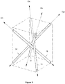
- the figure 5 represents an assembly of tubular elements according to the invention, the tubes being arranged in four distinct directions of a rectangular parallelepiped.
- the tubes of Figures 3 to 5 are represented with a substantially circular section, however, the tubes may have a section of different shape: square, rectangle, polygon, circle, ellipse ... All embodiments of the section of the tube are compatible with the various embodiments described below.
- FIG 3 illustrates a bundle of four tubes 1a to 1d, each disposed in one of four assembly directions Da to Dd.
- the four directions Da to Dd in which the tubes are assembled correspond respectively to the four diagonals of a rectangular parallelepiped, except that the tubes do not intersect at the intersection of the diagonals in the center of the rectangular parallelepiped, but meet in the neighborhood of this point.
- the construction of the ordered assembly can begin for example by repeating the layout of the figure 3 , that is to say by arranging along a construction axis XX 'presented in figure 4 , corresponding to the point of intersection of the four tubes of a beam, a new bundle of tubes 1a to 1d arranged in the same order as the previous beam, and so on.
- an ordered assembly start formed of a first row 100a of tube bundles 1a to 1d aligned along the axis.
- an interweaving of four tube networks 11 to 14 which each extend in a plane oriented along one of the four assembly directions of the tubes in a bundle.
- the tubes of each network are spaced from each other by a distance allowing the passage (crisscrossing) of the tubes of the other networks.
- the packing structure is obtained by adding an additional row of bundles along a new axis parallel to the construction axis XX '.
- the free volume is then similarly completed on either side of the row, typically to the end of the tubes of the row 100a, so as to obtain in this volume a three-dimensional structure formed of tubes arranged respectively according to four directions.
- the tubes are interconnected at the contact portions between tubes.
- the bond may be made by a chemical or mechanical process, for example, using a thermoplastic or thermosetting resin, by gluing, by carbon deposition, by welding, by mechanical hooking or other means.
- the structured packing blocks can be machined to the dimensions and shape of the contacting column.
- the contacting columns comprise a cylindrical enclosure.
- the ordered assembly of tubes is machined to obtain a packing structure which has a cylindrical shape which can be introduced into the cylindrical chamber of the column of in order to occupy a maximum of space in the column and thus to offer an optimal exchange surface.
- the structured packing blocks can be cut or machined in the form of rectangular parallelepiped blocks, the large dimension of which will be arranged when it is arranged in a contacting column, parallel to the axis of the column; ie the vertical axis.
- the arrangement of the blocks can be made in successive slices, without particular orientation of the base of the blocks from one slice to another.
- the figure 5 is an example of a rectangular parallelepiped block that can be machined for this embodiment of the invention.
- the figure 9 illustrates a nonlimiting example of arrangement of rectangular parallelepiped blocks 6 in a column 5.
- the blocks are distributed over two structured packing slices arranged one above the other.
- the section of the tubes has an elliptical shape.
- This elliptical shape of the section of the tubes makes it possible to obtain a solid arrangement of the bundles of tubes of the packing structure according to the invention (bundle of four tubes oriented along the four directions of the diagonals of a rectangular parallelepiped).
- circular section tubes are less suitable for obtaining a solid arrangement in the case of a parallelepiped structure.
- the arrangement of elliptical section tubes ensures good spacing between the tubes and ensure points of contact between the tubes.
- the geometry and dimensions of the ellipse are related to the geometry and dimensions of the rectangular parallelepiped.
- the figure 8 represents an example of an elliptical section of a tube 1 for structured packing according to the invention.
- the figure 6 represents an example of a tube 1 of polygonal section for structured packing according to the invention.
- the illustrated tube 1 is formed by a set of rings 7 of polygonal shape, here hexagonal, connected by rods 8 parallel to the axis of the tube, and corresponding generatrices of the tube. The spaces formed between the rings and the rods correspond to the orifices T of the tubes.
- the figure 7 is a view of the passage section for an elliptical section tube in an arrangement according to an embodiment according to the invention. As illustrated, the arrangement of tubes is formed of tubes of elliptical section 1 according to an embodiment very close to that described for the figure 6 . The central part of the figure 7 corresponds to a space in which a tube 1 can be inserted.
- the internal packing of the contacting column according to the present invention makes it possible to obtain excellent results in distillation operations, in particular for the manufacture of fluorinated derivatives requiring distillations in the presence of HF (hydrofluoric acid) or the distillation of certain organic acids, such as formic acid or acetic acid. It is also particularly well suited for reactive absorption applications, including post-combustion carbon dioxide capture and natural gas processing, by contacting the gas with a liquid absorbing solution.
- the structured packing blocks can be machined in the form of rectangular parallelepiped blocks. Then, the blocks are arranged in a contacting column, so that their lengths (the largest dimension) are parallel to the axis of the column, that is to say the vertical axis.
- the arrangement of the blocks can be achieved in successive slices, without particular orientation of a slice to another.
- the figure 5 is an example of a rectangular parallelepiped block that can be machined for this embodiment of the invention.
- the figure 9 illustrates a nonlimiting example of arrangement of rectangular parallelepiped blocks 6 in a column 5. For this example, the blocks are distributed over two structured packing slices arranged one above the other.
- a comparative example of the packing structure according to the invention with a packing structure according to the prior art with a scheduling of bundles of tubes according to the four directions of a cube allows to show the gains in terms of loss of loads, and therefore an increase in capacity, for the packing structure according to the invention.
- the example consists in putting a liquid, water, or a gas in contact with air, circulating in countercurrent, by means of a structured packing.
- the hydraulic diameter of the tubes is 12 mm
- the opening rate of the tubes is 50%
- the gas flow rate is constant at an absolute pressure of 1.5 bar and at a temperature of ambient
- the diameter of the column is 150 mm.
- the tubes have an elliptical section, and the angle of the tubes with respect to a vertical axis is 30 °.
- the figure 10 represents the linear pressure loss ⁇ P / m expressed in mbar / mm as a function of the kinetic factor Fs expressed in ⁇ Pa for various configurations, one with tubes inclined according to the prior art AA (patent FR 2913897 ) and the other at 30 ° according to the invention INV.
- the kinetic factor characterizes the kinetic energy of the gas in the packing. This value takes into account the effect of the pressure on the packing capacity.
- the liquid flow rate is 100 m 3 / h / m 2 .
- the capacity gain measured for this liquid flow is 50%, and the reduction in linear pressure loss is a factor of 3.
- the figure 11 is a curve identical to the curve of the figure 10 , for an example for which the liquid flow rate is 50 m 3 / h / m 2 . With this liquid flow, the variations are similar to those of the example of the figure 10 : a gain of 50% of the capacity and a reduction in linear pressure loss of a factor close to 3.5.
- the packing structure according to the invention has an increased capacity compared to the packing structure according to the prior art.
Description
La présente invention concerne le domaine des équipements de mise en contact de fluides.The present invention relates to the field of equipment for contacting fluids.
Les colonnes de mise en contact ont pour but de mettre en contact des fluides afin de réaliser des transferts de matière ou de chaleur entre les fluides. Ce type d'équipement de mise en contact de fluides est largement utilisé pour réaliser des opérations de distillation, de rectification, d'absorption, d'échange de chaleur, d'extraction, de réaction chimique, etc.The contacting columns are intended to put in contact fluids in order to achieve transfers of material or heat between the fluids. This type of fluid contacting equipment is widely used to perform distillation, rectification, absorption, heat exchange, extraction, chemical reaction, etc. operations.
Les colonnes de mise en contact sont généralement constituées d'une enceinte munie d'éléments de mise en contact interne favorisant l'échange entre les fluides. En général, la colonne permet de mettre en contact intime une phase gazeuse ascendante avec une phase liquide descendante, ou inversement. Dans la colonne, les fluides peuvent circuler à co-courant ou à contre-courant. Les éléments de mise en contact qui augmentent la surface de contact entre les fluides, peuvent être des plateaux, un garnissage structuré, (c'est-à-dire la juxtaposition de plusieurs éléments unitaires identiques ou non, agencés de manière ordonnée, par exemple des feuillets ondulés) ou un garnissage en vrac (c'est-à-dire des empilements anarchiques d'éléments unitaires, par exemple des anneaux, des spirales).The contacting columns generally consist of an enclosure provided with internal contacting elements promoting the exchange between the fluids. In general, the column makes it possible to intimately contact an ascending gas phase with a descending liquid phase, or conversely. In the column, the fluids can circulate in co-current or against the current. The contacting elements which increase the contact area between the fluids may be trays, a structured packing, (i.e. the juxtaposition of several identical or different unitary elements, arranged in an orderly manner, for example corrugated sheets) or bulk packing (that is, anarchic stacks of unitary elements, e.g. rings, spirals).
Le document
Dans les applications des colonnes de mises en contact de fluides, notamment la distillation ou l'absorption réactive nécessitant le lavage d'un fluide par une solution absorbante, par exemple la désacidification d'un gaz naturel ou la décarbonatation des fumées de combustion, il est primordial de disposer des meilleurs éléments de mise en contact qui présentent une surface de contact maximum, tout en limitant la perte de charge dans la colonne, et qui présentent des coefficients de transfert (liquide et gaz) maximums.In the applications of fluid contacting columns, in particular distillation or reactive absorption requiring the washing of a fluid with an absorbent solution, for example the deacidification of a natural gas or the decarbonation of the combustion fumes, It is essential to have the best contacting elements which have a maximum contact area, while limiting the pressure drop in the column, and which have maximum transfer coefficients (liquid and gas).
Ainsi, le brevet
Ainsi, la présente invention concerne une structure de garnissage formée par un agencement ordonné de faisceau de tubes. Pour chaque faisceau de tubes, les tubes sont orientés selon les quatre directions formées par les diagonales d'un parallélépipède rectangle, qui possède une dimension supérieure aux autres. Ainsi, cet agencement des tubes permet une inclinaison des tubes sur l'axe de la colonne apportant une augmentation de la capacité de la structure de garnissage.Thus, the present invention relates to a packing structure formed by an ordered array of tubes. For each bundle of tubes, the tubes are oriented in the four directions formed by the diagonals of a rectangular parallelepiped, which has a larger dimension than the others. Thus, this arrangement of tubes allows inclination of the tubes on the axis of the column providing an increase in the capacity of the packing structure.
L'invention concerne une structure de garnissage d'une colonne de mise en contact de fluides, ladite structure formant un volume comportant un agencement ordonné de faisceaux de tubes, les parois desdits tubes comportant des orifices disposés de manière à favoriser la circulation et le mélange des fluides dans ladite structure. Chaque faisceau comprend quatre tubes respectivement orientés suivant les quatre directions formées par les diagonales d'un parallélépipède rectangle, ledit parallélépipède rectangle comportant une dimension d'un côté supérieure aux autres.The invention relates to a packing structure of a fluid contacting column, said volume forming structure comprising an ordered arrangement of bundles of tubes, the walls of said tubes having orifices arranged to promote circulation and mixing. fluids in said structure. Each bundle comprises four tubes respectively oriented in the four directions formed by the diagonals of a rectangular parallelepiped, said rectangular parallelepiped having a dimension of one side greater than the others.
Selon l'invention, la plus grande dimension du parallélépipède rectangle est orientée selon la direction verticale de ladite structure du garnissage, selon un axe vertical. Avantageusement, l'angle d'orientation de l'axe desdits tubes par rapport à un axe vertical est compris entre 20 et 50°, de préférence entre 30 et 45°.According to the invention, the largest dimension of the rectangular parallelepiped is oriented in the vertical direction of said structure of the lining, along a vertical axis. Advantageously, the orientation angle of the axis of said tubes relative to a vertical axis is between 20 and 50 °, preferably between 30 and 45 °.
De préférence, le diamètre hydraulique des tubes est compris entre 5 et 50 mm.Preferably, the hydraulic diameter of the tubes is between 5 and 50 mm.
Selon un mode de réalisation de l'invention, lesdits tubes ont sensiblement une section circulaire ou elliptique.According to one embodiment of the invention, said tubes have substantially a circular or elliptical section.
De manière avantageuse, la section desdits tubes est un polygone.Advantageously, the section of said tubes is a polygon.
Conformément à un mode de réalisation de l'invention, ladite structure comporte une pluralité de blocs parallélépipédiques formés par l'agencement ordonné de faisceaux de tubes.According to one embodiment of the invention, said structure comprises a plurality of parallelepiped blocks formed by the ordered arrangement of tube bundles.
Selon une caractéristique, lesdits orifices sont inscrits dans des rectangles dont les côtés mesurent entre 2 et 45 mm et chacun desdits orifices s'étend sur une aire supérieure à 2 mm2.According to one characteristic, said orifices are inscribed in rectangles whose sides measure between 2 and 45 mm and each of said orifices extends over an area greater than 2 mm 2 .
Conformément à une conception de l'invention, le rapport entre l'aire des orifices et l'aire de la partie pleine desdits tubes est compris entre 10 et 90 %, de préférence entre 25 et 50 %.According to a design of the invention, the ratio between the area of the orifices and the area of the solid part of said tubes is between 10 and 90%, preferably between 25 and 50%.
De manière préférée, lesdits tubes comportent un tissage d'au moins deux rubans enroulés suivant au moins deux hélices croisées s'étendant selon un même axe et un même diamètre, lesdits rubans étant distants les uns des autres de manière à former lesdits orifices.Preferably, said tubes comprise a weave of at least two ribbons wound in at least two crossed helices extending along the same axis and the same diameter, said ribbons being spaced from each other so as to form said orifices.
Conformément à un mode de réalisation, lesdits tubes sont formés par une pluralité d'anneaux reliées par au moins une tige, ladite tige étant disposée selon une génératrice dudit tube.According to one embodiment, said tubes are formed by a plurality of rings connected by at least one rod, said rod being disposed along a generatrix of said tube.
Selon une variante, lesdits tubes sont réalisés dans un matériau choisi parmi le carbone figé par dépôt de carbone, un métal, une céramique, un matériau polymère un matériau thermoplastique, un matériau thermodurcissable.According to a variant, said tubes are made of a material chosen from carbon fixed by carbon deposition, a metal, a ceramic, a polymer material a thermoplastic material, a thermosetting material.
De plus, l'invention concerne une colonne de mise en contact de fluides comprenant un garnissage, ledit garnissage comportant une structure de garnissage selon l'une des caractéristiques précédentes.In addition, the invention relates to a fluid contacting column comprising a packing, said packing comprising a packing structure according to one of the preceding features.
En outre, l'invention concerne une utilisation d'une colonne de mise en contact de fluides selon l'invention dans un procédé de distillation, un procédé d'absorption réactive, tel que la capture de gaz acides et le traitement de gaz naturel.In addition, the invention relates to a use of a fluid contacting column according to the invention in a distillation process, a reactive absorption process, such as the capture of acid gases and the treatment of natural gas.
L'invention concerne également un procédé de fabrication d'une structure de garnissage d'une colonne de mise en contact de fluides, dans lequel on réalise les étapes suivantes :
- a) on fabrique des tubes comportant des orifices disposés de manière à favoriser la circulation et le mélange des fluides dans la structure ;
- b) on construit un assemblage ordonné desdits tubes en juxtaposant des faisceaux de tubes, lesdits faisceaux de tubes comprenant quatre tubes respectivement orientés suivant les quatre directions formées par les diagonales d'un parallélépipède rectangle, ledit parallélépipède rectangle comportant une dimension supérieure aux autres ; et
- c) on réalise une liaison des tubes au niveau de leur portion de contact.
- a) tubes are made with orifices arranged so as to promote the circulation and the mixing of the fluids in the structure;
- b) an ordered assembly of said tubes is constructed by juxtaposing bundles of tubes, said bundles of tubes comprising four tubes respectively oriented along the four directions formed by the diagonals of a rectangular parallelepiped, said rectangular parallelepiped having a larger dimension than the others; and
- c) a connection of the tubes is made at their contact portion.
Selon un mode de réalisation, à l'étape a), on fabrique des tubes de section circulaire ou elliptique.According to one embodiment, in step a), tubes of circular or elliptical section are manufactured.
Alternativement, la section desdits tubes est un polygone.Alternatively, the section of said tubes is a polygon.
Selon une variante de réalisation, on oriente la plus grande dimension dudit parallélépipède rectangle selon la direction verticale de ladite structure de garnissage, selon un axe vertical. Conformément à une caractéristique, ledit procédé comprend une étape d'usinage de l'assemblage ordonné pour former des blocs parallélépipédiques rectangles, et une étape d'agencement des blocs dans ladite colonne de mise en contact.According to an alternative embodiment, the largest dimension of said rectangular parallelepiped is oriented in the vertical direction of said packing structure, along a vertical axis. According to one feature, said method comprises a step of machining the ordered assembly to form rectangular parallelepiped blocks, and a step of arranging the blocks in said contacting column.
D'autres caractéristiques et avantages du procédé selon l'invention, apparaîtront à la lecture de la description ci-après d'exemples non limitatifs de réalisations, en se référant aux figures annexées et décrites ci-après.
- La
figure 1 illustre un exemple de tube pour une structure de garnissage selon l'invention. - La
figure 2 illustre un deuxième exemple de tube pour une structure de garnissage selon l'invention. - La
figure 3 représente un faisceau de tubes pour une structure de garnissage selon l'invention. - La
figure 4 représente un agencement de faisceaux de tubes pour une structure de garnissage selon l'invention. - La
figure 5 illustre une structure de garnissage selon un mode de réalisation de l'invention. - La
figure 6 illustre un troisième exemple de tube pour une structure de garnissage selon l'invention. - La
figure 7 est une vue de la section de passage pour un tube elliptique dans un agencement de faisceaux de tubes selon un mode de réalisation de l'invention. - La
figure 8 illustre une section d'un tube elliptique selon une variante de réalisation de l'invention. - La
figure 9 représente une colonne de mise en contact comprenant des blocs de structure de garnissage selon un mode de réalisation de l'invention. - La
figure 10 représente les pertes de charge linéique pour un taux d'arrosage de 100 m3/h/m2 pour une structure de garnissage selon l'art antérieur et pour une structure de garnissage selon l'invention. - La
figure 11 représente les pertes de charge linéique pour un taux d'arrosage de 50 m3/h/m2 pour une structure de garnissage selon l'art antérieur et pour une structure de garnissage selon l'invention.
- The
figure 1 illustrates an exemplary tube for a packing structure according to the invention. - The
figure 2 illustrates a second example of a tube for a packing structure according to the invention. - The
figure 3 represents a bundle of tubes for a packing structure according to the invention. - The
figure 4 represents a tube bundle arrangement for a packing structure according to the invention. - The
figure 5 illustrates a packing structure according to one embodiment of the invention. - The
figure 6 illustrates a third example of a tube for a packing structure according to the invention. - The
figure 7 is a view of the passage section for an elliptical tube in a tube bundle arrangement according to one embodiment of the invention. - The
figure 8 illustrates a section of an elliptical tube according to an alternative embodiment of the invention. - The
figure 9 represents a contacting column comprising packing structure blocks according to one embodiment of the invention. - The
figure 10 represents the linear pressure losses for a watering rate of 100 m 3 / h / m 2 for a packing structure according to the prior art and for a packing structure according to the invention. - The
figure 11 represents the linear pressure losses for a watering rate of 50 m 3 / h / m 2 for a packing structure according to the prior art and for a packing structure according to the invention.
La présente invention concerne une structure de garnissage d'une colonne de mise en contact de fluides. La structure de garnissage selon l'invention forme un volume comportant un agencement ordonné de faisceaux de tubes. On appelle tube, un cylindre creux, possédant une section sensiblement constante, et dont la dimension perpendiculaire à la section (selon la génératrice du cylindre) est la plus grande dimension de l'élément creux. Un tube peut avoir une section quelconque, par exemple carré, rectangulaire, polygonale, circulaire, elliptique...Selon l'invention, les parois des tubes comportent des orifices disposés de manière à favoriser la circulation et le mélange des fluides dans la structure.The present invention relates to a packing structure of a fluid contacting column. The packing structure according to the invention forms a volume comprising an ordered arrangement of bundles of tubes. A tube is a hollow cylinder, having a substantially constant section, and whose dimension perpendicular to the section (depending on the generatrix of the cylinder) is the largest dimension of the hollow element. A tube may have any cross section, for example square, rectangular, polygonal, circular, elliptical ... According to the invention, the walls of the tubes comprise orifices arranged so as to promote the circulation and the mixing of the fluids in the structure.
Selon l'invention, chaque faisceau de tubes comprend quatre tubes orientés suivant les quatre directions des diagonales d'un parallélépipède rectangle (ou pavé).. Ainsi, le parallélépipède rectangle n'est pas un cube et comporte donc une dimension supérieure aux autres dimensions, ce qui permet de réduire les angles d'orientation des tubes par rapport au plan vertical, car ces angles sont différents des angles formés par les directions d'un cube. Ainsi, il est possible d'augmenter la capacité de la structure de garnissage. On rappelle que la capacité d'un garnissage correspond à la quantité de gaz passant dans un garnissage sans être en engorgement, c'est-à-dire sans créer d'accumulation de gaz dans une partie du garnissage. Les directions des tubes correspondent sensiblement aux quatre diagonales d'un parallélépipède rectangle, à ceci près que les tubes ne s'entrecoupent pas au niveau de l'intersection théorique des diagonales au centre du parallélépipède rectangle, mais se croisent au voisinage de ce point.According to the invention, each bundle of tubes comprises four tubes oriented along the four directions of the diagonals of a rectangular parallelepiped (or paved). Thus, the rectangular parallelepiped is not a cube and therefore has a dimension greater than the other dimensions which makes it possible to reduce the angles of orientation of the tubes with respect to the vertical plane, because these angles are different from the angles formed by the directions of a cube. Thus, it is possible to increase the capacity of the packing structure. It is recalled that the capacity of a lining corresponds to the amount of gas passing through a lining without being clogged, that is to say without creating accumulation of gas in a portion of the lining. The directions of the tubes correspond substantially to the four diagonals of a rectangular parallelepiped, except that the tubes do not intersect at the theoretical intersection of the diagonals in the center of the rectangular parallelepiped, but intersect in the vicinity of this point.
La
L'élément 1 est constitué d'une paroi en forme de tube de diamètre hydraulique θ pourvue d'orifices ou trous T. Le diamètre hydraulique d'un tube est une notation communément utilisée pour le calcul des écoulements dans un tube, une conduite hydraulique ou un canal, de manière à faire des calculs similaires à ceux d'un tube de section circulaire, lorsque la section du tube n'est pas circulaire. Le diamètre hydraulique θ peut être défini selon une formule du type : ![]()
![]()
Selon une conception avantageuse de l'invention, on choisit l'aire minimum des orifices T supérieure à 2 mm2, de préférence 4 mm2, de manière à ce que le film liquide qui s'écoule à l'intérieur des tubes puisse être cassé par un flux de gaz qui traverse les orifices. En effet, si la taille des orifices T est inférieure à 2 mm2, le film liquide qui circule sur la paroi interne d'un tube risque de boucher par capillarité ces orifices. Les orifices présentant une surface supérieure à 2 mm2 permettent le passage des phases gazeuses et liquides d'un tube à l'autre, et d'assurer ainsi un bon contact et un bon mélange. Dans l'application du garnissage selon l'invention à l'absorption réactive, on préfère utiliser des tubes munis d'orifices dont l'aire est supérieure à 4 mm2, voire 8 mm2. En effet, en général, les fluides mis en contact dans une colonne d'absorption réactive circulent à grande vitesse, typiquement à des vitesses comprises entre 1 m/s et 2 m/s. De ce fait, on prévoit des orifices plus grands afin de fragmenter le film liquide en circulation à la paroi des tubes.According to an advantageous design of the invention, the minimum area of the orifices T greater than 2 mm 2 , preferably 4 mm 2 , is chosen so that the liquid film flowing inside the tubes can be broken by a flow of gas through the orifices. Indeed, if the size of the orifices T is less than 2 mm 2 , the liquid film which circulates on the inner wall of a tube may clog these holes by capillary action. The orifices having an area greater than 2 mm 2 allow the passage of gaseous and liquid phases from one tube to another, and thus ensure good contact and good mixing. In the application of the packing according to the invention to reactive absorption, it is preferred to use tubes provided with orifices whose area is greater than 4 mm 2 , or even 8 mm 2 . Indeed, in general, the fluids contacted in a reactive absorption column circulate at high speed, typically at speeds between 1 m / s and 2 m / s. As a result, larger orifices are provided in order to fragment the circulating liquid film at the wall of the tubes.
Selon une variante de réalisation de l'invention, les orifices T sont inscrits dans des rectangles de longueur L et de largeur I comprises entre 2 et 45 mm, de préférence entre 3 et 20 mm. Autrement dit, un orifice doit toucher les quatre côtés d'un rectangle de longueur L et de largeur l. Par contre, la forme d'un orifice T peut être quelconque, tant qu'il reste inscrit dans un rectangle de dimensions L et l. L'orifice peut avoir une forme sensiblement circulaire, une forme d'ellipse, une forme de losange... Le fait d'inscrire les orifices dans des rectangles de dimensions L et l permet d'imposer une dimension minimum entre les bords des orifices, afin de provoquer la cassure du film liquide circulant sur la paroi des tubes du garnissage.According to an alternative embodiment of the invention, the orifices T are inscribed in rectangles of length L and width I of between 2 and 45 mm, preferably between 3 and 20 mm. In other words, an orifice must touch the four sides of a rectangle of length L and width l. On the other hand, the shape of an orifice T can be any, as long as it remains inscribed in a rectangle of dimensions L and l. The orifice may have a substantially circular shape, an ellipse shape, a rhomboid shape ... The fact of inscribing the orifices in rectangles of dimensions L and l makes it possible to impose a minimum dimension between the edges of the orifices. , in order to cause the breaking of the liquid film flowing on the wall of the tubes of the lining.
Les orifices T sont disposés de manière ordonnée ou aléatoire. De préférence, les orifices T sont disposés de manière régulière pour obtenir des caractéristiques d'échanges homogènes le long de l'élément 1. De préférence, l'espace entre deux orifices n'excède pas 2 fois la valeur du diamètre hydraulique θ. On peut choisir le nombre d'orifices de manière à ce que l'élément 1 comporte entre 10% et 90% d'ouverture, c'est-à-dire que le rapport entre l'aire des orifices et l'aire de la partie pleine du tube soit compris entre 10% et 90%, une excellente valeur de ce rapport étant comprise entre 25% et 50%.The orifices T are arranged in an orderly or random manner. Preferably, the orifices T are arranged in a regular manner to obtain homogeneous exchange characteristics along the
Les orifices T tels que définis ci-dessus, ouvrent des voies de communication au fluide entre l'intérieur et l'extérieur de l'élément 1 afin d'optimiser le mélange entre les phases, donc le contact et la redistribution entre les phases, circulant dans un garnissage structuré composé de tubes 1.The orifices T as defined above, open channels of communication to the fluid between the inside and the outside of the
Les tubes 1 peuvent être réalisés avec tout type de matériau, par exemple en carbone/carbone, c'est-à-dire une structure en fibres de carbone figée par dépôt de carbone, en céramique, en métal, en matière polymère, en matériau thermoplastique ou en matériau thermodurcissable. Les orifices T peuvent être obtenus par retrait de matière, par exemple par usinage ou perçage. L'élément 1 peut être obtenu par moulage, par exemple d'un matériau polymère, par formage, ou tout autre procédé.The
La
Selon le mode de réalisation illustré, l'élément tubulaire 1 de la
Sur la
Sans sortir du cadre de l'invention, on peut réaliser des éléments tubulaires 1 en faisant varier différents paramètres, par exemple le nombre de rubans, l'épaisseur et la largeur de chacun des rubans, le pas de l'hélice d'enroulement, voire effectuer des enroulements de rubans selon des hélices à pas variable.Without departing from the scope of the invention, it is possible to produce
Une fois l'enroulement de rubans effectué, on fige la structure de rubans tissés, par exemple par une technique décrite dans le document
Pour tous les modes de réalisation de l'invention, les tubes peuvent être réalisés avec tout type de matériau, par exemple en carbone/carbone, c'est-à-dire une structure en fibres de carbone figée par dépôt de carbone, en céramique, en métal, en matière polymère, en matériau thermoplastique ou en matériau thermodurcissable. Les orifices peuvent être obtenus par retrait de matière, par exemple par usinage ou perçage. L'élément 1 peut être obtenu par moulage, par exemple d'un matériau polymère, par formage, ou tout autre procédé.For all the embodiments of the invention, the tubes may be made with any type of material, for example carbon / carbon, that is to say a carbon fiber structure fixed by carbon deposition, ceramic metal, polymer material, thermoplastic material or thermosetting material. The orifices may be obtained by removal of material, for example by machining or drilling. The
Selon l'invention, chaque faisceau de tubes comprend quatre tubes orientés suivant les quatre directions formées par les diagonales d'un parallélépipède rectangle, ce dernier comportant au moins une dimension (d'un côté) supérieure aux autres dimensions (des autres côtés) pour augmenter la capacité de la structure de garnissage. Ainsi, les tubes sont positionnés sensiblement suivant les quatre diagonales d'un parallélépipède rectangle, à ceci près que les tubes ne s'entrecoupent pas au niveau de l'intersection des diagonales au centre du parallélépipède rectangle, mais se croisent au voisinage de ce point. Le parallélépipède rectangle est orienté de telle sorte que sa plus grande dimension (la longueur) soit placée sensiblement suivant l'axe de la colonne dans laquelle il est inséré (direction des écoulements gazeux et/ou liquides), cet axe est généralement vertical. Grâce à cet agencement des tubes et à l'inclinaison résultante des tubes par rapport au plan vertical, la capacité de la structure de garnissage est augmentée.According to the invention, each bundle of tubes comprises four tubes oriented along the four directions formed by the diagonals of a rectangular parallelepiped, the latter comprising at least one dimension (on one side) greater than the other dimensions (on the other sides) for increase the capacity of the packing structure. Thus, the tubes are positioned substantially along the four diagonals of a rectangular parallelepiped, except that the tubes do not intersect at the intersection of the diagonals in the center of the rectangular parallelepiped, but intersect in the vicinity of this point. . The rectangular parallelepiped is oriented so that its largest dimension (the length) is placed substantially along the axis of the column in which it is inserted (direction of the gaseous and / or liquid flows), this axis is generally vertical. Due to this arrangement of the tubes and the resulting inclination of the tubes relative to the vertical plane, the capacity of the packing structure is increased.
Selon un mode de réalisation de l'invention, le parallélépipède rectangle comporte une base carré.According to one embodiment of the invention, the rectangular parallelepiped comprises a square base.
Avantageusement, l'angle formé par l'axe de chaque tube par rapport à un axe vertical, dans un plan vertical passant par l'axe du tube, est compris entre 20 et 55°, avantageusement entre 20 et 50° pour obtenir un effet important pour la capacité de la structure de garnissage. De manière préférée, cet angle est compris entre 30 et 45° pour obtenir des résultats optimaux en termes de capacité de la structure de garnissage.Advantageously, the angle formed by the axis of each tube relative to a vertical axis, in a vertical plane passing through the axis of the tube, is between 20 and 55 °, advantageously between 20 and 50 ° to obtain an effect important for the capacity of the packing structure. Preferably, this angle is between 30 and 45 ° to obtain optimum results in terms of capacity of the packing structure.
La
L'agencement détaillé de cet assemblage est décrit en référence aux
La construction de l'assemblage ordonné peut débuter par exemple en répétant la disposition de la
Lorsqu'on a atteint le nombre désiré de faisceaux dans la rangée 100a, on superpose ensuite plusieurs séries de rangées de faisceaux suivant des axes parallèles à l'axe XX' de manière à remplir le volume libre autour de la rangée 100a. Ensuite, la structure de garnissage est obtenue par ajout d'une rangée supplémentaire de faisceaux selon un nouvel axe parallèle à l'axe de construction XX'. On complète ensuite de la même façon le volume libre de part et d'autre de la rangée, typiquement jusqu'à l'extrémité des tubes de la rangée 100a, de manière à obtenir dans ce volume une structure tridimensionnelle formée de tubes respectivement disposés suivant quatre directions.When the desired number of beams in the
Selon une variante de réalisation de l'invention, et dans les assemblages de tubes décrits en référence aux
Selon un mode de réalisation de l'invention, les blocs de garnissage structuré peuvent être usinés aux dimensions et à la forme de la colonne de mise en contact. En général, les colonnes de mise en contact comportent une enceinte cylindrique. Dans ce cas, on usine l'assemblage ordonné de tubes pour obtenir une structure de garnissage qui présente une forme cylindrique qui peut être introduite dans l'enceinte cylindrique de la colonne de manière à occuper un maximum d'espace dans la colonne et offrir ainsi une surface d'échange optimale.According to one embodiment of the invention, the structured packing blocks can be machined to the dimensions and shape of the contacting column. In general, the contacting columns comprise a cylindrical enclosure. In this case, the ordered assembly of tubes is machined to obtain a packing structure which has a cylindrical shape which can be introduced into the cylindrical chamber of the column of in order to occupy a maximum of space in the column and thus to offer an optimal exchange surface.
Pour les colonnes de grand diamètre, on effectue une juxtaposition de plusieurs blocs. Les blocs situés à la périphérie interne de la paroi sont usinés pour être adaptés à la forme cylindrique de la colonne. L'usinage des blocs formés par l'assemblage des éléments tubulaires est très délicat compte tenu de la forte porosité intrinsèque à la construction. Selon la nature des matériaux, on emploie des techniques particulières d'usinage pour éviter le flambage des éléments ou l'effondrement de la structure, par exemples par usinage laser, jet d'eau ou usinage à grande vitesse d'outils.For large diameter columns, several blocks are juxtaposed. The blocks located at the inner periphery of the wall are machined to be adapted to the cylindrical shape of the column. The machining of the blocks formed by the assembly of the tubular elements is very delicate given the high porosity intrinsic to the construction. Depending on the nature of the materials, particular machining techniques are used to avoid buckling of the elements or collapse of the structure, for example by laser machining, water jet or high-speed machining of tools.
Alternativement, les blocs de garnissage structuré peuvent être découpés ou usinés sous forme de blocs parallélépipédiques rectangles, dont la grande dimension sera disposée lors de son agencement dans une colonne de mise en contact, parallèlement à l'axe de la colonne, c'est-à-dire l'axe vertical. L'agencement des blocs peut être réalisé par tranches successives, sans orientation particulière de la base des blocs d'une tranche à l'autre. La
Selon un mode de réalisation de l'invention, la section des tubes a une forme elliptique. Cette forme elliptique de la section des tubes permet d'obtenir un agencement solide des faisceaux de tubes de la structure de garnissage selon l'invention (faisceau de quatre tubes orientés selon les quatre directions des diagonales d'un parallélépipède rectangle). En effet, les tubes de section circulaire sont moins adaptés pour l'obtention d'un agencement solide dans le cas d'une structure parallélépipédique. De plus, l'agencement de tubes de section elliptique permet d'assurer un bon espacement entre les tubes et d'assurer des points de contact entre les tubes. De manière avantageuse, la géométrie et les dimensions de l'ellipse sont liées à la géométrie et aux dimensions du parallélépipède rectangle.According to one embodiment of the invention, the section of the tubes has an elliptical shape. This elliptical shape of the section of the tubes makes it possible to obtain a solid arrangement of the bundles of tubes of the packing structure according to the invention (bundle of four tubes oriented along the four directions of the diagonals of a rectangular parallelepiped). Indeed, circular section tubes are less suitable for obtaining a solid arrangement in the case of a parallelepiped structure. In addition, the arrangement of elliptical section tubes ensures good spacing between the tubes and ensure points of contact between the tubes. Advantageously, the geometry and dimensions of the ellipse are related to the geometry and dimensions of the rectangular parallelepiped.
De plus, les spécificités géométriques décrites en rapport avec la
La
La
La
Le garnissage interne de colonne de mise en contact selon la présente invention permet d'obtenir d'excellents résultats dans les opérations de distillation, notamment pour la fabrication des dérivés fluorés nécessitant des distillations en présence de HF (acide fluorhydrique) ou la distillation de certains acides organiques, tel l'acide formique ou l'acide acétique. Il est également particulièrement bien adapté aux applications d'absorption réactive, notamment la capture de dioxyde de carbone en post-combustion et le traitement du gaz naturel, par mise en contact du gaz avec une solution liquide absorbante.The internal packing of the contacting column according to the present invention makes it possible to obtain excellent results in distillation operations, in particular for the manufacture of fluorinated derivatives requiring distillations in the presence of HF (hydrofluoric acid) or the distillation of certain organic acids, such as formic acid or acetic acid. It is also particularly well suited for reactive absorption applications, including post-combustion carbon dioxide capture and natural gas processing, by contacting the gas with a liquid absorbing solution.
La présente invention concerne, en outre, un procédé de fabrication d'une structure de garnissage d'une colonne de mise en contact de fluides. Le procédé de fabrication permet de réaliser une structure de garnissage selon l'une quelconque des variantes de réalisation décrites précédemment. Pour le procédé de fabrication selon l'invention, on réalise les étapes suivantes :
- a) on fabrique des tubes comportant des orifices disposés de manière à favoriser la circulation et le mélange des fluides dans la structure. Les tubes peuvent notamment prendre la forme d'un tube tel qu'illustré sur l'une des
figures 1, 2 ou 6 . Le tube peut avoir une section de forme quelconque : carré, rectangle, polygone, cercle, ellipse... Par exemple, une section elliptique telle qu'illustrée sur lafigure 8 . Les tubes peuvent être réalisés avec tout type de matériau, par exemple en carbone/carbone, c'est-à-dire une structure en fibres de carbone figée par dépôt de carbone, en céramique, en métal, en matière polymère, en matériau thermoplastique ou en matériau thermodurcissable.
Pour un tube selon le mode de réalisation de lafigure 1 , sa fabrication peut consister à réaliser dans un premier temps un tube plein, puis à découper des orifices aux endroits souhaités, par exemple par usinage ou par perçage. Le tube peut être obtenu par moulage, par exemple d'un matériau polymère, par formage, ou tout autre procédé.
Pour un tube selon le mode de réalisation de lafigure 2 , sa fabrication peut être mise en oeuvre par tissage de rubans, par exemple des mèches, des fils, des feuillards, épousant une forme tubulaire. Plus précisément, un premier ruban peut être enroulé, en formant une hélice, autour d'un tube et un deuxième ruban peut être également enroulé, en formant une hélice, autour du même tube, en étant croisé par rapport au premier ruban. On choisit l'épaisseur des rubans et le pas des hélices de manière à ce qu'il subsiste des espaces entre les rubans. Le tube peut être réalisé par plusieurs paires de ruban enroulé.
Pour un tube selon le mode de réalisation de lafigure 6 , sa fabrication peut être mise en oeuvre par :- fabrication d'anneaux de forme souhaitée, polygone, cercle, ellipse,
- fabrication de tiges, et
- fixation des tiges sur les anneaux, les tiges correspondant à la génératrice du tube et les anneaux correspondant à la section du tube. Si les anneaux et les tiges sont métalliques, la fixation peut être réalisée par soudage. Si les anneaux et les tiges sont en matériau polymère, leur fixation peut être réalisée par collage ou au cours du procédé de polymérisation de la matière, thermoplastique ou thermodurcissable.
- b) Ensuite, on construit un assemblage ordonné des tubes en juxtaposant des faisceaux de tubes. Selon l'invention, chaque faisceau de tubes comprend quatre tubes respectivement orientés suivant quatre directions d'un parallélépipède rectangle, le parallélépipède rectangle comportant une dimension supérieure aux autres. De préférence, la plus grande dimension du parallélépipède correspond à la direction verticale de la structure de garnissage (cf.
figure 3 ). Les directions d'un parallélépipède rectangle correspondent sensiblement aux quatre diagonales d'un parallélépipède rectangle, à ceci près que les tubes ne s'entrecoupent pas au niveau de l'intersection des diagonales au centre du parallélépipède rectangle, mais se croisent au voisinage de ce point. Grâce à cet agencement des tubes, la capacité de la structure de garnissage est augmentée.
Avantageusement, l'angle formé par l'axe de chaque tube par rapport au plan horizontal, dans un plan vertical passant par l'axe du tube, est compris entre 20 et 54° pour obtenir un effet important pour la capacité de la structure de garnissage. De manière préférée, cet angle est compris entre 30 et 45° pour obtenir des résultats optimaux en termes de capacité de la structure de garnissage.
La construction de l'assemblage ordonné peut débuter par exemple en répétant la disposition de lafigure 3 , c'est à dire en disposant suivant un axe de construction XX', correspondant au point d'entrecroisement des quatre tubes d'un faisceau, un nouveau faisceau de tubes 1a à 1d disposé dans le même ordre que le faisceau précédent, et ainsi de suite. On obtient ainsi, comme représenté sur lafigure 4 , un début d'assemblage ordonné formé d'une première rangée 100a de faisceaux de tubes 1a à 1d alignés suivant l'axe de construction XX'. On forme ainsi un entrecroisement de quatre réseaux detubes 11 à 14 qui s'étendent chacun dans un plan orienté suivant une des quatre directions d'assemblage des tubes dans un faisceau. Les tubes de chaque réseau sont espacés les uns des autres par une distance permettant le passage (entrecroisement) des tubes des autres réseaux.
Lorsqu'on a atteint le nombre désiré de faisceaux dans la rangée 100a, on superpose ensuite plusieurs séries de rangées de faisceaux suivant des axes parallèles à l'axe XX' de manière à remplir le volume libre autour de la rangée 100a. Ensuite, la structure de garnissage est obtenue par ajout d'une rangée supplémentaire de faisceaux selon un nouvel axe parallèle à l'axe de construction XX'. On complète ensuite de la même façon le volume libre de part et d'autre de la rangée, typiquement jusqu'à l'extrémité des tubes de la rangée 100a, de manière à obtenir dans ce volume une structure tridimensionnelle formée de tubes respectivement disposés suivant quatre directions. - c) L'étape suivante consiste à lier les tubes entre eux, de manière à créer un agencement rigide. Selon un mode de réalisation de l'invention, les tubes sont liés entre eux au niveau des portions de contact entre tubes. La liaison peut être réalisée par un procédé chimique ou mécanique, par exemple, à l'aide d'une résine thermoplastique ou thermodurcissable, par collage, par dépôt de carbone, par soudage, par crochetage mécanique ou tout autre moyen.
- a) tubes are made with orifices arranged in such a way as to promote the circulation and the mixing of the fluids in the structure. The tubes may in particular take the form of a tube as illustrated on one of the
Figures 1, 2 or6 . The tube can have a section of any shape: square, rectangle, polygon, circle, ellipse ... For example, an elliptical section as illustrated on thefigure 8 . The tubes can be made with any type of material, for example carbon / carbon, that is to say a carbon fiber structure fixed by carbon deposition, ceramic, metal, polymeric material, thermoplastic material or thermosetting material.
For a tube according to the embodiment of thefigure 1 , its manufacture may consist in initially making a solid tube, then cutting holes in the desired locations, for example by machining or drilling. The tube may be obtained by molding, for example a polymeric material, by forming, or any other method.
For a tube according to the embodiment of thefigure 2 its manufacture can be implemented by weaving ribbons, for example strands, threads, strips, marrying a tubular shape. More precisely, a first ribbon can be wound, forming a helix, around a tube and a second ribbon may also be wound, forming a helix, around the same tube, being crossed with respect to the first ribbon. We choose the thickness of the ribbons and the pitch of the propellers so that there remain spaces between the ribbons. The tube can be made by several pairs of coiled ribbon.
For a tube according to the embodiment of thefigure 6 , its manufacture can be implemented by:- manufacture of rings of desired shape, polygon, circle, ellipse,
- stemming, and
- fixing the rods on the rings, the rods corresponding to the generatrix of the tube and the rings corresponding to the section of the tube. If the rings and rods are metallic, the fixing can be done by welding. If the rings and rods are of polymeric material, their attachment can be achieved by gluing or during the polymerization process of the thermoplastic or thermosetting material.
- b) Next, an ordered assembly of the tubes is constructed by juxtaposing bundles of tubes. According to the invention, each bundle of tubes comprises four tubes respectively oriented in four directions of a rectangular parallelepiped, the rectangular parallelepiped having a larger dimension than the others. Preferably, the largest dimension of the parallelepiped corresponds to the vertical direction of the packing structure (cf.
figure 3 ). The directions of a rectangular parallelepiped substantially correspond to the four diagonals of a rectangular parallelepiped, except that the tubes do not intersect at the intersection of the diagonals in the center of the rectangular parallelepiped, but intersect in the vicinity of point. Thanks to this arrangement of the tubes, the capacity of the packing structure is increased.
Advantageously, the angle formed by the axis of each tube relative to the horizontal plane, in a vertical plane passing through the axis of the tube, is between 20 and 54 ° to obtain a significant effect for the capacity of the structure of the tube. packing. Preferably, this angle is between 30 and 45 ° to obtain optimum results in terms of capacity of the packing structure.
The construction of the ordered assembly can begin for example by repeating the layout of thefigure 3 , ie by placing along a construction axis XX ', corresponding to the point of intersection of the four tubes of a bundle, a new bundle of tubes 1a to 1d arranged in the same order as the preceding bundle, and thus right now. Thus, as shown on thefigure 4 , an ordered assembly start formed of afirst row 100a of tube bundles 1a to 1d aligned along the construction axis XX '. We thus form an interweaving of four networks oftubes 11 to 14 which each extend in a plane oriented along one of the four assembly directions of the tubes in a bundle. The tubes of each network are spaced from each other by a distance allowing the passage (crisscrossing) of the tubes of the other networks.
When the desired number of beams in therow 100a has been reached, then several series of rows of beams are superimposed along axes parallel to the axis XX 'so as to fill the free space around therow 100a. Then, the packing structure is obtained by adding an additional row of bundles along a new axis parallel to the construction axis XX '. The free volume is then similarly completed on either side of the row, typically to the end of the tubes of therow 100a, so as to obtain in this volume a three-dimensional structure formed of tubes arranged respectively according to four directions. - c) The next step is to bind the tubes together so as to create a rigid arrangement. According to one embodiment of the invention, the tubes are interconnected at the level of the contact portions between tubes. The bond can be made by a chemical or mechanical process, for example, using a thermoplastic or thermosetting resin, by gluing, carbon deposition, welding, mechanical picking or any other means.
Ensuite, le procédé de fabrication selon l'invention peut comprendre l'une des étapes d) ou d') décrite ci-dessous ou une étape analogue, qui permet de donner une forme à la structure de garnissage.
- d) Selon un mode de réalisation de l'invention, les blocs de garnissage structuré peuvent être usinés aux dimensions et à la forme de la colonne de mise en contact. En général, les colonnes de mise en contact comportent une enceinte cylindrique. Dans ce cas, on usine l'assemblage ordonné de tubes pour obtenir une structure de garnissage qui présente une forme cylindrique qui peut être introduite dans l'enceinte cylindrique de la colonne de manière à occuper un maximum d'espace dans la colonne et offrir ainsi une surface d'échange optimale.
- d') Alternativement, pour les colonnes de grand diamètre, on effectue une juxtaposition de plusieurs blocs. Les blocs situés à la périphérie interne de la paroi sont usinés pour être adaptés à la forme cylindrique de la colonne. L'usinage des blocs formés par l'assemblage des éléments tubulaires est très délicat compte tenu de la forte porosité intrinsèque à la construction. Selon la nature des matériaux, on emploie des techniques particulières d'usinage pour éviter le flambage des éléments ou l'effondrement de la structure, par exemples par usinage laser, jet d'eau ou usinage à grande vitesse d'outils.
- d) According to one embodiment of the invention, the structured packing blocks can be machined to the size and shape of the contacting column. In general, the contacting columns comprise a cylindrical enclosure. In this case, the ordered assembly of tubes is machined to obtain a packing structure which has a cylindrical shape which can be introduced into the cylindrical chamber of the column so as to occupy a maximum of space in the column and thus to offer an optimal exchange surface.
- d ') Alternatively, for large diameter columns, several blocks are juxtaposed. The blocks located at the inner periphery of the wall are machined to be adapted to the cylindrical shape of the column. The machining of the blocks formed by the assembly of the tubular elements is very delicate given the high porosity intrinsic to the construction. Depending on the nature of the materials, particular techniques are employed machining to avoid buckling of the elements or the collapse of the structure, for example by laser machining, water jet or high-speed machining of tools.
Selon une variante de réalisation de l'invention, les blocs de garnissage structuré peuvent être usinés sous forme de blocs parallélépipédiques rectangles. Puis, les blocs sont agencés dans une colonne de mise en contact, de manière à ce que leurs longueurs (la plus grande dimension) soient parallèles à l'axe de la colonne, c'est-à-dire l'axe vertical. L'agencement des blocs peut être réalisé par tranches successives, sans orientation particulière d'une tranche à l'autre. La
Un exemple comparatif de la structure de garnissage selon l'invention avec une structure de garnissage selon l'art antérieur avec un ordonnancement des faisceaux de tubes selon les quatre directions d'un cube (brevet
L'exemple consiste à mettre en contact dans une colonne un liquide, de l'eau, avec un gaz, de l'air, circulant à contre-courant, au moyen d'un garnissage structuré.The example consists in putting a liquid, water, or a gas in contact with air, circulating in countercurrent, by means of a structured packing.
Pour les deux conceptions comparées du garnissage structuré, le diamètre hydraulique des tubes est de 12 mm, le taux d'ouverture des tubes est de 50 %, le débit de gaz est constant à une pression absolue de 1,5 bars et à une température ambiante, et le diamètre de la colonne est de 150 mm.For the two compared designs of the structured packing, the hydraulic diameter of the tubes is 12 mm, the opening rate of the tubes is 50%, the gas flow rate is constant at an absolute pressure of 1.5 bar and at a temperature of ambient, and the diameter of the column is 150 mm.
De plus, pour la conception selon l'invention, les tubes ont une section elliptique, et l'angle des tubes par rapport à un axe vertical est de 30°.In addition, for the design according to the invention, the tubes have an elliptical section, and the angle of the tubes with respect to a vertical axis is 30 °.
La
La
Ainsi, la structure de garnissage selon l'invention présente une capacité augmentée par rapport à la structure de garnissage selon l'art antérieur.Thus, the packing structure according to the invention has an increased capacity compared to the packing structure according to the prior art.
Claims (19)
- A packing structure for a fluid contacting column, said structure forming a volume comprising an ordered arrangement of bundles of tubes (1), the walls of said tubes comprising orifices (T, E) provided so as to promote circulation and mixing of the fluids in said structure, characterized in that each bundle comprises four tubes (1a, 1b, 1c, 1d) respectively oriented in the four directions formed by the diagonals of a rectangular parallelepiped, said rectangular parallelepiped having one side dimension larger than the others.
- A structure as claimed in claim 1, wherein the larger dimension of the rectangular parallelepiped is oriented along a vertical axis.
- A structure as claimed in any one of the previous claims, wherein the angle of orientation of the axis of said tubes (1) with respect to a vertical axis ranges between 20° and 50°, preferably between 30° and 45°.
- A structure as claimed in any one of the previous claims, wherein hydraulic diameter (θ) of tubes (1) ranges between 5 and 50 mm.
- A structure as claimed in any one of the previous claims, wherein said tubes (1) have a substantially circular or elliptical section.
- A structure as claimed in claim 5, wherein the section of said tubes (1) is a polygon.
- A structure as claimed in any one of the previous claims, wherein said structure comprises a plurality of parallelepipedic blocks (6) made up of the ordered arrangement of tube bundles.
- A structure as claimed in any one of the previous claims, wherein said orifices (T, E) are inscribed in rectangles whose sides range between 2 and 45 mm, and each one of said orifices extends over a surface area greater than 2 mm2.
- A structure as claimed in any one of the previous claims, wherein the ratio of the surface area of orifices (T, E) to the surface area of the solid part of said tubes (1) ranges between 10 % and 90 %, preferably between 25 % and 50 %.
- A structure as claimed in any one of the previous claims, wherein said tubes (1) comprise a cloth of at least two strips (2a, 2b, 3a, 3b) wound as two crossed helices extending along the same axis and with the same diameter, said strips (2a, 2b, 3a, 3b) being distant from one another so as to form said orifices (E).
- A structure as claimed in any one of the previous claims, wherein said tubes (1) consist of a plurality of rings (7) connected by at least one rod (8), said rod (8) being arranged along a generatrix of said tube (1).
- A structure as claimed in any one of the previous claims, wherein said tubes (1) are made of a material selected from among carbon congealed by carbon deposition, metal, ceramic, a polymer material or a thermoplastic material, a thermosetting material.
- A fluid contacting column (5) comprising a packing, characterized in that said packing comprises a packing structure as claimed in any one of the previous claims.
- Use of a fluid contacting column (5) as claimed in claim 13 in a distillation process, a reactive absorption process, such as acid gas capture and natural gas treatment.
- A method of manufacturing a packing structure for a fluid contacting column, wherein the following stages are carried out:a) manufacturing tubes (1) comprising orifices (T, E) arranged so as to promote circulation and mixing of the fluids in the structure,b) constructing an ordered assembly of said tubes (1) by juxtaposing bundles of tubes, said tube bundles comprising four tubes (1a, 1b, 1c, 1d) respectively oriented in the four directions formed by the diagonals of a rectangular parallelepiped, said rectangular parallelepiped having one dimension larger than the others, andc) linking tubes (1) together at the contact portion thereof.
- A method as claimed in claim 15 wherein, in stage a), tubes (1) of circular or elliptical section are manufactured.
- A method as claimed in claim 16, wherein the section of said tubes (1) is a polygon.
- A method as claimed in any one of claims 15 to 17, wherein the larger dimension of said rectangular parallelepiped is oriented is oriented along a vertical axis.
- A method as claimed in any one of claims 15 to 18, wherein said method comprises a stage of machining the ordered assembly so as to form rectangular parallelepiped blocks (6) and a stage of laying out blocks (6) in said contacting column (5).
Applications Claiming Priority (1)
| Application Number | Priority Date | Filing Date | Title |
|---|---|---|---|
| FR1558652A FR3040894A1 (en) | 2015-09-15 | 2015-09-15 | OPTIMIZED TRIM STRUCTURE FOR FLUID CONTACT COLUMN AND METHOD OF MANUFACTURE |
Publications (2)
| Publication Number | Publication Date |
|---|---|
| EP3144060A1 EP3144060A1 (en) | 2017-03-22 |
| EP3144060B1 true EP3144060B1 (en) | 2018-06-13 |
Family
ID=55646660
Family Applications (1)
| Application Number | Title | Priority Date | Filing Date |
|---|---|---|---|
| EP16188390.5A Not-in-force EP3144060B1 (en) | 2015-09-15 | 2016-09-12 | Optimised structured packing for fluid contacting column and method of manufacture |
Country Status (4)
| Country | Link |
|---|---|
| US (1) | US20170072380A1 (en) |
| EP (1) | EP3144060B1 (en) |
| CN (1) | CN106512914A (en) |
| FR (1) | FR3040894A1 (en) |
Families Citing this family (1)
| Publication number | Priority date | Publication date | Assignee | Title |
|---|---|---|---|---|
| JP7317021B2 (en) * | 2018-01-08 | 2023-07-28 | コーク-グリッシュ,リミティド パートナーシップ | Structured packing module and assembly method for use in mass transfer columns |
Family Cites Families (8)
| Publication number | Priority date | Publication date | Assignee | Title |
|---|---|---|---|---|
| DE4009885A1 (en) | 1990-03-28 | 1991-10-02 | Goldau Rudi Gmbh | FLOORING |
| DE4104447A1 (en) | 1991-02-14 | 1992-08-20 | Sigri Gmbh | CORROSION AND HEAT RESISTANT ORDERED PACK FOR FABRIC AND HEAT EXCHANGE PROCESSES |
| US5901575A (en) * | 1997-08-25 | 1999-05-11 | Air Products And Chemicals, Inc. | Stackable structured packing with controlled symmetry |
| DE10005457A1 (en) * | 2000-02-08 | 2001-08-09 | Bayer Ag | Static mixer |
| FR2892644B1 (en) * | 2005-10-28 | 2008-02-08 | Snecma Propulsion Solide Sa | TRAPPING STRUCTURE FOR FLUID EXCHANGE COLUMN |
| CN101190406A (en) * | 2006-11-29 | 2008-06-04 | Snecma固体燃料推进器公司 | Filling structure for fluid exchange column |
| FR2913897B1 (en) * | 2007-03-20 | 2009-11-20 | Inst Francais Du Petrole | FLUID STRUCTURE FOR FLUID CONTACT COLUMN AND METHOD OF MANUFACTURING THE SAME. |
| CN104587945A (en) * | 2015-01-24 | 2015-05-06 | 福州大学 | Regular catalytic packing in catalytic distillation column and preparation method of regular catalytic packing |
-
2015
- 2015-09-15 FR FR1558652A patent/FR3040894A1/en active Pending
-
2016
- 2016-09-12 EP EP16188390.5A patent/EP3144060B1/en not_active Not-in-force
- 2016-09-14 US US15/265,578 patent/US20170072380A1/en not_active Abandoned
- 2016-09-18 CN CN201610826738.2A patent/CN106512914A/en active Pending
Non-Patent Citations (1)
| Title |
|---|
| None * |
Also Published As
| Publication number | Publication date |
|---|---|
| FR3040894A1 (en) | 2017-03-17 |
| US20170072380A1 (en) | 2017-03-16 |
| CN106512914A (en) | 2017-03-22 |
| EP3144060A1 (en) | 2017-03-22 |
Similar Documents
| Publication | Publication Date | Title |
|---|---|---|
| EP2129459B1 (en) | Packing structure for a fluid contacting column and production method thereof | |
| EP2134463B2 (en) | High-performance structured packing for a fluid contacting column and method of manufacture | |
| CH697571B1 (en) | packing structure for fluid exchange column. | |
| EP3144060B1 (en) | Optimised structured packing for fluid contacting column and method of manufacture | |
| CA2881773C (en) | High-performance structured packing for a fluid contacting column | |
| FR2918399A1 (en) | Formwork for forming high thickness concrete shear wall of building, has side walls defining space that is provided with filtering elements, where elements define inner volume separated from space by filtering wall permeable to water | |
| WO2019122651A1 (en) | Spacer element with surface texturing, and associated heat exchanger and production method | |
| EP3132222B1 (en) | Heat-exchanger module, use with liquid metal and gas | |
| EP0058628B1 (en) | Heat exchanger with capillary structure for refrigerating machines and/or heat pumps | |
| FR2519066A2 (en) | WELL FILTER OR STRAINER, FORMED BY WINDING FILAMENTS, METHOD AND APPARATUS FOR MANUFACTURING SAME | |
| EP0117829A1 (en) | Tubular heat exchanger | |
| EP2126927B1 (en) | Spacer grille with saddle-shaped support elements and corresponding nuclear fuel assembly | |
| WO2018104124A1 (en) | Method for producing a structured packing using an additive manufacturing method | |
| BE660070A (en) | ||
| FR3113610A1 (en) | WIRED PACKING FOR A MATERIAL EXCHANGE DEVICE | |
| RU2477433C1 (en) | Cooling tower sprayer | |
| FR3075337A1 (en) | INTERCALAR ELEMENT WITH SURFACE TEXTURING, HEAT EXCHANGER COMPRISING SUCH A ELEMENT | |
| FR3075335B1 (en) | HEAT EXCHANGER WITH SUPERIOR INTERCONNECTED ELEMENTS | |
| FR2889582A1 (en) | TUBULAR HEAT EXCHANGER | |
| FR2641066A1 (en) | Improvement to fluid condenser tubes with longitudinal fins and condensers using such tubes | |
| RU2607448C1 (en) | Cooling tower sprinkler | |
| EP1455206A1 (en) | Method of fabricating a photo-crystalline plastic fibre | |
| EP4265358A1 (en) | Method for producing a porous part by laser powder bed fusion | |
| BE567946A (en) | ||
| FR3075341A1 (en) | HEAT EXCHANGER WITH INTERCALAR ELEMENTS WITH SURFACE TEXTURING |
Legal Events
| Date | Code | Title | Description |
|---|---|---|---|
| PUAI | Public reference made under article 153(3) epc to a published international application that has entered the european phase |
Free format text: ORIGINAL CODE: 0009012 |
|
| AK | Designated contracting states |
Kind code of ref document: A1 Designated state(s): AL AT BE BG CH CY CZ DE DK EE ES FI FR GB GR HR HU IE IS IT LI LT LU LV MC MK MT NL NO PL PT RO RS SE SI SK SM TR |
|
| AX | Request for extension of the european patent |
Extension state: BA ME |
|
| 17P | Request for examination filed |
Effective date: 20170922 |
|
| RAP1 | Party data changed (applicant data changed or rights of an application transferred) |
Owner name: IFP ENERGIES NOUVELLES Owner name: HERAKLES |
|
| RBV | Designated contracting states (corrected) |
Designated state(s): AL AT BE BG CH CY CZ DE DK EE ES FI FR GB GR HR HU IE IS IT LI LT LU LV MC MK MT NL NO PL PT RO RS SE SI SK SM TR |
|
| RIC1 | Information provided on ipc code assigned before grant |
Ipc: B01D 3/26 20060101ALI20171011BHEP Ipc: B01J 19/02 20060101ALN20171011BHEP Ipc: B01D 53/18 20060101ALN20171011BHEP Ipc: B01J 19/32 20060101AFI20171011BHEP |
|
| GRAP | Despatch of communication of intention to grant a patent |
Free format text: ORIGINAL CODE: EPIDOSNIGR1 |
|
| INTG | Intention to grant announced |
Effective date: 20180102 |
|
| RAP1 | Party data changed (applicant data changed or rights of an application transferred) |
Owner name: LACOMBE, ALAIN Owner name: IFP ENERGIES NOUVELLES |
|
| GRAS | Grant fee paid |
Free format text: ORIGINAL CODE: EPIDOSNIGR3 |
|
| GRAA | (expected) grant |
Free format text: ORIGINAL CODE: 0009210 |
|
| AK | Designated contracting states |
Kind code of ref document: B1 Designated state(s): AL AT BE BG CH CY CZ DE DK EE ES FI FR GB GR HR HU IE IS IT LI LT LU LV MC MK MT NL NO PL PT RO RS SE SI SK SM TR |
|
| REG | Reference to a national code |
Ref country code: GB Ref legal event code: FG4D Free format text: NOT ENGLISH |
|
| REG | Reference to a national code |
Ref country code: CH Ref legal event code: EP Ref country code: AT Ref legal event code: REF Ref document number: 1007901 Country of ref document: AT Kind code of ref document: T Effective date: 20180615 |
|
| REG | Reference to a national code |
Ref country code: IE Ref legal event code: FG4D Free format text: LANGUAGE OF EP DOCUMENT: FRENCH |
|
| REG | Reference to a national code |
Ref country code: DE Ref legal event code: R096 Ref document number: 602016003541 Country of ref document: DE |
|
| REG | Reference to a national code |
Ref country code: FR Ref legal event code: PLFP Year of fee payment: 3 |
|
| REG | Reference to a national code |
Ref country code: NL Ref legal event code: MP Effective date: 20180613 |
|
| REG | Reference to a national code |
Ref country code: LT Ref legal event code: MG4D |
|
| REG | Reference to a national code |
Ref country code: NO Ref legal event code: T2 Effective date: 20180613 |
|
| PG25 | Lapsed in a contracting state [announced via postgrant information from national office to epo] |
Ref country code: FI Free format text: LAPSE BECAUSE OF FAILURE TO SUBMIT A TRANSLATION OF THE DESCRIPTION OR TO PAY THE FEE WITHIN THE PRESCRIBED TIME-LIMIT Effective date: 20180613 Ref country code: CY Free format text: LAPSE BECAUSE OF FAILURE TO SUBMIT A TRANSLATION OF THE DESCRIPTION OR TO PAY THE FEE WITHIN THE PRESCRIBED TIME-LIMIT Effective date: 20180613 Ref country code: LT Free format text: LAPSE BECAUSE OF FAILURE TO SUBMIT A TRANSLATION OF THE DESCRIPTION OR TO PAY THE FEE WITHIN THE PRESCRIBED TIME-LIMIT Effective date: 20180613 Ref country code: ES Free format text: LAPSE BECAUSE OF FAILURE TO SUBMIT A TRANSLATION OF THE DESCRIPTION OR TO PAY THE FEE WITHIN THE PRESCRIBED TIME-LIMIT Effective date: 20180613 Ref country code: SE Free format text: LAPSE BECAUSE OF FAILURE TO SUBMIT A TRANSLATION OF THE DESCRIPTION OR TO PAY THE FEE WITHIN THE PRESCRIBED TIME-LIMIT Effective date: 20180613 Ref country code: BG Free format text: LAPSE BECAUSE OF FAILURE TO SUBMIT A TRANSLATION OF THE DESCRIPTION OR TO PAY THE FEE WITHIN THE PRESCRIBED TIME-LIMIT Effective date: 20180913 |
|
| PG25 | Lapsed in a contracting state [announced via postgrant information from national office to epo] |
Ref country code: LV Free format text: LAPSE BECAUSE OF FAILURE TO SUBMIT A TRANSLATION OF THE DESCRIPTION OR TO PAY THE FEE WITHIN THE PRESCRIBED TIME-LIMIT Effective date: 20180613 Ref country code: RS Free format text: LAPSE BECAUSE OF FAILURE TO SUBMIT A TRANSLATION OF THE DESCRIPTION OR TO PAY THE FEE WITHIN THE PRESCRIBED TIME-LIMIT Effective date: 20180613 Ref country code: GR Free format text: LAPSE BECAUSE OF FAILURE TO SUBMIT A TRANSLATION OF THE DESCRIPTION OR TO PAY THE FEE WITHIN THE PRESCRIBED TIME-LIMIT Effective date: 20180914 Ref country code: HR Free format text: LAPSE BECAUSE OF FAILURE TO SUBMIT A TRANSLATION OF THE DESCRIPTION OR TO PAY THE FEE WITHIN THE PRESCRIBED TIME-LIMIT Effective date: 20180613 |
|
| REG | Reference to a national code |
Ref country code: AT Ref legal event code: MK05 Ref document number: 1007901 Country of ref document: AT Kind code of ref document: T Effective date: 20180613 |
|
| PG25 | Lapsed in a contracting state [announced via postgrant information from national office to epo] |
Ref country code: NL Free format text: LAPSE BECAUSE OF FAILURE TO SUBMIT A TRANSLATION OF THE DESCRIPTION OR TO PAY THE FEE WITHIN THE PRESCRIBED TIME-LIMIT Effective date: 20180613 |
|
| PG25 | Lapsed in a contracting state [announced via postgrant information from national office to epo] |
Ref country code: IS Free format text: LAPSE BECAUSE OF FAILURE TO SUBMIT A TRANSLATION OF THE DESCRIPTION OR TO PAY THE FEE WITHIN THE PRESCRIBED TIME-LIMIT Effective date: 20181013 Ref country code: EE Free format text: LAPSE BECAUSE OF FAILURE TO SUBMIT A TRANSLATION OF THE DESCRIPTION OR TO PAY THE FEE WITHIN THE PRESCRIBED TIME-LIMIT Effective date: 20180613 Ref country code: AT Free format text: LAPSE BECAUSE OF FAILURE TO SUBMIT A TRANSLATION OF THE DESCRIPTION OR TO PAY THE FEE WITHIN THE PRESCRIBED TIME-LIMIT Effective date: 20180613 Ref country code: PL Free format text: LAPSE BECAUSE OF FAILURE TO SUBMIT A TRANSLATION OF THE DESCRIPTION OR TO PAY THE FEE WITHIN THE PRESCRIBED TIME-LIMIT Effective date: 20180613 Ref country code: SK Free format text: LAPSE BECAUSE OF FAILURE TO SUBMIT A TRANSLATION OF THE DESCRIPTION OR TO PAY THE FEE WITHIN THE PRESCRIBED TIME-LIMIT Effective date: 20180613 Ref country code: CZ Free format text: LAPSE BECAUSE OF FAILURE TO SUBMIT A TRANSLATION OF THE DESCRIPTION OR TO PAY THE FEE WITHIN THE PRESCRIBED TIME-LIMIT Effective date: 20180613 Ref country code: RO Free format text: LAPSE BECAUSE OF FAILURE TO SUBMIT A TRANSLATION OF THE DESCRIPTION OR TO PAY THE FEE WITHIN THE PRESCRIBED TIME-LIMIT Effective date: 20180613 |
|
| PGFP | Annual fee paid to national office [announced via postgrant information from national office to epo] |
Ref country code: PL Payment date: 20180810 Year of fee payment: 3 |
|
| PG25 | Lapsed in a contracting state [announced via postgrant information from national office to epo] |
Ref country code: IT Free format text: LAPSE BECAUSE OF FAILURE TO SUBMIT A TRANSLATION OF THE DESCRIPTION OR TO PAY THE FEE WITHIN THE PRESCRIBED TIME-LIMIT Effective date: 20180613 Ref country code: SM Free format text: LAPSE BECAUSE OF FAILURE TO SUBMIT A TRANSLATION OF THE DESCRIPTION OR TO PAY THE FEE WITHIN THE PRESCRIBED TIME-LIMIT Effective date: 20180613 |
|
| REG | Reference to a national code |
Ref country code: DE Ref legal event code: R097 Ref document number: 602016003541 Country of ref document: DE |
|
| PLBE | No opposition filed within time limit |
Free format text: ORIGINAL CODE: 0009261 |
|
| STAA | Information on the status of an ep patent application or granted ep patent |
Free format text: STATUS: NO OPPOSITION FILED WITHIN TIME LIMIT |
|
| PG25 | Lapsed in a contracting state [announced via postgrant information from national office to epo] |
Ref country code: MC Free format text: LAPSE BECAUSE OF FAILURE TO SUBMIT A TRANSLATION OF THE DESCRIPTION OR TO PAY THE FEE WITHIN THE PRESCRIBED TIME-LIMIT Effective date: 20180613 |
|
| 26N | No opposition filed |
Effective date: 20190314 |
|
| PG25 | Lapsed in a contracting state [announced via postgrant information from national office to epo] |
Ref country code: DK Free format text: LAPSE BECAUSE OF FAILURE TO SUBMIT A TRANSLATION OF THE DESCRIPTION OR TO PAY THE FEE WITHIN THE PRESCRIBED TIME-LIMIT Effective date: 20180613 Ref country code: SI Free format text: LAPSE BECAUSE OF FAILURE TO SUBMIT A TRANSLATION OF THE DESCRIPTION OR TO PAY THE FEE WITHIN THE PRESCRIBED TIME-LIMIT Effective date: 20180613 |
|
| REG | Reference to a national code |
Ref country code: BE Ref legal event code: MM Effective date: 20180930 |
|
| REG | Reference to a national code |
Ref country code: IE Ref legal event code: MM4A |
|
| PG25 | Lapsed in a contracting state [announced via postgrant information from national office to epo] |
Ref country code: LU Free format text: LAPSE BECAUSE OF NON-PAYMENT OF DUE FEES Effective date: 20180912 |
|
| PG25 | Lapsed in a contracting state [announced via postgrant information from national office to epo] |
Ref country code: IE Free format text: LAPSE BECAUSE OF NON-PAYMENT OF DUE FEES Effective date: 20180912 |
|
| PG25 | Lapsed in a contracting state [announced via postgrant information from national office to epo] |
Ref country code: BE Free format text: LAPSE BECAUSE OF NON-PAYMENT OF DUE FEES Effective date: 20180930 |
|
| PGFP | Annual fee paid to national office [announced via postgrant information from national office to epo] |
Ref country code: FR Payment date: 20190925 Year of fee payment: 4 |
|
| PG25 | Lapsed in a contracting state [announced via postgrant information from national office to epo] |
Ref country code: AL Free format text: LAPSE BECAUSE OF FAILURE TO SUBMIT A TRANSLATION OF THE DESCRIPTION OR TO PAY THE FEE WITHIN THE PRESCRIBED TIME-LIMIT Effective date: 20180613 |
|
| PG25 | Lapsed in a contracting state [announced via postgrant information from national office to epo] |
Ref country code: MT Free format text: LAPSE BECAUSE OF FAILURE TO SUBMIT A TRANSLATION OF THE DESCRIPTION OR TO PAY THE FEE WITHIN THE PRESCRIBED TIME-LIMIT Effective date: 20180613 |
|
| PGFP | Annual fee paid to national office [announced via postgrant information from national office to epo] |
Ref country code: DE Payment date: 20191129 Year of fee payment: 4 Ref country code: CH Payment date: 20190925 Year of fee payment: 4 |
|
| PG25 | Lapsed in a contracting state [announced via postgrant information from national office to epo] |
Ref country code: TR Free format text: LAPSE BECAUSE OF FAILURE TO SUBMIT A TRANSLATION OF THE DESCRIPTION OR TO PAY THE FEE WITHIN THE PRESCRIBED TIME-LIMIT Effective date: 20180613 |
|
| REG | Reference to a national code |
Ref country code: NO Ref legal event code: MMEP |
|
| PG25 | Lapsed in a contracting state [announced via postgrant information from national office to epo] |
Ref country code: PT Free format text: LAPSE BECAUSE OF FAILURE TO SUBMIT A TRANSLATION OF THE DESCRIPTION OR TO PAY THE FEE WITHIN THE PRESCRIBED TIME-LIMIT Effective date: 20180613 |
|
| PG25 | Lapsed in a contracting state [announced via postgrant information from national office to epo] |
Ref country code: MK Free format text: LAPSE BECAUSE OF NON-PAYMENT OF DUE FEES Effective date: 20180613 Ref country code: HU Free format text: LAPSE BECAUSE OF FAILURE TO SUBMIT A TRANSLATION OF THE DESCRIPTION OR TO PAY THE FEE WITHIN THE PRESCRIBED TIME-LIMIT; INVALID AB INITIO Effective date: 20160912 |
|
| PG25 | Lapsed in a contracting state [announced via postgrant information from national office to epo] |
Ref country code: NO Free format text: LAPSE BECAUSE OF NON-PAYMENT OF DUE FEES Effective date: 20190930 |
|
| REG | Reference to a national code |
Ref country code: DE Ref legal event code: R119 Ref document number: 602016003541 Country of ref document: DE |
|
| REG | Reference to a national code |
Ref country code: CH Ref legal event code: PL |
|
| GBPC | Gb: european patent ceased through non-payment of renewal fee |
Effective date: 20200912 |
|
| PG25 | Lapsed in a contracting state [announced via postgrant information from national office to epo] |
Ref country code: FR Free format text: LAPSE BECAUSE OF NON-PAYMENT OF DUE FEES Effective date: 20200930 Ref country code: DE Free format text: LAPSE BECAUSE OF NON-PAYMENT OF DUE FEES Effective date: 20210401 |
|
| PG25 | Lapsed in a contracting state [announced via postgrant information from national office to epo] |
Ref country code: LI Free format text: LAPSE BECAUSE OF NON-PAYMENT OF DUE FEES Effective date: 20200930 Ref country code: GB Free format text: LAPSE BECAUSE OF NON-PAYMENT OF DUE FEES Effective date: 20200912 Ref country code: CH Free format text: LAPSE BECAUSE OF NON-PAYMENT OF DUE FEES Effective date: 20200930 |